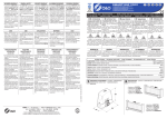
Download chapter 1 - Foster web spares
Transcript
MANUALE DI INSTALLAZIONE USO E MANUTENZIONE VETRINA REFRIGERATA INSTALLATION, OPERATING AND INSTALLATIONS-, BEDIENUNGS- UND MAINTENANCE INSTRUCTIONS WARTUNGSANWEISUNGEN FOR REFRIGERATING DISPLAY CASES KÜHLVITRINE MANUEL D’INSTALLATION D’UTILISATION ET D’ENTRETIEN VETRINES REFRIGEREES ENGLISH INDEX CHAPTER 1 REGULATIONS AND GENERAL WARNINGS 1.1 FINAL TEST AND WARRANTY 1.2 GENERAL SAFETY RULES 1.3 RULES FOR CORRECT OPERATION CHAPTER 2 TECHNICAL DATA 2.1 MACHINE DESCRIPTION 2.2 GAURDS AND SAFETY DEVICES CHAPTER 3 OPERATING INSTRUCTIONS 3.1 DESCRIPTION OF THE OPERATING CONTROLS 3.2 INSTRUCTIONS FOR SETTING UP AND ADJUSTING 3.3 TROUBLE SHOOTING CHAPTER 4 MAINTENANCE 4.1 INSTRUCTIONS FOR ROUTINE MAINTENANCE 4.2 INSTRUCTIONS FOR SPECIAL MAINTENANCE CHAPTER 5 TRANSPORT AND HANDLING CHAPTER 6 STARTING 6.1 6.2 6.3 UNPACKING INSTRUCTIONS ELECTRICAL CONNECTION ASSEMBLING THE PANES OF GLASS The information given in this document is subject to modifications without prior notice. 2 CHAPTER 1 Always use tools which are compatible with and suitable for the parts to be handled. REGULATIONS AND GENERAL WARNINGS Avoid letting any tool come into contact with any part in movement (fans). 1.1 FINAL TEST AND WARRANTY 1.3 RULES FOR CORRECT OPERATION FINAL TEST The product leaves the factory in such a condition as to be set to work by the user. This condition is guaranteed by the tests that the appliance has to pass (electrical test - cooling test - aesthetic inspection) and by the relative certifications endorsing the fact that the appliance is in conformity with the enclosed specifications. The list of rules given below are provided for both the installer and the user, as they concern optimisation of appliance operation. Avoid obstructing the area above, in front of and behind the condenser unit in order to help dispersion of heat from the condenser as much as possible. WARRANTY The appliance and the components we produce are guaranteed for 1 year from the date of consignment and any part or parts thereof, which are shown to the Company’s satisfaction to be defective, will be replaced free of charge. Any such faults shall not, however, be considered if due to incorrect use of the product resulting from the instructions given in this handbook not having been followed. Charges for labour, travel and carriage are not covered by the warranty. Material replaced under guarantee is, however, our property and must therefore be returned at the expense of the customer. 1.2 Always keep the front of the condenser clean by using a soft brush and avoiding the use of rigid or metal utensils which could damage the condenser fins. Check that the surface on which the appliance is to be placed is flat and level. Avoid introducing liquid or solid substances at temperatures above room temperature and in any case do not introduce materials before the appliance has reached operating temperature. GENERAL SAFETY RULES The list of general rules given below is for skilled technical personnel with a good working knowledge of electrical and refrigerating installations. The appliance must be connected to the mains through an omnipolar switch with a contact separation of at least 3 mm (required for appliances supplied without a plug, to be connected to a permanent installation). Check that the voltage and the frequency of the mains supply corresponds to the data on the rating plate. Disconnect the appliance from the mains power supply before carrying out any maintenance operation whatsoever. Do not touch electrical parts with wet hands. 3 ENGLISH CHAPTER 2 ATTENTION !!!! TECHNICAL DATA 2.1 UNDER NO CIRCUMSTANCES MUST THE SAFETY DEVICES BE TAMPERED WITH OR REMOVED. MACHINE DESCRIPTION The appliance consists in a horizontal refrigerating show case for storing foodstuffs for Pizzerias and is divided into 3 basic areas: FAILURE TO OBSERVE THIS RULE RELIEVES THE MANUFACTURER OF ANY RESPONSIBILITY. condensation area this is situated in the right-hand side and is characterised by the presence of the motorcondensing unit. cooling area this is situated inside the foamed insulation and consists in a copper tube applied to the internal compartment. CHAPTER 3 OPERATING INSTRUCTIONS storage area consists in trays inside the internal compartment where foodstuffs can be stored. 3.1DESCRIPTION OF THE OPERATING CONTROLS The cover of the motor-condensing unit is equipped with the switch-on and temperature controls. 2.2 All the manual controls are grouped together on the relative control panel bearing easy-to-read symbols which facilitate immediate operation. These controls are shown schematically in the drawing below: GAURDS AND SAFETY DEVICES All the refrigerator display cabinets are designed and manufactured according to criteria and methods aimed at protecting and safeguarding the user. 1 Risks from moving parts To avoid accidental contact of the operator’s fingers with the blades of the condenser fan, the appliance is fitted with a special guard with airing slits. For safety reasons, to gain access to the motor-condensing compartment the cover must be removed by loosening the fixing screws with a special tool. 4 3 5 Risks due to electricity The electrical system has been designed to standard CEI EN 60204-1. To avoid accidental contact with live parts, all electrical pieces of equipment have been protected by metal guards which can only be removed by using specific tools. Special stickers highlighting the presence of mains voltage are applied near areas (protected in any case) where there is a hazard of an electrical nature. 2 1 - On/off swtich. When the appliance is switched on the green button lights up. 2 - Defrosting light. 3 - Compressor operation light. 4 during which it may be changed using the two 2 and 3 buttons to increase or decrease it respectively. Press the button “set” to confirm the new value. 4 - Digital telethermostat. 5 - Programming key (not accessible to the user). The refrigerating compartment temperature may be set by the user anywhere between the maximum (10° C) and minimum (0° C) levels. 2 - 3 Temperature modification keys. 5 - Selection key. 3.2 INSTRUCTIONS FOR SETTING UP AND ADJUSTING a - Setting the temperature The temperature set during the final test in the factory can be seen by pressing the “set” button. This temperature is displayed for few seconds, 3.3 b - Defrosting The internal compartment must be defrosted periodically by following the sequence hereunder: - disconnect the appliance from the mains. - wait until the traces of ice inside the refrigerating compartment have melted - dry the refrigerating compartment with a soft cloth. - switch the on/off switch to “on”. TROUBLE SHOOTING The causes of malfunctioning are often due to problems that can be easily resolved.Check the following points, according to the problem encountered, and carry out the corresponding recommended operation, before calling the service centre: 1- The refrigerating unit does not start - switching off using the on/off switch - no power supply - other causes 2- the appliance starts again after 3’ check plug, sockets, fuses and power contact the service centre The refrigerating unit operates continuously but does not cool sufficiently ventilate the room or move any heat sources away from the refrigerating unit clean the condenser contact the service centre contact the service centre - room too hot - the condenser is dirty - insufficient quantity of refrig. gas - condenser fan stopped 3- The refrigerating unit does not stop - broken sensor - broken telethermostat 4- Noisy appliance - Persistent vibrations 5- contact the service centre contact the service centre check that the appliance does not touch other objects, either inside or outside. Telethermostat failure signal -e1 = temperature sensor defective contact the service centre If it is impossible to resolve the malfunctioning or trouble using the above check list, only then contact the 5 ENGLISH service centre specifying: Check that the telethermostat and the sensors are in proper working order. - the nature of the fault - the serial number, We recommend you use original spare parts. which can be found on the rating place attached to the rear of the appliance. Failure to observe this rule relieves the manufacturer of any responsibility concerning the correct operation of the appliance. CHAPTER 4 MAINTENANCE CHAPTER 5 4.1 TRANSPORT AND HANDLING INSTRUCTIONS FOR ROUTINE MAINTENANCE A fork lift truck or a transpallet should be used to lift and move the packed product, paying particular attention that the weight is evenly balanced to prevent the risk of tipping. The instructions given in the following paragraph are for the user and consequently for UNSKILLED PERSONNEL. CLEANING THE EQUIPMENT Before starting the appliance and during periodic maintenance work, wash the interior of the refrigerating compartment and the accessories with lukewarm water and a neutral detergent, avoiding the use of abrasive substances or chlorine compounds on the walls. Also avoid using tools which may scratch the metal parts. Rinse thoroughly with clean water and dry carefully. Soften any encrustation with soap and water and delicately remove using a plastic spatula. The packaging consists of cardboard and a wooden pallet. The packing is secured to the pallet by clinching it from the inside. A set of symbols are printed on the cardboard packaging, according to international regulations, giving indications which should be observed during loading and unloading operations, handling and storage of the appliances. These symbols are shown hereunder: TOP PERIODS OF INACTIVITY If the appliance is to be left inactive for long periods, proceed as follows: - unplug the appliance after having turned the on/ off switch to the OFF position -empty the refrigerating compartment and clean thoroughly (see cleaning). 4.2 FRAGILE Handle with care INSTRUCTIONS FOR SPECIAL MAINTENANCE DO NOT EXPOSE TO HUMIDITY The instructions given in the following paragraph are for SKILLED PERSONNEL. PERIODIC OPERATIONS STACKABLE LIMIT Periodically clean the condenser using suitable tools (vacuum cleaner or soft brushes). During both transport/handling and storage a maximum of 2 appliances may be stacked. Check that the electrical connections are not loose. 6 CHAPTER 6 6.2 STARTING Before connecting the appliance to the mains, check that the voltage and the frequency of the latter correspond to the data shown on the rating plate attached to the rear of the appliance. 6.1 UNPACKING INSTRUCTIONS ELECTRICAL CONNECTION The appliance should be unpacked immediately to check that it is intact and has suffered no damage during transport. Any damage should be immediately reported to the carrier. A tolerance of +/- 10% of the rated voltage is allowed. Do not cut the cardboard with sharp tools to avoid damaging the underlying steel panels. The connection is made through a differential switch with a suitable capacity in order to protect the appliance from overloads or short circuits. ATTENTION: do not use plugs or outlets which are not properly earthed! Once the packing has been opened, remove the appliance taking special care with the pack of glass panes located at the bottom of the package. 6.3 ASSEMBLING THE PANES OF GLASS Assemble the feet or, alternatively, the fixing brackets of the marble base. Carry out the operations described hereunder by following the enclosed diagram: Level the appliance by tightening or unscrewing the bottom part of the feet. 1 - Fix the side panes 1 and 2 to the steel structure by means of screws 5. 2 - Fix the back pane 3 to the side panes 1 and 2 by means brackets 6. 3 - Place the cover pane 4 onto the assembled structure and secure it. Remove the PVC protective film from the interior and exterior walls, avoiding the use of metal tools. 4 6 4 1 1 3 3 2 5 7 ITALIANO INDICE CAP. 1 NORME ED AVVERTENZE GENERALI 1.1 1.2 1.3 COLLAUDO E GARANZIA NORME DI SICUREZZA GENERALE NORME DI CORRETTA FUNZIONALITA‘ CAP. 2 DATI TECNICI 2.1 2.2 DESCRIZIONE DELLA MACCHINA PROTEZIONI E DISPOSITIVI DI SICUREZZA CAP. 3 INDICAZIONI RELATIVE ALL‘ USO 3.1 3.2 3.3 DESCRIZIONE DEI COMANDI ATTUATORI ISTRUZIONI PER LA MESSA A PUNTO E REGOLAZIONE ISTRUZIONI PER L‘ IDENTIFICAZIONE E LA LOCALIZZAZIONE DELLE CAUSE DI MANCATO FUNZIONAMENTO CAP. 4 MANUTENZIONE 4.1 4.2 ISTRUZIONI PER LA MANUTENZIONE ORDINARIA ISTRUZIONI PER LA MANUTENZIONE STRAORDINARIA CAP. 5 TRASPORTO E MOVIMENTAZIONE CAP. 6 MESSA IN SERVIZIO 6.1 6.2 6.3 ISTRUZIONI DI SBALLAGGIO COLLEGAMENTO ELETTRICO MONTAGGIO DOTAZIONE Le informazioni contenute in questo documento sono soggette a modifiche senza preavviso. 8 CAP 1 Non manipolare le parti elettriche con mani bagnate. NORME E AVVERTENZE GENERALI Utilizzare sempre utensili compatibili e idonei con le parti su cui intervenire. 1.1 Evitare di portare qualsiasi utensile a contatto con elementi in movimento (ventilatori). COLLAUDO E GARANZIA COLLAUDO Il prodotto viene spedito in condizioni di essere messo in funzione dall’utilizzatore. Tale funzionalità è garantita dal superamento dei test (collaudo elettrico - collaudo frigorifero - collaudo estetico) e dalla relativa certificazione tramite gli specifici allegati. 1.3 NORME DI CORRETTA FUNZIONALITA’ L’elenco di norme sottoriportate è destinato sia all’istallatore che all’utilizzatore in quanto interessano l’ottimizzazione dell’utilizzo dell’apparecchiatura. GARANZIA La garanzia dell’apparecchio e dei componenti di nostra produzione ha la durata di 1 anno dalla data della spedizione e si traduce nella fornitura gratuita delle parti che, a nostro insindacabile giudizio, risultassero difettose. Tali difettosità devono risultare comunque indipendenti da un eventuale non corretto impiego del prodotto in conformità alle indicazioni riportate nel manuale. Restano esclusi dalla garanzia oneri derivanti da manodopera, viaggi e trasporti. I materiali sostituiti in garanzia si intendono comunque di nostra proprietà e devono pertanto essere restituiti a cura e spese del cliente. 1.2 Evitare di ostruire la zona anteriore o posteriore alla unità condensatrice per favorire al massimo lo smaltimento di calore dal condensatore. Mantenere sempre pulita la parte anteriore del condensatore utilizzando una spazzola morbida ed evitando l’impiego di utensili rigidi o metallici che possano danneggiare le alettature del condensatore. Controllare la planarità della superficie di appoggio della apparecchiatura. Evitare di introdurre sostanze liquide o solide a temperatura superiore a quella ambiente,e comunque effettuare l’introduzione del materiale dopo che l’apparecchiatura ha raggiunto la temperatura di funzionamento. NORME DI SICUREZZA GENERALE L’elenco di norme generali di seguito riportate è destinato a personale tecnico specializzato con buona conoscenza di impianti elettrici e frigoriferi. Prima del collegamento assicurarsi della presenza nella rete di alimentazione, a monte dell’apparecchio, di un apposito interruttore onnipolare con apertura minima dei contatti pari a 3 mm (richiesto per apparecchi forniti senza spina da collegare ad impianto fisso). Verificare che la tensione e la frequenza della linea di alimentazione siano corrispondenti a quanto riportato dalla targhetta di immatricolazione. Disinserire l’apparecchiatura dalla rete di alimentazione prima di qualsiasi intervento di manutenzione. 9 ITALIANO CAP 2 ATTENZIONE !!!! DATI TECNICI E’ ASSOLUTAMENTE VIETATO MANOMETTERE O TOGLIERE I DISPOSITIVI DI SICUREZZA ADOTTATI. 2.1 DESCRIZIONE DELLA MACCHINA L’apparecchiatura in oggetto si identifica in una vetrina refrigerata a sviluppo orizzontale atta a conservare sostanze alimentari destinate alla pizzeria e articolata in 3 zone fondamentali: IL MANCATO RISPETTO DI TALE DISPOSIZIONE SOLLEVA IL COSTRUTTORE DA QUALSIASI RESPONSABILITÀ’. area di condensazione è disposta nella parte laterale destra ed è caratterizzata dalla presenza dell’unità motocondensante. area di evaporazione è situata all’interno della schiumatura ed è realizzata con tubo di rame applicato alla vasca interna. CAP 3 INDICAZIONI RELATIVE ALL’ USO area di stoccaggio è situata nelle vaschette collocate nella vasca interna ed è destinata alla conservazione degli alimenti. 3.1 DESCRIZIONE DEI COMANDI ATTUATORI Il coperchio di copertura all’unità motocondensante è inoltre dotato degli strumenti di accensione e controllo della temperatura. L’assieme dei comandi manuali è raggruppato nella parte anteriore del coperchio. Tali comandi sono schematizzati nel disegno sottostante 1 2.2 PROTEZIONI E DISPOSITIVI DI SICUREZZA Tutti le vetrinette refrigerate sono stati progettate e realizzate con criteri e modalità atte a salvaguardare l’incolumità e la sicurezza dell’utilizzatore. Rischi derivanti da organi in movimento Al fine di evitare il contatto accidentale con le pale del ventilatore / condensatore si è munita l’apparecchiatura di opportune feritoie di areazione (bocche di lupo) di dimensioni tali da non permettere il passaggio accidentale delle dita dell’operatore. Inoltre l’accesso al vano motocondensante è possibile solo rimuovendo le viti di fissaggio del coperchio con l’uso di utensili specifici. 4 3 5 2 Rischi dovuti all’energia elettrica L’impianto elettrico è stato progettato secondo la norma CEI EN 60204 -1. Al fine di evitare il contatto accidentale con parti in tensione qualsiasi apparecchiatura elettrica è stata protetta con protezioni in lamiera per rimuovere le quali sono necessari utensili specifici. Adesivi particolari evidenziano la presenza di tensione di rete in prossimità di aree (comunque protette ) con rischi di natura elettrica. 1 - Interruttore generale. L’avvenuta accensione è comprovata dall’illuminazione del tasto color verde. 2 - Led visualizzazione sbrinamento 3 - Led funzionamento compressore 4 - Teletermostato digitale. 10 Premere di nuovo il pulsante “set” per confermare il nuovo valore. 5 - Tasto di programmazione (non utilizzabile dall’ utente) La temperatura interna del vano può essere impostata dall’utente tra il livello massimo (10 ° C) e minimo (0° C). 2 - 3 Tasti di modifica temperatura 5 - Tasto selezione b - Sbrinamento Lo sbrinamento del vano interno va effettuato periodicamente secondo queste modalità: 3.2 ISTRUZIONI PER LA MESSA A PUNTO E REGOLAZIONE - staccare l’alimentazione elettrica dell’apparecchio. - attendere un periodo sufficiente per lo scioglimento delle tracce di ghiaccio presenti all’interno del vano refrigerato. - asciugare con un panno morbido. - riaccendere l’nterruttore generale. a - Impostazione temperatura La temperatura impostata durante il collaudo in azienda si evidenzia premendo il pulsante “set”. Tale temperatura rimane visualizzata per 5 secondi durante i quali può essere modificata agendo sui pulsanti 2 e 3 che simboleggiano rispettivamente l’aumento o la diminuzione della stessa. 3.3 ISTRUZIONI PER L’ IDENTIFICAZIONE E LA LOCALIZZAZIONE DELLE CAUSE DI MANCATO FUNZIONAMENTO. Le cause di mancato funzionamento sono spesso dovute a problemi facilmente eliminabili .Prima di chiedere l’intervento dell’assistenza tecnica è opportuno effettuare le sottoelencate verifiche in concomitanza ai corrispondenti problemi attuando quindi gli opportuni provvedimenti: 1 - Il gruppo frigorifero non parte - spegnimento tramite interruttore generale - manca tensione - altre cause riparte dopo 3’ controllare spina, prese, fusibili e rete elettrica avvisare il servizio tecnico 2 - Il gruppo frigorifero funziona continuamente raffreddando insufficientemente - locale troppo caldo - condensatore sporco - insufficiente quantità di gas refr. - ventilatore del condensatore fermo aerare l’ambiente o allontanare da eventuali fonti di calore. pulire il condensatore avvisare il servizio tecnico avvisare il servizio tecnico 3 - Il gruppo frigorifero non si arresta - sonda guasta - teletermostato guasto 4- Rumorosità dell’apparecchio - Vibrazioni persistenti 5- avvisare il servizio tecnico avvisare il servizio tecnico verificare che non ci siano contatti tra l’apparecchio ed altri oggetti sia all’interno che all’esterno. Segnali di errore del teletermostato - e 1 = sonda della temperatura guasta avvisare il servizio tecnico Soltanto dopo un’accurata verifica dell’origine degli inconvenienti riscontrati trovandosi nell’impossibilità di 11 ITALIANO risolverli ci si dovrà rivolgere al servizio assistenza tecnica specificando: subito degli allentamenti nelle connessioni. - natura del difetto - numero di matricola Controllare il funzionamento del teletermostato e della sonda. rilevabile sulla targhetta di immatricolazione applicata sul retro dell’apparecchio Si raccomanda l’impiego di ricambi originali. La mancata osservanza di tale disposizione solleva il costruttore da qualsiasi responsabilità di corretto funzionamento dell’apparecchiatura. CAP . 4 MANUTENZIONE 4.1 CAP . 5 ISTRUZIONI PER LA MANUTENZIONE ORDINARIA TRASPORTO E MOVIMENTAZIONE Le disposizioni del paragrafo seguente sono destinate all’utente e di conseguenza a PERSONALE NON SPECIALIZZATO. Il sistema di sollevamento e trasporto del prodotto imballato prevede l’impiego di un carrello a forche o di un transpallet usando il quale si deve fare particolare attenzione al bilanciamento del peso onde evitare pericoli di ribaltamento. PULIZIA DELL’APPARECCHIATURA Prima della messa in funzione dell’apparecchio e durante gli interventi periodici lavare l’interno del vano frigorifero e gli accessori con acqua tiepida e detersivo neutro evitando di portare le pareti a contatto con sostanze abrasive o con composti di cloro. L’imballo è realizzato in cartone e il pallet in legno. L’imballo è reso solidale al pallet mediante punti di aggraffaggio interni. Sull’imballo in cartone viene stampigliata una serie di simboli che evidenziano, secondo le normative internazionali, le prescrizioni cui dovranno essere sottoposte le apparecchiature durante le operazioni di carico e scarico, trasporto e immagazzinamento. Tali simboli sono cosi’ schematizzati: Evitare inoltre di utilizzare utensili che possano incidere le parti metalliche. Risciacquare abbondantemente con acqua e asciugare con cura. Nel caso di incrostazioni ammorbidire con acqua e sapone e rimuoverle delicatamenteusando una spatola di plastica. PERIODI DI INATTIVITA’ Dovendo lasciare per lunghi periodi inattiva l’apparecchiatura si consigliano le seguenti indicazioni: - togliere la spina di alimentazione dopo aver disattivato (posizione OFF) l’interruttore generale. - svuotare il vano refrigerato e pulirlo accuratamente (vedi pulizia) ALTO FRAGILE Manipolare con cura 4.2 ISTRUZIONI PER LA MANUTENZIONE STRAORDINARIA NON ESPORRE ALL’UMIDITA’ Le disposizioni del paragrafo seguente sono destinate a PERSONALE SPECIALIZZATO. INTERVENTI PERIODICI Provvedere periodicamente alla pulizia del condensatore utilizzando utensili idonei (aspirapolvere o spazzole morbide) LIMITE DI IMPILABILITA’ Sia durante il trasporto che l’immagazzinamento il limite di impilabilità delle apparecchiature è pari ad un massimo di 3 Verificare che i collegamenti elettrici non abbiano 12 CAP. 6 6.2 MESSA IN SERVIZIO 6.1 COLLEGAMENTO ELETTRICO Prima di collegare l’apparecchio alla rete di alimentazione elettrica verificare che la tensione e la frequenza corrispondano con i dati riportati sulla targhetta di immatricolazione applicata alla parte posteriore dell’apparecchio. ISTRUZIONI DI SBALLAGGIO L’apparecchiatura va sballata prima possibile per verificarne l’integrità e l’assenza di danneggiamenti durante il trasporto. Eventuali danni vanno immediatamente contestati al trasportatore. E’ consentita una tolleranza di +/- 10% della tensione nominale. Non incidere il cartone con utensili taglienti onde evitare di danneggiare i sottostanti pannelli in acciaio. ATTENZIONE : non impiegare spine o prese sprovviste di terra! Il collegamento va effettuato tramite interruttore differenziale di adeguata potenza al fine di preservare l’apparecchio da sovraccarichi o cortocircuiti. Aperto l’imballo. estrarre l’apparecchio facendo attenzione al pacco vetri disposti sul fondodell’imballo stesso. 6.3 Provvedere al montaggio dei piedini o, in alternativa, alle squadrette di ancoraggio all’alzatina in marmo. MONTAGGIO DEI VETRI Seguendo lo schema allegato eseguire le seguenti operazioni : Procedere al livellamento dell’apparecchio agendo sui singoli piedini con operazioni di avvitamento o svitamento della parte inferiore degli stessi. 1 - Fissare i fianchi 1 e 2 alla struttura in acciaio mediante le relative viti 5. 2 - Montare lo schienale 3 ai fianchi 1 e 2 mediante gli appositi agganci 6. 3 - Sovrapporre il coperchio 4 sulla struttura precedentemente costruita e completare il fissaggio. Rimuovere il film protettivo in PVC dalle pareti interne ed esterne evitando l’uso di utensili metallici. 4 6 4 1 1 3 3 2 5 13 DEUTSCH INHALTSVERZEICHNIS KAP. 1 NORMEN UND ALLGEMEINE HINWEISE 1.1. 1.2. 1.3. ENDABNAHMEPRÜFUNG UND GARANTIE ALLGEMEINE SICHERHEITSVORSCHRIFTEN ANWEISUNGEN FÜR DIE EINWANDFREIE FUNKTIONSTÜCHTIGKEIT KAP. 2 TECHNISCHE DATEN 2.1. 2.2. BESCHREIBUNG DES GERÄTES SCHUTZ- UND SICHERHEITSVORRICHTUNGEN KAP. 3 BEDIENUNGSANWEISUNGEN 3.1. 3.2. 3.3. BESCHREIBUNG DER BEDIENELEMENTE ANWEISUNGEN FÜR DIE INBETRIEBSETZUNG UND DIE EINSTELLUNG ANWEISUNGEN FÜR DIE IDENTIFIZIERUNG UND LOKALISIERUNG DER URSACHEN EINER BETRIEBSSTÖRUNG (FEHLERSUCHE) KAP. 4 WARTUNG 4.1. 4.2. ANWEISUNGEN FÜR DIE REGELMÄSSIGE WARTUNG ANWEISUNGEN FÜR DIE AUSSERGEWÖHNLICHE WARTUNG KAP. 5 TRANSPORT UND HANDHABUNG KAP. 6 INBETRIEBNAHME 6.1. 6.2. 6.3. ANWEISUNGEN FÜR DAS AUSPACKEN ELEKTROANSCHLUSS MONTAGE DES MITGELIEFERTEN ZUBEHÖRS Die in diesem Dokument enthaltenen Informationen können jederzeit ohne Vorankündigung geändert werden. 14 Sicherstellen, daß die Spannung und die Frequenz der Versorgungsleitung mit den Angaben auf dem Typenschild des Gerätes übereinstimmen. KAP 1 NORMEN UND ALLGEMEINE HINWEISE 1.1 Das Gerät vor jeglichem Wartungseingriff vom Stromnetz trennen. ENDABNAHMEPRÜFUNG UND GARANTIE Die elektrischen Bauteile niemals mit euchten Händen berühren. ENDABNAHMEPRÜFUNG Das Produkt wird in gebrauchsfertigem Zustand ausgeliefert und kann vom Anwender in Betrieb genommen werden. Diese Funktionstüchtigkeit wird durch die Endprüfungen gewährleistet, die das Gerät durchlaufen muß (Prüfung der elektrischen Leitungen - Prüfung der Kühleinheit - Prüfung des äußeren Eindrucks) und durch das entsprechende Zertifikat, das die Übereinstimmung des Gerätes mit den beiliegenden Spezifikationen bestätigt. Ausschließlich Werkzeuge verwenden, die für die zu bearbeitenden Teile geeignet und mit diesen kompatibel sind. Vermeiden, irgendwelche Werkzeuge in Kontakt mit beweglichen Teilen (z.B. Ventilatoren) zu bringen. 1.3 GARANTIE Die Garantie für das Gerät und die Bauteile unserer Produktion beträgt ein Jahr ab dem Auslieferungsdatum und bezieht sich auf die kostenfreie Lieferung der Teile, die sich nach unserem unanfechtbaren Urteil als defekt herausstellen. Diese Defekte werden jedoch nicht berücksichtigt, wenn sie auf die unsachgemäße Anwendung des Produktes aufgrund der Nichtbeachtung der in diesem Handbuch aufgeführten Anweisungen zurückzuführen sind. Von der Garantie ausgeschlossen sind jegliche Kosten für Arbeitsstunden, Reisespesen und Transportkosten. Die in Garantie ausgetauschten Materialien gehen in unser Eigentum über, und sind daher auf Kosten des Kunden zurückzusenden. 1.2 ANWEISUNGEN FÜR DIE EINWANDFREIE FUNKTIONSTÜCHTIGKEIT Die Liste der nachstehenden allgemeinen Vorschriften ist sowohl an den Installateur als auch an den Anwender gerichtet, um den Gebrauch des Gerätes zu optimieren. Den Bereich vor bzw. hinter der Kondensatoreinheit nicht verstellen, um das Entweichen der aus dem Kondensator austretenden Hitze bestens zu gewährleisten. Den vorderen Bereich des Kondensators immer sauber halten. Für eine sorgfältige Reinigung des Kondensators ist eine weiche Bürste zu verwenden. Den Gebrauch harter Gegenstände bzw. von Metallwerkzeugen vermeiden, welche die Kondensatorrippen beschädigen könnten. ALLGEMEINE SICHERHEITSVORSCHRIFTEN Die Liste der nachstehend aufgeführten allgemeinen Vorschriften ist an technisches Fachpersonal gerichtet, das über eine gute Kenntnis von elektrischen Anlagen und Kühleinheiten verfügt. Überprüfen, daß die Aufstellfläche des Gerätes einwandfrei horizontal ausgerichtet und glatt ist. Keine Flüssigkeiten oder festen Speisen mit einer höheren Temperatur als der Raumtemperatur einladen, und das Material auf jeden Fall erst dann einfüllen, wenn das Gerät seine Betriebstemperatur erreicht hat. Vor dem Anschluß ist sicherzustellen, daß dem Gerät auf der bauseitigen elektrischen Versorgungsleitung ein geeigneter allpoliger Trennschalter mit einer Kontaktöffnung von mindestens 3 mm vorgeschaltet ist (bei Geräten erforderlich, die ohne Stecker geliefert werden und fest angeschlossen werden müssen). 15 DEUTSCH Schutzblechen ausgestattet, für deren Entfernung spezielle Werkzeuge notwendig sind. Spezielle Aufkleber, welche auf das Vorhandensein von Netzspannung hinweisen, sind in der Nähe von Bereichen angebracht, die (obwohl geschützt) Risiken aufgrund elektrischer Energie darstellen können. KAP. 2 TECHNISCHE DATEN 2.1 BESCHREIBUNG DES GERÄTES ACHTUNG !!!!! Das Gerät besteht aus einer horizontal gebauten Kühlvitrine, die für die Konservierung von Nahrungsmitteln für Pizzeria geeignet und in 3 Bereiche unterteilt ist: ES IST ABSOLUT UNTERSAGT, DIE SICHERHEITSVORRICHTUNGEN ZU MANIPULIEREN ODER ZU ENTFERNEN. Kondensierungsbereich befindet sich im rechten seitlichen Bereich und ist durch das Vorhandensein der motorbetriebenen Kondensatoreinheit charakterisiert. DIE NICHTBEACHTUNG DIESER BESTIMMUNG ENTHEBT DEN HERSTELLER JEGLICHER VERANTWORTUNG. Kühl-/Verdampfungsbereich befindet sich innerhalb des verschäumten Gehäuses und besteht aus einem Kupferrohr, das im inneren Becken angebracht ist KAP. 3 Aufbewahrungsbereich befindet sich in den Becken, die sich im inneren Becken befinden und ist für die Konservierung von Nahrungsmitteln bestimmt. BEDIENUNGSANWEISUNGEN 3.1 Die Abdeckung der Kondensiereinheit ist außerdem mit Steuervorrichtungen zum Einschalten und zur Temperaturkontrolle ausgestattet. 2.2 BESCHREIBUNG DER BEDIENELEMENTE Alle manuellen Steuerungen sind auf der vorderen Seite der Abdeckung angebracht. Diese Steuerungen sind in der nachstehenden Abbildung dargestellt. SCHUTZ-UND SICHERHEITSVORRICHTUNGEN 1 Alle Kühlvitrinen wurden entsprechend den Kriterien und Methoden zur Gewährleistung der Unversehrtheit und Sicherheit des Bedieners entwickelt und konstruiert. Risiken durch bewegliche Teile Um den unvorhergesehenen und unbeabsichtigten Kontakt mit den Flügeln des Kondensatorventilators und des Verdampferventilators zu vermeiden, ist das Gerät mit Lüftungsschlitzen ausgestattet, die ein unbeabsichtigtes Eingreifen des Bediener vermeiden. Der Zugang zur Kondensatoreinheit ist ausschließlich durch Abnehmen der Befestigungsschrauben der Abdeckung und unter Anwendung von spezifischen Werkzeugen möglich. 4 3 5 2 1 - Hauptschalter Wenn das Gerät eingeschaltet ist, leuchtet die grüne Taste auf. Risiken durch elektrischen Strom Die elektrische Anlage wurde entsprechend der Norm CEI EN 60204-1 entwickelt. Um den unvorhergesehenen und unbeabsichtigten Kontakt mit unter Spannung stehenden Teilen zu vermeiden, wurde jedes elektrische Bauteil mit 2 - Kontrolleuchte Abtauen 16 während denen die Temperatur durch Betätigung der beiden Tasten 2 und 3 (Erhöhung- bzw. Verminderungstaste) verändert werden kann. 3 - Betriebskontrolleuchte Kompressor 4 - Digitaler Fernthermostat. Die neue taste “Set” Betaetigen, um das neue Wert zu bestaetigen. 5 - Programmiertaste (kann vom Bediener nicht benutzt werden) Die Temperatur des Kühlfaches kann vom Bediener zwischen dem Höchst- und dem Mindestniveau (10°C – 0°C) eingestellt werden. 2 - 3 Tasten zur Temperaturänderung 5 - Wahltaste 3.2 ANWEISUNGEN INBETRIEBSETZUNG EINSTELLUNG FÜR UND b - Abtauung Der Abtauvorgang muß regelmäßig und unter Beachtung folgender Anweisungen erfolgen: DIE DIE - a - Temperatureingabe Die während der werkseits vorgenommenen Endprüfung eingegebene Temperatur wird durch Betätigung der “SET”-Taste angezeigt. Diese Temperatur bleibt 5 Sekunden lang angezeigt, 3.3 - Das Gerät ausstecken. Abwarten, bis das Eis im Inneren des Kühlfaches schmilzt. Mit einem weichen Lappen trocken wischen. Den Hauptschalter wieder einschalten. ANWEISUNGEN FÜR DIE IDENTIFIZIERUNG UND LOKALISIERUNG DER URSACHEN BEI BETRIEBSSTÖRUNGEN (FEHLERSUCHE) Die Ursachen von Betriebsstörungen sind häufig auf einfach behebbare Probleme zurückzuführen. Es ist ratsam, die nachstehend aufgelisteten Kontrollen entsprechend den angetroffenen Problemen durchzuführen, und die jeweiligen geeigneten Maßnahmen zu ergreifen, bevor der Technische Kundendienst angefordert wird. 1 - Die Kühleinheit startet nicht Das Gerät startet nach 3' erneut Stecker, Steckdosen, Sicherungen und elektrisches Versorgungsnetz überprüfen Den Technischen Kundendienst anfordern - Ausschaltung durch den Hauptschalter - Fehlende Spannung - Andere Ursachen 2 - Die Kühleinheit arbeitet ständig bei unzureichender Kühlung Den Raum lüften oder das Gerät von Hitzequellen entfert aufstellen Den Kondensator reinigen Den Technischen Kundendienst anfordern Den Technischen Kundendienst anfordern - Aufstellraum zu warm - Der Kondensator ist verschmutzt - Unzureichende Menge Kühlgas - Kondensatorventilator abgeschaltet 3 - Die Kühleinheit schaltet nicht ab Den Technischen Kundendienst anfordern Den Technischen Kundendienst anfordern - Sonde defekt - Fernthermostat defekt 4 - Lautes Gerät Sowohl außen als auch innen sicherstellen, daß kein Kontakt zwischen dem Gerät und anderen Gegenständen besteht - Anhaltende Vibrationen 5 - Fehlermeldung des Fernthermostats Den Technischen Kundendienst anfordern - e 1 = Temperaturfühler defekt 17 DEUTSCH Sollte es nach sorgfältiger Überprüfung der Herkunft der angetroffenen Betriebsstörungen nicht möglich sein, diese zu beheben, ist der Technische Kundendienst zu kontaktieren, wobei folgendes anzugeben ist: REGELMÄSSIGE EINGRIFFE - Art der Betriebsstörung - Seriennummer, Sicherstellen, daß sich die elektrischen Anschlüsse an den Verbindungsstellen nicht gelockert haben. die am Typenschild, das an der Geräterückseite befestigt ist, abgelesen werden kann. Den einwandfreien Betrieb des Fernthermostats und der Sonden überprüfen. Den Kondensator regelmäßig unter Verwendung eines geeigneten Werkzeugs (Staubsauger oder weiche Bürste) reinigen. Es wird empfohlen, nur Originalersatzteile zu verwenden. KAP. 4 Die Nichtbeachtung dieser Vorschrift enthebt den Hersteller jeglicher Verantwortung für den einwandfreien Betrieb des Gerätes. WARTUNG 4.1 ANWEISUNGEN FÜR REGELMÄSSIGE WARTUNG DIE KAP. 5 Die Anweisungen des folgenden Absatzes sind für den Benutzer und somit für NICHT SPEZIALISIERTES PERSONAL bestimmt. TRANSPORT UND HANDHABUNG Für das Anheben und den Transport des verpackten Gerätes ist ein Gabelstapler oder ein Handhubwagen zu verwenden, wobei besonders auf die Ausbalancierung des Gewichtes zu achten ist, um der Gefahr des Umkippens vorzubeugen. REINIGUNG DES GERÄTES Vor der Inbetriebnahme des Gerätes und während der regelmäßigen Wartungseingriffe ist das Innere des Kühlfaches und das Zubehör mit lauwarmem Wasser und einem neutralen Reinigungsmittel zu säubern, wobei zu vermeiden ist, die Wände mit scheuernden oder chlorhaltigen Mitteln zu behandeln. Außerdem ist der Gebrauch von Werkzeugen zu vermeiden, die die Metallteile beschädigen könnten. Mit reichlich frischem Wasser gründlich abspülen und sorgfältig trockenreiben. Eventuelle Verkrustungen mit Wasser und Seife aufweichen und unter Verwendung einer Kunststoffspachtel vorsichtig entfernen. Die Verpackung besteht aus Karton und einer Holzpalette. Der Karton wir innen an die Palette festgeklammert. Auf der Verpackung befinden sich einige Symbole, um entsprechend den internationalen Normen Hinweise darüber liefern, wie das Gerät während der Auf- bzw. Abladung, der Verstellung und der Lagerung zu handhaben ist. Diese Symbole sind wie folgt dargestellt: STILLEGUNG ÜBER EINEN LÄNGEREN ZEITRAUM Wenn das Gerät über längere Zeiträume stillgelegt werden soll, ist wie folgt zu verfahren: -Das Gerät mit Hilfe des Hauptschalters ausschalten (Position OFF) und den Stecker ziehen. -Das Kühlfach entleeren und sorgfältig reinigen (siehe “Reinigung”). 4.2 OBEN VORSICHT ZERBRECHLICH ANWEISUNGEN FÜR DIE AUSSERORDENTLICHE WARTUNG VOR FEUCHTIGKEIT SCHÜTZEN Die Vorschriften des folgenden Absatzes sind für SPEZIALISIERTES FACHPERSONAL bestimmt. 18 STAPELFÄHIGKEIT horizontal ausrichten. Sowohl während des Transportes als auch bei der Lagerung dürfen maximal 3 Geräte übereinander gestapelt werden. Den Schutzfilm aus PVC von den Innen- und Außenwänden des Gerätes entfernen, wobei die Verwendung von Metallwerkzeugen zu vermeiden ist. KAP. 6 6.2 INBETRIEBNAHME 6.1 ELEKTROANSCHLUSS Vor dem Anschluß des Gerätes an die elektrische Stromversorgung ist sicherzustellen, daß die Spannung und die Frequenz mit den Daten auf dem Typenschild übereinstimmen, das auf der Rückseite des Gerätes angebracht ist. ANWEISUNGEN FÜR DAS AUSPACKEN Das Gerät ist unmittelbar nach der Lieferung auszupacken, um sicherzustellen, daß dieses unversehrt ist und während des Transports nicht beschädigt wurde. Eventuelle Schäden sind unmittelbar beim Spediteur zu beanstanden. Eine Abweichung von +/- 10% von der Nennspannung ist zulässig. ACHTUNG: keine Stecker bzw. Steckdosen ohne geeignete Erdung verwenden! Die Nägel, die den Karton an der Palette befestigen, herausziehen, den Karton nach oben anheben und entfernen. Der Anschluß ist mit Hilfe eines Trennschalters geeigneter Leistung durchzuführen, um das Gerät vor Überlastungen bzw. Kurzschlüssen zu schützen. Den Karton nicht mit schrafen Messern usw. einschneiden, um eine Beschädigung der Edelstahlplatten zu vermeiden. 6.3 MONTAGE DER GLASSCHEIBEN Die Glasscheiben laut folgendem Schema montieren: Nachdem das Gerät am gewünschten Ort definitiv aufgestellt ist, die Holzbasis entfernen, indem die Schrauben zwischen Palette und Stellfüßen ausgeschraubt werden. 1. Die Seitenwände 1 und 2 unter Anwendung der Schrauben 5 an der Stahlstruktur befestigen 2. Die Rückwand 3 an den Seitenwänden 1 und 2 durch die dafür vorgesehenen Einhakungen befestigen. 3. Die Abdeckung 4 auf die zuvor gebildete Struktur aufsetzen und die Befestigung abschließen Das Gerät durch Ein- bzw. Ausschrauben der einzelnen Stellfüße im unteren Teil derselben 4 6 4 1 1 3 3 2 5 19 FRANCAISE TABLE DES MATIERES CHAPITRE 1 NORMES ET AVERTISSEMENTS GENERAUX 1.1 1.2 1.3 ESSAI ET GARANTIE NORMES GENERALES DE SECURITE NORMES RESPECTER POUR ASSURER UN BON FONCTIONNEMENT CHAPITRE 2 DONNEES TECHNIQUES 2.1 2.2 DESCRIPTION DE L’APPAREIL PROTECTIONS ET DISPOSITIFS DE SECURITE CHAPITRE 3 NOTICE D’UTILISATION 3.1 3.2 3.3 DESCRIPTION DES COMMANDES D’ACTIONNEMENT INSTRUCTIONS DE MISE AU POINT ET DE REGLAGE INSTRUCTIONS D’IDENTIFICATION ET DE LOCALISATION DES DYSFONCTIONNEMENTS CHAPITRE 4 ENTRETIEN 4.1 4.2 INSTRUCTIONS POUR LES OPERATIONS D’ENTRETIEN ORDINAIRE INSTRUCTIONS POUR LES OPERATIONS D’ENTRETIEN EXCEPTIONNELLES CHAPITRE 5 TRANSPORT ET MANUTENTION CHAPITRE 6 MISE EN SERVICE 6.1 6.2 6.3 INSTRUCTIONS POUR LE DEBALLAGE BRANCHEMENT ELECTRIQUE MONTAGE DES VITRES Le constructeur se réserve le droit de modifier à tout moment et sans préavis les informations contenues dans la présente documentation. 20 Utiliser toujours des outils ou autres compatibles avec les parties sur lesquelles doit être effectué l’intervention. CHAPITRE 1 NORMES ET AVERTISSEMENTS GENERAUX 1.1 Ne jamais mettre des objets en contact avec les éléments en mouvement (ventilateurs). ESSAI ET GARANTIE 1.3 ESSAI Le produit est expédié de telle sorte qu’il puisse être mis en service directement par l’utilisateur. Le bon fonctionnement est garanti par les tests auxquels le produit a été soumis (essai électrique essai frigorifique - essai esthétique) dont attestent les certificats joints en annexe. La liste des normes reportées ci-après s’adresse aussi bien à l’installateur qu’à l’utilisateur dans la mesure où elles permettent d’optimiser le fonctionnement de l’appareil. GARANTIE La garantie de l’appareil et des composants de notre fabrication a une validité d’un an à compter de la date d’expédition et prévoit la fourniture gratuite des pièces qui, selon notre jugement inattaquable, sont jugées défectueuses. Toutefois, ces défauts ne doivent pas être dus à une éventuelle utilisation incorrecte du produit, contraire aux instructions reportées dans la notice d’utilisation. La garantie ne couvre pas les frais de main-d’oeuvre, de déplacement ni de transport. Les matériaux remplacés sous garantie restent la propriété du fabricant et doivent, à ce titre, être renvoyés par le client en port payé. 1.2 NORMES RESPECTER POUR ASSURER UN BON FONCTIONNEMENT Eviter d’obstruer les zones situées devant et derrière l’unité de condensation, de façon à garantir l’évacuation maximale de la chaleur du condenseur. La partie antérieure du condenseur doit toujours être propre: la nettoyer à l’aide d’une brosse souple en évitant d’utiliser des objets durs ou métalliques qui pourraient endommager les ailettes du condenseur. Contrôler la planéité du plan d’appui l’appareil. Eviter d’introduire des substances liquides ou solides dont la température serait supérieure à la température ambiante et, le cas échéant, ne les introduire que lorsque l’appareil a atteint sa température de fonctionnement. NORMES GENERALES DE SECURITE La liste des normes générales reportées ci-après s’adresse à un personnel technique qualifié ayant une bonne connaissance des installations électriques et frigorifiques. Avant d’effectuer le branchement, s’assurer de la présence sur le secteur d’alimentation, en amont de l’appareil, d’un interrupteur omnipolaire avec ouverture des contacts de 3 mm minimum (nécessaire pour les appareils livrés sans fiche à relier à une installation fixe). Vérifier que la tension et la fréquence de la ligne d’alimentation correspondent bien aux données techniques reportées sur la plaque signalétique de l’appareil. Mettre l’appareil hors tension avant de procéder à toute intervention d’entretien. Ne jamais toucher les parties électriques avec les mains mouillées. 21 FRANCAISE CHAPITRE 2 ATTENTION !!!!!! IL EST ABSOLUMENT INTERDIT DE MODIFIER OU D’ENLEVER LES DISPOSITIFS DE SECURITE INSTALLES. DONNEES TECHNIQUES 2.1 DESCRIPTION DE L’APPAREIL Cet appareil est constitué d’une vitrine réfrigérée à structure horizontale, destinée à la conservation d’aliments pour pizzerias et divisée en 3 zones principales: LE NON-RESPECT DE CETTE DISPOSITION DECHARGE LE CONSTRUCTEUR DE TOUTE RESPONSABILITE. zone de condensation: située dans la partie latérale droite, elle inclut l’unité de condensation motorisée; CHAPITRE 3 zone d’évaporation: située à l’intérieur de l’épaisseur de mousse; constituée d’un tuyau en cuivre appliqué au bac interne; NOTICE D’UTLISATION 3.1 DESCRIPTION DES COMMANDES D’ACTIONNEMENT zone de stockage: située dans les petits bacs eux-mêmes situés dans le bac interne; elle est destinée à la conservation des aliments; Les commandes manuelles sont regroupées sur la partie antérieure du capot. Les commandes sont représentées sur le schéma ci-dessous. Le capot de l’unité de condensation motorisée est doté des commandes de mise en marche et de contrôle de la température. 2.2 1 PROTECTIONS ET DISPOSITIFS DE SECURITE Les vitrines réfrigérées ont été conçues et réalisées de façon à garantir la sécurité de l’utilisateur. Risques liés à la présence de mécanismes en mouvement Afin d’éviter tout contact accidentel avec les pales du ventilateur/condenseur, les ouvertures des grilles d’aération sont telles qu’elles empêchent le passage accidentel des doigts de l’utilisateur. Par ailleurs l’accès au groupe de condensation n’est possible qu’après avoir enlevé les vis de fixation du capot à l’aide d’outils prévus à cet effet. 4 3 5 2 Risques liés à la présence de tension électrique L’installation électrique a été conçue et réalisée conformément à la norme CEI EN 60204-1. Afin d’éviter tout contact accidentel avec les parties sous tension, celles-ci sont équipées de protections métalliques qui ne peuvent être retirées qu’au moyen d’outils prévus à cet effet. Des adhésifs signalent la présence de tension à proximité des zones présentant des risques de nature électrique (lesquelles sont néanmoins protégées). 1Interrupteur général Lorsqu’il est allumé, le témoin de couleur verte indique que l’appareil est sous tension 22 2- Témoin de dégivrage 3- Témoin de fonctionnement du compresseur 4- Téléthermostat digital La mémorisation de la température s’effectue appuyant la touche “set”. 5Touche de programmation (non disponible pour l’utilisateur) 2-3 Touches de modification de la température 5- Touche de sélection La température interne de la cellule peut être réglée par l’utilisateur entre le maximum (10°C) et le minimum (0°C). 3.2 INSTRUCTIONS DE MISE AU POINT ET DE REGLAGE b - Dégivrage Le dégivrage interne doit être régulièrement effectué en suivant la procédure suivante: - débrancher l’appareil. - attendre que la glace présente à l’intérieur de la cellule réfrigérée fonde. - essuyer à l’aide d’un chiffon souple. - remettre l’appareil sous tension à l’aide de l’interrupteur général. a - Réglage de la température La température fixée au cours de l’essai technique en usine est affichée en appuyant sur la touche “set”. Cette température reste affichée pendant 5 secondes durant lesquelles il est possible de l’augmenter ou de la diminuer à l’aide respectivement des touches 2 et 3. 3.3 INSTRUCTIONS D’IDENTIFICATION ET DE LOCALISATION DES DYSFONCTIONNEMENTS Un mauvais fonctionnement est en général dû à des problèmes le plus souvent faciles à résoudre.Avant de faire appel au centre de service d’assistance technique, il convient d’effectuer les vérifications décrites cidessous: nous avons indiqué pour chaque type de problème la solution la plus appropriée. 1 - Le groupe frigorifique ne démarre pas -arrêt par l’intermédiaire de l’interrupteur général -absence de tension -autres causes Il se remet en marche au bout de 3’. Contrôler fiche, prise, fusible et secteur. Faire appel au service technique. 2 - Le groupe frigorifique fonctionne de manière continue sans refroidir suffisamment -local trop chaud -condenseur sale -quantité insuffisante de gaz réfrigérant -arrêt du ventilateur du condenseur Aérer la pièce ou éloigner l’appareil des éventuelles sources de chaleur. Nettoyer le condenseur. Faire appel au service technique. Faire appel au service technique. 3 - Le groupe frigorifique ne s’arrête pas -sonde en panne -téléthermostat en panne Faire appel au service technique. Faire appel au service technique. 4 - Appareil bruyant - vibrations persistantes Vérifier que l’appareil n’entre pas en contact avec d’autres objets, tant à l’intérieur qu’à l’extérieur. 5 - Signal d’erreur du téléthermostat - e1 = sonde de température en panne Faire appel au service technique 23 FRANCAISE Si après avoir effectué un contrôle minutieux pour trouver et éliminer la cause du mauvais fonctionnement de l’appareil, le problème ne peut être résolu, s’adresser au service d’assistance technique en précisant: INTERVENTIONS PERIODIQUES Nettoyer périodiquement le condenseur en utilisant des ustensiles appropriés (aspirateurs ou brosses souples). Vérifier le branchement électrique au niveau du serrage des connexions. -la nature du problème -le numéro de matricule (indiqué sur la plaque signalétique située à l’arrière de l’appareil). Contrôler le fonctionnement du téléthermostat et de la sonde. Nous conseillons d’utiliser exclusivement des pièces de rechange d’origine. En cas de non-respect de cette disposition, le constructeur décline toute responsabilité concernant le mauvais fonctionnement de l’appareil. CHAPITRE 4 ENTRETIEN 4.1 INSTRUCTIONS POUR LES OPERATIONS D’ENTRETIEN ORDINAIRE CHAPITRE 5 Les instructions reportées dans ce paragraphe s’adressent à l’utilisateur et par conséquent à un PERSONNEL NON QUALIFIE. TRANSPORT ET MANUTENTION Le produit emballé doit être soulevé et transporté au moyen d’un chariot à fourches ou d’un chariot pour palettes, en veillant à équilibrer parfaitement le poids afin d’éviter le risque de renversement . NETTOYAGE DE L’APPAREIL Avant la mise en service de l’appareil et à l’occasion des interventions périodiques, nettoyer l’intérieur de la cellule frigorifique ainsi que les accessoires à l’aide d’eau tiède et d’un produit détergent neutre, en évitant d’utiliser sur les parois des substances abrasives ou des produits contenant du chlore. Eviter en outre d’utiliser des objets qui pourraient endommager les parties métalliques. Rincer abondamment à l’eau et essuyer soigneusement. En cas d’incrustations, amollir à l’aide d’eau savonneuse, puis nettoyer délicatement à l’aide d’une spatule en plastique. L’emballage est en carton et la palette en bois. L’emballage est solidaire de la palette au moyen d’agrafes internes. Sur l’emballage en carton sont imprimés des symboles qui, conformément aux normes internationales, indiquent les précautions à suivre pendant les opérations de chargement et déchargement, de transport et stockage. Ces symboles sont les suivants: PERIODE DE NON-FONCTIONNEMENT DE L’APPAREIL Lorsqu’il est prévu de ne pas se servir de l’appareil pendant un temps plus ou moins long, il est conseillé de procéder aux opérations suivantes: -enlever la fiche de la prise de courant après avoir placé l’interrupteur général sur OFF; -vider la cellule réfrigérée et la nettoyer soigneusement (voir instructions de nettoyage); HAUT NE PAS EXPOSER A L’HUMIDITE 4.2 INSTRUCTIONS POUR LES OPERATIONS D’ENTRETIEN NON EXCEPTIONNELLES FRAGILE MANIPULER AVEC PRECAUTION Les instructions reportées dans ce paragraphe s’adressent à un PERSONNEL QUALIFIE. 24 EMPILEMENT MAXIMUM Il est recommandé de ne pas empiler plus de 3 appareils aussi bien au cours du transport que pendant le stockage. les parois internes et externes en évitant d’utiliser pour ce faire des objets métalliques. 6.2 CHAPITRE 6 Avant de brancher l’appareil sur secteur, vérifier que la tension et la fréquence correspondent à celles reportées sur la plaque signalétique située sur la partie arrière de l’appareil. MISE EN SERVICE 6.1 BRANCHEMENT ELECTRIQUE INSTRUCTIONS DE DEBALLAGE L’écart par rapport à la tension nominale ne doit pas dépasser +/-10%. Déballer immédiatement la marchandise et vérifier que les appareils sont intacts et qu’ils n’ont subi aucun dommage durant le transport. Les éventuels dommages doivent être immédiatement signalés au transporteur. ATTENTION: ne pas utiliser de fiches ou prises non munies de prise de terre! Le branchement doit être effectué par l’intermédiaire d’un interrupteur différentiel de puissance appropriée afin de protéger l’appareil contre surcharges et courts-circuits. Ne pas découper le carton à l’aide d’outils tranchants pour ne pas risquer d’abîmer les panneaux en acier situés juste au-dessous. Après avoir ouvert l’emballage, extraire l’appareil en faisant attention aux vitres placées sur le fond de l’emballage. 6.3 MONTAGE DES VITRES A l’aide du schéma fourni effectuer les opérations suivantes: Monter les pieds ou les équerres de fixation sur le rehaussement en marbre. 1 - Fixer les flancs 1 et 2 à la structure en acier au moyen des vis 5. 2 - Monter le support postérieur 3 sur les flancs 1 et 2 au moyen des brides 6. 3 - Poser le capot 4 sur les éléments précédemment assemblés et compléter la fixation. Procéder à la mise à niveau de l’appareil en vissant ou dévissant la partie inférieure des pieds. Enlever le film de protection en PVC présent sur 4 6 4 1 1 3 3 2 5 25 SCHEMA ELETTRICO VETRINE REFRIGERATE WIRING DIAGRAM REFRIGERATING DISPLAY CASES SCHALTPLANE KUHLTVITRINE SCHEMAS ELECTR. VITRINES REFRIGEREES L IG SL VC SC C N C IG SC SL TE TR VC Italiano Compressore Interruttore generale Sonda Temperatura Spia linea Teletermostato Trasformatore 230V/12V Vent. Condensatore English Compressor On/off switch Temperature probe Line pilot light Telethermostat Transformer 230V/12V Condenser fan Deutsch Kompressor Hauptschalter Temperatursonde Kontrolleuchte leitung Fernthermostat Transformator 230V/12V Kondensatorventilator 26 Francaise Compresseur Interruptor general Sonde température Témoin secteur Téléthermostat Transormateur 230V/12V Ventilateur condenseur 02 COD . 106 27268NM REV. A TERMINI DI LEGGE È RISERVATA LA PROPRIETÀ DI QUESTO MANUALE CON DIVIETO DI RIPRODURLO E/O DISTRIBUIRLO IN QUALSIASI FORMA SENZA NOSTRA AUTORIZZAZIONE MANUALE DI INSTALLAZIONE USO E MANUTENZIONE VETRINA REFRIGERATA INSTALLATION, OPERATING AND INSTALLATIONS-, BEDIENUNGS- UND MAINTENANCE INSTRUCTIONS WARTUNGSANWEISUNGEN FOR REFRIGERATING DISPLAY CASES KÜHLVITRINE MANUEL D’INSTALLATION D’UTILISATION ET D’ENTRETIEN VETRINES REFRIGEREES ENGLISH INDEX CHAPTER 1 REGULATIONS AND GENERAL WARNINGS 1.1 FINAL TEST AND WARRANTY 1.2 GENERAL SAFETY RULES 1.3 RULES FOR CORRECT OPERATION CHAPTER 2 TECHNICAL DATA 2.1 MACHINE DESCRIPTION 2.2 GAURDS AND SAFETY DEVICES CHAPTER 3 OPERATING INSTRUCTIONS 3.1 DESCRIPTION OF THE OPERATING CONTROLS 3.2 INSTRUCTIONS FOR SETTING UP AND ADJUSTING 3.3 TROUBLE SHOOTING CHAPTER 4 MAINTENANCE 4.1 INSTRUCTIONS FOR ROUTINE MAINTENANCE 4.2 INSTRUCTIONS FOR SPECIAL MAINTENANCE CHAPTER 5 TRANSPORT AND HANDLING CHAPTER 6 STARTING 6.1 6.2 6.3 6.4 UNPACKING INSTRUCTIONS ELECTRICAL CONNECTION ASSEMBLING THE PANES OF GLASS GLASSES ASSEMBLY The information given in this document is subject to modifications without prior notice. 2 ENGLISH CHAPTER 1 Always use tools which are compatible with and suitable for the parts to be handled. REGULATIONS AND GENERAL WARNINGS Avoid letting any tool come into contact with any part in movement (fans). 1.1 FINAL TEST AND WARRANTY 1.3 RULES FOR CORRECT OPERATION FINAL TEST The product leaves the factory in such a condition as to be set to work by the user. This condition is guaranteed by the tests that the appliance has to pass (electrical test - cooling test - aesthetic inspection) and by the relative certifications endorsing the fact that the appliance is in conformity with the enclosed specifications. The list of rules given below are provided for both the installer and the user, as they concern optimisation of appliance operation. Avoid obstructing the area above, in front of and behind the condenser unit in order to help dispersion of heat from the condenser as much as possible. WARRANTY The appliance and the components we produce are guaranteed for 1 year from the date of consignment and any part or parts thereof, which are shown to the Company’s satisfaction to be defective, will be replaced free of charge. Any such faults shall not, however, be considered if due to incorrect use of the product resulting from the instructions given in this handbook not having been followed. Charges for labour, travel and carriage are not covered by the warranty. Material replaced under guarantee is, however, our property and must therefore be returned at the expense of the customer. 1.2 Always keep the front of the condenser clean by using a soft brush and avoiding the use of rigid or metal utensils which could damage the condenser fins. Check that the surface on which the appliance is to be placed is flat and level. Avoid introducing liquid or solid substances at temperatures above room temperature and in any case do not introduce materials before the appliance has reached operating temperature. GENERAL SAFETY RULES The list of general rules given below is for skilled technical personnel with a good working knowledge of electrical and refrigerating installations. The appliance must be connected to the mains through an omnipolar switch with a contact separation of at least 3 mm (required for appliances supplied without a plug, to be connected to a permanent installation). Check that the voltage and the frequency of the mains supply corresponds to the data on the rating plate. Disconnect the appliance from the mains power supply before carrying out any maintenance operation whatsoever. Do not touch electrical parts with wet hands. 3 ENGLISH CHAPTER 2 ATTENTION !!!! TECHNICAL DATA 2.1 UNDER NO CIRCUMSTANCES MUST THE SAFETY DEVICES BE TAMPERED WITH OR REMOVED. MACHINE DESCRIPTION FAILURE TO OBSERVE THIS RULE RELIEVES THE MANUFACTURER OF ANY RESPONSIBILITY. The appliance consists in a horizontal refrigerating show case for storing foodstuffs and is divided into 3 basic areas: condensation area this is situated in the right-hand side and is characterised by the presence of the motorcondensing unit. CHAPTER 3 OPERATING INSTRUCTIONS cooling area this is situated inside the foamed insulation. 3.1DESCRIPTION OF THE OPERATING CONTROLS storage area consists in trays inside the internal compartment where foodstuffs can be stored. All the manual controls are grouped together on the relative control panel bearing easy-to-read symbols which facilitate immediate operation. These controls are shown schematically in the drawing below: The cover of the motor-condensing unit is equipped with the switch-on and temperature controls. 2.2 1 GAURDS AND SAFETY DEVICES 3 5 All the refrigerator display cabinets are designed and manufactured according to criteria and methods aimed at protecting and safeguarding the user. Risks from moving parts To avoid accidental contact of the operator’s fingers with the blades of the condenser fan, the appliance is fitted with a special guard with airing slits. For safety reasons, to gain access to the motor-condensing compartment the cover must be removed by loosening the fixing screws with a special tool. 4 Risks due to electricity To avoid accidental contact with live parts, all electrical pieces of equipment have been protected by metal guards which can only be removed by using specific tools. Special stickers highlighting the presence of mains voltage are applied near areas (protected in any case) where there is a hazard of an electrical nature. 2 1- On/off swtich.When the appliance is switched on the green button lights up. 2- Defrosting light. 3- Compressor operation light. 4- Digital telethermostat. 5- Programming key (not accessible to the user). 2 - 3 Temperature modification keys. 5- 4 Selection key. ENGLISH 3.2 INSTRUCTIONS FOR SETTING UP AND ADJUSTING Setting the temperature The temperature set during the final test in the factory can be seen by pressing the “set” button(5). This temperature is displayed for few seconds, during which it may be changed using the two 3 and 2 buttons to increase or decrease it respectively. Press the button “set” to confirm the new value. The refrigerating compartment temperature may be set by the user anywhere between the maximum (15° C) and minimum (0° C) levels. 3.3 Defrosting The internal compartment must be defrosted periodically by following the sequence hereunder: - disconnect the appliance from the mains. - wait until the traces of ice inside the refrigerating compartment have melted - dry the refrigerating compartment with a soft cloth. - switch the on/off switch to “on”. TROUBLE SHOOTING The causes of malfunctioning are often due to problems that can be easily resolved.Check the following points, according to the problem encountered, and carry out the corresponding recommended operation, before calling the service centre: Bad functioning 1 The refrigerating unit does not start Reasons switching off using switch no power supply Reactions the on/off other causes room too hot 2 The refrigerating unit operates continuously but does not cool sufficiently 3 The refrigerating unit does not stop 4 Noisy appliance 5 Telethermostat failure signal the condenser is dirty insufficient quantity of refrig. gas condenser fan stopped broken sensor broken telethermostat Persistent vibrations E1 = temperature sensor defective the appliance starts again after 3’ check plug, sockets, fuses and power contact the service centre ventilate the room or move any heat sources away from the refrigerating unit clean the condenser contact the service centre contact the service centre contact the service centre contact the service centre check that the appliance does not touch other objects, either inside or outside. contact the service centre If it is impossible to resolve the malfunctioning or trouble using the above check list, only then contact the service centre specifying: - the nature of the fault - the serial number, which can be found on the rating place attached to the rear of the appliance. 5 ENGLISH CHAPTER 4 CHAPTER 5 MAINTENANCE TRANSPORT AND HANDLING 4.1 A fork lift truck or a transpallet should be used to lift and move the packed product, paying particular attention that the weight is evenly balanced to prevent the risk of tipping. INSTRUCTIONS FOR ROUTINE MAINTENANCE The instructions given in the following paragraph are for the user and consequently for UNSKILLED PERSONNEL. The packaging consists of cardboard and a wooden pallet. The packing is secured to the pallet by clinching it from the inside. A set of symbols are printed on the cardboard packaging, according to international regulations, giving indications which should be observed during loading and unloading operations, handling and storage of the appliances. These symbols are shown hereunder: Cleaning the equipment Before starting the appliance and during periodic maintenance work, wash the interior of the refrigerating compartment and the accessories with lukewarm water and a neutral detergent, avoiding the use of abrasive substances or chlorine compounds on the walls. Also avoid using tools which may scratch the metal parts. Rinse thoroughly with clean water and dry carefully. Soften any encrustation with soap and water and delicately remove using a plastic spatula. TOP Period of inactivity If the appliance is to be left inactive for long periods, proceed as follows: - unplug the appliance after having turned the on/off switch to the OFF position -empty the refrigerating compartment and clean thoroughly (see cleaning). 4.2 FRAGILE Handle with care DO NOT EXPOSE TO HUMIDITY INSTRUCTIONS FOR SPECIAL MAINTENANCE The instructions given in the following paragraph are for SKILLED PERSONNEL. STACKABLE LIMIT Periodic Operations Periodically clean the condenser using suitable tools (vacuum cleaner or soft brushes). During both transport/handling and storage a maximum of 2 appliances may be stacked. Check that the electrical connections are not loose. Check that the telethermostat and the sensors are in proper working order. We recommend you use original spare parts. Failure to observe this rule relieves the manufacturer of any responsibility concerning the correct operation of the appliance. 6 ENGLISH CHAPTER 6 attached to the rear of the appliance. A tolerance of +/- 10% of the rated voltage is allowed. STARTING 6.1 UNPACKING INSTRUCTIONS ATTENTION: do not use plugs or outlets which are not properly earthed! The appliance should be unpacked immediately to check that it is intact and has suffered no damage during transport. Any damage should be immediately reported to the carrier. Do not cut the cardboard with sharp tools to avoid damaging the underlying steel panels. Once the packing has been opened, remove the appliance taking special care with the pack of glass panes located at the bottom of the package. Assemble the feet or, alternatively, the fixing brackets of the marble base. Level the appliance by tightening or unscrewing the bottom part of the feet. Remove the PVC protective film from the interior and exterior walls, avoiding the use of metal tools. 6.2 The connection is made through a differential switch with a suitable capacity in order to protect the appliance from overloads or short circuits. 6.3 ASSEMBLING THE PANES OF GLASS Carry out the operations described hereunder by following the enclosed diagram: Refrigerated display windows 32/38 deep Screw the glass supports on the refrigerated display window’s body and afterwards fix the side and rear glasses Connect the side glasses with the rear glass by ELECTRICAL CONNECTION means of the two supplied stainless steel squares Before connecting the appliance to the mains, check that the voltage and the frequency of the latter correspond to the data shown on the rating plate Fix the upper glass by means of the supplied 3ways stainless steel squares 7 ENGLISH Refrigerated display windows (flat glasses) 36/42 deep Screw the glass support pins to the body of the refrigerated display window Insert the glass supports and fix them by aid of the screw on the back side Fix the rear glass on the supporting bracket by aid of screws Fix the upper glass on the supporting bracket by aid of screws Refrigerated display windows (round glasses) 36/42 deep Screw the glass support pins to the body of the refrigerated display window Insert the glass supports and fix them by aid of the screw on the back side Fix the rear side of the glass on the supporting bracket by aid of screws Fix the top of the glass on the supporting bracket by aid of screws 8 ENGLISH 6.4 ACCESS TO THE TECHNICAL COMPARTIMENT Following the attached details carry out the following operations: Refrigerated display window 36/42 deep remove the small side covers of the control panel in order to unscrew the screws which fix it. After having unscrewed the screws remove the control panel unscrew the screw which lock the cover panel slide the cover pulling it towards the external side lift the cover and extract it to access from the lateral side, remove the side panel after unscrewing the four highlighted screws Refrigerated display window 32/38 deep remove the small side covers of the control panel in order to unscrew the screws which fix it. After having unscrewed the screws remove the control panel unscrew the screw which locks the cover panel accessing by the square hole on the control panel slide the cover pulling it towards the external side to access from the lateral side, remove the side panel after unscrewing the two highlighted screws 9 ITALIANO INDICE CAP. 1 NORME ED AVVERTENZE GENERALI 1.1 1.2 1.3 COLLAUDO E GARANZIA NORME DI SICUREZZA GENERALE NORME DI CORRETTA FUNZIONALITA‘ CAP. 2 DATI TECNICI 2.1 2.2 DESCRIZIONE DELLA MACCHINA PROTEZIONI E DISPOSITIVI DI SICUREZZA CAP. 3 INDICAZIONI RELATIVE ALL‘ USO 3.1 3.2 3.3 DESCRIZIONE DEI COMANDI ATTUATORI ISTRUZIONI PER LA MESSA A PUNTO E REGOLAZIONE ISTRUZIONI PER L‘ IDENTIFICAZIONE E LA LOCALIZZAZIONE DELLE CAUSE DI MANCATO FUNZIONAMENTO CAP. 4 MANUTENZIONE 4.1 4.2 ISTRUZIONI PER LA MANUTENZIONE ORDINARIA ISTRUZIONI PER LA MANUTENZIONE STRAORDINARIA CAP. 5 TRASPORTO E MOVIMENTAZIONE CAP. 6 MESSA IN SERVIZIO 6.1 6.2 6.3 6.4 ISTRUZIONI DI SBALLAGGIO COLLEGAMENTO ELETTRICO MONTAGGIO DEI VETRI ACCESSO VANO TECNICO Le informazioni contenute in questo documento sono soggette a modifiche senza preavviso. 10 ITALIANO CAP 1 Non manipolare le parti elettriche con mani bagnate. NORME E AVVERTENZE GENERALI Utilizzare sempre utensili compatibili e idonei con le parti su cui intervenire. 1.1 Evitare di portare qualsiasi utensile a contatto con elementi in movimento (ventilatori). COLLAUDO E GARANZIA COLLAUDO Il prodotto viene spedito in condizioni di essere messo in funzione dall’utilizzatore. Tale funzionalità è garantita dal superamento dei test (collaudo elettrico - collaudo frigorifero - collaudo estetico) e dalla relativa certificazione tramite gli specifici allegati. 1.3 NORME DI CORRETTA FUNZIONALITA’ L’elenco di norme sottoriportate è destinato sia all’istallatore che all’utilizzatore in quanto interessano l’ottimizzazione dell’utilizzo dell’apparecchiatura. GARANZIA La garanzia dell’apparecchio e dei componenti di nostra produzione ha la durata di 1 anno dalla data della spedizione e si traduce nella fornitura gratuita delle parti che, a nostro insindacabile giudizio, risultassero difettose. Tali difettosità devono risultare comunque indipendenti da un eventuale non corretto impiego del prodotto in conformità alle indicazioni riportate nel manuale. Restano esclusi dalla garanzia oneri derivanti da manodopera, viaggi e trasporti. I materiali sostituiti in garanzia si intendono comunque di nostra proprietà e devono pertanto essere restituiti a cura e spese del cliente. 1.2 Evitare di ostruire la zona anteriore o posteriore alla unità condensatrice per favorire al massimo lo smaltimento di calore dal condensatore. Mantenere sempre pulita la parte anteriore del condensatore utilizzando una spazzola morbida ed evitando l’impiego di utensili rigidi o metallici che possano danneggiare le alettature del condensatore. Controllare la planarità della superficie di appoggio della apparecchiatura. Evitare di introdurre sostanze liquide o solide a temperatura superiore a quella ambiente,e comunque effettuare l’introduzione del materiale dopo che l’apparecchiatura ha raggiunto la temperatura di funzionamento. NORME DI SICUREZZA GENERALE L’elenco di norme generali di seguito riportate è destinato a personale tecnico specializzato con buona conoscenza di impianti elettrici e frigoriferi. Prima del collegamento assicurarsi della presenza nella rete di alimentazione, a monte dell’apparecchio, di un apposito interruttore onnipolare con apertura minima dei contatti pari a 3 mm (richiesto per apparecchi forniti senza spina da collegare ad impianto fisso). Verificare che la tensione e la frequenza della linea di alimentazione siano corrispondenti a quanto riportato dalla targhetta di immatricolazione. Disinserire l’apparecchiatura dalla rete di alimentazione prima di qualsiasi intervento di manutenzione. 11 ITALIANO CAP 2 ATTENZIONE !!!! E’ ASSOLUTAMENTE VIETATO MANOMETTERE O TOGLIERE I DISPOSITIVI DI SICUREZZA ADOTTATI. DATI TECNICI 2.1 DESCRIZIONE DELLA MACCHINA IL MANCATO RISPETTO DI TALE DISPOSIZIONE SOLLEVA IL COSTRUTTORE DA QUALSIASI RESPONSABILITÀ’. L’apparecchiatura in oggetto si identifica in una vetrina refrigerata a sviluppo orizzontale atta a conservare sostanze alimentari e articolata in 3 zone fondamentali: area di condensazione è disposta nella parte laterale destra ed è caratterizzata dalla presenza dell’unità motocondensante. CAP 3 INDICAZIONI RELATIVE ALL’ USO area di evaporazione è situata all’interno della schiumatura. 3.1 DESCRIZIONE DEI COMANDI ATTUATORI area di stoccaggio è situata nelle vaschette collocate nella vasca interna ed è destinata alla conservazione degli alimenti. L’assieme dei comandi manuali è raggruppato nella parte anteriore del coperchio. Tali comandi sono schematizzati nel disegno sottostante Il coperchio di copertura all’unità motocondensante è inoltre dotato degli strumenti di accensione e controllo della temperatura. 1 3 5 2.2 PROTEZIONI E DISPOSITIVI DI SICUREZZA Tutti le vetrinette refrigerate sono stati progettate e realizzate con criteri e modalità atte a salvaguardare l’incolumità e la sicurezza dell’utilizzatore. 4 Rischi derivanti da organi in movimento Al fine di evitare il contatto accidentale con le pale del ventilatore / condensatore si è munita l’apparecchiatura di opportune feritoie di areazione (bocche di lupo) di dimensioni tali da non permettere il passaggio accidentale delle dita dell’operatore. Inoltre l’accesso al vano motocondensante è possibile solo rimuovendo le viti di fissaggio del coperchio con l’uso di utensili specifici. Rischi dovuti all’energia elettrica Al fine di evitare il contatto accidentale con parti in tensione qualsiasi apparecchiatura elettrica è stata protetta con protezioni in lamiera per rimuovere le quali sono necessari utensili specifici. Adesivi particolari evidenziano la presenza di tensione di rete in prossimità di aree (comunque protette ) con rischi di natura elettrica. 2 1- Interruttore generale. L’avvenuta accensione è comprovata dall’illuminazione del tasto color verde. 2- Led visualizzazione sbrinamento 3- Led funzionamento compressore 4- Teletermostato digitale. 5- Tasto di programmazione (non utilizzabile dall’ utente) 2 - 3 Tasti di modifica temperatura 5- 12 Tasto selezione ITALIANO 3.2 ISTRUZIONI PER LA MESSA A PUNTO E REGOLAZIONE Impostazione temperatura La temperatura impostata durante il collaudo in azienda si evidenzia premendo il pulsante “set”(5). Sbrinamento Lo sbrinamento del vano interno va effettuato periodicamente secondo queste modalità: Tale temperatura rimane visualizzata per 5 secondi durante i quali può essere modificata agendo sui pulsanti 3 e 2 che simboleggiano rispettivamente l’aumento o la diminuzione della stessa. - staccare l’alimentazione elettrica dell’apparecchio. - attendere un periodo sufficiente per lo scioglimento delle tracce di ghiaccio presenti all’interno del vano refrigerato. - asciugare con un panno morbido. - riaccendere l’nterruttore generale. Premere di nuovo il pulsante “set” per confermare il nuovo valore. La temperatura interna del vano può essere impostata dall’utente tra il livello massimo (15 ° C) e minimo (0° C). 3.3 ISTRUZIONI PER L’ IDENTIFICAZIONE E LA LOCALIZZAZIONE DELLE CAUSE DI MANCATO FUNZIONAMENTO. Le cause di mancato funzionamento sono spesso dovute a problemi facilmente eliminabili .Prima di chiedere l’intervento dell’assistenza tecnica è opportuno effettuare le sottoelencate verifiche in concomitanza ai corrispondenti problemi attuando quindi gli opportuni provvedimenti: Malfunzionamento 1 Il gruppo frigorifero non parte Cause spegnimento tramite interruttore generale manca tensione altre cause locale troppo caldo 2 Il gruppo frigorifero funziona continuamente raffreddando insufficientemente 3 Il gruppo frigorifero non si arresta 4 Rumorosità apparecchio 5 Segnali di errore teletermostato condensatore sporco insufficiente quantità di gas refrigerante ventilatore del condensatore fermo sonda guasta teletermostato guasto vibrazioni persistenti e1 = sonda della temperatura guasta Rimedi riparte dopo 3 minuti controllare spina, prese, fusibile e rete elettrica avvisare il servizio tecnico aereare l'ambiente o allontanare da eventuali fonti di calore pulire il condensatore avvisare servizio tecnico avvisare il servizio tecnico avvisare il servizio tecnico avvisare il servizio tecnico verificare che non ci siano contatti tra l'apparecchiatura ed altri oggetti sia all'interno che all'esterno avvisare il servizio tecnico Soltanto dopo un’accurata verifica dell’origine degli inconvenienti riscontrati trovandosi nell’impossibilità di risolverli ci si dovrà rivolgere al servizio assistenza tecnica specificando: - natura del difetto - numero di matricola rilevabile sulla targhetta di immatricolazione applicata sul retro dell’apparecchio 13 ITALIANO La mancata osservanza di tale disposizione solleva il costruttore da qualsiasi responsabilità di corretto funzionamento dell’apparecchiatura. CAP . 4 MANUTENZIONE 4.1 CAP . 5 ISTRUZIONI PER LA MANUTENZIONE ORDINARIA TRASPORTO E MOVIMENTAZIONE Le disposizioni del paragrafo seguente sono destinate all’utente e di conseguenza a PERSONALE NON SPECIALIZZATO. Il sistema di sollevamento e trasporto del prodotto imballato prevede l’impiego di un carrello a forche o di un transpallet usando il quale si deve fare particolare attenzione al bilanciamento del peso onde evitare pericoli di ribaltamento. Pulizia Apparecchiatura Prima della messa in funzione dell’apparecchio e durante gli interventi periodici lavare l’interno del vano frigorifero e gli accessori con acqua tiepida e detersivo neutro evitando di portare le pareti a contatto con sostanze abrasive o con composti di cloro. L’imballo è realizzato in cartone e il pallet in legno. L’imballo è reso solidale al pallet mediante punti di aggraffaggio interni. Sull’imballo in cartone viene stampigliata una serie di simboli che evidenziano, secondo le normative internazionali, le prescrizioni cui dovranno essere sottoposte le apparecchiature durante le operazioni di carico e scarico, trasporto e immagazzinamento. Tali simboli sono cosi’ schematizzati: Evitare inoltre di utilizzare utensili che possano incidere le parti metalliche. Risciacquare abbondantemente con acqua e asciugare con cura. Nel caso di incrostazioni ammorbidire con acqua e sapone e rimuoverle delicatamenteusando una spatola di plastica. Periodo di inattività Dovendo lasciare per lunghi periodi inattiva l’apparecchiatura si consigliano le seguenti indicazioni: - togliere la spina di alimentazione dopo aver disattivato (posizione OFF) l’interruttore generale. - svuotare il vano refrigerato e pulirlo accuratamente (vedi pulizia) ALTO FRAGILE Manipolare con cura NON ESPORRE ALL’UMIDITA’ 4.2 ISTRUZIONI PER LA MANUTENZIONE STRAORDINARIA Le disposizioni del paragrafo seguente sono destinate a PERSONALE SPECIALIZZATO. LIMITE DI IMPILABILITA’ Interventi Periodici Provvedere periodicamente alla pulizia del condensatore utilizzando utensili idonei (aspirapolvere o spazzole morbide) Sia durante il trasporto che l’immagazzinamento il limite di impilabilità delle apparecchiature è pari ad un massimo di 3 Verificare che i collegamenti elettrici non abbiano subito degli allentamenti nelle connessioni. Controllare il funzionamento del teletermostato e della sonda. Si raccomanda l’impiego di ricambi originali. 14 ITALIANO CAP. 6 6.2 MESSA IN SERVIZIO 6.1 COLLEGAMENTO ELETTRICO Prima di collegare l’apparecchio alla rete di alimentazione elettrica verificare che la tensione e la frequenza corrispondano con i dati riportati sulla targhetta di immatricolazione applicata alla parte posteriore dell’apparecchio. ISTRUZIONI DI SBALLAGGIO L’apparecchiatura va sballata prima possibile per verificarne l’integrità e l’assenza di danneggiamenti durante il trasporto. Eventuali danni vanno immediatamente contestati al trasportatore. E’ consentita una tolleranza di +/- 10% della tensione nominale. ATTENZIONE : non impiegare spine o prese sprovviste di terra! Non incidere il cartone con utensili taglienti onde evitare di danneggiare i sottostanti pannelli in acciaio. Il collegamento va effettuato tramite interruttore differenziale di adeguata potenza al fine di preservare l’apparecchio da sovraccarichi o cortocircuiti. Aperto l’imballo. estrarre l’apparecchio facendo attenzione al pacco vetri disposti sul fondo dell’imballo stesso. 6.3 Provvedere al montaggio dei piedini o, in alternativa, alle squadrette di ancoraggio all’alzatina in marmo. MONTAGGIO DEI VETRI Seguendo lo schema allegato eseguire le seguenti operazioni : Vetrine profondità 32/38 Avvitare i sostegni vetri sulla scocca della vetrina e fissare successivamente i vetri laterali e posteriore. Vincolare i vetri laterali con quello posteriore con le due squadrette in dotazione. Fissare vetro superiore con le squadrette a tre vie in dotazione. Procedere al livellamento dell’apparecchio agendo sui singoli piedini con operazioni di avvitamento o svitamento della parte inferiore degli stessi. Rimuovere il film protettivo in PVC dalle pareti interne ed esterne evitando l’uso di utensili metallici. 15 ITALIANO Vetrine profondità 36/42 (vetri piani) Avvitare i perni sostegno vetri sulla scocca della vetrina Infilare i sostegni vetro e fissarli con la vite sul lato posteriore Fissare vetro posteriore su staffe sostegni vetri con viti Fissare vetro superiore su staffa sostegno vetri con viti Vetrine profondità 36/42 (vetri curvi) Avvitare i perni sostegno vetri sulla scocca della vetrina Infilare i sostegni vetro e fissarli con la vite sul lato posteriore Fissare vetro posteriormente su staffe sostegni vetri con viti Fissare vetro superiormente su staffa sostegno vetri con viti 16 ITALIANO 6.4 ACCESSO VANO TECNICO Seguendo lo schema allegato eseguire le seguenti operazioni : Vetrine profondità 36/42 Togliere coperchietti laterali cruscotto comandi per permettere l’accesso alle due viti che lo fissano, dopo avere rimosso le due viti rimuovere il cruscotto comandi Svitare vite blocca coperchio Sfilare coperchio verso l’esterno Sollevare coperchio e estrarlo Per accedere lateralmente, rimuovere fianco dopo avere svitato le quattro vite segnalate. Vetrine profondità 32/38 Togliere coperchietti laterali cruscotto comandi per permettere l’accesso alle due viti che lo fissano, dopo avere rimosso le due viti rimuovere il cruscotto comandi Svitare vite blocca coperchio accedendo dal foro quadro del cruscotto. Sfilare coperchio verso l’esterno Per accedere lateralmente, rimuovere fianco dopo avere svitato le due vite superiori segnalate. 17 DEUTSCH INHALTSVERZEICHNIS KAP. 1 NORMEN UND ALLGEMEINE HINWEISE 1.1. 1.2. 1.3. ENDABNAHMEPRÜFUNG UND GARANTIE ALLGEMEINE SICHERHEITSVORSCHRIFTEN ANWEISUNGEN FÜR DIE EINWANDFREIE FUNKTIONSTÜCHTIGKEIT KAP. 2 TECHNISCHE DATEN 2.1. 2.2. BESCHREIBUNG DES GERÄTES SCHUTZ- UND SICHERHEITSVORRICHTUNGEN KAP. 3 BEDIENUNGSANWEISUNGEN 3.1. 3.2. 3.3. BESCHREIBUNG DER BEDIENELEMENTE ANWEISUNGEN FÜR DIE INBETRIEBSETZUNG UND DIE EINSTELLUNG ANWEISUNGEN FÜR DIE IDENTIFIZIERUNG UND LOKALISIERUNG DER URSACHEN EINER BETRIEBSSTÖRUNG (FEHLERSUCHE) KAP. 4 WARTUNG 4.1. 4.2. ANWEISUNGEN FÜR DIE REGELMÄSSIGE WARTUNG ANWEISUNGEN FÜR DIE AUSSERGEWÖHNLICHE WARTUNG KAP. 5 TRANSPORT UND HANDHABUNG KAP. 6 INBETRIEBNAHME 6.1. 6.2. 6.3. 6.4. ANWEISUNGEN FÜR DAS AUSPACKEN ELEKTROANSCHLUSS MONTAGE DES MITGELIEFERTEN ZUBEHÖRS ZUTRITT ZUM MASCHINENFACH Die in diesem Dokument enthaltenen Informationen können jederzeit ohne Vorankündigung geändert werden. 18 DEUTSCH KAP 1 Sicherstellen, daß die Spannung und die Frequenz der Versorgungsleitung mit den Angaben auf dem Typenschild des Gerätes übereinstimmen. NORMEN UND ALLGEMEINE HINWEISE 1.1 Das Gerät vor jeglichem Wartungseingriff vom Stromnetz trennen. ENDABNAHMEPRÜFUNG UND GARANTIE Die elektrischen Bauteile niemals mit euchten Händen berühren. ENDABNAHMEPRÜFUNG Das Produkt wird in gebrauchsfertigem Zustand ausgeliefert und kann vom Anwender in Betrieb genommen werden. Diese Funktionstüchtigkeit wird durch die Endprüfungen gewährleistet, die das Gerät durchlaufen muß (Prüfung der elektrischen Leitungen - Prüfung der Kühleinheit - Prüfung des äußeren Eindrucks) und durch das entsprechende Zertifikat, das die Übereinstimmung des Gerätes mit den beiliegenden Spezifikationen bestätigt. Ausschließlich Werkzeuge verwenden, die für die zu bearbeitenden Teile geeignet und mit diesen kompatibel sind. Vermeiden, irgendwelche Werkzeuge in Kontakt mit beweglichen Teilen (z.B. Ventilatoren) zu bringen. 1.3 GARANTIE Die Garantie für das Gerät und die Bauteile unserer Produktion beträgt ein Jahr ab dem Auslieferungsdatum und bezieht sich auf die kostenfreie Lieferung der Teile, die sich nach unserem unanfechtbaren Urteil als defekt herausstellen. Diese Defekte werden jedoch nicht berücksichtigt, wenn sie auf die unsachgemäße Anwendung des Produktes aufgrund der Nichtbeachtung der in diesem Handbuch aufgeführten Anweisungen zurückzuführen sind. Von der Garantie ausgeschlossen sind jegliche Kosten für Arbeitsstunden, Reisespesen und Transportkosten. Die in Garantie ausgetauschten Materialien gehen in unser Eigentum über, und sind daher auf Kosten des Kunden zurückzusenden. 1.2 ANWEISUNGEN FÜR DIE EINWANDFREIE FUNKTIONSTÜCHTIGKEIT Die Liste der nachstehenden allgemeinen Vorschriften ist sowohl an den Installateur als auch an den Anwender gerichtet, um den Gebrauch des Gerätes zu optimieren. Den Bereich vor bzw. hinter der Kondensatoreinheit nicht verstellen, um das Entweichen der aus dem Kondensator austretenden Hitze bestens zu gewährleisten. Den vorderen Bereich des Kondensators immer sauber halten. Für eine sorgfältige Reinigung des Kondensators ist eine weiche Bürste zu verwenden. Den Gebrauch harter Gegenstände bzw. von Metallwerkzeugen vermeiden, welche die Kondensatorrippen beschädigen könnten. ALLGEMEINE SICHERHEITSVORSCHRIFTEN Die Liste der nachstehend aufgeführten allgemeinen Vorschriften ist an technisches Fachpersonal gerichtet, das über eine gute Kenntnis von elektrischen Anlagen und Kühleinheiten verfügt. Überprüfen, daß die Aufstellfläche des Gerätes einwandfrei horizontal ausgerichtet und glatt ist. Keine Flüssigkeiten oder festen Speisen mit einer höheren Temperatur als der Raumtemperatur einladen, und das Material auf jeden Fall erst dann einfüllen, wenn das Gerät seine Betriebstemperatur erreicht hat. Vor dem Anschluß ist sicherzustellen, daß dem Gerät auf der bauseitigen elektrischen Versorgungsleitung ein geeigneter allpoliger Trennschalter mit einer Kontaktöffnung von mindestens 3 mm vorgeschaltet ist (bei Geräten erforderlich, die ohne Stecker geliefert werden und fest angeschlossen werden müssen). 19 DEUTSCH KAP. 2 Bereichen angebracht, die (obwohl geschützt) Risiken aufgrund elektrischer Energie darstellen können. TECHNISCHE DATEN 2.1 ACHTUNG !!!!! ES IST ABSOLUT UNTERSAGT, DIE SICHERHEITSVORRICHTUNGEN ZU MANIPULIEREN ODER ZU ENTFERNEN. BESCHREIBUNG DES GERÄTES Das Gerät besteht aus einer horizontal gebauten Kühlvitrine, die für die Konservierung von Nahrungsmitteln und in 3 Bereiche unterteilt ist: DIE NICHTBEACHTUNG DIESER BESTIMMUNG ENTHEBT DEN HERSTELLER JEGLICHER VERANTWORTUNG. Kondensierungsbereich befindet sich im rechten seitlichen Bereich und ist durch das Vorhandensein der motorbetriebenen Kondensatoreinheit charakterisiert. KAP. 3 Kühl-/Verdampfungsbereich befindet sich innerhalb des verschäumten Gehäuses BEDIENUNGSANWEISUNGEN Aufbewahrungsbereich befindet sich in den Becken, die sich im inneren Becken befinden und ist für die Konservierung von Nahrungsmitteln bestimmt. 3.1 BESCHREIBUNG DER BEDIENELEMENTE Alle manuellen Steuerungen sind auf der vorderen Seite der Abdeckung angebracht. Diese Steuerungen sind in der nachstehenden Abbildung dargestellt. Die Abdeckung der Kondensiereinheit ist außerdem mit Steuervorrichtungen zum Einschalten und zur Temperaturkontrolle ausgestattet. 1 3 5 2.2 SCHUTZ-UND SICHERHEITSVORRICHTUNGEN Alle Kühlvitrinen wurden entsprechend den Kriterien und Methoden zur Gewährleistung der Unversehrtheit und Sicherheit des Bedieners entwickelt und konstruiert. 4 Risiken durch bewegliche Teile Um den unvorhergesehenen und unbeabsichtigten Kontakt mit den Flügeln des Kondensatorventilators und des Verdampferventilators zu vermeiden, ist das Gerät mit Lüftungsschlitzen ausgestattet, die ein unbeabsichtigtes Eingreifen des Bediener vermeiden. Der Zugang zur Kondensatoreinheit ist ausschließlich durch Abnehmen der Befestigungsschrauben der Abdeckung und unter Anwendung von spezifischen Werkzeugen möglich. Risiken durch elektrischen Strom Um den unvorhergesehenen und unbeabsichtigten Kontakt mit unter Spannung stehenden Teilen zu vermeiden, wurde jedes elektrische Bauteil mit Schutzblechen ausgestattet, für deren Entfernung spezielle Werkzeuge notwendig sind. Spezielle Aufkleber, welche auf das Vorhandensein von Netzspannung hinweisen, sind in der Nähe von 2 1- Hauptschalter.Wenn das Gerät eingeschaltet ist, leuchtet die grüne Taste auf. 2- Kontrolleuchte Abtauen 3- Betriebskontrolleuchte Kompressor 4- Digitaler Fernthermostat. 5- Programmiertaste (kann vom Bediener nicht benutzt werden) 2 - 3 Tasten zur Temperaturänderung 5- 20 Wahltaste DEUTSCH 3.2 ANWEISUNGEN INBETRIEBSETZUNG EINSTELLUNG FÜR UND DIE DIE Abtauung Der Abtauvorgang muß regelmäßig und unter Beachtung folgender Anweisungen erfolgen: Temperatureingabe Die während der werkseits vorgenommenen Endprüfung eingegebene Temperatur wird durch Betätigung der “SET” (5)-Taste angezeigt. Diese Temperatur bleibt 5 Sekunden lang angezeigt, während denen die Temperatur durch Betätigung der beiden Tasten 3 und 2 (Erhöhung- bzw. Verminderungstaste) verändert werden kann. - Das Gerät ausstecken. Abwarten, bis das Eis im Inneren des Kühlfaches schmilzt. Mit einem weichen Lappen trocken wischen. Den Hauptschalter wieder einschalten. Die neue taste “Set” Betaetigen, um das neue Wert zu bestaetigen. Die Temperatur des Kühlfaches kann vom Bediener zwischen dem Höchst- und dem Mindestniveau (15°C – 0°C) eingestellt werden. 3.3 ANWEISUNGEN FÜR DIE IDENTIFIZIERUNG UND LOKALISIERUNG DER URSACHEN BEI BETRIEBSSTÖRUNGEN (FEHLERSUCHE) Die Ursachen von Betriebsstörungen sind häufig auf einfach behebbare Probleme zurückzuführen. Es ist ratsam, die nachstehend aufgelisteten Kontrollen entsprechend den angetroffenen Problemen durchzuführen, und die jeweiligen geeigneten Maßnahmen zu ergreifen, bevor der Technische Kundendienst angefordert wird. Schlechte Arbeitsweise Grunde Ausschaltung durch Hauptschalter Fehlende Spannung 1 Reaktionen den Die Kühleinheit startet nicht Andere Ursachen Aufstellraum zu warm 2 Die Kühleinheit arbeitet ständig bei unzureichender Kühlung Der Kondensator ist verschmutzt Unzureichende Menge Kühlgas Kondensatorventilator abgeschaltet sonde defekt 3 Die Kühleinheit schaltet nicht ab Fernthermostat defekt Anhaltende Vibrationen 4 Lautes Gerät 5 Fehlermeldung des Fernthermostats E1 = Temperaturfühler defekt Das Gerät startet nach 3' erneut Stecker, Steckdosen, Sicherungen und elektrisches Versorgungsnetz überprüfen Den Technischen Kundendienst anfordern Den Raum lüften oder das Gerät von Hitzequellen entfert aufstellen Den Kondensator reinigen Den Technischen Kundendienst anfordern Den Technischen Kundendienst anfordern Den Technischen Kundendienst anfordern Den Technischen Kundendienst anfordern Sowohl außen als auch innen sicherstellen, daß kein Kontakt zwischen dem Gerät und anderen Gegenständen besteht Den Technischen Kundendienst anfordern Sollte es nach sorgfältiger Überprüfung der Herkunft der angetroffenen Betriebsstörungen nicht möglich sein, diese zu beheben, ist der Technische Kundendienst zu kontaktieren, wobei folgendes anzugeben ist: - Art der Betriebsstörung - Seriennummer, die am Typenschild, das an der Geräterückseite befestigt ist, abgelesen werden kann. 21 DEUTSCH KAP. 4 Die Nichtbeachtung dieser Vorschrift enthebt den Hersteller jeglicher Verantwortung für den einwandfreien Betrieb des Gerätes. WARTUNG 4.1 ANWEISUNGEN FÜR DIE REGELMÄSSIGE WARTUNG KAP. 5 Die Anweisungen des folgenden Absatzes sind für den Benutzer und somit für NICHT SPEZIALISIERTES PERSONAL bestimmt. TRANSPORT UND HANDHABUNG Reinigung des Gerätes Vor der Inbetriebnahme des Gerätes und während der regelmäßigen Wartungseingriffe ist das Innere des Kühlfaches und das Zubehör mit lauwarmem Wasser und einem neutralen Reinigungsmittel zu säubern, wobei zu vermeiden ist, die Wände mit scheuernden oder chlorhaltigen Mitteln zu behandeln. Außerdem ist der Gebrauch von Werkzeugen zu vermeiden, die die Metallteile beschädigen könnten. Mit reichlich frischem Wasser gründlich abspülen und sorgfältig trockenreiben. Eventuelle Verkrustungen mit Wasser und Seife aufweichen und unter Verwendung einer Kunststoffspachtel vorsichtig entfernen. Für das Anheben und den Transport des verpackten Gerätes ist ein Gabelstapler oder ein Handhubwagen zu verwenden, wobei besonders auf die Ausbalancierung des Gewichtes zu achten ist, um der Gefahr des Umkippens vorzubeugen. Die Verpackung besteht aus Karton und einer Holzpalette. Der Karton wir innen an die Palette festgeklammert. Auf der Verpackung befinden sich einige Symbole, um entsprechend den internationalen Normen Hinweise darüber liefern, wie das Gerät während der Auf- bzw. Abladung, der Verstellung und der Lagerung zu handhaben ist. Diese Symbole sind wie folgt dargestellt: Stillegung uber einen langeren zeitraum Wenn das Gerät über längere Zeiträume stillgelegt werden soll, ist wie folgt zu verfahren: -Das Gerät mit Hilfe des Hauptschalters ausschalten (Position OFF) und den Stecker ziehen. -Das Kühlfach entleeren und sorgfältig reinigen (siehe “Reinigung”). OBEN VORSICHT ZERBRECHLICH 4.2 ANWEISUNGEN FÜR DIE AUSSERORDENTLICHE WARTUNG Die Vorschriften des folgenden Absatzes sind für SPEZIALISIERTES FACHPERSONAL bestimmt. VOR FEUCHTIGKEIT SCHÜTZEN Regelmässige eingriffe Den Kondensator regelmäßig unter Verwendung eines geeigneten Werkzeugs (Staubsauger oder weiche Bürste) reinigen. STAPELFÄHIGKEIT Sowohl während des Transportes als auch bei der Lagerung dürfen maximal 3 Geräte übereinander gestapelt werden. Sicherstellen, daß sich die elektrischen Anschlüsse an den Verbindungsstellen nicht gelockert haben. Den einwandfreien Betrieb des Fernthermostats und der Sonden überprüfen. Es wird empfohlen, nur Originalersatzteile zu verwenden. 22 DEUTSCH KAP. 6 6.2 INBETRIEBNAHME 6.1 ELEKTROANSCHLUSS Vor dem Anschluß des Gerätes an die elektrische Stromversorgung ist sicherzustellen, daß die Spannung und die Frequenz mit den Daten auf dem Typenschild übereinstimmen, das auf der Rückseite des Gerätes angebracht ist. ANWEISUNGEN FÜR DAS AUSPACKEN Das Gerät ist unmittelbar nach der Lieferung auszupacken, um sicherzustellen, daß dieses unversehrt ist und während des Transports nicht beschädigt wurde. Eventuelle Schäden sind unmittelbar beim Spediteur zu beanstanden. Die Nägel, die den Karton an der Palette befestigen, herausziehen, den Karton nach oben anheben und entfernen. Den Karton nicht mit schrafen Messern usw. einschneiden, um eine Beschädigung der Edelstahlplatten zu vermeiden. Nachdem das Gerät am gewünschten Ort definitiv aufgestellt ist, die Holzbasis entfernen, indem die Schrauben zwischen Palette und Stellfüßen ausgeschraubt werden. Das Gerät durch Ein- bzw. Ausschrauben der einzelnen Stellfüße im unteren Teil derselben horizontal ausrichten. Den Schutzfilm aus PVC von den Innen- und Außenwänden des Gerätes entfernen, wobei die Verwendung von Metallwerkzeugen zu vermeiden ist. Eine Abweichung von +/- 10% von der Nennspannung ist zulässig. ACHTUNG: keine Stecker bzw. Steckdosen ohne geeignete Erdung verwenden! Der Anschluß ist mit Hilfe eines Trennschalters geeigneter Leistung durchzuführen, um das Gerät vor Überlastungen bzw. Kurzschlüssen zu schützen. 6.3 MONTAGE DER GLASSCHEIBEN Die Glasscheiben laut folgendem Schema montieren: Kühlvitrine Tiefe 32/38 Schrauben Sie die Gläserträger auf dem Körper der Kühlvitrine und danach schrauben Sie Seitengläser und Rückglas fest. Binden Sie die Seitengläser mit dem Rückglas durch die zwei mitgelieferten Winkelelemente Schrauben Sie das Oberglas durch die gelieferten 3-Wegwinkel fest 23 DEUTSCH Kühlvitrinen Tiefe 36/42 (viereckige Gläser) Schrauben Sie die Gläsertragzapfen auf dem Körper der Kühlvitrine Stecken Sie die Gläserträger hinein und schrauben Sie sie durch die Schraube auf die Rückseite fest Schrauben Sie das Rückglas auf die Gläsertragzapfen durch Schrauben fest Schrauben Sie das Oberglas auf die Gläsertragzapfen durch Schrauben fest Kühlvitrinen Tiefe 36/42 (abgerundete Gläser) Schrauben Sie die Gläsertragzapfen auf dem Körper der Kühlvitrine Stecken Sie die Gläserträger hinein und schrauben Sie sie durch die Schraube auf die Rückseite fest Schrauben Sie die Rückseite des Glases auf die Gläsertragzapfen durch Schrauben fest Schrauben Sie die Oberseite des Glases auf die Gläsertragzapfen durch Schrauben fest 24 DEUTSCH 6.4 ZUTRITT ZUM MASCHINENFACH Laut die beiliegenden Pläne folgende Schritte ausführen: Kühlvitrinen Tiefe 36/42 Entfernen Sie die kleinen Seitendeckel aus dem Panel der Steuerung, so dass die Schrauben erreicht werden können, die sie festschrauben. Nachdem die Schrauben entfernt werden, entfernen Sie auch die Steuerung-Panel Abschrauben Sie die Schraube, die den Deckel blockiert Ziehen Sie den Deckel nach der Aussenseite heraus Ziehen Sie den Deckel hoch und ziehen Sie ihn aus Um seitlich den Maschinenfach zu erreichen, entfernen Sie den Seitenpanel, nachdem Sie die vier gekennzeichneten Schrauben abgeschraubt haben. Kühlvitrinen Tiefe 32/38 Entfernen Sie die kleinen Seitendeckel aus dem Panel der Steuerung, so dass die Schrauben erreicht werden können, die sie festschrauben. Nachdem die Schrauben entfernt werden, entfernen Sie auch die Steuerung-Panel Abschrauben Sie die Schraube, die den Deckel blockiert, durch den viereckigen Loch auf dem Steuerung-Panel Ziehen Sie den Deckel nach der Aussenseite heraus Um seitlich den Maschinenfach zu erreichen, entfernen Sie den Seitenpanel, nachdem Sie die zwei gekennzeichneten Schrauben abgeschraubt haben. 25 FRANCAISE TABLE DES MATIERES CHAPITRE 1 NORMES ET AVERTISSEMENTS GENERAUX 1.1 1.2 1.3 ESSAI ET GARANTIE NORMES GENERALES DE SECURITE NORMES RESPECTER POUR ASSURER UN BON FONCTIONNEMENT CHAPITRE 2 DONNEES TECHNIQUES 2.1 2.2 DESCRIPTION DE L’APPAREIL PROTECTIONS ET DISPOSITIFS DE SECURITE CHAPITRE 3 NOTICE D’UTILISATION 3.1 3.2 3.3 DESCRIPTION DES COMMANDES D’ACTIONNEMENT INSTRUCTIONS DE MISE AU POINT ET DE REGLAGE INSTRUCTIONS D’IDENTIFICATION ET DE LOCALISATION DES DYSFONCTIONNEMENTS CHAPITRE 4 ENTRETIEN 4.1 4.2 INSTRUCTIONS POUR LES OPERATIONS D’ENTRETIEN ORDINAIRE INSTRUCTIONS POUR LES OPERATIONS D’ENTRETIEN EXCEPTIONNELLES CHAPITRE 5 TRANSPORT ET MANUTENTION CHAPITRE 6 MISE EN SERVICE 6.1 6.2 6.3 6.4 INSTRUCTIONS POUR LE DEBALLAGE BRANCHEMENT ELECTRIQUE MONTAGE DES VITRES ACCES A LA CHAMBRE TECHNIQUE Le constructeur se réserve le droit de modifier à tout moment et sans préavis les informations contenues dans la présente documentation. 26 FRANCAISE CHAPITRE 1 Utiliser toujours des outils ou autres compatibles avec les parties sur lesquelles doit être effectué l’intervention. NORMES ET AVERTISSEMENTS GENERAUX 1.1 Ne jamais mettre des objets en contact avec les éléments en mouvement (ventilateurs). ESSAI ET GARANTIE 1.3 NORMES RESPECTER POUR ASSURER UN BON FONCTIONNEMENT ESSAI Le produit est expédié de telle sorte qu’il puisse être mis en service directement par l’utilisateur. Le bon fonctionnement est garanti par les tests auxquels le produit a été soumis (essai électrique essai frigorifique - essai esthétique) dont attestent les certificats joints en annexe. La liste des normes reportées ci-après s’adresse aussi bien à l’installateur qu’à l’utilisateur dans la mesure où elles permettent d’optimiser le fonctionnement de l’appareil. GARANTIE La garantie de l’appareil et des composants de notre fabrication a une validité d’un an à compter de la date d’expédition et prévoit la fourniture gratuite des pièces qui, selon notre jugement inattaquable, sont jugées défectueuses. Toutefois, ces défauts ne doivent pas être dus à une éventuelle utilisation incorrecte du produit, contraire aux instructions reportées dans la notice d’utilisation. La garantie ne couvre pas les frais de main-d’oeuvre, de déplacement ni de transport. Les matériaux remplacés sous garantie restent la propriété du fabricant et doivent, à ce titre, être renvoyés par le client en port payé. 1.2 Eviter d’obstruer les zones situées devant et derrière l’unité de condensation, de façon à garantir l’évacuation maximale de la chaleur du condenseur. La partie antérieure du condenseur doit toujours être propre: la nettoyer à l’aide d’une brosse souple en évitant d’utiliser des objets durs ou métalliques qui pourraient endommager les ailettes du condenseur. Contrôler la planéité du plan d’appui l’appareil. Eviter d’introduire des substances liquides ou solides dont la température serait supérieure à la température ambiante et, le cas échéant, ne les introduire que lorsque l’appareil a atteint sa température de fonctionnement. NORMES GENERALES DE SECURITE La liste des normes générales reportées ci-après s’adresse à un personnel technique qualifié ayant une bonne connaissance des installations électriques et frigorifiques. Avant d’effectuer le branchement, s’assurer de la présence sur le secteur d’alimentation, en amont de l’appareil, d’un interrupteur omnipolaire avec ouverture des contacts de 3 mm minimum (nécessaire pour les appareils livrés sans fiche à relier à une installation fixe). Vérifier que la tension et la fréquence de la ligne d’alimentation correspondent bien aux données techniques reportées sur la plaque signalétique de l’appareil. Mettre l’appareil hors tension avant de procéder à toute intervention d’entretien. Ne jamais toucher les parties électriques avec les mains mouillées. 27 FRANCAISE CHAPITRE 2 ATTENTION !!!!!! DONNEES TECHNIQUES 2.1 IL EST ABSOLUMENT INTERDIT DE MODIFIER OU D’ENLEVER LES DISPOSITIFS DE SECURITE INSTALLES. DESCRIPTION DE L’APPAREIL Cet appareil est constitué d’une vitrine réfrigérée à structure horizontale, destinée à la conservation d’aliments et divisée en 3 zones principales: LE NON-RESPECT DE CETTE DISPOSITION DECHARGE LE CONSTRUCTEUR DE TOUTE RESPONSABILITE. zone de condensation: située dans la partie latérale droite, elle inclut l’unité de condensation motorisée; zone d’évaporation: située à l’intérieur de l’épaisseur de mousse CHAPITRE 3 zone de stockage: située dans les petits bacs eux-mêmes situés dans le bac interne; elle est destinée à la conservation des aliments; NOTICE D’UTILISATION 3.1 DESCRIPTION DES COMMANDES D’ACTIONNEMENT Le capot de l’unité de condensation motorisée est doté des commandes de mise en marche et de contrôle de la température. Les commandes manuelles sont regroupées sur la partie antérieure du capot. Les commandes sont représentées sur le schéma ci-dessous. 1 2.2 3 5 PROTECTIONS ET DISPOSITIFS DE SECURITE Les vitrines réfrigérées ont été conçues et réalisées de façon à garantir la sécurité de l’utilisateur. 4 Risques liés à la présence de mécanismes en mouvement Afin d’éviter tout contact accidentel avec les pales du ventilateur/condenseur, les ouvertures des grilles d’aération sont telles qu’elles empêchent le passage accidentel des doigts de l’utilisateur. Par ailleurs l’accès au groupe de condensation n’est possible qu’après avoir enlevé les vis de fixation du capot à l’aide d’outils prévus à cet effet. Risques liés à la présence de tension électrique Afin d’éviter tout contact accidentel avec les parties sous tension, celles-ci sont équipées de protections métalliques qui ne peuvent être retirées qu’au moyen d’outils prévus à cet effet. Des adhésifs signalent la présence de tension à proximité des zones présentant des risques de nature électrique (lesquelles sont néanmoins protégées). 2 1- Interrupteur général Lorsqu’il est allumé, le témoin de couleur verte indique que l’appareil est sous tension 2- Témoin de dégivrage 3- Témoin de fonctionnement du compresseur 4- Téléthermostat digital 5- Touche de programmation (non disponible pour l’utilisateur) 2 - 3 Touches de modification de la température 5- 28 Touche de sélection FRANCAISE 3.2 INSTRUCTIONS DE MISE AU POINT ET DE REGLAGE Dégivrage Le dégivrage interne doit être régulièrement effectué en suivant la procédure suivante: Réglage de la température La température fixée au cours de l’essai technique en usine est affichée en appuyant sur la touche “set”(5). - débrancher l’appareil. - attendre que la glace présente à l’intérieur de la cellule réfrigérée fonde. - essuyer à l’aide d’un chiffon souple. - remettre l’appareil sous tension à l’aide de l’interrupteur général. Cette température reste affichée pendant 5 secondes durant lesquelles il est possible de l’augmenter ou de la diminuer à l’aide respectivement des touches 3 et 2. La mémorisation de la température s’effectue appuyant la touche “set”. La température interne de la cellule peut être réglée par l’utilisateur entre le maximum (15°C) et le minimum (0°C). 3.3 INSTRUCTIONS D’IDENTIFICATION ET DE LOCALISATION DES DYSFONCTIONNEMENTS Un mauvais fonctionnement est en général dû à des problèmes le plus souvent faciles à résoudre.Avant de faire appel au centre de service d’assistance technique, il convient d’effectuer les vérifications décrites cidessous: nous avons indiqué pour chaque type de problème la solution la plus appropriée. Mauvais fonctionnement 1 Le groupe frigorifique ne démarre pas Raisons arrêt par l’intermédiaire l’interrupteur général absence de tension Réactions de autres causes local trop chaud 2 Le groupe frigorifique fonctionne de manière continue sans refroidir suffisamment 3 Le groupe frigorifique ne s’arrête pas 4 Appareil bruyant 5 Signal d’erreur du téléthermostat condenseur sale quantité insuffisante de gaz réfrigérant arrêt du ventilateur du condenseur sonde en panne téléthermostat en panne vibrations persistantes E1 = sonde de température en panne Il se remet en marche au bout de 3’. Contrôler fiche, prise, fusible et secteur. Faire appel au service technique. Aérer la pièce ou éloigner l’appareil des éventuelles sources de chaleur. Nettoyer le condenseur. Faire appel au service technique. Faire appel au service technique. Faire appel au service technique. Faire appel au service technique. Vérifier que l’appareil n’entre pas en contact avec d’autres objets, tant à l’intérieur qu’à l’extérieur. Faire appel au service technique Si après avoir effectué un contrôle minutieux pour trouver et éliminer la cause du mauvais fonctionnement de l’appareil, le problème ne peut être résolu, s’adresser au service d’assistance technique en précisant: -la nature du problème -le numéro de matricule (indiqué sur la plaque signalétique située à l’arrière de l’appareil). 29 FRANCAISE CHAPITRE 4 Contrôler le fonctionnement du téléthermostat et de la sonde. ENTRETIEN Nous conseillons d’utiliser exclusivement des pièces de rechange d’origine. En cas de non-respect de cette disposition, le constructeur décline toute responsabilité concernant le mauvais fonctionnement de l’appareil. 4.1 INSTRUCTIONS POUR LES OPERATIONS D’ENTRETIEN ORDINAIRE Les instructions reportées dans ce paragraphe s’adressent à l’utilisateur et par conséquent à un PERSONNEL NON QUALIFIE. CHAPITRE 5 TRANSPORT ET MANUTENTION Nettoyage de l’appareil Avant la mise en service de l’appareil et à l’occasion des interventions périodiques, nettoyer l’intérieur de la cellule frigorifique ainsi que les accessoires à l’aide d’eau tiède et d’un produit détergent neutre, en évitant d’utiliser sur les parois des substances abrasives ou des produits contenant du chlore. Eviter en outre d’utiliser des objets qui pourraient endommager les parties métalliques. Rincer abondamment à l’eau et essuyer soigneusement. En cas d’incrustations, amollir à l’aide d’eau savonneuse, puis nettoyer délicatement à l’aide d’une spatule en plastique. Le produit emballé doit être soulevé et transporté au moyen d’un chariot à fourches ou d’un chariot pour palettes, en veillant à équilibrer parfaitement le poids afin d’éviter le risque de renversement . L’emballage est en carton et la palette en bois. L’emballage est solidaire de la palette au moyen d’agrafes internes. Sur l’emballage en carton sont imprimés des symboles qui, conformément aux normes internationales, indiquent les précautions à suivre pendant les opérations de chargement et déchargement, de transport et stockage. Ces symboles sont les suivants: Periode de non-fonctionnement de l’appareil Lorsqu’il est prévu de ne pas se servir de l’appareil pendant un temps plus ou moins long, il est conseillé de procéder aux opérations suivantes: -enlever la fiche de la prise de courant après avoir placé l’interrupteur général sur OFF; -vider la cellule réfrigérée et la nettoyer soigneusement (voir instructions de nettoyage); HAUT NE PAS EXPOSER A L’HUMIDITE 4.2 INSTRUCTIONS POUR LES OPERATIONS D’ENTRETIEN NON EXCEPTIONNELLES FRAGILE MANIPULER AVEC PRECAUTION Les instructions reportées dans ce paragraphe s’adressent à un PERSONNEL QUALIFIE. Interventios periodiques Nettoyer périodiquement le condenseur en utilisant des ustensiles appropriés (aspirateurs ou brosses souples). EMPILEMENT MAXIMUM Il est recommandé de ne pas empiler plus de 3 appareils aussi bien au cours du transport que pendant le stockage. Vérifier le branchement électrique au niveau du serrage des connexions. 30 FRANCAISE CHAPITRE 6 arrière de l’appareil. L’écart par rapport à la tension nominale ne doit pas dépasser +/-10%. MISE EN SERVICE 6.1 INSTRUCTIONS DE DEBALLAGE ATTENTION: ne pas utiliser de fiches ou prises non munies de prise de terre! Déballer immédiatement la marchandise et vérifier que les appareils sont intacts et qu’ils n’ont subi aucun dommage durant le transport. Les éventuels dommages doivent être immédiatement signalés au transporteur. Ne pas découper le carton à l’aide d’outils tranchants pour ne pas risquer d’abîmer les panneaux en acier situés juste au-dessous. Après avoir ouvert l’emballage, extraire l’appareil en faisant attention aux vitres placées sur le fond de l’emballage. Monter les pieds ou les équerres de fixation sur le rehaussement en marbre. Procéder à la mise à niveau de l’appareil en vissant ou dévissant la partie inférieure des pieds. Enlever le film de protection en PVC présent sur les parois internes et externes en évitant d’utiliser pour ce faire des objets métalliques. 6.2 Le branchement doit être effectué par l’intermédiaire d’un interrupteur différentiel de puissance appropriée afin de protéger l’appareil contre surcharges et courtscircuits. 6.3 MONTAGE DES VITRES A l’aide du schéma fourni effectuer les opérations suivantes: Vitrines réfrigérées profondeur 32/38 visser les supports des verres sur la coque de la vitrine et fixer ensuite les verres latéraux et postérieur lier les verres latéraux avec ce-lui postérieur à travers des deux petits éléments de fixage en acier fournis dans le kit fixer le verre supérieur à travers des petits éléments en acier à 3 voies fournis dans le kit BRANCHEMENT ELECTRIQUE Avant de brancher l’appareil sur secteur, vérifier que la tension et la fréquence correspondent à celles reportées sur la plaque signalétique située sur la partie 31 FRANCAISE Vitrines réfrigérées prof. 36/42 (verres carrés) visser les pivots de support aux verres sur la coque de la vitrine introduire les supports des verres et les fixer par la vis sur le côté postérieur fixer le verre postérieur sur les …crémalières de support des verres par des vis fixer le verre supérieur sur la crémalière de support des verres par des vis Vitrines réfrigérées prof. 36/42 (verres arrondis) visser les pivots de support aux verres sur la coque de la vitrine visser les pivots de support aux verres sur la coque de la vitrine fixer le verre postérieurement sur les …crémalières de support des verres par des vis fixer la partie supérieur du verre sur la crémalière de support des verres par des vis 32 FRANCAISE 6.4 ACCES A LA CHAMBRE TECHNIQUE Veuillez exécuter les opérations suivantes faisant suite aux points en annexe : Vitrines réfrigérées prof. 36/42 enlever les petits couvercles à côté du panneau de commande pour prévoir l’accès aux deux vis qui le fixent. Après avoir enlevé les vis veuillez enlever le panneau commande dévisser le vis qui bloque le couvercle glisser le couvercle vers l’extérieur soulever le couvercle et l’enlever afin d’atteindre latéralement, enlever la parois latérale après avoir dévissé les quatre vis signalées Vitrines réfrigérées prof. 32/38 enlever les petits couvercles à côté du panneau de commande pour prévoir l’accès aux deux vis qui le fixent. Après avoir enlevé les vis veuillez enlever le panneau commande dévisser le vis qui bloque le couvercle tout en utilisant le trou carré sur le panneau commande glisser le couvercle vers l’extérieur afin d’atteindre latéralement, enlever la parois latérale après avoir dévissé les deux vis signalées 33 SCHEMA ELETTRICO VETRINE REFRIGERATE WIRING DIAGRAM REFRIGERATING DISPLAY CASES SCHALTPLANE KUHLTVITRINE SCHEMAS ELECTR. VITRINES REFRIGEREES C IG SC SL TE VC Italiano Compressore Interruttore generale Sonda Temperatura Spia linea Teletermostato Vent. Condensatore English Compressor On/off switch Temperature probe Line pilot light Telethermostat Condenser fan 34 Deutsch Kompressor Hauptschalter Temperatursonde Kontrolleuchte leitung Fernthermostat Kondensatorventilator 106 29588NM REV. 00 COD. A TERMINI DI LEGGE È RISERVATA LA PROPRIETÀ DI QUESTO MANUALE CON DIVIETO DI RIPRODURLO E/O DISTRIBUIRLO IN QUALSIASI FORMA SENZA NOSTRA AUTORIZZAZIONE


