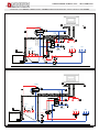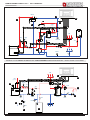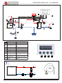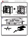
1
ISTRUZIONI PER L’INSTALLAZIONE, L’USO E LA MANUTENZIONE - IT
INSTRUCTIONS FOR INSTALLATION, USE AND MAINTENANCE - EN
ANWEISUNGEN FÜR DIE AUFSTELLUNG, DEN GEBRAUCH UND DIE WARTUNG - DE
INSTRUCTIONS POUR L’INSTALLATION, L’UTILISATION ET L’ENTRETIEN – FR
TERMOSUPREMA COMPACT DSA / ITALY TERMO DSA
Testata secondo / Tested according to / Geprüft nach / Certifié selon / : EN13240
|
IT – PER EVITARE DANNI ALL’APPARECCHIO, RISPETTARE IL CARICO ORARIO DI COMBUSTIBILE INDICATO
NEL PRESENTE LIBRETTO.
EN – TO AVOID DAMAGES TO THE APPLIANCE, PLEASE RESPECT THE MAX. FUEL QUANTITY (KG/HR)
INDICATED IN THE USER’S MANUAL.
DE – UM SCHÄDEN AN DEM GERÄT ZU VERMEIDEN, BITTE BEACHTEN SIE DIE BRENNSTOFFMENGE (KG/H)
LT. BEDIENUNGSANLEITUNG.
FR – POUR EVITER DES DOMMAGES A L’APPAREIL RESPECTER LA QUANTITE’ MAX. DE COMBUSTIBLE (KG/H)
COMME INDIQUE DANS LA NOTICE D’UTILISATION.
NORME DI SICUREZZA SUGLI APPARECCHI
Per il rispetto delle norme di sicurezza è obbligatorio installare
e utilizzare i nostri prodotti seguendo scrupolosamente le indicazioni fornite nel presente manuale.
SAFETY REGULATIONS ON THE APPLIANCES
To meet safety regulations, it is compulsory to install and use our products
carefully following the instructions contained in this manual.
SICHERHEITSVORSCHRIFTEN BEI DEN AUSRÜSTUNGEN
Um die Sicherheitsvorschriften zu beachten, ist es notwendig, unsere Produkte
vorsichtig nach den in diesem Handbuch enthaltenen Anweisungen zu installieren und anzuwenden.
RÉGLÉS DE SÉCURITÉ SUR LES APPAREILS
Selon les normes de sécurité sur les appareils l’acheteur
et le commerçant sont contraints de s’informer sur le fonctionnement correct sur la base des instructions d’emploi.
TERMOSUPREMA COMPACT DSA / ITALY TERMO DSA
DICHIARAZIONE DI CONFORMITA’ DEL COSTRUTTORE
Oggetto: Assenza di amianto e cadmio
Si dichiara che tutti i nostri apparecchi vengono assemblati con materiali che non presentano parti di amianto o suoi derivati
e che nel materiale d’apporto utilizzato per le saldature non è presente/utilizzato in nessuna forma il cadmio, come previsto
dalla norma di riferimento.
Oggetto: Regolamento CE n. 1935/2004
Si dichiara che in tutti gli apparecchi da noi prodotti, i materiali destinati a venire a contatto con i cibi sono adatti all’uso
alimentari, in conformità al Regolamento CE in oggetto.
DECLARATION OF CONFORMITY OF THE MANUFACTURER
Object: Absence of asbestos and cadmium
We declare that the materials used for the assembly of all our appliances are without asbestos parts or asbestos derivates
and that in the material used for welding, cadmium is not present, as prescribed in relevant norm.
Object: CE n. 1935/2004 regulation.
We declare that in all products we produce, the materials which will get in touch with food are suitable for alimentary use,
according to the a.m. CE regulation.
KONFORMITÄTSERKLÄRUNG DES HERSTELLERS
Betreff: Fehlen von Asbest und Kadmium
Wir bestätigen, dass die verwendeten Materialen oder Teilen für die Herstellung der La Nordica Geräte ohne Asbest und
Derivat sind und auch das Lot für das Schweißen immer ohne Kadmium ist.
Betreff: Ordnung CE n. 1935/2004.
Wir erklären in alleiniger Verantwortung, dass die Materialen der Teile, die für den Kontakt mit Lebensmitteln vorgesehen
sind, für die Nahrungsbenutzung geeignet sind und der Richtlinien CE n. 1935/2004 erfüllen.
DÉCLARATION DE CONFORMITÉ DU CONSTRUCTEUR
Objet: Absence d’amiante et de cadmium
Nous déclarons que tous nos appareils sont assemblés avec des matériaux ne comportant pas de parties en amiante ou ses
dérivés et que dans le matériau d’apport utilisé pour les soudures le cadmium n’est pas présent ni utilisé sous aucune forme
que ce soit, comme il est prévu par la norme de référence.
Objet: Règlement CE n. 1935/2004
Nous déclarons que tous nos produits, les matériaux destinés à entrer en contact avec les aliments sont indiqués pour
l’usage des aliments, conformément au Règlement CE cité à l’objet.
7095802 - IT - EN - DE - FR 3
TERMOSUPREMA COMPACT DSA / ITALY TERMO DSA
1.
2.
3.
4.
5.
6.
7.
8.
9.
10.
11.
12.
13.
14.
1.
2.
3.
4.
5.
6.
7.
8.
9.
10.
11.
12.
13.
14.
4
IT - INDICE
DATI TECNICI............................................................................................................................................................................................................6
AVVERTENZE GENERALI .......................................................................................................................................................................................7
NORME PER L’INSTALLAZIONE.............................................................................................................................................................................7
3.1. Vaso di espansione APERTO..........................................................................................................................................................................7
3.2. Vaso di espansione CHIUSO...........................................................................................................................................................................8
3.3. VALVOLA MISCELATRICE TERMOSTATICA AUTOMATICA (fornita come OPTIONAL)...............................................................................8
3.4. VALVOLA SCARICO TERMICO (fornita come OPTIONAL)............................................................................................................................8
3.5. COLLEGAMENTO E CARICO DELL’IMPIANTO.............................................................................................................................................9
SICUREZZA ANTINCENDIO.....................................................................................................................................................................................9
4.1. PRONTO INTERVENTO..................................................................................................................................................................................9
DESCRIZIONE TECNICA..........................................................................................................................................................................................9
CANNA FUMARIA...................................................................................................................................................................................................10
6.1. COMIGNOLO................................................................................................................................................................................................. 11
6.2. COLLEGAMENTO AL CAMINO..................................................................................................................................................................... 11
6.3. COLLEGAMENTO ALLA CANNA FUMARIA DI UN CAMINETTO O FOCOLARE APERTO........................................................................ 11
AFFLUSSO D’ARIA NEL LUOGO D’INSTALLAZIONE DURANTE LA COMBUSTIONE..................................................................................... 11
COMBUSTIBILI AMMESSI / NON AMMESSI.........................................................................................................................................................12
ACCENSIONE..........................................................................................................................................................................................................12
FUNZIONAMENTO NORMALE...............................................................................................................................................................................13
10.1. USO DEL FORNO (dove presente)...............................................................................................................................................................13
10.2. MANCANZA DI ENERGIA ELETTRICA.........................................................................................................................................................13
10.3. FUNZIONAMENTO NEI PERIODI DI TRANSIZIONE...................................................................................................................................14
10.4. UTILIZZO ESTIVO DEL PRODOTTO............................................................................................................................................................14
FERMO ESTIVO.......................................................................................................................................................................................................14
MANUTENZIONE E CURA......................................................................................................................................................................................14
12.1. LE MAIOLICHE..............................................................................................................................................................................................14
12.2. PRODOTTI IN PIETRA OLLARE...................................................................................................................................................................14
12.3. PRODOTTI VERNICIATI................................................................................................................................................................................14
12.4. PRODOTTI SMALTATI...................................................................................................................................................................................15
12.5. COMPONENTI CROMATI.............................................................................................................................................................................15
12.6. CENTRINO E CERCHI .................................................................................................................................................................................15
12.7. PULIZIA VETRO............................................................................................................................................................................................15
12.8. PULIZIA CASSETTO CENERE.....................................................................................................................................................................15
12.9. PULIZIA CANNA FUMARIA...........................................................................................................................................................................15
12.10.MANUTENZIONE DELL’IMPIANTO IDRAULICO..........................................................................................................................................15
SCHEMA DI INSTALLAZIONE................................................................................................................................................................................26
13.1. SCHEDA TECNICA valvola termostatica VST...............................................................................................................................................31
DIMENSIONI............................................................................................................................................................................................................37
EN - CONTENTS
TECHNICAL DATA...................................................................................................................................................................................................16
GENERAL PRECAUTIONS.....................................................................................................................................................................................17
INSTALLATION REGULATIONS.............................................................................................................................................................................17
3.1. OPEN expansion Tank system.......................................................................................................................................................................17
3.2. CLOSED expansion Tank system..................................................................................................................................................................18
3.3. AUTOMATIC THERMOSTATIC MIXER VALVE - (purchased as OPTIONAL part)........................................................................................18
3.4. HEAT DISCHARGE VALVE - (purchased as OPTIONAL part) .....................................................................................................................18
3.5. SYSTEM CONNECTION AND FILLING........................................................................................................................................................19
FIRE SAFETY..........................................................................................................................................................................................................19
4.1. IN A EMERGENCY........................................................................................................................................................................................19
TECHNICAL DESCRIPTION...................................................................................................................................................................................19
FLUE........................................................................................................................................................................................................................20
6.1. CHIMNEY POT..............................................................................................................................................................................................21
6.2. CONNECTION TO THE CHIMNEY...............................................................................................................................................................21
6.3. CONNECTING A FIREPLACE OR OPEN HEARTH TO THE FLUE.............................................................................................................21
AIR FLOW IN THE PLACE OF INSTALLATION DURING COMBUSTION ...........................................................................................................21
ALLOWED / NOT ALLOWED FUELS.....................................................................................................................................................................22
LIGHTING.................................................................................................................................................................................................................22
NORMAL OPERATION............................................................................................................................................................................................23
10.1. USE OF THE OVEN (If present)....................................................................................................................................................................23
10.2. ELECTRICAL POWER SUPPLY FAILURE....................................................................................................................................................23
10.3. OPERATION IN TRANSITION PERIODS . ...................................................................................................................................................23
10.4. SUMMER USE...............................................................................................................................................................................................24
SUMMER STOP.......................................................................................................................................................................................................24
MAINTENANCE AND CARE...................................................................................................................................................................................24
12.1. MAJOLICAS...................................................................................................................................................................................................24
12.2. PRODUCTS MADE OF NATURAL STONE . ................................................................................................................................................24
12.3. VARNISHED PRODUCTS ............................................................................................................................................................................24
12.4. ENAMELLED PRODUCTS............................................................................................................................................................................24
12.5. CHROMIUM-COMPONENTS........................................................................................................................................................................25
12.6. CAST IRON TOP and the HOT PLATES.......................................................................................................................................................25
12.7. GLASS CLEANING........................................................................................................................................................................................25
12.8. CLEANING OUT THE ASHES.......................................................................................................................................................................25
12.9. CLEANING THE FLUE..................................................................................................................................................................................25
12.10.MAINTENANCE ON THE WATER SYSTEM.................................................................................................................................................25
INSTALLATION LAY-OUT.......................................................................................................................................................................................26
13.1. Thermostatic Valve VTS TECHNICAL DATA SHEET.....................................................................................................................................31
DIMENSIONS...........................................................................................................................................................................................................37
7095802 - IT - EN - DE - FR
TERMOSUPREMA COMPACT DSA / ITALY TERMO DSA
7095802 - IT - EN - DE - FR 5
TERMOSUPREMA COMPACT DSA / ITALY TERMO DSA
1. DATI TECNICI
TERMOSUPREMA
COMPACT - DSA
ITALY TERMO - DSA
A1
1
Potenza termica globale in kW
22.3
22.3
Potenza termica nominale (utile) in kW
18.5
18.5
Potenza resa al liquido (H2O) in kW
15
15
Potenza resa all’ambiente in kW
3.5
3.5
Consumo orario legna in kg/h (legna con 20% umidità)
5.2
5.2
Rendimento in %
83
83
0.12
0.12
160 S/P
160 S/P
Canna fumaria altezza - dimensioni in mm (#)
5m – 220x220 Ø220
5m – 220x220 Ø220
Contenuto fluido scambiatore (H2O) in L (litri)
22
22
17 - 20 (1.7 - 2.0)
17 - 20 (1.7 - 2.0)
Allacciamento caldaia (Ø)
1 ”F gas
1 ”F gas
Tubo scarico automatico (Ø)
½”M gas
½”M gas
Presa aria esterna in mm (Ø)
200
200
Emissione gas di scarico in g/s – legna
21
21
Temperatura gas di scarico nel mezzo in °C - legna
176
176
70-75
70-75
VA 1,5 bar - VEC 3 bar
VA 1,5 bar - VEC 3 bar
Dimensioni bocca fuoco in mm (L x H)
233 x 160
233 x 160
Dimensioni focolare in mm (L x H x P)
257 x 350 x 407
257 x 350 x 407
Dimensioni forno in mm (L x H x P)
307 x 418 x 430
307 x 418 x 430
Definizione: termoprodotto secondo EN 12815
Sistema costruttivo
CO misurato al 13% di ossigeno in %
Diametro scarico fumi in mm
Depressione al camino (tiraggio) in Pa (mm H2O)
Temperatura ottimale di esercizio in °C
Pressione max d’esercizio in bar (vaso espansione Aperto - Chiuso)
Tipo di griglia
Movibile - piana
Altezza in mm
860
861
Larghezza in mm
982
965
Profondità (con maniglie) in mm
682
690
Peso in Kg
293
272
Distanze di sicurezza antincendio
Capitolo SICUREZZA
(#) Diametro 200 mm utilizzabile con canna fumaria non inferiore a 6 m
Per edifici il cui isolamento non corrisponde alle disposizioni sulla protezione del calore, il volume di riscaldamento è:
(30 Kcal/h x m3) - tipo di costruzione favorevole: 530 m³
(40 Kcal/h x m ) - tipo di costruzione meno favorevole: 400 m³
(50 Kcal/h x m3) - tipo di costruzione sfavorevole: 320 m³
3
Con un isolamento termico secondo le norme sul risparmio energetico il volume riscaldato è maggiore.
Con un riscaldamento temporaneo, in caso di interruzioni superiori a 8h, la capacità di riscaldamento diminuisce del 25% circa.
IMPORTANTE: La potenza dell’impianto termico collegato, deve essere commisurata alla potenza ceduta all’acqua dal termoprodotto;
un carico troppo ridotto non consente un regolare funzionamento del forno, mentre un carico troppo elevato impedisce un adeguato
riscaldamento dei radiatori.
6
7095802 - IT - EN - DE - FR
TERMOSUPREMA COMPACT DSA / ITALY TERMO DSA
2. AVVERTENZE GENERALI
La responsabilità de La NORDICA S.p.A. è limitata alla fornitura dell’apparecchio.
Il suo impianto va realizzato in modo conforme alla regola dell’arte, secondo le prescrizioni delle presenti istruzioni e le regole della
professione, da personale qualificato, che agisce a nome di imprese adatte ad assumere l’intera responsabilità dell’insieme dell’impianto.
La NORDICA S.p.A. non è responsabile del prodotto modificato senza autorizzazione e tanto meno per l’uso di ricambi non
originali. NON SI POSSONO EFFETTUARE MODIFICHE ALL’APPARECCHIO. Non vi sarà responsabilità da parte di La NORDICA
S.p.A. in caso di mancato rispetto di tali precauzioni.
Questo apparecchio non è adatto all’uso da parte di persone (inclusi bambini) con capacità fisiche, sensoriali e mentali ridotte, o inesperte,
a meno che non vengano supervisionate ed istruite nell’uso dell’apparecchio da una persona responsabile per la loro sicurezza. I bambini
devono essere controllati per assicurarsi che non giochino con l’apparecchio (EN 60335-2-102 / 7.12).
E’ OBBLIGATORIO rispettare norme nazionali ed europee, disposizioni locali o in materia edilizia, nonché regolamentazioni
antincendio.
3. NORME PER L’INSTALLAZIONE
L’installazione del prodotto e degli equipaggiamenti ausiliari, relativi all’impianto di riscaldamento, deve essere conforme a tutte le Norme
e Regolamentazioni attuali ed a quanto previsto dalla Legge.
L’installazione, i relativi collegamenti dell’impianto, la messa in servizio e la verifica del corretto funzionamento devono essere eseguiti
a regola d’arte da personale professionalmente preparato nel pieno rispetto delle norme vigenti, sia nazionali, regionali, provinciali e
comunali presenti nel paese in cui è stato installato l’apparecchio, nonché delle presenti istruzioni.
L’installazione deve essere eseguita da personale autorizzato, che dovrà rilasciare all’acquirente una dichiarazione di conformità
dell’impianto, il quale si assumerà l’intera responsabilità dell’installazione definitiva e del conseguente buon funzionamento del prodotto
installato. Prima dell’installazione eseguire le seguenti verifiche:
• Accertarsi che il pavimento possa sostenere il peso dell’apparecchio e provvedere ad un adeguato isolamento nel caso sia costruito
in materiale infiammabile.
• Assicurarsi che nella stanza dove sarà installato vi sia una ventilazione adeguata, a tale proposito è fondamentale prestare attenzione
a finestre e porte con chiusura stagna (guarnizioni di tenuta)
• Evitare l’installazione in locali con presenza di condotti di ventilazione collettivo, cappe con o senza estrattore, apparecchi a gas di tipo
B, pompe di calore o la presenza di apparecchi il cui funzionamento contemporaneo possa mettere in depressione il locale (rif. Norma
UNI 10683)
• Accertarsi che la canna fumaria e i tubi a cui verrà collegato l’apparecchio siano idonei. Non è consentito il collegamento di più
apparecchi allo stesso camino.
• Il diametro dell’apertura per il collegamento al camino deve corrispondere per lo meno al diametro del tubo fumo. L’apertura dovrebbe
essere dotata di una connessione a muro per l’inserimento del tubo di scarico e di un rosone.
• Il foro di scarico fumi non utilizzato deve essere chiuso con il relativo tappo (vedi capitolo SCHEDE TECNICHE).
• L’installazione deve prevedere l’accesso alle operazioni di pulizia e manutenzione del prodotto e della canna fumaria.
Prima dell’installazione, si consiglia di effettuare un lavaggio accurato di tutte le tubazioni dell’impianto onde rimuovere eventuali residui
che potrebbero compromettere il buon funzionamento del termoprodotto.
IMPORTANTE:
a) E’ opportuno installare una valvola di sfiato (manuale o automatica) per permettere di togliere aria dall’impianto.
b) In caso di fuoriuscite d’acqua chiudere l’alimentazione idrica ed avvisare con sollecitudine il servizio tecnico di assistenza;
c) La pressione di esercizio dell’impianto deve essere periodicamente controllata.
d) In caso di non utilizzo della caldaia per un lungo periodo è consigliabile l’intervento del servizio tecnico di assistenza per effettuare
almeno le seguenti operazioni: - chiudere i rubinetti dell’acqua sia dell’impianto termico sia del sanitario; - svuotare l’impianto termico
e sanitario se c’è rischio di gelo.
I termoprodotti modello DSA possono essere installati sia in un impianto a VASO di espansione APERTO (cap.3.1) sia in un impianto a
VASO di espansione CHIUSO (cap.3.2).
La NORDICA S.p.A. declina ogni responsabilità per danni a cose e/o persone provocati dall’impianto. Inoltre non è responsabile
del prodotto modificato senza autorizzazione e tanto meno per l’uso di ricambi non originali. Il Vostro abituale spazzacamino di
zona deve essere informato sull’installazione del prodotto, affinché possa verificarne il regolare collegamento alla canna fumaria ed il
grado di efficienza di quest’ultima.
3.1. Vaso di espansione APERTO
L’impianto con vaso di espansione aperto, deve essere OBBLIGATORIAMENTE provvisto di:
1. VASO DI ESPANSIONE APERTO: vaso avente una capacità pari al 10 % del contenuto d’acqua totale del termoprodotto e dell’impianto.
Il vaso va posizionato nel punto più alto dell’impianto almeno 2 m sopra il radiatore posto al livello più alto.
2. TUBO DI SICUREZZA : tubo che collega per la via più breve, senza tratti discendenti o sifonanti, la mandata del termoprodotto con la
parte superiore del vaso di espansione aperto. ATTENZIONE : il diametro interno del tubo di mandata che collega il termoprodotto al
vaso di espansione aperto deve essere uguale al diametro interno del connettore di mandata presente nel termo prodotto. Il suddetto
tubo di collegamento deve essere privo d’intercettazioni.
3. TUBO DI CARICO : tubo che collega il fondo del vaso di espansione aperto con il tubo di ritorno dell’impianto. La sezione minima
deve essere di ¾”gas. Tutti questi elementi non devono per nessuna ragione avere organi di intercettazione interposti che possano
accidentalmente escluderli e devono essere posizionati in ambienti non esposti al gelo poiché, se dovessero gelare, si potrebbe
verificare la rottura o addirittura l’esplosione del corpo caldaia. In caso di esposizione al gelo sarà opportuno aggiungere all’acqua
dell’impianto una adeguata percentuale di liquido antigelo che consentirà di eliminare completamente il problema. In nessun modo ci
dovrà essere circolazione d’acqua nel vaso di espansione aperto fra il tubo di sicurezza ed il tubo di carico. Questa provocherebbe
l’ossigenazione dell’acqua e la conseguente corrosione del termoprodotto e dell’impianto in tempi molto brevi
4. VALVOLA DI SCARICO TERMICO: costituisce una ulteriore sicurezza positiva in grado di prevenire l’ebollizione anche in assenza
7095802 - IT - EN - DE - FR 7
TERMOSUPREMA COMPACT DSA / ITALY TERMO DSA
di energia elettrica. E’ costituita da un corpo valvola simile ad una valvola di sicurezza a pressione che, a differenza di questa, si apre
al raggiungimento di una temperatura pretarata ( di solito 94 – 95° C ) scaricando dalla mandata dell’impianto acqua calda che verrà
sostituita con altrettanta acqua fredda proveniente attraverso il tubo di carico del vaso di espansione aperto smaltendo in questo modo
il calore eccessivo
5. VALVOLA DI SICUREZZA da 1,5 bar: la massima pressione di esercizio ammessa per l’impianto è di 1,5 bar (pari a 15 m di colonna
d’acqua), pressioni superiori possono provocare deformazioni e rotture al corpo caldaia.
6. ALTRI DISPOSITIVI di sicurezza previsti dalla Normativa vigente in materia.
7. POMPA DI CIRCOLAZIONE : deve essere preferibilmente montata sul ritorno per evitare che possa disinnescarsi a temperature
dell’acqua molto elevate, accertarsi però che non faccia circolare l’acqua nel vaso di espansione aperto altrimenti provocherebbe una
continua ossigenazione dell’acqua con conseguente, rapida, corrosione del corpo caldaia. La sua prevalenza deve essere tale da non
provocare una circolazione forzata nel vaso di espansione aperto. Deve inoltre essere collegata ad un termostato o alla centralina
elettronica fornita come OPTIONAL.
8. VALVOLA MISCELATRICE TERMOSTATICA AUTOMATICA – (vedi capitolo 3.3)
ATTENZIONE: i sensori di sicurezza della temperatura devono essere installati a bordo macchina o ad una distanza non maggiore di
30 cm dal collegamento di mandata del termoprodotto. Qualora i termoprodotti non siano provvisti di tutti i dispostivi, quelli mancanti
possono essere installati sulla tubazione di mandata del termoprodotto entro una distanza dal termoprodotto non maggiore di 1
m. Tutti questi elementi non devono per nessuna ragione avere organi di intercettazione interposti che possano accidentalmente
escluderli e devono essere posizionati in ambienti non esposti al gelo poiché, se dovessero gelare, si potrebbe verificare la rottura o
addirittura l’esplosione del corpo caldaia.
ATTENZIONE: Per nessuna ragione si deve accendere il fuoco se prima l’impianto non sia stato completamente riempito d’acqua;
il farlo comporterebbe un danneggiamento gravissimo di tutta la struttura. Il riempimento dell’impianto deve essere fatto tramite
il tubo di carico direttamente nella vaschetta del vaso di espansione aperto in modo da evitare che una eccessiva pressione della rete
idrica deformi il corpo caldaia.
L’impianto va tenuto costantemente pieno d’acqua anche nei periodi in cui non è richiesto l’uso. Durante il periodo invernale un’eventuale
non attivit-à va affrontata con l’aggiunta di sostanze antigelo.
3.2. Vaso di espansione CHIUSO
L’impianto con vaso di espansione CHIUSO, deve essere OBBLIGATORIAMENTE provvisto di:
1. VALVOLA DI SICUREZZA da 3 bar: la massima pressione di esercizio ammessa per l’impianto è di 3 bar (pari a 30 m di colonna
d’acqua), pressioni superiori possono provocare deformazioni e rotture del corpo caldaia. ATTENZIONE : il diametro interno del tubo
di mandata che collega il termoprodotto alla valvola di sicurezza deve essere uguale al diametro interno del connettore di mandata
presente nel termo prodotto. Il suddetto tubo di collegamento deve essere privo d’intercettazioni.
2. VALVOLA MISCELATRICE TERMOSTATICA AUTOMATICA – (vedi capitolo 3.3)
3. VALVOLA DI SCARICO TERMICO o VALVOLA DI SCARICO DI SICUREZZA TERMICA, con sensore a doppia sicurezza
4. VASO DI ESPANSIONE CHIUSO collegato sul ritorno del termoprodotto. ATTENZIONE: il diametro interno del tubo di ritorno che
collega il termoprodotto al vaso di espansione chiuso deve essere uguale al diametro interno del connettore di ritorno presente nel
termo prodotto. Il suddetto tubo di collegamento deve essere privo d’intercettazioni.
5. TERMOSTATO DI COMANDO DEL CIRCOLATORE
6. TERMOSTATO DI ATTIVAZIONE DELL’ALLARME ACUSTICO
7. ALLARME ACUSTICO
8. INDICATORE DI TEMPERATURA
9. INDICATORE DI PRESSIONE
10. SISTEMA DI CIRCOLAZIONE
ATTENZIONE: i sensori di sicurezza della temperatura devono essere installati a bordo macchina come indicato al capitolo 3.3.Tutti
questi elementi non devono per nessuna ragione avere organi di intercettazione interposti che possano accidentalmente escluderli e
devono essere posizionati in ambienti non esposti al gelo poiché, se dovessero gelare, si potrebbe verificare la rottura o addirittura
l’esplosione del corpo caldaia.
OBBLIGATORIAMENTE i termoprodotti per il riscaldamento di tipo domestico inseriti in impianti di riscaldamento a VASO CHIUSO
devono essere dotati, al loro interno, di un circuito di raffreddamento predisposto dal costruttore dell’apparecchio, attivato da una valvola
di sicurezza termica (vedi capitolo 3.4) che non richieda energia ausiliaria e tale da garantire che non venga superata la temperatura
limite imposta dalla norma. Il collegamento tra il gruppo di alimentazione e la valvola deve essere privo di intercettazioni. La pressione a
monte del circuito di raffreddamento deve essere di almeno 1,5 bar.
3.3. VALVOLA MISCELATRICE TERMOSTATICA AUTOMATICA (fornita come OPTIONAL)
La valvola miscelatrice termostatica automatica trova applicazione nei termoprodotti a combustibile solido in quanto previene il ritorno di
acqua fredda nello scambiatore Figura 1 a pagina 30. Le tratte 1 e 3 sono sempre aperte e, assieme alla pompa installata sul ritorno (R),
garantiscono la circolazione dell’acqua all’interno dello scambiatore della caldaia a biomassa (CB). Una elevata temperatura di ritorno
permette di migliorare l’efficienza, riduce la formazione di condensa dei fumi e allunga la vita della caldaia. Le valvole in commercio
presentano svariate tarature, La NORDICA consiglia l’utilizzo del modello 55°C con connessioni idrauliche da 1”. Una volta raggiunta la
temperatura di taratura della valvola, viene aperta la tratta 2 e l’acqua della caldaia va all’impianto attraverso la mandata (M). IMPORTANTE
la mancata installazione del dispositivo fa decadere la garanzia dello scambiare di calore.
3.4. VALVOLA SCARICO TERMICO (fornita come OPTIONAL)
I termoprodotti a combustibile solido devono essere installati con le sicurezze previste dalle vigenti leggi in materia. A tale scopo la
termostufa è munita di uno serpentino di scarico termico.
Il serpentino di scarico termico dovrà essere collegato da un lato alla rete idrica (A - Figura 1 a pagina 30 - Cap. SCHEDE TECNICHE)
e dall’altro alla rete di drenaggio (C). La valvola di scarico termico, il cui bulbo andrà collegato all’attacco B, al raggiungimento della
8
7095802 - IT - EN - DE - FR
TERMOSUPREMA COMPACT DSA / ITALY TERMO DSA
temperatura di sicurezza abilita l’ingresso di acqua fredda nel serpentino contenuto nella caldaia, scaricando l’eccesso termico tramite il
tubo C verso uno scarico opportunamente installato. La pressione a monte del circuito di raffreddamento deve essere di almeno 1,5 bar.
3.5. COLLEGAMENTO E CARICO DELL’IMPIANTO
Alcuni esempi, puramente indicativi dell’impianto, sono riportati al capitolo SCHEMA DI INSTALLAZIONE, mentre i collegamenti al
termoprodotto sono riportati al capitolo SCHEDE TECNICHE.
ATTENZIONE :Il riempimento dell’impianto deve avvenire esclusivamente per caduta naturale dell’acqua dal vaso di espansione
aperto attraverso il tubo di carico per evitare che una pressione di rete troppo elevata dell’acquedotto possa deformare o far
scoppiare il corpo caldaia.
Durante questa fase aprire tutti gli sfiati dei termosifoni per evitare formazioni di sacche d’aria, sorvegliando poi la fuori uscita d’acqua per
evitare spiacevoli allagamenti.
Il collaudo di tenuta dell’impianto va eseguito con la pressione del vaso di espansione aperto.
L’impianto va tenuto costantemente pieno d’acqua anche nei periodi in cui non è richiesto l’uso del termoprodotto. Durante il
periodo invernale un’eventuale non attività va affrontata con l’aggiunta di sostanze antigelo.
4. SICUREZZA ANTINCENDIO
Nell’installazione del prodotto devono essere osservate le seguenti misure di sicurezza:
a) Al fine di assicurare un sufficiente isolamento termico, rispettare la distanza minima di sicurezza dal retro e da entrambi i lati da
elementi costruttivi ed oggetti infiammabili e sensibili al calore (mobili, rivestimenti di legno, stoffe ecc.) (vedi Figura 5 a pagina 35 - A).
Tutte le distanze minime di sicurezza sono indicate sulla targhetta tecnica del prodotto e NON si deve scendere al di sotto
dei valori indicati;
b) Davanti alla porta del focolare, nell’area di radiazione della stessa non deve esserci alcun oggetto o materiale di costruzione infiammabile
e sensibile al calore a meno di 100 cm di distanza. Tale distanza può essere ridotta a 40 cm qualora venga installata una protezione,
retroventilata e resistente al calore, davanti all’intero componente da proteggere;
c) Qualora il prodotto sia installato su un pavimento di materiale infiammabile, bisogna prevedere un sottofondo ignifugo. I pavimenti in
materiale infiammabile, come moquette, parquet o sughero etc., devono essere sostituiti da uno strato di materiale non infiammabile,
ad esempio ceramica, pietra, vetro o acciaio etc. (dimensioni secondo l’ordinamento regionale). Nel caso in cui la sostituzione del
pavimento non sia possibile, l’apparecchio deve essere posizionato sopra una lastra di pietra o cemento spessa almeno 12
cm. Il sottofondo deve sporgere frontalmente di almeno 50 cm e lateralmente di almeno altri 30 cm rispetto l’apertura della porta di
carico (vedi Figura 5 a pagina 35 - B);
d) Sopra al prodotto non devono essere presenti componenti infiammabili (es. mobili - pensili).
Il prodotto deve funzionare esclusivamente con il cassetto cenere inserito. I residui solidi della combustione (ceneri) devono essere raccolti
in un contenitore ermetico e resistente al fuoco. Il prodotto non deve mai essere acceso in presenza di emissioni gassose o vapori (per
esempio colla per Linoleum, benzina ecc.). Non depositate materiali infiammabili nelle vicinanze del prodotto .
Durante la combustione viene sprigionata energia termica che comporta un marcato riscaldamento delle superfici, di porte, maniglie,
comandi, vetri, tubo fumi ed eventualmente della parte anteriore dell’apparecchio. Evitate il contatto con tali elementi senza un
corrispondente abbigliamento protettivo o senza utensili accessori (guanti resistenti al calore, dispositivi di comando).
Fate in modo che i bambini siano consapevoli di questi pericoli e teneteli lontani dal focolare durante il suo funzionamento.
Quando si utilizza un combustibile errato o troppo umido si formano dei depositi (creosoto) nella canna fumaria con il rischio d’incendio.
4.1. PRONTO INTERVENTO
Se si manifesta un incendio nel collegamento o nella canna fumaria :
a) Chiudere la porta di caricamento e del cassetto cenere.
b) Chiudere i registri dell’aria comburente
c) Spegnere tramite l’uso di estintori ad anidride carbonica ( CO2 a polveri )
d) Richiedere l’immediato intervento dei Vigili del Fuoco
NON SPEGNERE IL FUOCO CON L’USO DI GETTI D’ACQUA.
Quando la canna fumaria smette di bruciare bisogna farla verificare da uno specialista per individuare eventuali crepe o punti permeabili.
5. DESCRIZIONE TECNICA
I termoprodotti La Nordica si addicono a riscaldare spazi abitativi dotati di un impianto di riscaldamento centralizzato costituito da radiatori
o da termoconvettori sostituendo del tutto o in parte la tradizionale caldaia a gas o gasolio. Esse sono ideali per appartamenti di vacanza
e case del fine settimana oppure come riscaldamento ausiliario durante tutto l’anno.
Come combustibili vengono utilizzati ceppi di legna.
La termocucina è costituita di lastre in lamiera d’acciaio zincata, ghisa smaltata. Il focolare si trova all’interno della caldaia costruita con
acciaio di 4 mm di spessore e rinforzata con chiodi saldati. Nella caldaia circola l’acqua dell’impianto di riscaldamento la quale assorbe il
calore prodotto nel focolare. All’interno del focolare si trova una griglia piana regolabile in altezza.
Il focolare è dotato di una porta panoramica con vetro ceramico (resistente fino a 700°C). Questo consente un’affascinante vista sulle
fiamme ardenti. Inoltre viene così impedita ogni possibile fuori uscita di scintille e fumo.
Il riscaldamento dell’ambiente avviene:
a) Per irraggiamento: attraverso il vetro panoramico e le superfici esterne calde del termoprodotto viene irraggiato calore nell’ambiente.
b) Per conduzione: mediante i radiatori o termoconvettori dell’impianto centralizzato alimentati dall’acqua calda generata dal
termoprodotto.
Il termoprodotto è fornito di registri per l’aria primaria e secondaria e di un termostato, con i quali viene regolata l’aria di combustione.
7095802 - IT - EN - DE - FR 9
TERMOSUPREMA COMPACT DSA / ITALY TERMO DSA
Registro Aria PRIMARIA (Figura 7 a pagina 36 pos. A).
Con il registro inferiore viene regolato il passaggio dell’aria primaria nella parte bassa attraverso il cassetto cenere e la griglia in direzione
del combustibile. L’aria primaria è necessaria per il processo di combustione. Il cassetto cenere deve essere svuotato regolarmente, in
modo che la cenere non ostacoli l’entrata dell’aria per la combustione. Attraverso l’aria primaria viene anche mantenuto vivo il fuoco.
Il registro dell’aria primaria deve rimanere aperto non più di ¼ durante la combustione a legna, altrimenti questa arde troppo velocemente
e il termo prodotto si può surriscaldare.
Registro Aria SECONDARIA (Figura 7 a pagina 36 pos. B).
Questo pomello deve essere aperto (quindi totalmente spostato verso destra) in particolare per la combustione di legna (vedi Tabella)
L’aria secondaria, passando tra il doppio vetro della porta fuoco, si riscalda ed innesca la doppia combustione mantenendo nello stesso
tempo il vetro pulito (registro aperto).
TERMOSTATO automatico (Figura 7 a pagina 36 pos. C)
Il termostato ha la funzione di aumentare o diminuire automaticamente la combustione.
A seconda della posizione scelta, il termostato agirà sulla valvola che regola l’immissione dell’aria nel focolare, posta sulla schiena della
cucina. Ruotare in senso orario dallo 0 al 5 per ravvivare il fuoco e dal 5 allo 0 in senso antiorario per ridurre la combustione. Trattandosi
di un dispositivo di elevata precisione si raccomanda di ruotare con cura e di non forzare mai la manopola.
Registro FUMI (Figura 7 a pagina 36 pos. D)
(Conversione dalla funzione di cucina - USO PIASTRA - USO FORNO a quella di cucina uso RISCALDAMENTO)
Nella parte centrale del cruscotto si trova il registro-fumi, riconoscibile da un pomello smaltato e contrassegnato.
Quando si posiziona il registro a SX (sul simbolo pentola), i gas di combustione fluiscono sopra ed attorno al forno (funzione cucina - USO
PIASTRA – USO FORNO); quando invece si posiziona a DX (sul simbolo dell’acqua), i gas fluiscono vicino alla caldaia aumentando
uniformemente la temperatura favorendo il riscaldamento dell’acqua al suo interno (funzione cucina USO RISCALDAMENTO).
Registro ACCENSIONE (Figura 7 a pagina 36 pos. E).
Sulla facciata della cucina, tra il corrimano di protezione e il registro fumi, si trova la leva di comando del registro di accensione, riconoscibile
da un pomolo cromato. Questo registro va utilizzato solo per facilitare l’accensione del combustibile nella caldaia, tirare la leva verso
l’esterno della cucina (registro aperto). IMPORTANTE : durante il normale funzionamento della cucina, la leva del registro deve rimanere
tutta inserita (spinta verso l’interno della cucina) in questo modo si evita un consumo eccessivo del combustibile ed una scarsa resa della
termocucina (registro chiuso).
Per accendere il fuoco seguire quanto segue (vedi capitolo ACCENSIONE) :
• Aprire il registro accensione per agevolare lo scarico dei fumi, (aprire anche l’eventuale valvola a farfalla posta sul tubo di scarico fumi) .
• Posizionare la manopola del termostato sulla posizione 5 (massima apertura).
• Aprire il registro dell’aria primaria (posto sulla porta cenere).
• Dopo aver innescato il fuoco con piccoli pezzi di legna e aspettato che sia ben acceso, regolare il termostato sulla pozione corrispondente
al calore desiderato (0÷5).
• Portare il registro fumi nella posizione forno.
• Chiudere il registro accensione ( ..e l’eventuale valvola a farfalla posta sul tubo di scarico fumi) .
La regolazione dei registri necessaria in fase di accensione è la seguente:
Registro Aria PRIMARIA
Registro Aria SECONDARIA
Termostato
TERMOSUPREMA CPT - DSA
APERTO
APERTO
5
ITALY TERMO - DSA
APERTO
APERTO
5
La regolazione dei registri necessaria per l’ottenimento della resa calorifica nominale è la seguente (vedi capitolo DATI TECNICI):
Registro Aria PRIMARIA
Registro Aria SECONDARIA
Termostato
TERMOSUPREMA CPT - DSA
MAX 1/4 APERTO
APERTO
3
ITALY TERMO - DSA
MAX 1/4 APERTO
APERTO
3
6. CANNA FUMARIA
Requisiti fondamentali per un corretto funzionamento dell’apparecchio:
• la sezione interna deve essere preferibilmente circolare;
• essere termicamente isolata ed impermeabile e costruita con materiali idonei a resistere al calore, ai prodotti della combustione ed
alle eventuali condense;
• essere priva di strozzature ed avere andamento verticale con deviazioni non superiori a 45°;
• se già usata deve essere pulita;
• rispettare i dati tecnici del manuale di istruzioni;
Qualora le canne fumarie fossero a sezione quadrata o rettangolare gli spigoli interni devono essere arrotondati con raggio non inferiore
a 20 mm. Per la sezione rettangolare il rapporto massimo tra i lati deve essere ≤ 1,5.
Una sezione troppo piccola provoca una diminuzione del tiraggio. Si consiglia un’altezza minima di 4 m.
Sono VIETATE e pertanto pregiudicano il buon funzionamento dell’apparecchio: fibrocemento, acciaio zincato, superfici interne ruvide e
porose. In Figura 2 a pagina 33 sono riportati alcuni esempi di soluzione.
La sezione minima deve essere di 4 dm2 (per esempio 20x20 cm) per gli apparecchi il cui diametro di condotto è inferiore a 200
mm, o 6,25 dm2 (per esempio 25x25 cm) per gli apparecchi con diametro superiore a 200 mm.
Il tiraggio creato dalla vostra canna fumaria deve essere sufficiente ma non eccessivo.
10
7095802 - IT - EN - DE - FR
TERMOSUPREMA COMPACT DSA / ITALY TERMO DSA
Una sezione della canna fumaria troppo importante può presentare un volume troppo grande da riscaldare e dunque provocare delle
difficoltà di funzionamento dell’apparecchio; per evitare ciò provvedete ad intubare la stessa per tutta la sua altezza. Una sezione troppo
piccola provoca una diminuzione del tiraggio.
La canna fumaria deve essere adeguatamente distanziata da materiali infiammabili o combustibili mediante un opportuno
isolamento o un’intercapedine d’aria.
E’ VIETATO far transitare all’interno della stessa tubazioni di impianti o canali di adduzione d’aria. E’ proibito inoltre praticare aperture
mobili o fisse, sulla stessa, per il collegamento di ulteriori apparecchi diversi (vedi capitolo COLLEGAMENTO ALLA CANNA FUMARIA DI
UN CAMINETTO O FOCOLARE APERTO).
6.1. COMIGNOLO
Il tiraggio della canna fumaria dipende anche dall’idoneità del comignolo.
È pertanto indispensabile che, se costruito artigianalmente, la sezione di uscita sia più di due volte la sezione interna della canna fumaria
(Figura 3 a pagina 33).
Dovendo sempre superare il colmo del tetto, il comignolo dovrà assicurare lo scarico anche in presenza di vento (Figura 4 a pagina 34).
Il comignolo deve rispondere ai seguenti requisiti:
• Avere sezione interna equivalente a quella del camino.
• Avere sezione utile d’uscita doppia di quella interna della canna fumaria.
• Essere costruito in modo da impedire la penetrazione nella canna fumaria di pioggia, neve e di qualsiasi corpo estraneo.
• Essere facilmente ispezionabile, per eventuali operazioni di manutenzione e pulizia.
6.2. COLLEGAMENTO AL CAMINO
I prodotti con chiusura automatica della porta (tipo 1) devono obbligatoriamente funzionare, per motivi di sicurezza, con la porta del
focolare chiusa (fatta eccezione per la fase di carico del combustibile o l’eventuale rimozione della cenere).
I prodotti con le porte non a chiusura automatica (tipo 2) devono essere collegate ad una propria canna fumaria. Il funzionamento con porta
aperta è consentito soltanto previa sorveglianza.
Il tubo di collegamento alla canna fumaria deve essere più corto possibile, rettilineo orizzontale o leggermente in salita, ed a tenuta stagna.
Il collegamento deve essere eseguito con tubi stabili e robusti (Vi consigliamo uno spessore di 2 mm) ed essere fissato ermeticamente
alla canna fumaria. Il diametro interno del tubo di collegamento deve corrispondere al diametro esterno del tronchetto di scarico fumi della
cucina (DIN 1298).
ATTENZIONE: per quanto riguarda la realizzazione del collegamento alla canna fumaria e i materiali infiammabili attenersi a quanto
previsto dalla Norma UNI10683.
IMPORTANTE: il foro di scarico fumi non utilizzato deve essere ricoperto con il relativo tappo (Capitolo: SCHEDA TECNICA pos.A).
La depressione al camino (TIRAGGIO) deve essere di almeno 17-20 Pascal (=1.7-2 mm di colonna d’acqua). La misurazione deve
essere fatta sempre ad apparecchio caldo (resa calorifica nominale). Quando la depressione supera i 20 Pascal è necessario ridurla con
l’installazione di un regolatore di tiraggio supplementare (valvola a farfalla) sul tubo di scarico o nel camino , come da normative vigenti.
Per un buon funzionamento dell’apparecchio è essenziale che nel luogo d’installazione venga immessa sufficiente aria per la combustione
(vedi capitolo 7).
6.3. COLLEGAMENTO ALLA CANNA FUMARIA DI UN CAMINETTO O FOCOLARE APERTO
Il canale fumi è il tratto di tubo che collega il Prodotto alla canna fumaria, nel collegamento devono essere rispettati questi semplici ma
importantissimi principi:
• Per nessuna ragione si dovrà usare il canale fumo avente un diametro inferiore a quello del collarino di uscita di cui è dotato il
Prodotto;
• Ogni metro di percorso orizzontale del canale fumo provoca una sensibile perdita di carico che dovrà eventualmente essere
compensata con un innalzamento della canna fumaria;
• Il tratto orizzontale non dovrà comunque mai superare i 2 metri (UNI 10683-2005);
• Ogni curva del canale fumi riduce sensibilmente il tiraggio della canna fumaria che dovrà essere eventualmente compensata
innalzandola adeguatamente;
• La Normativa UNI 10683-2005 – ITALIA prevede che le curve o variazioni di direzione non devono in nessun caso essere superiori a
2 compresa l’immissione in canna fumaria.
Volendo usare la canna fumaria di un caminetto o focolare aperto, sarà necessario chiudere ermeticamente la cappa al di sotto del punto
di imbocco del canale fumo pos. A Figura 6 a pagina 35.
Se poi la canna fumaria è troppo grande (p.e. cm 30x40 oppure 40x50) è necessario intubarla con un tubo di acciaio Inox di almeno
200mm di diametro, pos. B, avendo cura di chiudere bene lo spazio rimanente fra il tubo e la canna fumaria immediatamente sotto al
comignolo pos. C.
7. AFFLUSSO D’ARIA NEL LUOGO D’INSTALLAZIONE DURANTE LA COMBUSTIONE
Poiché questi prodotti ricavano l’aria di combustione dal locale di installazione, è OBBLIGATORIO che nel luogo stesso venga immessa
una sufficiente quantità d’aria. In caso di finestre e porte a tenuta stagna (es. Case costruite con il criterio di risparmio energetico) è
possibile che l’ingresso di aria fresca non venga più garantito e questo compromette il tiraggio dell’apparecchio, il vostro benessere e la
vostra sicurezza. Bisogna pertanto garantire una alimentazione aggiuntiva di aria fresca mediante una presa d’aria esterna posta nelle
vicinanze dell’apparecchio oppure tramite la posa di una conduttura per l’aria di combustione che porti verso l’esterno od in un vicino locale
aerato, ad eccezione del locale caldaia o garage (VIETATO).
L’entrata dell’aria per la combustione nel luogo d’installazione non deve essere ostruita durante il funzionamento del Prodotto. E’
assolutamente necessario che negli ambienti, in cui vengono fatti funzionare prodotti con un tiraggio naturale del camino, venga immessa
tanta aria quanta ne è necessaria per la combustione, ossia fino a 25 m³/ora. Il naturale ricircolo dell’aria deve essere garantito da alcune
aperture fisse verso l’esterno, la loro grandezza è stabilita da relative normative in materia. Chiedete informazioni al Vostro spazzacamino
di fiducia. Le aperture devono essere protette con delle griglie e non devono mai essere otturate. Una cappa di estrazione (aspirante)
7095802 - IT - EN - DE - FR 11
TERMOSUPREMA COMPACT DSA / ITALY TERMO DSA
installata nella stessa stanza od in una confinante provoca una depressione nell’ambiente. Questo provoca la fuori uscita di gas combusti
(fumo denso, odore); è dunque necessario assicurare un maggiore afflusso di aria fresca.
La depressione di una cappa aspirante può, nella peggiore delle ipotesi, trasformare la canna fumaria del Prodotto in presa d’aria
esterna risucchiando i fumi nell’ambiente con conseguenze gravissime per le persone.
8. COMBUSTIBILI AMMESSI / NON AMMESSI
I combustibili ammessi sono ceppi di legna. Si devono utilizzare esclusivamente ceppi di legna secca (contenuto d’acqua max. 20%).
Si dovrebbero caricare al massimo 2 o 3 ceppi di legna. I pezzi di legna dovrebbero avere una lunghezza di ca. 20-30 cm ed una
circonferenza di massimo 30-35 cm.
I tronchetti di legno pressati non resinati devono essere usati con cautela per evitare surriscaldamenti dannosi all’apparecchio,
in quanto questi hanno un potere calorifico elevato.
La legna usata come combustibile deve avere un contenuto d’umidità inferiore al 20% e deve essere deposta in luogo asciutto. La
legna umida rende l’accensione più difficile, poiché è necessaria una maggiore quantità d’energia per far evaporare l’acqua presente.
Il contenuto umido ha inoltre lo svantaggio che, con l’abbassarsi della temperatura, l’acqua si condensa prima nel focolare e quindi nel
camino causando un notevole deposito di fuliggine con successivo possibile rischio d’incendio della stessa.
La legna fresca contiene circa il 60% di H2O, perciò non è adatta ad essere bruciata. Bisogna collocarla in luogo asciutto e ventilato (per
esempio sotto una tettoia) per almeno due anni prima di utilizzarla.
Tra gli altri NON possono essere bruciati: carbone, ritagli, cascami di corteccia e pannelli, legna umida o trattata con vernici,
materiali di plastica; in tal caso decade la garanzia sull’apparecchio.
Carta e cartone devono essere utilizzati solo per l’accensione.
La combustione di rifiuti è VIETATA e danneggerebbe inoltre l’apparecchio e la canna fumaria, provocando inoltre danni alla salute ed
in virtù del disturbo olfattivo a reclami da parte del vicinato .
La legna non è un combustibile a lunga durata e pertanto non è possibile un riscaldamento continuo durante la notte.
Specie
Kg/mc
kWh/kg Umidità 20%
Faggio
750
4,0
Cerro
900
4,2
Olmo
640
4,1
Pioppo
470
4,1
Larice*
660
4,4
Abete rosso*
450
4,5
Pino silvestre*
550
4,4
*
LEGNI RESINOSI POCO ADATTI
ATTENZIONE: L’uso continuo e prolungato di legna particolarmente ricca di oli aromatici (p.e. Eucalipto, Mirto, etc.) provoca il
deterioramento (sfaldamento) repentino dei componenti in ghisa presenti nel prodotto.
9. ACCENSIONE
ATTENZIONE: Per nessuna ragione si deve accendere il fuoco se prima l’impianto non sia stato completamente riempito d’acqua;
il farlo comporterebbe un danneggiamento gravissimo di tutta la struttura. IN MANCANZA TOTALE O PARZIALE D’ACQUA
NON ACCENDERE ASSOLUTAMENTE IL FUOCO NEL TERMOPRODOTTO (NEANCHE PER PROVA) IN QUANTO POTREBBE
ROVINARSI IRRIMEDIABILMENTE, IN TAL CASO DECADE LA GARANZIA SULL’APPARECCHIO.
IMPORTANTE: alla prima accensione è inevitabile che venga prodotto un odore sgradevole (dovuto dall’essiccamento dei collanti presenti
nella cordicella di guarnizione o dalle vernici protettive), il quale sparisce dopo un breve utilizzo. Si deve comunque assicurare una
buona ventilazione dell’ambiente. Alla prima accensione Vi consigliamo di caricare una quantità ridotta di combustibile e di aumentare
lentamente la resa calorifica dell’apparecchio.
Per una corretta prima accensione dei prodotti trattati con vernici per alte temperature, occorre sapere quanto segue:
• i materiali di costruzione dei prodotti in questione non sono omogenei, infatti coesistono parti in ghisa e in acciaio.
• la temperatura alla quale il corpo del prodotto è sottoposto non è omogenea: da zona a zona si registrano temperature variabili dai
300 °C ai 500 °C;
• durante la sua vita, il prodotto è sottoposto a cicli alternati di accensioni e di spegnimento durante la stessa giornata e a cicli di intenso
utilizzo o di assoluto riposo al variare delle stagioni;
• prima di potersi definire rodato, il prodotto nuovo dovrà essere sottoposto a diversi cicli di avviamento per poter consentire a tutti i
materiali ed alla vernice di completare le varie sollecitazioni elastiche;
• in particolare inizialmente si potrà notare l’emissione di odori tipici dei metalli sottoposti a grande sollecitazione termica e di vernice
ancora fresca. Tale vernice, sebbene in fase di costruzione venga cotta a 250°C per qualche ora, dovrà superare più volte e per una
certa durata la temperatura di 350°C, prima di incorporarsi perfettamente con le superfici metalliche
Diventa quindi importante seguire questi piccoli accorgimenti in fase di accensione:
1. Assicuratevi che sia garantito un forte ricambio d’aria nel luogo dove è installato l’apparecchio.
2. Nelle prime accensioni, non caricare eccessivamente la camera di combustione (circa metà della quantità indicata nel manuale
d’istruzioni) e tenere il prodotto acceso per almeno 6-10 ore di continuo, con i registri meno aperti di quanto indicato nel manuale
d’istruzioni.
12
7095802 - IT - EN - DE - FR
TERMOSUPREMA COMPACT DSA / ITALY TERMO DSA
3. Ripetere questa operazione per almeno 4-5 o più volte, secondo la Vostra disponibilità.
4. Successivamente caricare sempre più (seguendo comunque quanto descritto sul libretto di istruzione relativamente al massimo carico)
e tenere possibilmente lunghi i periodi di accensione evitando, almeno in questa fase iniziale, cicli di accensione-spegnimento di breve
durata.
5. Durante le prime accessioni nessun oggetto dovrebbe essere appoggiato sull’apparecchio ed in particolare sulle superfici
laccate. Le superfici laccate non devono essere toccate durante il riscaldamento.
6. Una volta superato il “rodaggio” si potrà utilizzare il Vostro prodotto come il motore di un’auto, evitando bruschi riscaldamenti con
eccessivi carichi.
Per accendere il fuoco consigliamo di usare piccoli listelli di legno con carta oppure altri mezzi di accensione in commercio.
È VIETATO l’uso di tutte le sostanze liquide come per es. alcool, benzina, petrolio e simili.
ATTENZIONE: durante le prime accensioni potrà avvenire una consistente condensazione dei fumi con una piccola fuori uscita
d’acqua dal termoprodotto; questo è un fenomeno destinato a sparire in brevissimo tempo, se invece dovesse risultare
persistente sarà necessario far controllare il tiraggio della canna fumaria.
Le aperture per l’aria (primaria e secondaria) devono essere aperte contemporaneamente solo un po’ (si deve aprire anche l’eventuale
registro di accensione, e valvola a farfalla posta sul tubo di scarico fumi). Quando la legna comincia ad ardere si può ricaricare aprendo
lentamente la porta, in modo da evitare fuori uscite di fumo, si chiude il registro dell’aria primaria e si controlla la combustione mediante
l’aria secondaria secondo le indicazioni riportate nel capitolo DATI TECNICI.
Durante questa fase, non lasciare mai il focolare senza supervisione.
Mai sovraccaricare l’apparecchio (consultare la tabella tecnica - quantità max. di combustibile caricabile / consumo orario). Troppo
combustibile e troppa aria per la combustione possono causare surriscaldamento e quindi danneggiare l’apparecchio. La garanzia non
copre i danni dovuti al surriscaldamento dell’apparecchio. Non accendere mai l’apparecchio quando ci sono gas combustibili
nella stanza.
10. FUNZIONAMENTO NORMALE
Dopo aver posizionato i registri correttamente inserire la carica di legna oraria indicata, evitare sovraccarichi che provocano sollecitazioni
anomale e deformazioni. Bisogna sempre usare il prodotto con la porta chiusa per evitare danneggiamenti dovuti all’eccessivo
surriscaldamento (effetto forgia). La non osservanza di tale regola fa decadere la garanzia.
Gli apparecchi con chiusura automatica della porta (tipo 1) devono obbligatoriamente funzionare, per motivi di sicurezza, con la porta del
focolare chiusa (fatta eccezione per la fase di carico del combustibile o l’eventuale rimozione della cenere ).
Gli apparecchi con le porte non a chiusura automatica (tipo 2) devono essere collegati ad una propria canna fumaria. Il funzionamento con
porta aperta è consentito soltanto sotto sorveglianza.
IMPORTANTE: Per motivi di sicurezza la porta del focolare può essere aperta solo durante il caricamento di combustibile. Il
focolare deve rimanere chiuso durante il funzionamento ed i periodi di non-utilizzo.
Con i registri viene regolata l’emissione di calore del focolare. Essi devono essere aperti secondo il bisogno calorifico. La migliore
combustione (con emissioni minime) viene raggiunta quando, caricando legna, la maggior parte dell’aria per la combustione passa
attraverso il registro dell’aria secondaria. Non si deve mai sovraccaricare l’apparecchio.
Troppo combustibile e troppa aria per la combustione possono causare surriscaldamento e quindi danneggiare la stufa, in particolare si
potrebbero verificare delle rotture sulla parte inferiore della facciata. I danni causati da surriscaldamento non sono coperti da garanzia.
Bisogna pertanto usare il prodotto sempre con la porta chiusa per evitare danneggiamenti dovuti all’eccessivo surriscaldamento (effetto
forgia). La regolazione dei registri necessaria per l’ottenimento della resa calorifica nominale con una depressione al camino di 17-20
Pa (1,7-2 mm di colonna d’acqua) è la seguente: vedi capitolo DESCRIZIONE TECNICA. Questo è un apparecchio a combustione
intermittente.
Nel caso che la temperatura dell’acqua superi la temperatura d’intervento delle sicurezze, sospendere immediatamente il
carico di legna, verificare la diminuzione della temperatura dell’acqua e della fiamma eliminando le cause del surriscaldamento
(chiudere eventualmente il registro d’aria).
Qualora nel termoprodotto sia collegata l’acqua sanitaria si può aprire il rubinetto dell’acqua calda per velocizzare il raffreddamento
dell’apparecchio stesso.
Oltre che dalla regolazione dell’aria per la combustione, l’intensità della combustione e quindi la resa calorifica è influenzata dal camino.
Un buon tiraggio del camino richiede una minore quantità d’aria per la combustione, mentre uno scarso tiraggio necessita di una maggiore
quantità d’aria per la combustione.
Per verificare la buona combustione, controllate se il fumo che esce dal camino è trasparente. Se è bianco significa che l’apparecchio non
è regolato correttamente o la legna è troppo bagnata; se invece il fumo è grigio o nero è segno che la combustione non è completa (è
necessaria una maggior quantità di aria secondaria).
10.1. USO DEL FORNO (dove presente)
Grazie all’apporto d’aria per la combustione la temperatura del forno può essere sensibilmente influenzata. Un sufficiente tiraggio al
camino e dei canali ben puliti per il flusso dei fumi roventi attorno al forno sono fondamentali per un buon risultato di cottura.
La padella forno può essere collocata su diversi piani. Torte spesse e arrosti grandi sono da inserire al livello più basso. Torte piatte e
biscotti vanno al livello medio. Il livello superiore può essere utilizzato per riscaldare o rosolare.
Questo prodotto è dotato di una griglia focolare in ghisa sollevabile tramite un’apposita manovella. La posizione superiore della griglia
ottimizza l’uso della piastra mentre quella inferiore ottimizza il riscaldamento dell’acqua e del forno (vedi Figura 9 a pagina 36).
10.2. MANCANZA DI ENERGIA ELETTRICA
Nella eventualità di una improvvisa interruzione dell’energia elettrica durante il normale funzionamento dell’impianto, sarà necessario
compiere queste semplici manovre per evitare che il termoprodotto vada in ebollizione in seguito al mancato funzionamento della pompa.
1. Alzare al massimo la griglia mobile del focolare (dove presente) per ridurre la superficie di scambio esposta al calore della fiamma.
2. Chiudere i registri dell’aria primaria e secondaria nonché portare in posizione 0 il termostato (dove presente).
3. Aprire la porta del forno (dove presente) in modo da favorire lo smaltimento del calore interno.
4. Aprire il registro fumi; in questo modo si devierà verso il camino il calore residuo ancora prodotto.
7095802 - IT - EN - DE - FR 13
TERMOSUPREMA COMPACT DSA / ITALY TERMO DSA
10.3. FUNZIONAMENTO NEI PERIODI DI TRANSIZIONE
Durante il periodo di transizione, ovvero quando le temperature esterne sono più elevate, o in caso di improvviso aumento della temperatura
si possono avere dei disturbi alla canna fumaria che fanno si che i gas combusti non vengono aspirati completamente. I gas di scarico non
fuoriescono più completamente (odore intenso di gas).
In tal caso scuotete più frequentemente la griglia e aumentate l’aria per la combustione. Caricate in seguito una quantità ridotta di
combustibile facendo sì che questo bruci più rapidamente (con sviluppo di fiamme ) e si stabilizzi così il tiraggio della canna fumaria.
Controllate quindi che tutte le aperture per la pulizia e i collegamenti al camino siano ermetici. In caso di incertezza rinunciate all’utilizzo
della stufa.
ATTENZIONE: Per nessuna ragione si dovrà accendere il fuoco prima che l’impianto non sia stato completamente riempito d’acqua; il
farlo comporterebbe un danneggiamento gravissimo a tutta la struttura. L’impianto va tenuto costantemente pieno d’acqua anche nei
periodi in cui non è richiesto l’uso del termoprodotto. Durante il periodo invernale un’eventuale non attività va affrontata con l’aggiunta
di sostanze antigelo.
10.4. UTILIZZO ESTIVO DEL PRODOTTO.
Volendo utilizzare la termocucina solamente per la cottura dei cibi, ad esempio durante il periodo estivo, bisogna: - alzare al massimo
la griglia mobile in modo da escludere il più possibile le superfici di scambio in grado di cedere calore all’acqua Figura 9 a pagina 36;
- il registro fumi andrà tenuto aperto in modo da favorire la fuoriuscita dei fumi caldi dopo aver scaldato la piastra in ghisa (funzione
cucina - USO PIASTRA ); - Mantenere l’impianto completamente riempito d’acqua. L’assenza di acqua nell’impianto comporterebbe
un danneggiamento gravissimo di tutta la struttura.
Onde evitare l’ebollizione dell’acqua nella caldaia, la pompa di circolazione dell’impianto dovrà essere SEMPRE in funzione per poter
smaltire sui radiatori, o sul puffer, o su qualsiasi altra struttura di assorbimento termico il calore ceduto all’acqua dalla caldaia. Se la pompa
non dovesse circolare o, per qualsiasi ragione la temperatura dell’acqua dovesse superare i 95°C interviene la valvola del D.S.A.
scaricando calore tramite acqua a perdere. Si raccomanda di monitorare la temperatura dell’acqua nel termoprodotto durante
l’uso estivo per evitare interventi ripetuti della valvola DSA che ne potrebbero compromettere il buon funzionamento.
ATTENZIONE: Per nessuna ragione si deve accendere il fuoco se prima l’impianto non sia stato completamente riempito d’acqua;
il farlo comporterebbe un danneggiamento gravissimo di tutta la struttura.
11. FERMO ESTIVO
Dopo aver effettuato la pulizia del focolare, del camino e della canna fumaria, provvedendo all’eliminazione totale della cenere ed altri
eventuali residui, è opportuno chiudere tutte le porte con i relativi registri focolare. Nel caso in cui l’apparecchio venga disconnesso dal
camino, è opportuno chiudere il foro di uscita.
E’ consigliabile effettuare l’operazione di pulizia della canna fumaria almeno una volta all’anno; verificando nel contempo l’effettivo stato
delle guarnizioni che se non risultassero perfettamente integre - cioè non più aderenti alla stufa - non garantirebbero il buon funzionamento
dell’apparecchio! Si renderebbe quindi necessaria la loro sostituzione.
In caso di umidità del locale dove è posto l’apparecchio, sistemare dei sali assorbenti all’interno del focolare.
Proteggere le parti in ghisa, se si vuole mantenere inalterato nel tempo l’aspetto estetico, con della vaselina neutra.
Verificare il livello dell’acqua del vaso di espansione e fare uscire l’eventuale aria dell’impianto sfiatando i radiatori, verificare inoltre la
funzionalità degli accessori idraulici ed elettrici (centralina, circolatore).
ATTENZIONE: Per nessuna ragione si dovrà accendere il fuoco prima che l’impianto non sia stato completamente riempito d’acqua; il farlo
comporterebbe un danneggiamento gravissimo a tutta la struttura. L’impianto va tenuto costantemente pieno d’acqua anche nei periodi
in cui non è richiesto l’uso del termoprodotto.
12. MANUTENZIONE E CURA
Controllare e pulire, almeno una volta all’anno, la presa d’aria esterna. Il camino deve essere regolarmente ramazzato dallo spazzacamino.
Fate controllare dal Vostro spazzacamino responsabile di zona la regolare installazione del prodotto, il collegamento al camino e l’aerazione.
IMPORTANTE: La manutenzione deve essere eseguita esclusivamente ad apparecchio freddo. Si possono usare esclusivamente
parti di ricambio espressamente autorizzate ed offerte da La NORDICA . In caso di bisogno Vi preghiamo di rivolgerVi al Vs rivenditore
specializzato. L’ APPARECCHIO NON PUÒ ESSERE MODIFICATO!
12.1. LE MAIOLICHE
Le maioliche La NORDICA sono prodotti di alta fattura artigianale e come tali possono presentare micro-puntinature, cavillature ed
imperfezioni cromatiche. Queste caratteristiche ne testimoniano la pregiata natura.
Smalto e maiolica, per il loro diverso coefficiente di dilatazione, producono microscrepolature (cavillatura) che ne dimostrano l’effettiva
autenticità.
Per la pulizia delle maioliche si consiglia di usare un panno morbido ed asciutto; se si usa un qualsiasi detergente o liquido, quest’ultimo
potrebbe penetrare all’interno dei cavilli evidenziandoli.
12.2. PRODOTTI IN PIETRA OLLARE
La pietra ollare va pulita con della carta abrasiva molto fine o una spugna abrasiva. NON utilizzare alcun detergente o liquido.
12.3. PRODOTTI VERNICIATI
Dopo anni di utilizzo del prodotto, la variazione di colore dei particolari verniciati è un fenomeno del tutto normale. Questo fenomeno è
dovuto alle notevoli escursioni di temperatura a cui il prodotto è soggetto quando è in funzione e all’invecchiamento della vernice stessa
con il passare del tempo.
AVVERTENZA: prima dell’eventuale applicazione della nuova vernice, bisogna pulire e rimuovere ogni residuo dalla superficie da verniciare.
14
7095802 - IT - EN - DE - FR
TERMOSUPREMA COMPACT DSA / ITALY TERMO DSA
12.4. PRODOTTI SMALTATI
Per la pulizia delle parti smaltate usare acqua saponata o detergenti NON abrasivi o chimicamente NON aggressivi, a freddo.
Dopo la pulizia NON lasciare asciugare l’acqua saponata o il detergente, provvedere alla loro rimozione immediatamente.
NON usare carta vetrata o paglietta in ferro.
12.5. COMPONENTI CROMATI
Qualora i componenti cromati dovessero diventare azzurrognoli a causa di un surriscaldamento, ciò può essere risolto con un adeguato
prodotto per la pulizia.
12.6. CENTRINO E CERCHI
Il centrino (cucine a legna) ed i cerchi (cucine - stufe ) vanno periodicamente carteggiati con carta vetrata grana 150. NO parti smaltate.
12.7. PULIZIA VETRO
Tramite uno specifico ingresso dell’aria secondaria la formazione di deposito di sporco, sul vetro della porta, viene efficacemente rallentata.
Non può comunque mai essere evitata con l’utilizzo dei combustibili solidi (es. legna umida ) e questo non è da considerarsi come un
difetto dell’apparecchio .
IMPORTANTE: la pulizia del vetro panoramico deve essere eseguita solo ed esclusivamente a apparecchio freddo per evitarne
l’esplosione. Per la pulizia si possono usare dei prodotti specifici oppure, con una palla di carta di giornale (quotidiano) inumidita e
passata nella cenere. Non usare comunque panni, o prodotti abrasivi o chimicamente aggressivi.
La corretta procedura di accensione, l’utilizzo di quantità e tipi di combustibili idonei, il corretto posizionamento del registro dell’aria
secondaria, il sufficiente tiraggio del camino e la presenza dell’aria comburente sono indispensabili per il funzionamento ottimale
dell’apparecchio e per mantenere pulito il vetro.
ROTTURA DEI VETRI: i vetri essendo in vetroceramica resistenti fino ad uno sbalzo termico di 750°C, non sono soggetti a
shock termici. La loro rottura può essere causata solo da shock meccanici (urti o chiusura violenta della porta ecc.). Pertanto la
sostituzione non è in garanzia.
12.8. PULIZIA CASSETTO CENERE
Tutti i prodotti La NORDICA hanno una griglia focolare ed un cassetto per la raccolta della ceneri.
Vi consigliamo di svuotare periodicamente il cassetto dalla cenere e di evitarne il riempimento totale, per non surriscaldare la griglia. Inoltre
Vi consigliamo di lasciare sempre 3-4 cm di cenere nel focolare.
ATTENZIONE: le ceneri tolte dal focolare vanno riposte in un recipiente di materiale ignifugo dotato di un coperchio stagno. Il
recipiente va posto su di un pavimento ignifugo, lontano da materiali infiammabili fino allo spegnimento e raffreddamento
completo delle ceneri.
12.9. PULIZIA CANNA FUMARIA
La corretta procedura di accensione, l’utilizzo di quantità e tipi di combustibili idonei, il corretto posizionamento del registro dell’aria
secondaria, il sufficiente tiraggio del camino e la presenza d’aria comburente sono indispensabili per il funzionamento ottimale
dell’apparecchio e per mantenere pulito il vetro.
Almeno una volta l’anno è consigliabile eseguire una pulizia completa, o qualora sia necessario (problemi di mal funzionamento con
scarsa resa). Un eccessivo deposito di fuliggine (creosoto) può provocare problemi nello scarico dei fumi e l’incendio della canna
fumaria. La pulizia deve essere eseguita esclusivamente ad apparecchio freddo. Questa operazione, dovrebbe essere svolta da uno
spazzacamino che contemporaneamente può effettuare un’ispezione.
12.10.MANUTENZIONE DELL’IMPIANTO IDRAULICO
Un eccessivo deposito di incrostazioni sulle pareti interne del focolare riduce notevolmente l’efficienza dello scambio termico, pertanto
quando necessario bisogna asportare le incrostazioni mediante una spatola d’acciaio. Non usare mai sostanze corrosive che possono
danneggiare il termoprodotto e la caldaia.
Ad impianto spento, una volta all’anno, eseguire le seguenti verifiche:
• controllare la funzionalità e l’efficienza delle valvole di scarico termico e di sicurezza. Qualora queste fossero difettose contattare
l’installatore autorizzato. E’ TASSATIVAMENTE VIETATO LA RIMOZIONE O MANOMISSIONE DI TALI SICUREZZE.
• Verificare l’isolamento termico del tubo di riempimento e del tubo di sicurezza.
• Accertarsi che l’impianto sia carico ed in pressione, controllare il livello dell’acqua all’interno del vaso di espansione, e verificarne la
funzionalità assicurandosi anche dell’efficienza del tubo di sicurezza.
7095802 - IT - EN - DE - FR 15
TERMOSUPREMA COMPACT DSA / ITALY TERMO DSA
1. TECHNICAL DATA
TERMOSUPREMA
COMPACT - DSA
ITALY TERMO - DSA
A1
1
Global thermal power in kW
22.3
22.3
Nominal thermal power in kW
18.5
18.5
Power given back to water in kW
15
15
Power given back to the room in kW
3.5
3.5
Hourly wood consumption in kg / h (wood with 20% humidity)
5.2
5.2
Efficiency in %
83
83
0.12
0.12
160 S/P
160 S/P
5m – 220x220 Ø220
5m – 220x220 Ø220
22
22
17 - 20 (1.7 - 2.0)
17 - 20 (1.7 - 2.0)
Boiler connections (Ø)
1 ”F gas
1 ”F gas
Automatic discharge pipe diameter (Ø)
½”M gas
½”M gas
Outer air inlet Ø in mm
200
200
Exhaust gas emission in g/s – wood
21
21
Exhaust gas temperature in °C - wood
176
176
70-75
70-75
VA 1,5 bar - VEC 3 bar
VA 1,5 bar - VEC 3 bar
233 x 160
233 x 160
Hearth size in mm (W x H x D)
257 x 350 x 407
257 x 350 x 407
Oven size in mm (W x H x D)
307 x 418 x 430
307 x 418 x 430
Definition: in accordance with EN 12815
Constructive system
CO measured at 13% oxygen in %
Smoke outlet diameter in mm
Chimney height - dimension in mm (#)
Fluid contents of the exchanger in L (litres)
Chimney draught in Pa (mm H2O)
Optimal working temperature in °C
Max. working pressure in bar (expansion vessel Open - Closed)
Hearth opening size in mm (W x H)
Movable - flat
Type of grill
Height in mm
860
861
Width in mm
982
965
Depth (with handles) in mm
682
690
Weight in Kg
293
272
Chapter SAFETY
Fire prevention safety distances
(#) 200 mm diameter can be used with flue of no less than 6 m
For those buildings in which the thermal insulation does not correspond to the instructions on heat protection, the heating volume of the
product is:
(30 Kcal/h x m3) - favourable type of building: 530 m³
(40 Kcal/h x m ) - less favourable type of building: 400 m³
(50 Kcal/h x m ) - unfavourable type of building: 320 m³
3
3
With thermal insulation in accordance with the regulations regarding energy saving, the heated volume is greater. With temporary heating,
in the event of interruptions which last more than 8 hours, the heating capacity is reduced by about 25%.
IMPORTANT: The power of the connected heating system must be proportional to the power transferred to the water by the thermoproduct;
a charge which is too low does not allow regular oven operation, while a charge which is too high prevents adequate
radiator heating.
16
7095802 - IT - EN - DE - FR
TERMOSUPREMA COMPACT DSA / ITALY TERMO DSA
2. GENERAL PRECAUTIONS
La NORDICA S.p.A. responsibility is limited to the supply of the appliance.
The installation must be carried out scrupulously according to the instructions provided in this manual and the rules of the profession.
Installation must only be carried out by a qualified technician who works on behalf of companies suitable to assume the entire responsibility
of the system as a whole.
La NORDICA S.p.A. declines any responsibility for the product that has been modified without written authorisation as well as for
the use of non-original spare parts. NO MODIFICATIONS CAN BE CARRIED OUT TO THE APPLIANCE. NORDICA S.p.A. cannot
be held responsible for lack of respect for such precautions.
This appliance is not suitable for the use of inexperienced people (included children) or with physical, sensorial and mental reduced
capacities. They have to be controlled and educated in the use of the appliance from a responsible person for their security. The children
have to be controlled to be sure that they would not play with the appliance. (EN 60335-2-102/7.12).
It is OBLIGATORY to respect the National and European rules, local regulations concerning building matter and also fireproof
rules.
3. INSTALLATION REGULATIONS
Installation of the product and auxiliary equipment in relation to the heating system must comply with all current Standards and Regulations
and to those envisioned by the law.
The installation and the relating to the connections of the system, the commissioning and the check of the correct functioning must
be carried out in compliance with the regulations in force by authorised professional personnel with the requisites required by the law,
being national, regional, provincial or town council present in the country within which the appliance is installed, besides these present
instructions.
Installation must be carried out by authorised personnel who must provide the buyer with a system declaration of conformity and will
assume full responsibility for final installation and as a consequence the correct functioning of the installed product.
Before installing the appliance, carry out the following checks:
• Make sure that the floor can support the weight of the appliance, and if it is made of flammable material, provide suitable insulation.
• Make sure that there is adequate ventilation in the room where the appliance is to be installed, with particular attention to windows
and doors with tight closing (seal ropes).
• Do not install the appliance in rooms containing collective ventilation ducts, hoods with or without extractor, type B gas appliances,
heat pumps, or other appliances that, operating at the same time, can put the room in depression (ref. UNI 10683 standard)
• Make sure that the flue and the pipes to which the appliance will be connected are suitable for its operation. It is not allowed the
connection of various appliances to the same chimney.
• The diameter of the opening for connection to the chimney must at least correspond to the diameter of the flue gas pipe. The opening
must be equipped with a wall connection for the insertion of the exhaust pipe and a rosette.
• The unused flue gas exhaust stub pipe must be covered with its respective cap (see chapter TECHNICAL DATA SHEETS).
• The installation must be appropriate and has to allow the cleaning and maintenance of the product and the flue.
Before installation, accurately wash the pipes of the system in order to remove any residuals that could compromise the correct functioning
of the appliance.
IMPORTANT:
a) It would be appropriate to install an automatic or manual air valve to allow the air outlet from the plumbing system;
b) In case of water leaking, close the water supply and promptly warn the after sales technical service;
c) The system working pressure must periodically be checked.
d) If not using the boiler for a long period of time, it is recommended that the after sales technical service is contacted to carry out at least
the following operations:
•close the water taps of both the thermal system and the domestic hot water system;
•empty the thermal system and the domestic hot water system if there is risk of freezing.
The DSA thermo appliances, can be installed in both an OPEN expansion Tank system (see chapter 3.1) and a CLOSED expansion Tank
system (see chapter 3.2).
LA NORDICA S.p.A. declines all responsibility for damage to things and/or persons caused by the system. In addition, it is not
responsible for any product modified without authorisation and even less for the use of non original spare parts.
Your regular local chimney sweep must be informed about the installation of the appliance so that he can check the correct connection to
the chimney.
3.1. OPEN expansion Tank system
It is COMPULSORY that the OPEN expansion Tank system is provided with:
1.
2.
3.
OPEN EXPANSION Tank: which has a capacity of 10% of total water content of thermo-product and of the installation. This is
installed at the highest point of the system, at least 2 m over the radiator that is at the highest level.
SAFETY PIPE : that connects through the shortest way, without descending or siphoning parts, the delivery of thermo-product to
the upper side of open expansion tank. ATTENTION: The inside diameter of the supply pipe which connects the thermoproduct with
the open expansion vessel must be equal to the internal diameter of the supply junction present in the thermoproduct. The above
mentioned connection pipe must be without siphoning parts.
LOAD PIPE : which connects the bottom of open expansion tank with the return pipe of installation. The minimum diameter must
be ¾” gas. All those parts must no have for any reason meditate intercept bodies that could accidentally exclude them and must be
placed in rooms which are protected from frost. On the contrary, if they freeze, the boiler body could break or even explode. In case
of frost placing it will be right to add a proper percentage of antifreeze liquid to the water of installation in order to delete the whole
7095802 - IT - EN - DE - FR 17
TERMOSUPREMA COMPACT DSA / ITALY TERMO DSA
4.
5.
6.
7.
8.
problem. In no way there must be water circulation in the open expansion tank between the safety and loading pipe. This would cause
the water oxygenation and the consequent corrosion of thermo-product and installation in a very short time.
THERMAL DISCHARGE VALVE which is a further positive safety that prevents the boiling even when electric energy is missing. It is
made by a valve cover like a pressure safety valve which differs from it as it opens by reaching a pre-calibrated temperature (normally
at 94 – 95°C) and unload hot water from the installation delivery. This will be replaced with as much cold water coming from the open
expansion tank loading pipe of open tank by draining away the excessive heat.
SAFETY VALVE FROM 1,5 bar: maximum operation pressure allowed for the system is 1,5 bar (equal to 15 m of the water column).
Higher pressures can cause deformation and breakage of the boiler body.
SAFETY DEVICES envisioned by Regulations in vigour.
CIRCULATION PUMP : . It would be better to install it on the return in order to avoid that it could disconnect itself at very high water
temperatures but checking that it does not drive water in the open expansion tank otherwise it should cause a continuous water
oxygenation with consequent, fast corrosion of boiler body. It must be not to avoid a forced circulation in the open expansion tank.
Furthermore it must be electrically connected to a thermostat or a electronic control unit that can be purchased with the thermofireplace as OPTIONAL part.
AUTOMATIC THERMOSTATIC MIXING VALVE – (see chapter 3.3)
ATTENTION: temperature safety sensors must be in place on the machine or at a distance no greater than 30 cm from the flow connection
of the thermo-product. Whenever the thermo products lack a device, those missing can be installed on the thermo product flow pipe,
within a distance no greater than 1m from the thermo product. All those parts must no have for any reason meditate intercept bodies
that could accidentally exclude them and must be placed in rooms which are protected from frost. On the contrary, if they freeze, the
boiler body could break or even explode.
ATTENTION: For no reason must the fire be ignited before the system has been completely filled with water; doing this would
lead to serious damage of the entire structure. The system must be filled by means of the loading pipe directly from the open tank
in a way to prevent an excessive pressure of the water network deforming the body of the thermo heating stove.
The system must be kept constantly full of water even during the periods when the use of the thermo-heating stove is not requested. During
the winter, inactivity must be faced with the addition of antifreeze.
3.2. CLOSED expansion Tank system
It is COMPULSORY that the CLOSED expansion Tank system is provided with:
1.
A 3 bar SAFETY VALVE: maximum operation pressure allowed for the system is 3 bar (equal to 30 m of the water column). Higher
pressures can cause deformation and breakage of the boiler body. ATTENTION: The inside diameter of the supply pipe which
connects the thermoproduct with the security valve must be equal to the internal diameter of the supply junction present in the
thermoproduct. The above mentioned connection pipe must be without siphoning parts.
2.
AUTOMATIC THERMOSTATIC MIXING VALVE – (see chapter 3.3)
3.
HEAT DISCHARGE VALVE or TEMPERATURE SAFETY RELIEF VALVE, with double safety sensor
4.
CLOSED EXPANSION Tank can be installed on the thermo product return pipe. ATTENTION: The inside diameter of the return pipe
which connects the thermoproduct with the closed expansion vessel must be equal to the internal diameter of the return junction
present in the thermoproduct. The above mentioned connection pipe must be without siphoning parts.
5.
PUMP CONTROL THERMOSTAT
6.
NOISE ALARM ACTIVATION THERMOSTAT
7.
NOISE ALARM
8.
TEMPERATURE INDICATOR
9.
PRESSURE INDICATOR
10. PUMP SYSTEM
ATTENTION: safety sensors must be in place on the machine according to that stated in chapter 3.3. All those parts must no have for any
reason meditate intercept bodies that could accidentally exclude them and must be placed in rooms which are protected from frost. On
the contrary, if they freeze, the boiler body could break or even explode.
IT IS MANDATORY that the thermo products for domestic heating inserted in CLOSED Tank heating systems, must be internally equipped,
with a cooling circuit, prepared by the unit manufacturer, which is activated by a thermal safety valve (see chapter 3.4) which does not
require auxiliary power and can guarantee that the standard set temperature limit is not exceeded. Connection between the power supply
unit and the valve must be free from interceptions. Cooling circuit upstream pressure must be at least 1,5 bar.
3.3. AUTOMATIC THERMOSTATIC MIXER VALVE - (purchased as OPTIONAL part)
The automatic thermostatic mixer valve finds applications in solid fuel heat generators as it prevents cold water return in the exchanger.
Picture 1 at page 29
Routes 1 and 3 are always open and, along with the pump installed on the return (R), they guarantee water circulation inside the biomass
boiler exchanger (CB). An elevated return temperature, allows efficiency improvement, reduces formation of smoke condensation and
prolongs the boiler life span.
Valves on the market have different calibrations. NORDICA advises use of model 55°c with 1” hydraulic connections. Once the valve
calibration temperature is reached, route 2 opens and the boiler water goes to the system via the flow (M).
IMPORTANT lack of installation of the device voids the heat exchanger warranty.
3.4. HEAT DISCHARGE VALVE - (purchased as OPTIONAL part)
Solid fuel thermo products must be installed with safety devices determined by laws in vigour.
For this reason the thermo products is equipped with a heat discharge coil.
The heat discharge coil must have one side connected to the water network (A - Picture 1 at page 29 - Chap. TECHNICAL DATA
18
7095802 - IT - EN - DE - FR
TERMOSUPREMA COMPACT DSA / ITALY TERMO DSA
SHEETS) and the other rot drainage network (C). When the safety temperature is reached, the heat discharge valve, the bulb of which is
to be connected to attachment B, enables the intake of cold water in the boiler coil, discharging the excess heat out of pipe C towards a
conveniently installed drain. Cooling circuit upstream pressure must be at least 1,5 bar.
3.5. SYSTEM CONNECTION AND FILLING
Some examples, purely indicative of the installation, are reported at chapter INSTALLATION LAY-OUT, while the connections to the
thermoproduct are reported at chapter TECHNICAL DATA SHEETS.
ATTENTION: The filling of the system must take place exclusively by the natural fall of the water from the open expansion tank
through the feed pipe in order to avoid that a too high water system grid pressure could change or cause the explosion of
boiler body.
During this phase, open all the bleed valves of the radiators to prevent the formation of air sacks, checking the outlet of water to avoid
unpleasant floodings.
The watertight test of the installation is performed with the pressure of expansion tank open.
The installation must always be full of water even when the thermo-product is not used. During winter season the non use has
to be faced by adding antifreeze substances.
4. FIRE SAFETY
When installing the product, the following safety measures must be observed:
a) In order to ensure sufficient thermal insulation, respect the minimum safety distance from objects or furnishing components flammable
and sensitive to heat (furniture, wood sheathings, fabrics. etc.) and from materials with flammable structure (see Picture 5 at page 32 A). All the minimum safety distances are shown on the product data plate and lower values must not be used.
b) In front of the furnace door, in the radiation area there must be no flammable or heat-sensitive objects or material at a distance of less
than 100 cm. This distance can be reduced to 40 cm where a rear-ventilated, heat-resistant protection device is installed in front of the
whole component to protect.
c) If the product is installed on a non totally refractory floor, one must foresee a fireproof background. The floors made of inflammable
material, such as moquette, parquet or cork etc., must be replaced by a layer of no-inflammable material, for instance ceramic, stone,
glass or steel etc. (size according to regional law). In case the replacement of the floor is not possible, the appliance shall be
placed on a minimum 12 cm thick slab made of stone or concrete. The base must extend at least 50 cm at the front and at least
30 cm at the sides, in addition to the opening of the loading door (see Picture 5 at page 32 - B).
d) No flammable components (e.g. wall units) must be present above the product.
The Product must always operate exclusively with the ash drawer inserted. The solid combustion residues (ash) must be collected in a
sealed, fire resistant container. The Product must never be on in the presence of gaseous emissions or vapours (for example glue for
linoleum, petrol etc.). Never deposit flammable materials near the Product.
During combustion, thermal energy is released which leads to considerable heating of the surfaces, doors, handles, controls, glass parts,
the flue gas pipe and possibly the front part of the appliance. Avoid contact with these elements unless using suitable protective
clothing or accessories (heat resistant gloves, control devices).
Ensure children are aware of these dangers and keep them away from the furnace when it is on.
When using the wrong fuel or one which is too damp, due to deposits present in the flue, a flue fire is possible.
4.1. IN A EMERGENCY
If there is a fire in the flue connection :
a) Close the loading door and the ash drawer door
b) Close the comburent air registers
c) Use carbon dioxide ( CO2 powder ) extinguishers to put out the fire
d) Request the immediate intervention of the Fire Brigade
DO NOT PUT OUT THE FIRE WITH WATER.
When the flue stops burning, have it checked by a specialist to identify any cracks or permeable points.
5. TECHNICAL DESCRIPTION
La NORDICA thermocookers are suitable for heating living spaces equipped with a central heating system made up of radiators or
convectors completely or partially replacing the traditional gas or diesel boiler. These are ideal for holiday flats and weekend houses or as
auxiliary heating all year round.
Wooden logs are used as fuel.
The thermocooker is composed of galvanised steel sheet plates, enamelled cast iron and thermoradiant ceramic. The furnace is found
inside the boiler made with 4 mm thick steel and reinforced with welded nails. The water from the heating system, which absorbs the heat
produced in the furnace, circulates in the boiler. Inside the furnace, there is a height-adjustable flat grill.
The furnace is equipped with a panoramic door with ceramic glass (resistant up to 700°C). This allows a fascinating view of the burning
flames. In addition, in this way there is no possibility of sparks or smoke escaping.
The heating of the room takes place:
a) by means of radiation: through the panoramic glass and the hot external surfaces of the stove, heat is radiated into the room.
b) by conduction: through radiators or convectors in the central heating system fed by the hot water produced by the Thermocooker
itself.
7095802 - IT - EN - DE - FR 19
TERMOSUPREMA COMPACT DSA / ITALY TERMO DSA
The thermocooker is supplied with registers for primary and secondary air and a thermostat with which the combustion air is regulated.
PRIMARY Air Control (lower knob on the furnace door Picture 7 at page 36 pos. A).
With the lower control, the passage of primary air in the lower part of the cooker is regulated through the ash drawer and the grill in the
direction of the fuel. The primary air is necessary for the combustion process. The ash drawer must be emptied regularly, so that the ash
cannot block the primary air intake for combustion. The primary air also keeps the flame alive. The primary air control must be max. ¼
open during the combustion.
SECONDARY Air Control (upper knob on the furnace door Picture 7 at page 36 pos. B).
This knob must be open (i.e. turned completely to the right), in particular for the combustion of wood (see Table). The secondary air,
passing between the double glass of the fire door, heats up and triggers the dual combustion, keeping the glass clean at the same time
(control open).
AUTOMATIC Thermostat (placed in the upper right-hand part of the back Picture 7 at page 36 pos. C)
The thermostat has the task of automatically increasing or decreasing combustion.
Dependent on the position chosen, the thermostat will act on the valve which regulates the intake of air into the furnace, placed on the
back of the cooker. Turn it in a clockwise direction from 0 to 5 to make up the fire and in an anti-clockwise direction to reduce combustion.
As this is an extremely precise device, it is advisable to turn it carefully and never force the knob.
FLUE GAS Control (Picture 7 at page 36 Pos.D)
(Conversion from the cooker HOTPLATE USE – OVEN USE function to the cooker HEATING function)
In the central part of the instrument panel, there is the flue gas control, which can be recognised from its enamelled, labelled knob.
When the control is positioned to the LEFT (on the pan symbol), the combustion gases flow above and around the oven (oven function
– HOTPLATE USE – OVEN USE); when positioned to the RIGHT (on the water symbol), the gases flow near the boiler, increasing the
temperature evenly, favouring water heating inside it (cooker function HEATING USE).
IGNITION Control (Picture 7 at page 36 pos. E).
On the front of the cooker, between the protective handrail and the flue gas control, there is the ignition control control lever, which can be
recognised by a chrome-plated knob.
This control must only be used to facilitate the ignition of fuel in the cooker. Pull the lever outwards from the cooker (control open).
IMPORTANT : during normal cooker operation, the control lever must remain completely inserted (pushed inwards on the cooker). In this
way avoiding excessive fuel consumption and poor thermocooker output (control closed).
To ignite the flame follow the instructions below (see Cap. IGNITION) :
• Open the ignition control to aid flue gas exhaust. Position the control (any butterfly valve placed on the flue gas exhaust pipe must also
be opened).
• Position the thermostat knob on position 5 (maximum opening).
• Open the primary air control (placed on the ash tray).
• After having started the fire with small pieces of wood and waited until it is well lit, adjust the thermostat to the positions corresponding
to the desired heat (0÷5).
• Bring the flue gas control to the oven position.
• Close the ignition control (and any butterfly valve placed on the flue gas exhaust pipe must also be opened).
The control regulation during the ignition phase is the following :
PRIMARY air
SECONDARY air
THERMOSTAT
TERMOSUPREMA CPT - DSA
OPEN
OPEN
5
ITALY TERMO - DSA
OPEN
OPEN
5
The control regulation necessary in order to obtain nominal calorific output is the following (see Cap. TECHNICAL DATA):
PRIMARY air
SECONDARY air
THERMOSTAT
TERMOSUPREMA CPT - DSA
MAX 1/4 OPEN
OPEN
3
ITALY TERMO - DSA
MAX 1/4 OPEN
OPEN
3
6. FLUE
Essential requirements for correct appliance operation:
• the internal section must preferably be circular;
• the appliance must be thermally insulated and impermeable and built with suitable materials which are resistant to heat, combustion
products and any condensation;
• there must be no narrowing and vertical passages with deviations must not be greater than 45°;
• if already used, it must be clean;
• the technical data from the instruction manual must be respected;
If the flues are of a square or rectangular section, the internal edges must be rounded with a radius of not less than 20 mm.
For the rectangular section, the maximum ratio between the sides must be ≤ 1.5.
A section which is too small causes a reduction in draught. A minimum height of 4 m is advisable.
The following materials are FORBIDDEN and compromise the good operation of the appliance: asbestos cement, galvanised steel, rough
and porous internal surfaces. Picture 2 at page 33 shows some example solutions.
The minimum section must be 4 dm2 (for example 20x20 cm) for appliances whose pipe dimensions are less than 200 mm, or 6.25
dm2 (for example 25x25 cm) for appliances with a diameter of more than 200 mm.
The draught created by your flue must be sufficient but not excessive.
20
7095802 - IT - EN - DE - FR
TERMOSUPREMA COMPACT DSA / ITALY TERMO DSA
A section of the flue which is too large can present a volume which is too large to heat and therefore cause operating difficulties for the
appliance; to avoid this, it is necessary to intubate the appliance for its entire height. A section which is too small causes a reduction in
draught.
The flue must be at a suitably distance from flammable or combustible material using suitable insulation or an air space.
It is FORBIDDEN to pass system piping or air ducts inside the flue. It is also forbidden to create moveable or fixed openings on the flue
itself, for the connection of further different appliances (See chapter CONNECTING A FIREPLACE OR OPEN HEARTH TO THE FLUE).
6.1. CHIMNEY POT
The flue draught depends on the suitability of the chimney pot.
It is therefore essential that, if built in a handcrafted way, the exit section is more than twice the internal section of the flue
(Picture 3 at page 33) .
As it must always go past the ridge of the roof, the chimney pot must ensure exhaust even in the presence of wind (Picture 4 at page 34).
The chimney pot must meet the following requirements:
• Have an internal section equivalent to that of the chimney.
• Have a useful exit section of double the internal section of the flue.
• Be built so as to prevent rain, snow or any foreign body entering the flue.
• Be easy to inspect, for any maintenance and cleaning operations.
6.2. CONNECTION TO THE CHIMNEY
Products with automatic door closing (type 1) must operate, for safety reasons, with the furnace door closed (except during the fuel loading
or ash removal phases).
Products with non-automatic door closing (type 2) must be connected to their own flue.
Operation with doors open is only allowed when supervised.
The connection pipe to the flue must be as short as possible, straight horizontal and positioned slightly in ascent, and watertight.
Connection must be carried out with stable and robust pipes (we recommend a thickness of 2 mm) and be hermetically secured to the flue.
The internal diameter of the connection pipe must correspond to the external diameter of the cooker flue gas exhaust stub pipe (DIN 1298).
ATTENTION: as far as concern the realisation of the flue connection and flammable materials please follow the requirements
provided by UNI 10683 standard.
IMPORTANT: the unused flue gas exhaust hole must be covered with its respective cap (See chapter: TECHNICAL DATA SHEET
pos. A).
The chimney pressure (DRAUGHT) must be at least 17-20 Pascal (=1.7-2 mm of water column). The measurement must always be carried
out when the appliance is hot (nominal calorific power). When the pressure exceeds 20 Pascal, it is necessary to reduce it through the
installation of an additional draught regulator (false air valve) on the exhaust pipe or in the chimney, according to the regulations in force.
For correct appliance operation, it is essential that sufficient air for combustion is introduced into the place of installation (see paragraph 7).
6.3. CONNECTING A FIREPLACE OR OPEN HEARTH TO THE FLUE
The flue gas channel is the stretch of piping which connects the thermo-product to the flue. In the connection, these simple but extremely
important principles must be respected:
• under no circumstances use a flue gas channel with a diameter less than that of the exhaust clamp with which the thermo-product is
equipped;
• each metre of the horizontal stretch of the flue gas channel causes a slight loss of head which must be compensated if necessary by
elevating the flue;
• the horizontal stretch must never exceed 2 metres (UNI 10683-2005);
• each bend of the flue gas channel slightly reduces the flue draught which must be compensated if necessary by elevating it suitably;
• The UNI 10683-2005 – ITALY regulation requires that under no circumstances must there be more than 2 bends or variations in
direction including the intake into the flue.
If the user wishes to use the flue as a fireplace or open hearth, it is necessary to seal the hood below the entrance point of the flue gas
channel pos. A Picture 6 at page 35.
If the flue is then too big (e.g. 30x40cm or 40x50cm), it is necessary to intubate it with a stainless steel tube with a diameter of at least
200mm, pos. B, taking care to close the remaining spaces between the pipe and the flue immediately under the chimney pot pos. C.
7. AIR FLOW IN THE PLACE OF INSTALLATION DURING COMBUSTION
As the thermo-product draw their combustion air from the place of installation, it is MANDATORY that in the place itself, a sufficient quantity
of air is introduced. If windows and doors are airtight (e.g. built according to energy saving criteria), it is possible that the fresh air intake is
no longer guaranteed and this jeopardises the draught of the appliance and your health and safety. It is therefore necessary to guarantee
a supply of fresh air through an external air inlet placed near the appliance or by placing piping for combustion air which leads outside or
to a nearby airy place, with the exception of the boiler room or garage (FORBIDDEN).
The intake of air for combustion in the place of installation must not be obstructed during operation of the thermo-product. It is absolutely
essential that in environments in which thermo-products are operated with a natural chimney draught, as much air as is necessary for
combustion is introduced, i.e. up to 25 m³/hour. The natural recirculation of air must be guaranteed by some fixed openings to the outside.
Their size is established by regulations regarding the subject. Ask for information from a chimneys weep. The openings must be protected
with grills and must never be blocked up. An extractor hood (suction) installed in the same room or in a neighbouring one causes a
depression in the environment. This causes the leakage of burnt gas (dense smoke, smell); it is therefore necessary to ensure a greater
flow of fresh air.
The depression of an extractor hood can, in the worst case scenario, transform the flue of the thermo-product into an external
air inlet, re sucking the flue gases into the environment with very serious consequences for persons.
7095802 - IT - EN - DE - FR 21
TERMOSUPREMA COMPACT DSA / ITALY TERMO DSA
8. ALLOWED / NOT ALLOWED FUELS
Allowed fuels are logs. Use exclusively dry logs (max. content of water 20%). Maximum 3 logs should be loaded. The pieces of wood
should have a length of ca. 20-30 cm and a maximum circumference of 30-35 cm.
Compressed not worked-out wood briquettes must be used carefully to avoid overheating that may damage the device, since
these have a very high calorific value.
The wood used as fuel must have a humidity content lower than the 20% and must be stored in a dry place. Humid wood tends to burn
less easily, since it is necessary a greater quantity of energy to let the existing water evaporate. Moreover, humid content involves
the disadvantage that, when temperature decreases, the water condensates earlier in the hearth and therefore in the stack causing a
remarkable deposit of soot with following possible risk of fire of the same.
Fresh wood contains about 60% of H2O, therefore it is not suitable to be burnt.
It is necessary to place this wood in a dry and ventilated place (for example under a roofing) for at least two years before using it.
Besides others, it is not possible to burn: carbon, cuttings, waste of bark and panels, humid wood or wood treated with paints,
plastic materials; in this case, the warranty on the device becomes void.
Paper and cardboard must be used only to light the fire.
The combustion of waste is FORBIDDEN and would even damage the appliance and the flue, causing health damages and claims by
the neighborhood owing to the bad smell. The wood is not a fuel which allows a continuous operation of the appliance, as consequence
the heating all over the night is not possible.
Variety
Kg/mc
kWh/kg moistness 20%
Beech
750
4,0
Oak
900
4,2
Elm
640
4,1
Poplar
470
4,1
Larch*
660
4,4
Spruce*
450
4,5
Scots pine *
550
4,4
*
RESINOUS WOOD NOT SUITABLE FOR THE BURNING
ATTENTION : the continuous and protracted use of aromatic wood (eucalyptus, myrtle etc.) quickly damages the cast iron parts
(cleavage) of the product.
9. LIGHTING
ATTENTION: never light for any reason if the installation is not completely full of water in order to avoid a serious damage of
the whole structure. IABSOLUTELY DO NOT LIGHT THE FIRE IN THE THERMO-FIREPLACE IN THE TOTAL OR PARTIAL
ABSENCE OF WATER (NOT EVEN FOR CHECKING), AS IT COULD BE IRREMEDIABLY RUINED. IN SUCH CASE THE
WARRANTY ON THE APPLIANCE IS VOIDED.
WARNING: After the first ignition you can smell bad odours (owing to the drying of the glue used in the garnitures or of the paint) which
disappear after a brief using of the appliance. It must be ensured, in any case, a good ventilation of the environment. Upon the
first ignition we suggest loading a reduced quantity of fuel and slightly increasing the calorific value of the equipment
To perform a correct first lighting of the products treated with paints for high temperature, it is necessary to know the following information:
• the construction materials of the involved products are not homogeneous, in fact there are simultaneously parts in cast iron, steel,
refractory material and majolica;
• the temperature to which the body of the product is subject is not homogeneous: from area to area, variable temperatures within the
range of 300°C - 500°C are detected;
• during its life, the product is subject to alternated lighting and extinguishing cycles in the same day, as well as to cycles of intense use
or of absolute standstill when season changes;
• the new appliance, before being considered seasoned has to be subject to many start cycles to allow all materials and paints to
complete the various elastic stresses;
• in detail, initially it is possible to remark the emission of smells typical of metals subject to great thermal stress, as well as of wet paint.
This paint, although during the manufacture it is backed at 250 °C for some hours, must exceed many times and for a given period of
time the temperature of 350 °C before becoming completely embedded in the metallic surfaces.
Therefore, it is extremely relevant to take these easy steps during the lighting:
1. Make sure that a strong air change is assured in the room where the appliance is installed.
2. During the first starts, do not load excessively the combustion chamber (about half the quantity indicated in the instructions manual)
and keep the product continuously ON for at least 6-10 hours with the registers less open than the value indicated in the instructions
manual.
3. Repeat this operation for at least 4-5 or more times, according to your possibilities.
4. Then load more and more fuel (following in any case the provisions contained in the installation booklet concerning maximum load)
and, if possible, keep the lighting periods long avoiding, at least in this initial phase, short ON/OFF cycles.
5. During the first starts, no object should be leaned on the appliance and in detail on enameled surfaces. Enameled surfaces
must not be touched during heating.
22
7095802 - IT - EN - DE - FR
TERMOSUPREMA COMPACT DSA / ITALY TERMO DSA
6. Once the «break-in» has been completed, it is possible to use the product as the motor of a car, avoiding abrupt heating with excessive
loads.
To light the fire, it is suggested to use small wood pieces together with paper or other traded lighting means.
It is FORBIDDEN to use any liquid substance as for ex. alcohol, gasoline, oil and similar.
ATTENTION: during the first lightings there could be a solid smokes condensation with a small escape of water from the thermofireplace: this event will expire in a very short time but if it persists it will be necessary to check the chimney draught.
The openings for air (primary and secondary) must be opened together (you must open the eventual Ignition control, and butterfly valve
placed on the pipe of smokes exhaust). When the wood starts burning, you may load other fuels and adjust the air for combustion
according to the instructions on paragraph TECHNICAL DESCRIPTION.
Please always be present during this phase.
Never overload the appliance (see the technical table - max quantity of fuel that can be loaded / hourly consumption). Too much fuel and
too much air for combustion can cause overheating and therefore damage the appliance. The warranty does not cover the damages
due to overheating of the equipment.
Never switch on the device when there are combustible gases in the room.
10. NORMAL OPERATION
After having positioned the registers correctly, insert the indicated hourly wood load avoiding overloads that cause anomalous stresses
and deformations. You should always use the product with the door closed in order to avoid damages due to overheating (forge
effect). The inobservance of this rule makes the warranty expire.
For safety reasons the door of the appliances with constructive system 1, must be opened only for the loading of the fuel or for removing
the ashes, while during the operation and the rest, the door of the hearth must remain closed.
The appliances with constructive system 2 must be connected to their own flue. The operating with open door is allowed under supervision.
IMPORTANT: For safety reasons the door of the hearth can be opened only for the loading of the fuel. The hearth door must
always remain closed during operation or rest.
With the controls positioned on the front of the appliance it is possible to adjust the heat emission of the hearth. They have to be opened
according to the calorific need. The best combustion (with minimum emissions) is reached when, by loading the wood, most part of the air
for combustion flows through the secondary air register.
Never overload the appliance (see the hourly wood load in the table here below). Too much fuel and too much air for the combustion may
cause overheating and then damage the stove. You should always use the appliance with the door closed in order to avoid damages due
to overheating (forge effect). The inobservance of this rule makes the warranty expire.
The adjustment of the registers necessary to reach the rated calorific yield with a depression at the stack of 17-20 Pa 1,7-2 mm of column
of water) is the following one: see chapter TECHNICAL DESCRIPTION. The appliance works as an intermittent operating appliance.
In the event that the water temperature exceeds the tripping temperature of the safety devices, immediately suspend the feeding
of wood, and make sure that the water temperature and the flame decrease, eliminating the causes of the overheating (if necessary
by closing the air register).
If the water system is connected in the thermo-fireplace, the hot water tap can be opened to speed up the cooling of the appliance.
Besides the adjustment of the air for the combustion, the intensity of the combustion and consequently the thermal performance of the
device is influenced by the stack. A good draught of the stack requires a stricter adjustment of air for combustion, while a poor draught
requires a more precise adjustment of air for combustion.
To verify the good combustion, check whether the smoke coming out from the stack is transparent.
If it is white, it means that the device is not properly adjusted or the wood is too wet; if instead the smoke is gray or black, it signals that the
combustion is not complete (it is necessary a greater quantity of secondary air).
10.1. USE OF THE OVEN (If present)
Thanks to the air flow for the combustion, the temperature of the oven may become remarkably affected. A sufficient flue of the chimney
and of the channels, well cleaned for the flow of burning smokes around the oven are fundamental for a good cooking result. The oven pan
may be located on different plans. Thick cakes and big roasts must be introduced in the lowest level. Flat cakes and biscuits must reach
the medium level. The upper level may be used to heat or grill.
The thermocooker is equipped with a cast iron furnace grill which can be removed using a specific handle. The upper position optimises
the use of the hotplate while the lower one optimises water and oven heating Picture 9 at page 55.
10.2. ELECTRICAL POWER SUPPLY FAILURE
In the event of an unexpected electrical power supply failure during normal system operation, it will be necessary to carry out these simple
manoeuvres to prevent the water in the boiler starting to boil as a consequence of the lack of pump operation.
1. Raise the moveable furnace grill (if present ) to the highest level in order to reduce the exchange surface exposed to the heat of the
flame.
2. Close the primary and secondary air registers in addition to turning the thermostat to 0 ( if present).
3. Open the oven door (if present) in order to favour the elimination of the internal heat.
4. Open the flue gas register ; in this way, it will deviate the residual heat still produced towards the chimney.
10.3. OPERATION IN TRANSITION PERIODS
During transition periods when the external temperatures are higher, if there is a sudden increase of temperature it can happen that the
combustion gases inside the flue cannot be completely sucked up.
The exhaust gases do not come out completely (intense smell of gas). In this case, shake the grating more frequently and increase the air
for the combustion. Then, load a reduced quantity of fuel in order to permit a rapid burning (growing up of the flames) and the stabilization
of the draught. Then, check that all openings for the cleaning and the connections to the stack are air-tigh.
In case of doubt, do not operate the product.
7095802 - IT - EN - DE - FR 23
TERMOSUPREMA COMPACT DSA / ITALY TERMO DSA
ATTENTION: never light for any reason if the installation is not completely full of water in order to avoid a serious damage of the whole
structure. The installation must always be full of water even when the thermo-fireplace is not used. A possible no use during winter
season must be faced by adding antifreeze substances.
10.4. SUMMER USE
To use the wood burning stove/cooker exclusively for cooking foods for example during the summer period it is necessary: - to lift
the movable grill to the maximum height to bypass as much as possible the surfaces of exchange able to yield heat to the water
Picture 9 at page 55; - the smoke register shall be kept open to encourage the exit of hot smoke having heated the cast iron plate
(cooking function – HOTPLATE USE). - the system must be completely filled with water. The absence of water in the system would
lead to serious damage of the entire structure.
In order to prevent water boiling, the circulation pump must be always in function in order to drain on the radiators, or on the puffer, or on
any other thermal absorption structure the heat given from the boiler to the water. If the pump does not circulate or for any reason the
water temperature exceeds 95 °C, acts the DSA valve discharging heat in the throughway water. It is recommended to supervise
the water temperature in the thermoproduct during summer use to avoid recurrent interventions of the DSA valve which may
jeopardize its good operation.
ATTENTION: For no reason must the fire be ignited before the system has been completely filled with water; doing this would lead to
serious damage of the entire structure.
11. SUMMER STOP
After cleaning the hearth, chimney and hood, totally eliminating the ash and other eventual residues, close all the doors of the hearth
and the relevant registers; in case you disconnect the appliance from the chimney you must close its openings in order to let work others
possible appliances connected to the same flue.
We suggest performing the cleaning operation of the flue at least once per year; verifying in the meantime the actual status of the rope
seals, which cannot ensure the good operation of the equipment if they are not in good condition and are not making a good seal! In this
case the seals must be replaced.
In presence of dampness in the room where the stove has been placed, we advise you to put absorbent salts into the hearth.
If you want to keep for long the aesthetic look of the cooker it is important to protect its internal walls in row cast iron with neutral Vaseline.
Check the water level in the expansion tank and remove any air from the system by bleeding the radiators; also check to make sure that
the plumbing and electrical accessories (control unit, circulator) are working properly.
ATTENTION: For no reason must the fire be ignited before the system has been completely filled with water; doing this would
lead to serious damage of the entire structure. The installation must always be full of water even when the thermo-fireplace is not used.
12. MAINTENANCE AND CARE
Check the external air intake, by cleaning it, at least once a year. The stack must be regularly swept by the chimney sweeper.
Let your chimney sweeper in charge of your area check the regular installation of the device, the connection to the stack and the aeration.
IMPORTANT: The maintenance must be carried out only and exclusively with cold device . You should only use spare parts approved
and supplied by La NORDICA. Please contact your specialized retailer if you require spare parts. YOU MUST NOT MAKE ANY CHANGES
TO THE DEVICE!!!
12.1. MAJOLICAS
La NORDICA has chosen majolica tiles, which are the result of high-quality artisan work. As they are completely carried out by hand, the
majolica may present crackles, speckles, and shadings. These characteristics certify their precious origin.
Enamel and majolica, due to their different coefficient of dilatation, produce microcrackles, which show their authentic feature.
For the cleaning of the majolica we suggest you to use a soft and dry cloth; if you use a detergent or liquid, the latter might soak in and
make the crackles more visible.
12.2. PRODUCTS MADE OF NATURAL STONE
Natural stone has to be cleaned with very thin abrasive paper or with an abrasive sponge. Do NOT use any cleanser or fluid.
12.3. VARNISHED PRODUCTS
After some years of product use a change in the varnished details colour is totally normal. This is due to the considerable temperature
range the product is subject to whenever in use and to the varnish ageing of time passing by.
ATTENTION: before any possible application of the new varnish, do clean and remove all the traces from the surface which has to be
varnished.
12.4. ENAMELLED PRODUCTS
For the cleaning of enamelled surfaces use soap water or not aggressive and not chemically abrasive detergents.
After the cleaning do NOT let soapy water or any cleanser dry but remove them immediately.
24
7095802 - IT - EN - DE - FR
TERMOSUPREMA COMPACT DSA / ITALY TERMO DSA
12.5. CHROMIUM-COMPONENTS
If the components become bluish due to overheating, this can be solved with a suitable product for cleaning. DO NOT use abrasives or
solvents.
12.6. CAST IRON TOP and the HOT PLATES
The cast iron top (cookers) and the hot plates (cookers - stoves) should be periodically sanded with 150 grit sandpaper. NO enamelled
surfaces.
12.7. GLASS CLEANING
Thanks to a specific inlet of secondary air, the accumulation of dirty sediments on the glass-door is reduced with efficacy. Nevertheless this
can never be avoided by using solid fuels ( particularly wet wood ) and it has not to be understood as a defect of the appliance.
IMPORTANT: The cleaning of the sight glass must be carried out only and exclusively with cold device to avoid the explosion of
the same. For the cleaning, it is possible to use specific products or a wet newspaper paper ball passed in the ash to rub it. Do not
use cloths, abrasive or chemically aggressive products by cleaning the hearth glass.
The correct lighting phase, the use of proper quantities and types of fuels, the correct position of the secondary air regulator, enough
draught of the chimney-flue and the presence of combustion air are the essential elements for the optimal functioning of the appliance and
for the cleaning of the glass.
BREAK OF GLASSES: Given that the glass-ceramic glasses resist up to a heat shock of 750°C, they are not subject to thermal
shocks. Their break can be caused only by mechanic shocks (bumps or violent closure of the door, etc.). Therefore, their
replacement is not included in the warranty.
12.8. CLEANING OUT THE ASHES
All the devices are equipped with a hearth grating and an ash drawer for the collection of the ashes.
It is suggested to empty periodically the ash drawer and to avoid it fills completely in order not to overheat the grating. Moreover, it is
suggested to leave always 3-4 cm of ash in the hearth.
CAUTION: The ashes removed from the hearth have to be stored in a container made of fire-resistant material equipped with an
air-tight cover. The container has to be placed on a fire-resistant floor, far from flammable materials up to the switching off
and complete cooling.
12.9. CLEANING THE FLUE
The correct lighting phase, the use of proper quantities and types of fuels, the correct position of the secondary air regulator, enough
draught of the chimney-flue and the presence of combustion air are the essential elements for the optimal functioning of the appliance.
The device should be completely cleaned at least once a year or every time it is needed (in case of bad working and low yield). An
excessive deposit of soot can cause problems in the discharge of smokes and fire in the flue.
The cleaning must be carried out exclusively with cold equipment. This operation should be carried out by a chimney sweeper who
can simultaneously perform an audit of the flue (checking of possible deposits).
12.10.MAINTENANCE ON THE WATER SYSTEM
Excessive incrustation deposits on the inner walls of the hearth considerably reduce the efficiency of heat exchange; therefore, remove
these deposits using a steel brush whenever necessary. Never use corrosive substances that can damage the thermo-fireplace and
the boiler.
With the system switched off, once a year carry out the following checks:
• Check the operation and efficiency of the blowdown and safety valves. If they are defective, contact your authorised installer. IT IS
STRICTLY FORBIDDEN TO REMOVE OR TAMPER WITH THE SAFETY DEVICES.
• Check the thermal insulation of the filling pipe and the safety pipe.
• Make sure that the system is filled and under pressure, checking the water level in the expansion tank; also check that it is working
properly and check the efficiency of the safety pipe.
7095802 - IT - EN - DE - FR 25
TERMOSUPREMA COMPACT DSA / ITALY TERMO DSA
13. SCHEMA DI INSTALLAZIONE
13. INSTALLATION LAY-OUT 0. ALLGEMEINES INSTALLATIONSSCHEMA
THERMOKÜCHE
IT
0. INSTALLATION SCHEME
La nostra responsabilità è limitata alla fornitura dell’apparecchio. Il suo impianto va realizzato a regola d’arte secondo le prescrizioni
delle seguenti istruzioni e le regole della professione, da personale qualificato, che agisce a nome di imprese adatte ad assumere l’intera
responsabilità dell’impianto secondo quanto riportato al capitolo NORME PER L’INSTALLAZIONE.
Gli schemi presenti sono puramente indicativi non hanno quindi valore di progetto.
A termini di legge la presente documentazione è strettamente confidenziale e riservata e ne è vietata la riproduzione, l’utilizzazione e la
comunicazione a terzi. La divulgazione non consentita da La NORDICA S.p.a. verrà sanzionata secondo i termini di legge.
EN
Our responsibility is limited to the supply of the appliance. Its system is realised precisely according to the provisions of the
following instructions and the regulations of the profession, by qualified staff, which acts in the name of companies suitable to assume the
entire responsibility of the system according to that stated in chapter INSTALLATION REGULATIONS.
The present planes are purely indicative, therefore they have not value as project.
According to the laws, the present documentation is closely confidential and reserved and it is forbidden the reproduction, the use and the
communication to a third party.
The diffusion not allowed from La Nordica S.p.a. will be sanctioned from the laws.
IT - LEGENDA
Circolatore
C
Circulator
CM
Collettore Mandata
CM
Supply collector
CR
Collettore Ritorno
CR
Return collector
F
Flussostato
F
Flow switch
M
Manometro
M
Manometer
P
Circolatore
P
Circulator
P1
Circolatore nr.1
P1
Circulator n°.1
P2
Circolatore nr.2
P2
Circulator n°.2
T
Termometro
T
Thermometer
V
Valvola a sfera
V
Ball valve
VB
Valvola di bilanciamento
VB
Balancing damper
VDM
Valvola deviatrice motorizzata
VDM
Motorized deviator valve
VEA
Vaso d’espansione aperto
VEA
Open expansion chamber
VEAC
Vaso espansione aperto caldaia
VEAC
Central heating expansion tank open
VEC
Vaso espansione chiuso
VEC
Close expansion vessel
VECTS Vaso espansione chiuso sanitario
VECTS Sanitary expansion tank closed
VMS
Valvola miscelatrice sanitario
VMS
Sanitary mixing valve
VR
Valvola di non ritorno
VR
No return valve
VSP
Valvola di sicurezza
VSP
Safety valve
VST
Valvola scarico termico
VST
Thermal drain valve
VTMA
Valvola miscelatrice termostatica automatica
VTMA
Automatic thermostatic mixing valve
1
2
3
4
5
6
7
8
9
10
11
12
20
21
26
EN - KEY
C
Tubo di sicurezza da Ø 1”
Tubo di carico ø ¾”
Entrata acqua fredda
Innesto venturi
Sonda regolatore
Acqua sanitaria
Alimentazione 230 Volt - 50 Hz
Scambiatore 30 piastre
Caldaia murale gas
Scarico termico
Carico impianto
Scarico impianto
Centralina elettronica - OPTIONAL
Sistema integrato DSA
1
2
3
4
5
6
7
8
9
10
11
12
20
21
Safety pipe ø 1”
Load pipe ø ¾””
Cold water inlet
Venturi coupling
Regulator Probe
Sanitary water
Power supply 230 Volt - 50 Hz
30 Plate exchanger
Wall mounted gas boiler
Heat Discharge
Loading System
Download system
Electronic control unit - OPTIONAL
Integration System DSA
7095802 - IT - EN - DE - FR
TERMOSUPREMA COMPACT DSA / ITALY TERMO DSA
DE
Die Haftung der Fa. La NORDICA beschränkt sich auf die Gerätelieferung. Die Installation muss fachgerecht in Übereinstimmung
mit den Vorschriften der folgenden Anweisungen und den Berufsregeln von qualifiziertem Personal vorgenommen werden, das im Namen
von Unternehmen handelt, die die gesamte Haftung für die Installation wie in Kapitel INSTALLATIONSVORSCHRIFTEN beschrieben
übernehmen kann.
Die gezeigten Pläne sind rein indikativ, und haben keinen Wert als Projekt.
Im Einklang mit dem Gesetz ist diese Dokumentation streng vertraulich und ist die Reproduzieren, die Benutzung und die Diffusion an
Dritte verboten.
Die nicht erlaubte von La Nordica S.p.a. Diffusion wird gesetzlich sanktioniert.
FR La responsabilité de La NORDICA S.p.A. est limitée à la fourniture de l’appareil. L’installation doit être réalisée selon les règles
de l’art et selon les instructions du manuel et des règles de la profession, par personnes qualifiés, qui agissent à nom des sociétés qui
s’endossent entièrement la responsabilité de l’installation, selon les indications du chap. RÉGLÉS POUR LA MISE EN PLACE.
Les schémas présentés sont purement indicatives et n’ont pas valeur de projet.
Selon la loi, la présente documentation est strictement confidentielle et réservée. La reproduction, l’utilisation et la communication à tiers
de telle documentation est interdite. La divulgation pas autorisée par La Nordica sera sanctionnée selon les termes de loi.
DE - ZEICHENERKLÄRUNG
FR - CLÉ
C
Pumpe
C
Circulateur
CM
Kollektor Zulauf
CM
Collecteur refoulement
CR
Kollektor Rucklauf
CR
Collecteur défoulement
F
Flussmesser
F
Fluxostat
M
Manometer
M
Manomètre
P
Pumpe
P
Circulateur
P1
Pumpe Nr.1
P1
Circulateur n°.1
P2
Pumpe Nr. 2
P2
Circulateur n°.2
T
Thermometer
T
Thermomètre
V
Kugelventil
V
Soupape à bille
VB
Ausgleichventil
VB
Vanne de balancement
VDM
Motorisiertes Ablenkventil
VDM
Vanne déviatrice motorisée
VEA
Offenes Expansionsgefäß
VEA
Vase d’expansion ouvert
VEAC
Offenes Ausgleichsbehälter Heizkessel
VEAC
Vase d’expansion ouvert chaudière
VEC
Offenes Ausgleichsbehälter
VEC
Vase d’expansion fermé
VECTS Geschlossener Warmerwasser - Ausgleichsbehälter
VECTS Vanne d’expansion fermé sanitaire
VMS
Warmwasser-Mischventil
VMS
Vanne mélangeuse sanitaire
VR
Rückschlagventil
VR
Clapet de non-retour
VSP
Sicherheitsventil
VSP
Vanne de sécurité
VST
Wärmeableitventil
VST
Vanne de décharge thermique
VTMA
Mischventil mit automatischem Thermostat
VTMA
Soupape mélangeuse thermostatique automatique
1
2
3
4
5
6
7
8
9
10
11
12
20
21
Sicherheitsrohr ø 1”
Zufuhrrohr ø ¾”
Eintritt kaltes Wasser
Venturi-Verbindung
Einstellsonde
Sanitärwasser
Stromversorgung 230 Volt - 50 Hz
Austauscher mit 30 Platten
GAS-Wand KESSEL
Wärmeableit
Ladung Anlage
Auslass Anlage
Elektronische Steuereinheit - OPTIONAL
Integriert System DSA
7095802 - IT - EN - DE - FR 1
2
3
4
5
6
7
8
9
10
11
12
20
21
Tuyau de sécurité ø 1”
Tuyau de remplissage ø ¾””
Entrée de l’eau froide
Liaison Venturi
Sonde régulateur
Eau sanitaire
Alimentation 230 Volts - 50 Hz
Échangeur 30 plaques
Chaudière murale gas,
Décharge Thermique
Chargement du système
Décharge du système
Centrale él ectronique - OPTIONAL
System intégré DSA
27
TERMOSUPREMA COMPACT DSA / ITALY TERMO DSA
IMPIANTO a vaso APERTO / OPEN chamber / OFFENE AUSDEHNUNGSGEFÄSS / INSTALLATION a vase OUVERT
9196619C - 06/05/2009
IMPIANTO TERMOPRODOTTO LA NORDICA CON ABBINATA PRODUZIONE DI ACQUA SANITARIA DA BOILER
OFF
ON
1 2 3 4 5 6
7
VEAC
V
S
1
3
(6 bar)
VSP
Tubo di carico ø ¾"
Load pipe ø ¾"
Zufuhrrohr ø ¾"
2
V
T
(1,5 bar)
VSP
4
7
VST
6
V
Bollitore
TERMOPRODOTTO
20
CM
S
CR
VECTS
V
M
T M
VDM
VB
5
C
VMTA
9196632 - 16/02/2009
9196632 -IMPIANTO TERMOPRODOTTO LA NORDICA CON ABBINATA PRODUZIONE DI ACQUA SANITARIA DA BOILER
OFF
ON
1 2 3 4 5 6
7
VEAC
20
V
1
(6 bar)
VSP
2
3
V
T
V
(1,5 bar)
4
VST
VSP
Bollitore
T M
VDM
TERMOPRODOTTO
VB
5
C
28
7
6
S
VECTS
CM
CR
V
VMTA
7095802 - IT - EN - DE - FR
TERMOSUPREMA COMPACT DSA / ITALY TERMO DSA
9196616-B - 09/07/2008
9196616B -IMPIANTO TERMOPRODOTTO LA NORDICA CON CALDAIA MURALE E ABBINATA PRODUZIONE DI ACQUA
SANITARIA DA BOILER
OFF
ON
VEAC
1 2 3 4 5 6
3
1
20
6
7
VSP
2
6 bar
7
VSP
VST
M
1,5
bar
VDM
9
V
T
CM
BOILER
VSP
VECTS
3 bar
V
VR
T M
V C1 V
TERMOPRODOTTO
V C2 VR
8
5
CR
VETC
V
IMPIANTO a vaso CHIUSO / CLOSE chamber / GESCHLOSSENE AUSDEHNUNGSGEFÄSS / INSTALLATION a vase FERME
9196627B - 19-11-2009
IMPIANTO a vaso chiuso per TERMOPRODOTTO DSA LA NORDICA CON ABBINATA PRODUZIONE DI ACQUA
SANITARIA DA ACCUMULO SANITARIO e con abbinata CALDAIA MURALE
OFF
CM
ON
1 2 3 4 5 6
7
20
VST
(95°C)
VSP
M
(3 bar)
10
T M
21
VR
7
VSP
(6 bar)
VMS
T
6
TS
5
VB
VR
V
Mandata impianto riscaldamento
C
TERMOPRODOTTO
VEC
12
11
V
V
Boiler
VR
3
VEC
VEC
VR
3
7095802 - IT - EN - DE - FR VMTA
CR
9
29
TERMOSUPREMA COMPACT DSA / ITALY TERMO DSA
9196628C - 19-11-2009
IMPIANTO a vaso chiuso per TERMOPRODOTTO DSA LA NORDICA CON ABBINATA PRODUZIONE DI ACQUA
SANITARIA DA ACCUMULO SANITARIO
OFF
CM
ON
1 2 3 4 5 6
7
20
VST
(95°C)
VSP
10
M
(3 bar)
T M
21
VSP
7
(6 bar)
VMS
T
TS
6
5
VB
C
TERMOPRODOTTO
VMTA
VEC
V
12
V
VR
V
3
Boiler
VEC
11
VR
CR
3
20
IT
EN
A
ON / OFF
ON / OFF
B
SET Valvola 3 Vie
Three way valve SET
point
C
SET Circolatore
Pump SET point
D
MENU
MENU
A
ON / OFF
ON / OFF
B
SOLLWERT des
Drei-Wege-Ventils
RÉGLAGE de la vanne
trois voies
C
SOLLWERT der
Umwälzpumpe
RÉGLAGE du circulateur
D
MENU
MENU
DE
FR
D
C
B
A
1
Figura 1
Picture 1
Abbildung 1
Figure 1
M
CB
VST
3
55°
TERMOPRODOTTO
30
1
R
2
7095802 - IT - EN - DE - FR
TERMOSUPREMA COMPACT DSA / ITALY TERMO DSA
13.1. SCHEDA TECNICA valvola termostatica VST
Applicazione
La valvola termostatica VST è progettata per la protezione di caldaie a biomassa e forni.
Evita il surriscaldamento della caldaia scaricando acqua dal generatore di calore o dalla batteria di condensazione.
La valvola VST si utilizza anche per impedire il ritorno di fiamma nel serbatoio del combustibile immettendo acqua in caso di temperatura eccessiva.
Dati tecnici
Materiali
Acqua
Corpo della valvola ed altre parti
metalliche:
Ottone forgiato
10 bar
Molla:
Acciaio inox
Temperatura del fluido:
da 5 a 110°C
Sensore:
Ottone
Temperatura di apertura:
95°C (fissa)
Tubo capillare:
Rame
Isteresi:
6°C
Guaina del tubo cap.:
Acciaio
Temperatura ambiente:
da 0 a 125°C
Pozzetto sensore:
Ottone
Capacità di flusso:
2.4 m3/h alla pressione min. del
flusso di 1 bar e tempo sensore
110°C
O-ring e guarnizioni:
EPDM, NBR
Dimensioni attacco:
Filettatura tubo G 3/4 ISO 228
Pulsante manuale:
ABS
Lunghezza del tubo capillare:
1,3 m oppure 4m
Fluido:
Pressione
esercizio:
massima
di
Installazione
Installazione della valvola VST sulla caldaia con scambiatore di calore di sicurezza (Figura 1 a pagina 30)
Prima di installare la valvola, lavare il sistema per assicurare che non vi siano impurità che possono depositarsi sulle parti della valvola, causandone il
cattivo funzionamento. Ricordare di installare un filtro a monte della valvola. Il sensore può essere montato in qualsiasi posizione. Assicurarsi che tutto il
sensore sia in contatto con l’area tenuta sotto controllo. La freccia sul corpo della valvola indica la direzione del flusso. Installando la valvola, assicurarsi
che questa sia posizionata in modo corretto. Massima coppia di serraggio per il pozzeto del sensore 30 Nm.
Manutenzione
Si raccomanda di verificare annualmente il corretto funzionamento della valvola, tramite personale qualificato. La prova funzionale viene effettuata
manualmente premendo il pulsante rosso che apre il flusso della valvola. Il dado di serraggio del pulsante rosso non deve essere allentato/manomesso per
non causare il malfunzionamento della valvola.
13.1. Thermostatic Valve VTS TECHNICAL DATA SHEET
Application
The Thermostatic Valve VTS is designed for protection of biomass boilers and fire stoves It prevents overheating of the boiler by discharging water from
heat generator or condensing coil. The valve is used also to prevent back-burning in the fuel store by flooding the fuel in case of excessive temperature.
Technical Data
Materials
Media:
Water
Valve body and other metal parts:
forged brass
Max. Working Pressure:
10 bar
Spring:
stainless steel
Media temperature:
5 to 110°C
Sensor:
brass
Opening temperature:
9°C (fixed)
Capillary tube:
copper
Hysteresis:
6°C.
Sensor pocket:
brass
Ambient temperature:
O to 125°C
O-rings and gaskets:
EPDM, NBR
Flow capacity:
2.4 m /h at min. 1 bar flow pressure
and sensor temp. 110°C
Manual button
ABS
Connection size:
G3/4 pipe thread ISO 228
Pulsante manuale:
ABS
Length of capillary tube:
1.3 m or 4 m
3
Installation
Installation of VTS valve on boiler with safety heat exchanger (Picture 1 at page 30)
Before installation of the valve flush the system to make sure that there are no impurities which might deposit on the valve seat and cause malfunction.
Remember to install a filter ahead of the valve. The sensor can be mounted in any position. Make sure the whole sensor is in contact with the controlled
area. The arrow on the valve body shows direction of flow. When installing the valve, make sure it is positioned properly. Max torque for sensor pocket
mounting is 30Nm.
Service
It is recommended to check proper function of the valve once a year by qualified personnel. Functional check is carried out manually by depressing the red
button that opens the flow on the valve. The nut fastening the red button must not be loosened as it will cause product malfunction.
7095802 - IT - EN - DE - FR 31
TERMOSUPREMA COMPACT DSA / ITALY TERMO DSA
0.1. Thermostatisch gesteuerte Ventil VTS TECHNISCHE PROTOKOLLE
Anwendung
Das thermostatisch gesteuerte Ventil VTS ist für den Schutz von Biomassekesseln und Brennöfen ausgelegt. Durch das Ablassen von Wasser aus dem
Wärmeerzeuger oder der Kondensator-schlange wird eine Überhitzung vermieden. Das Ventil bietet weiterhin Rückbrand-schutz im Brennstoffbehälter,
indem es bei zu ho her Temperatur öffnet und so Wasser auf den Brennstoff gesprüht wird.
Technische Daten
Werkstoffe
Medien:
Wasser
Gehäuse und andere Metallteile:
Geschmiedetes Messing
Max. Betriebsdruck:
10 bar
Feder:
Edelstahl
Medientemperatur:
5 bis 110°C
Fühler:
Messing
Öffnungstemperatur:
95°C (fest)
Kapillarrohr:
Kupfer
Hysterese:
6°C
Tauchhülse:
Messing
Umgebungstemperatur:
0 bis 125°C
O-Ringe und Dichtungen:
EPDM, NBR
Strömungsleistung:
2.4 m3/h bei min. Durchflussdruck von
1 bar und Fühlertemperatur110°C
Betätigungsknopf:
ABS
Anschlussgröße:
G3/4 Rohrgewinde ISO 228
Kapillarrohrlänge:
1.3 m oder 4 m
Installation
Installation des VTS-Ventils in Kesselanwendungen mit Sicherheitswärmetauscher (Abbildung 1 auf Seite30)
Vor der Installation des Ventils muss das System gespült werden. So wird vermieden, dass sich Verunreinigungen am Ventilsitzablagern und eine
Fehlfunktion verursachen.
Vor dem Ventil ist ein Filter anzubringen.
Der Fühler kann in einer beliebigen Position montiert werden. Es ist darauf zu achten, dass der Fühler mit dem zu überwachenden Bereich in Kontakt
ist. Der Pfeil auf dem Gehäuse gibt die Durchflussrichtung an. Bei der Installation des Ventils ist auf die ordnungsgemäße Ausrichtung zu achten. Max
Drehmoment für das Tauchrohr ist 30Nm
Wartung
Die ordnungsgemäße Funktion des Ventils ist einmal jährlich durch einen geschulten Techniker zu überprüfen. Die Funktions-prüfung erfolgt manuell durch
Drücken des roten Knopfs. Dadurch wird das Ventil geöff-net und der Durchfluss eingeleitet. Die Muner, die den roten Knopf befestigt, darf nicht gelöst
werden, da dies eine Funk-tionsstörung verursachen kann.
0.1.
VTS FICHE TECHNIQUE Vanne thermostatique
Application
La vanne thermostatique VTS a été conçue pour assurer la protection des chaudières à biomasse et des poêles. Elle empêche la surchauffe de la chaudière
en déchargeant L’eau du générateur de chaleur ou du serpentin de condensation. Cette vanne sert également à éviter un retour de flamme dans le réservoir
de combustible en noyant celui-ci en cas de température excessive.
Caractéristiques techniques
Matériaux
Fluide:
Eau
Corps de vanne et autres pièces
métalliques :
Laiton forgé
Pression de travail max. :
10 bar
Ressort:
Acier inox.
Température de fluide:
5 à 110°C
Sonde:
Laiton
Température d’ouverture:
95°C (fixe)
Tube capillaire:
Cuivre
Hystérésis :
6°C
Poche de la sonde:
Laiton
Joints toriques et garnitures:
EPDM, NBR
Bouton manuel:
ABS
Température ambiante:
Capacité d’écoulement:
2.4 m3/h a une pression min. d’1 bar
et température de la sonde 110°C
Taille du raccord:
Filetage tuyau G 3/4. ISO 228
Longueur du tube capillaire:
1.3 m ou 4 m
Installation
Installation de la vanne VTS sur la chaudière avec un échangeur de chaleur de sécurité (Figure 1 page 30).
Avant d’installer la vanne, rincer le système afin de garantir l’absence d’impuretés susceptibles de se déposer sur le siège de la vanne et de provoquer des
dysfonctionnements. Penser à installer un filtre en amont de la vanne. La sonde peut être placée dans n’importe quelle position. Veiller à ce que la sonde
complète soit au contact de la zone contrôlée. La flèche indiquée sur le corps de vanne indique le sens d’écoulement. Lors de I’installation de la vanne,
vérifier sa position. Le couple maximal de serrage pour le montage de la poche a bulbe est de 30 Nm.
Entretien
Il est recommandé de faire vérifier le bon fonctionnement de la vanne une fois par an par une personne qualifiée. La vérification se fait manuellement en
appuyant sur le bouton rouge qui action ne I’ ouverture de la vanne. L’écrou attachant le bouton rouge ne doit pas être desserre ou ce la causera un mauvais
fonctionnement de la vanne.
32
7095802 - IT - EN - DE - FR
TERMOSUPREMA COMPACT DSA / ITALY TERMO DSA
2
Figura 2
Picture 2
Abbildung 2
1
Figure 2
(1)
(2)
2
(3)
(4)
Max. A+1/2A
A+1/2A
A
3
Canna fumaria in acciaio AISI 316 con doppia camera isolata con materiale resistente
a 400°C. Efficienza 100% ottima
AISI 316 steel flue with double chamber insulated with material resistant to 400°C.
Efficiency 100% excellent
Schornsteinrohr aus Stahl AISI 316 mit doppelter mit 400°C beständigem Material
verkleideter Kammer. Wirkungsgrad 100 % ausgezeichnet
Conduit de fumée en acier AISI 316 avec double chambre isolée avec matériau résistant à 400°C. Efficience 100% excellente
Canna fumaria in refrattario con doppia camera isolata e rivestimento esterno in calcestruzzo alleggerito. Efficienza 100% ottima
Refractory flue with double insulated chamber and external coating in lightweight concrete. Efficiency 100% excellent
Schornsteinrohr aus feuerfestem Material mit doppelter isolierter Kammer und Außenverkleidung aus Halbdichtbeton. Wirkungsgrad 100 % ausgezeichnet
Conduit de fumée en réfractaire avec double chambre isolée et revêtement externe en
béton allégé. Efficience 100% excellente
Canna fumaria tradizionale in argilla sezione quadrata con intercapedini. Efficienza
80%ottima
Traditional clay flue square section with cavities. Efficiency 80% excellent
Traditionelles Schornsteinrohr aus Ton - viereckiger Querschnitt mit Spalten. Wirkungsgrad 80 % ausgezeichnet
Conduit de fumée traditionnel en argile section carrée avec séparations. Efficience
80% excellente
4
3
Evitare canne fumarie con sezione rettangolare interna il cui rapporto sia diverso dal
disegno. Efficienza 40% mediocre
Avoid flues with rectangular internal section whose ratio differs from the drawing. Efficiency 40% poor
Schornsteinrohre mit rechteckigem Innenquerschnitt sind zu vermeiden, dessen
Verhältnis von der Zeichnung abweicht. Wirkungsgrad 40 %
Éviter conduits de cheminée avec section rectangulaire interne dont le rapport soit
différent du dessin. Efficience 40% médiocre
Comignolo industriale ad elementi prefabbricati, consente un ottimo
smaltimento dei fumi.
Figura 3
1
Picture 3
Abbildung 3
Industrial chimney cap with pre-fabricated elements – it allows an
excellent discharge of the smokesIndustrialschornstein mit Fertigteilelemente - er gestattet eine ausgezeichnete Abgasentsorgung.
Tête de cheminée industrielle à éléments préfabriqués, elle permet
une excellente évacuation des fumées.
Figure 3
Comignolo artigianale. La giusta sezione di uscita deve essere minimo 2 volte la sezione interna della canna fumaria, ideale 2,5 volte.
2
Handicraft chimney cap. The right output section must be at least
twice as big as the internal section of the flue (ideal value: 2.5 times).
Handwerklicher Schornstein. Der richtige Ausgangsquerschnitt muss
mindestens 2 Male des Innenquerschnittes des Schornsteinrohrs
betragen, ideal wäre: 2,5 Male.
Tête de cheminée artisanale. La juste section de sortie doit être minimum 2 fois la section interne du conduit de fumée, idéal 2,5 fois.
1
2
Comignolo per canna fumaria in acciaio con cono interno deflettore
dei fumi.
3
3
Chimney cap for steel flue with internal cone deflector of smokes.
Schornstein für Schornsteinrohr aus Stahl mit einer Kegelförmigen
Rauchumlenkplatte.
Tête de cheminée pour conduit de fumée en acier avec cône interne
déflecteur des fumées.
50 cm
In caso di canne fumarie affiancate un comignolo dovrà sovrastare
l’altro d’almeno 50 cm al fine d’evitare trasferimenti di pressione tra le
canne stesse.
4
4
7095802 - IT - EN - DE - FR In case of flues side by side, a chimney cap must be higher than
the other one of at least 50 cm in order to avoid pressure transfers
between the flues themselves.
Im Falle von naheliegenden Schornsteinrohren muss ein Schornstein
den anderen um mindestens 50cm überragen, um Druckübertragungen unter den Schornsteinrohren selbst zu vermeiden.
En cas de conduits de cheminée à côté, une tête de cheminée devra
surmonter l’autre d’au moins 50 cm dans le but d’éviter transferts de
pression parmi les conduits mêmes.
33
TERMOSUPREMA COMPACT DSA / ITALY TERMO DSA
4
10 m
2m
Il comignolo non deve avere ostacoli entro i 10 m da muri, falde ed
alberi. In caso contrario innalzarlo almeno di 1 m sopra l’ostacolo.
Il comignolo deve oltrepassare il colmo del tetto almeno di 1 m.
5
The chimney cap must not show hindrances within 10 m from walls,
pitches and trees. Otherwise raise it of at least 1 m over the hindrance. The chimney cap must exceed the ridge of the roof of at least 1 m.
1
m
Figura 4
5
Picture 4
Abbildung 4
Der Schornstein muss keine Hindernisse innerhalb 10m von
Mauern, Schichten und Bäumen. Anderenfalls der Schornstein
mindestens 1m über das Hindernis stellen. Der Schornstein
muss den Firstträger um mindestens 1m überschreiten.
La tête de cheminée ne doit pas avoir d’obstacles dans les 10 m
depuis les murs, nappes et arbres. Au cas contraire il faut soulever
la tête de cheminée d’au moins 1 m au dessus de l’obstacle. La tête
de cheminée doit surmonter la ligne de faîte du toit d’au moins 1 m.
Figure 4
COMIGNOLI DISTANZE E POSIZIONAMENTO UNI 10683
CHIMNEY CAPS - DISTANCES AND POSITIONING UNI 10683
SCHORNSTEINE ABSTÄNDE UND STELLUNG UNI 10683
TETES DE CHEMINEE ET POSITIONNEMENT UNI 10683
13
00
mm
90°
130
0m
m
a
500 mm
a
a >10°
9 0°
500 mm
Inclinazione del tetto
Inclination of the roof
Dachneigung
Inclinaison du toit
34
7095802 - IT - EN - DE - FR
TERMOSUPREMA COMPACT DSA / ITALY TERMO DSA
5
Figura 5
Picture 5
Abbildung 5
Figure 5
30
A
30
B
Tutte le distanze minime di sicurezza sono indicate sulla targhetta tecnica del prodotto e NON si deve scendere al di sotto dei
valori indicati (Vedi INFORMAZIONI MARCATURA CE).
All the minimum safety distances are shown on the product data plate and lower values must not be used (See CE MARKING
INFORMATION).
Alle Sicherheitsabstände sind auf der Typenschild des Produktes gezeigt und dürfen nicht unter der angegebenen Werte liegen
(siehe CE AUSZEICHNUNGSINFORMATIONEN).
Toutes les distances minimales de sécurité sont indiquées dans l’étiquette du produit et on il NE FAUT PAS descendre audessous des valeurs indiqués (voir INFORMATIONS MARQUAGE CE).
Figura 6
6 Picture
6
Abbildung 6
C
Figure 6
B
A
A ermetica
B Acciaio Inox
Chiusura
Hermetischer
Verschluss
Fermeture
hermetique
Stainless steel
Acier Inox
C
Abdichtung
D
Hermetic
closure
Stainless
steel
Tamponamento Plugging
Sportello di
Inspection
ispezione
hatch
7095802 - IT - EN - DE - FR D
Tamponnement
Porte
Inspektionsklappe
inspection
35
TERMOSUPREMA COMPACT DSA / ITALY TERMO DSA
Figura 7
7
Picture 7
Abbildung 7
Figure 7
E
D
E
T°C
D
T°C
B
A
T°C
H2O
C
ITALY termo DSA
8
B
A
T°C
H2O
C
TermoSUPREMA Compact DSA
Figura 8
Picture 8
Abbildung 8
Figure 8
9
Figura 9
Picture 9
Abbildung 9
Figure 9
36
7095802 - IT - EN - DE - FR
TERMOSUPREMA COMPACT DSA / ITALY TERMO DSA
14. DIMENSIONI 14. DIMENSIONS
1. MASSE
1. DIMENSIONS
1
C
B
4
3
A
2
Termosuprema Compact - DSA
VST
B
A
B
1
C
4
3
A
2
ITALY termo - DSA
1 – MANDATA caldaia / DELIVERY central heating / ZUFUHR Kessel / AMENÉE chaudière
2 – RITORNO caldaia / RETURN central heating / RUCKLAUF Kessel / RETOUR chaudière
3 – Sonda regolatore / Regulator probe / Einstellsonde / SONDE régulateur
4 - Scarico fumi / Smoke outlet / Außenlufteintritt / Sorties des fumées
A - ENTRATA Sistema integrato DSA / INLET Integration System DSA /
EINGANG Integriert System DSA / ENTRÉE System intégré DSA
B – Sonda valvola VST / Probe VST valve / Fühler Ventil VST / SONDE vanne VST
C - USCITA Sistema integrato DSA / OULET Integration System DSA /
7095802 - IT - EN - DE - FR AUSGANG Integriert System DSA / SORTIE System intégré DSA
37
DICHIARAZIONE DI CONFORMITÀ
In accordo con la Direttiva 89/106/CEE (Prodotti da
Costruzione), il Regolamento CE n. 1935/2004 (Materiali
e Oggetti destinati a venire a contatto con prodotti
alimentari).
DECLARATION OF CONFORMITY
|
According to the Directive 89/106/EEC (Construction
Products), the CE Regulation No. 1935/2004 (Materials and Articles
intended to come into contact with foodstuffs).
N° di identificazione - Identification No.
Identifikationsnummer - Identification N°
KONFORMITÄTSERKLÄRUNG
Im Einklang mit der Direktive 89/106/EEC (Bauprodukte)
und der CE- Vorschrift Nr. 1935/2004 (Materialien und
Gegenstände, die für den Kontakt mit Lebensmitteln
vorgesehen sind).
DÉCLARATION DE CONFORMITÉ
Conformément à la Directive 89/106/CEE (Produits de
Construction), au Règlement CE n°1935/2004 (Matériaux et objets en
contact avec les produits alimentaires).
082
Emesso da - Issued by - Ausgestellt von - Emis par
La NORDICA S.p.A.
Via Summano,104 - 36030 Montecchio Precalcino (VICENZA)
+39 0445 804000 - Fax +39 0445 804040
Cucine a combustibile solido
Fire coocker by solid fuel
Herde für Festbrennstoffe
Chauffage et cuisson pour maisons
Tipo di apparecchio - Type of equipment Gerätetyp - Type d’appareil
Marchio commerciale - Trademark
Handelsmarke - Constructeur
La NORDICA
Modello o tipo – Model or type – Modell
TERMOSUPREMA COMPACT DSA
Uso - Use - Verwendungszweck - Use
Riscaldamento e cottura uso domestico
Space heating and cooking in buildings
Erwärmung von Wohnräume und Kochen
Chauffage et cuisson pour maisons
Costruttore
Manufacturer
Hersteller
Constructeur
Ente notificato - Notified body
Benanntes Labor - Laboratoire notifié
La NORDICA S.p.A.
Via Summano,104 - 36030 Montecchio Precalcino (VICENZA)
+39 0445 804000 - Fax +39 0445 804040
RRF 1625
RRF Rhein-Ruhr Feuerstätten Prüfstelle GmbH
Am Technologie Park 1
D-45307 ESSEN
Le norme armonizzate o le specifiche tecniche (designazioni) che sono state applicate in accordo con le regole della buona arte in
materia di sicurezza in vigore nella CEE sono :
The following harmonised standards or technical specifications (designations) which comply with good engineering practice in safety matters in
force within the EEC have been applied :
Die folgenden abgeglichenen Standards bzw. technischen Einzelheiten (Bestimmungen) - angewandt im Einklang mit den Normen in Sicherheitsangelegenheiten – die in der CEE in Kraft sind, wurden angewandt :
Les normes harmonisées ou les spécifications techniques (désignations) qui ont été appliquées conformément aux règles de l’art en matière de
sécurité en vigueur dans la CEE sont :
Norme o altri riferimenti normative
Standards or other normative documents
Standards oder andere normensetzende Dokumente
Normes ou autres documents normatifs
EN 12815
Rapporto di Prova ITT
Initial Type Tests Report
Prüfbericht
Rapport d’essai
Informazioni marcatura CE
CE Marking information
Auszeichnungsinformationen
Informations marquage CE
RRF – 15 09 1932
Vedi allegato
See enclosure
Siehe Beilage
Voir annexe
Condizioni particolari - Particular conditions - Besondere Bedingungen - Restrictions particulières :
In qualità di costruttore e/o rappresentante autorizzato della società all’interno della CEE, si dichiara sotto la propria responsabilità che
gli apparecchi sono conformi alle esigenze essenziali previste dalle Direttive su menzionate.
As the manufacturer’s authorised representative established within EEC, we declare under out sole responsibility that the equipment follows the
provisions of the Directives stated above.
Als vom Hersteller bevollmächtigter und in der EEC etablierter Vertreter erklären wir, dass wir die volle Verantwortung dafür übernehmen, dass
die Geräte den Vorschriften entsprechen, die in den oben angegebenen Direktiven dargelegt werden.
En qualité de constructeur et/ou représentant agréé de la société au sein de la CEE, je déclare sous ma propre responsabilité que ces appareils
sont conformes aux recommandations essentielles prescrites par les Directives susmentionnées.
GIANNI RAGUSA
Amministratore delegato - Managing Director
20/03/2009 Montecchio Precalcino (VICENZA)
Geschäftsführer - Administrateur délégué
(Data e luogo di emissione - place and date of issue Ort und Datum der Ausstellung - Date et lieu d’émission )
................................................
(nome, posizione e firma - name, function and signature Positionsbezeichnung - Nom, Fonction et signature)
La NORDICA S.p.A. Via Summano,104 – 36030 MONTECCHIO PRECALCINO (VICENZA) – Tel. 0445 804000 – Fax 0445 804040 Capitale Sociale Euro 8.000.000 I.v. – R.E.A. n.
104860/VI – Codice Fiscale e Partita IVA e Registro Imprese 0182840249 M. VI 007364
http://www.lanordica-extraflame.com – e-mail:[email protected]
INFORMAZIONI MARCATURA CE
MARKING INFORMATION
AUSZEICHNUNGSINFORMATIONEN
INFORMATIONS MARQUAGE CE
|
LA NORDICA S.p.A.
09
EN 12815
TERMOSUPREMA COMPACT DSA
Distanza minima da materiali infiammabili
Distance to adjacent combustible materials
Mindestabstand zu brennbaren Materialen
Distance minimum par rapport aux matériaux lammables
Laterale / Lateral / Seiten 12 cm
Posteriore / Rear / Hinten 15 cm
Emissione di CO (13 % O2 )
Emission of CO (13 % O2 )
CO-Ausstoss bez.auf (13 % O2 )
Émission de CO
(13 % O2 )
0,12 % - 1500 mg/m3
Emissioni polveri (13 % O2 )
Dust emissions (13 % O2 )
Staubemissionen (13 % O2 )
Émission de poudres (13 % O2 )
36 mg/m3
Massima pressione idrica di esercizio ammessa
Maximum operating pressure
Maximale Betriebsdruck
Pression hydrique de service maximum autorisée
3 bar
Temperatura gas di scarico
Flue gas temperature
Abgastemperatur
Température gaz d’échappement
176 °C
Potenza termica nominale
Thermal output
Nennheizleistung
Puissance thermique nominale
18,5 kW
Rendimento
Energy efficiency
Wirkungsgrad
Rendement
83%
Tipi di combustibile
Fuel types
Brennstoffarten
Types de combustible
LEGNA – WOOD – HOLZ – BOIS
VKF - AEAI Nr.
19032
SINTEF Nr.
15a B-VG Nr.
RRF – 15 09 1932
La NORDICA S.p.A. Via Summano,104 – 36030 MONTECCHIO PRECALCINO (VICENZA) – Tel. 0445 804000 – Fax 0445 804040 Capitale Sociale Euro 8.000.000 I.v. – R.E.A. n.
104860/VI – Codice Fiscale e Partita IVA e Registro Imprese 0182840249 M. VI 007364
http://www.lanordica-extraflame.com – e-mail:[email protected]
DICHIARAZIONE DI CONFORMITÀ
In accordo con la Direttiva 89/106/CEE (Prodotti da
Costruzione), il Regolamento CE n. 1935/2004 (Materiali
e Oggetti destinati a venire a contatto con prodotti
alimentari).
DECLARATION OF CONFORMITY
|
According to the Directive 89/106/EEC (Construction
Products), the CE Regulation No. 1935/2004 (Materials and Articles
intended to come into contact with foodstuffs).
N° di identificazione - Identification No.
Identifikationsnummer - Identification N°
KONFORMITÄTSERKLÄRUNG
Im Einklang mit der Direktive 89/106/EEC (Bauprodukte)
und der CE- Vorschrift Nr. 1935/2004 (Materialien und
Gegenstände, die für den Kontakt mit Lebensmitteln
vorgesehen sind).
DÉCLARATION DE CONFORMITÉ
Conformément à la Directive 89/106/CEE (Produits de
Construction), au Règlement CE n°1935/2004 (Matériaux et objets en
contact avec les produits alimentaires).
101
Emesso da - Issued by - Ausgestellt von - Emis par
La NORDICA S.p.A.
Via Summano,104 - 36030 Montecchio Precalcino (VICENZA)
+39 0445 804000 - Fax +39 0445 804040
Cucine a combustibile solido
Fire coocker by solid fuel
Herde für Festbrennstoffe
Chauffage et cuisson pour maisons
Tipo di apparecchio - Type of equipment Gerätetyp - Type d’appareil
Marchio commerciale - Trademark
Handelsmarke - Constructeur
La NORDICA
Modello o tipo – Model or type – Modell
ITALY TERMO DSA
Uso - Use - Verwendungszweck - Use
Riscaldamento e cottura uso domestico
Space heating and cooking in buildings
Erwärmung von Wohnräume und Kochen
Chauffage et cuisson pour maisons
Costruttore
Manufacturer
Hersteller
Constructeur
Ente notificato - Notified body
Benanntes Labor - Laboratoire notifié
La NORDICA S.p.A.
Via Summano,104 - 36030 Montecchio Precalcino (VICENZA)
+39 0445 804000 - Fax +39 0445 804040
RRF 1625
RRF Rhein-Ruhr Feuerstätten Prüfstelle GmbH
Am Technologie Park 1
D-45307 ESSEN
Le norme armonizzate o le specifiche tecniche (designazioni) che sono state applicate in accordo con le regole della buona arte in
materia di sicurezza in vigore nella CEE sono :
The following harmonised standards or technical specifications (designations) which comply with good engineering practice in safety matters in
force within the EEC have been applied :
Die folgenden abgeglichenen Standards bzw. technischen Einzelheiten (Bestimmungen) - angewandt im Einklang mit den Normen in Sicherheitsangelegenheiten – die in der CEE in Kraft sind, wurden angewandt :
Les normes harmonisées ou les spécifications techniques (désignations) qui ont été appliquées conformément aux règles de l’art en matière de
sécurité en vigueur dans la CEE sont :
Norme o altri riferimenti normative
Standards or other normative documents
Standards oder andere normensetzende Dokumente
Normes ou autres documents normatifs
EN 12815
Rapporto di Prova ITT
Initial Type Tests Report
Prüfbericht
Rapport d’essai
Informazioni marcatura CE
CE Marking information
Auszeichnungsinformationen
Informations marquage CE
RRF – 15 10 2329
Vedi allegato
See enclosure
Siehe Beilage
Voir annexe
Condizioni particolari - Particular conditions - Besondere Bedingungen - Restrictions particulières :
In qualità di costruttore e/o rappresentante autorizzato della società all’interno della CEE, si dichiara sotto la propria responsabilità che
gli apparecchi sono conformi alle esigenze essenziali previste dalle Direttive su menzionate.
As the manufacturer’s authorised representative established within EEC, we declare under out sole responsibility that the equipment follows the
provisions of the Directives stated above.
Als vom Hersteller bevollmächtigter und in der EEC etablierter Vertreter erklären wir, dass wir die volle Verantwortung dafür übernehmen, dass
die Geräte den Vorschriften entsprechen, die in den oben angegebenen Direktiven dargelegt werden.
En qualité de constructeur et/ou représentant agréé de la société au sein de la CEE, je déclare sous ma propre responsabilité que ces appareils
sont conformes aux recommandations essentielles prescrites par les Directives susmentionnées.
GIANNI RAGUSA
Amministratore delegato - Managing Director
12/05/2010 Montecchio Precalcino (VICENZA)
Geschäftsführer - Administrateur délégué
(Data e luogo di emissione - place and date of issue Ort und Datum der Ausstellung - Date et lieu d’émission )
................................................
(nome, posizione e firma - name, function and signature Positionsbezeichnung - Nom, Fonction et signature)
La NORDICA S.p.A. Via Summano,104 – 36030 MONTECCHIO PRECALCINO (VICENZA) – Tel. 0445 804000 – Fax 0445 804040 Capitale Sociale Euro 8.000.000 I.v. – R.E.A. n.
104860/VI – Codice Fiscale e Partita IVA e Registro Imprese 0182840249 M. VI 007364
http://www.lanordica-extraflame.com – e-mail:[email protected]
INFORMAZIONI MARCATURA CE
MARKING INFORMATION
AUSZEICHNUNGSINFORMATIONEN
INFORMATIONS MARQUAGE CE
|
LA NORDICA S.p.A.
10
EN 12815
ITALY TERMO DSA
Distanza minima da materiali infiammabili
Distance to adjacent combustible materials
Mindestabstand zu brennbaren Materialen
Distance minimum par rapport aux matériaux lammables
Laterale / Lateral / Seiten 12 cm
Posteriore / Rear / Hinten 15 cm
Emissione di CO (13 % O2 )
Emission of CO (13 % O2 )
CO-Ausstoss bez.auf (13 % O2 )
Émission de CO
(13 % O2 )
0,12 % - 1500 mg/m3
Emissioni polveri (13 % O2 )
Dust emissions (13 % O2 )
Staubemissionen (13 % O2 )
Émission de poudres (13 % O2 )
36 mg/m3
Massima pressione idrica di esercizio ammessa
Maximum operating pressure
Maximale Betriebsdruck
Pression hydrique de service maximum autorisée
3 bar
Temperatura gas di scarico
Flue gas temperature
Abgastemperatur
Température gaz d’échappement
176 °C
Potenza termica nominale
Thermal output
Nennheizleistung
Puissance thermique nominale
18,5 kW
Rendimento
Energy efficiency
Wirkungsgrad
Rendement
83%
Tipi di combustibile
Fuel types
Brennstoffarten
Types de combustible
LEGNA – WOOD – HOLZ – BOIS
VKF - AEAI Nr.
19032
SINTEF Nr.
15a B-VG Nr.
RRF – AU 10 2329
La NORDICA S.p.A. Via Summano,104 – 36030 MONTECCHIO PRECALCINO (VICENZA) – Tel. 0445 804000 – Fax 0445 804040 Capitale Sociale Euro 8.000.000 I.v. – R.E.A. n.
104860/VI – Codice Fiscale e Partita IVA e Registro Imprese 0182840249 M. VI 007364
http://www.lanordica-extraflame.com – e-mail:[email protected]
Capitolo 10
Dati e modelli non sono impegnativi:
la ditta si riserva di apportare
modifiche e migliorie senza alcun preavviso.
Data and models are not binding: the company
reserves the right to perform modifications
and improvements without notice.
Daten und Modelle sind nicht bindend.
Die Firma behält sich vor, ohne Vorankündigung
Änderungen und Verbesserungen vorzunehmen.
La Maison constructrice n’est pas tenue à respecter ces données
et ces modèles: elle se réserve le droit d’apporter des modifications
et des améliorations sans préavis.
La NORDICA S.p.A.
Via Summano, 104 – 36030 Montecchio Precalcino – VICENZA – ITALIA
Tel: +39 0445 804000 – Fax: +39 0445 804040
email: [email protected] - http: www.lanordica-extraflame.com
7095802 - IT - EN - DE - FR

Rev.09 - 12/2012
39