1
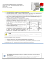
Progettato e prodotto interamente in Italia MULTIFUNZIONE LCD TRIFASE INGRESSO 5A o 100A PER MODELLI CON MINI-T.A. VERO VALORE EFFICACE MONTAGGIO GUIDA DIN GENERALITA’ Lo strumento in formato 4 DIN è adatto all’utilizzo in ambiente industriale. Semplice e molto compatto, dispone di un display alfanumerico da 2 linee di 8 caratteri ciascuna, di 6 led di ausilio e di 2 tasti per la selezione della visualizzazione e per la programmazione da tastiera. La semplicità delle operazioni di personalizzazione e la chiarezza delle indicazioni fornite a display rendono quasi superfluo l’uso del manuale di istruzioni che molto raramente è disponibile, specie sul campo. Lo strumento correttamente installato supporta correnti di ingresso massime da TA esterni/5 di 6 A max (5 nominali) o 100A con mini-T.A. (By7950). Il valore di CT programmato è da intendersi /5A o 100A con mini-T.A. (By7950). Le inserzioni delle tensioni possono essere sia dirette, max 290Vac Fase/Neutro(=230Vac+25%), che da TV (opz.). In questo caso è possibile programmare il valore di fondo scala della tensione equivalente fino a 400Vfn (=690Vff), con garanzia dei valori visualizzati fino al 25% in più (500Vfn/860Vff). In connessione diretta, il valore di VT deve coincidere con quello nominale di tensione fase/neutro, normalmente 231Vac. Viene offerta la gamma “standard” di misure che si ritiene utili avere in un ambiente di tipo industriale, di alta precisione. Le indicazioni relative alle potenze e al power factor sono fornite a 4 quadranti secondo l’allegato C della norma EN62053-23. La totalizzazione delle energie resettabili individualmente (consumata,prodotta e reattiva) può essere comoda dove si debbano pianificare interventi all’impianto e/o verifiche periodiche al funzionamento della linea, rilevare consumi di zona, stabilire centri di costo, ecc. ecc. NOTA: Lo strumento usa la semplice totalizzazione delle energie per fini diagnostici/statistici. In nessun modo lo strumento è da considerarsi sostitutivo di un contatore di energia. A seconda dei modelli, possono essere disponibili: 2 Contaore (totale non azzerabile e parziale azzerabile) 1 Soglia con uscita su relè di comando NO (500mA /1000V) completamente programmabile 1 Interfaccia RS485 optoisolata 3kV ad alta velocità, programmabile con protocollo MODBUS RTU. La presente guida ha scopo puramente informativo. Il costruttore si riserva il diritto di modificare e/o aggiornare il prodotto e la guida senza alcuna limitazione e senza obblighi di preavviso. Il costruttore non risponde di eventuali danni, diretti o indiretti, causati a persone o cose da avarie del prodotto o conseguenti la forzata sospensione dell’uso dello stesso. UG_X_06150_02_IE.docx 1/20 CARATTERISTICHE TECNICHE Alimentazione ausiliaria valore nominale U AUX potenza assorbita massima Circuiti d’entrata amperometrici per TA /5 Massima corrente applicabile (Imax) Corrente nominale misura (Inom) Campo di misura diretta Impedenza d’ingresso Sovraccarico permanente Sovraccarico termico (1 s) Campo di regolazione CT(/5) Precisione Mini-Trasformatori Amperometrici By7950 Corrente nominale primario Corrente nominale secondario Massima tensione applicabile(Vmax) Circuiti di misura voltmetrici (Strumento per inserzione diretta) Tensione nominale misura (Vnom) Campo di misura diretta Impedenza d’ingresso circuito voltmetrico Campo di regolazione VT Precisione Circuiti di misura voltmetrici (Strumento per inserzione da TV /100) (OPZIONALE) Trasformatori Voltmetrici compatibili Misura di frequenza Massima tensione applicabile(Vmax) Tensione nominale misura (Vnom) Campo di misura diretta Impedenza d’ingresso Campo di regolazione VT Precisione Tensione nominale 230V 50/60 Hz 2 VA 6A 5A 0,03...6A circa 20mΩ 110% (Inom) 200% (Inom) 5…6000A a passi di 5A 0,5%*Imax ± 2 digit 100A ~ 70 mA 300 Vfn (520 Vff) 231Vfn(400Vff) 0-300Vfn(520Vff) TRMS fino alla 20ma arm. circa 2MΩ Fase/Neutro e Fase/Fase =Vnom 0,5%*Vmax ± 2 digit 75Vfn(130Vff) 57,75 Vfn(100Vff) 0-75Vfn(130Vff) TRMS fino alla 20ma arm. circa 500KΩ Fase/Neutro e Fase/Fase 50…400Vfn(86,5…692Vff) 0,5%*Vmax ± 2 digit 100 V Rapporto di trasformazione 1...6 Campo di misura frequenza 9,50...100.00Hz Campo di funzionamento (V1) precisione 35 – 300 Vfn 0.1% ± 1 digit Misura Potenze Singole Capacità di misura per linea Precision (0.05 < I ≤ 1.0Inom) ±2,88 MW /±2,88Mvar /2,88MVA 1 % f.s ± 2 digit Misura Potenze totali Capacità di misura Precision (0.05 < I ≤ 1.0Inom) ±8,64 MW /±8,64Mvar /8,64MVA 1 % f.s ± 2 digit Misura dei fattori di potenza (tutti) Campo di misura cosφ Precisione (0.1Inom < I ≤ Inom, 0.8 Vnom < V ≤ 1,2Vnom) Totalizzazioni Energie Capacità di conteggio Periodo contabilizzazione Possibilità di azzeramento Precision (0.05 < I ≤ 1.0Inom) 99999999kWh /kvarh 15 minuti SI 2% Max Contaore di funzionamento Capacità di conteggio Periodo contabilizzazione Possibilità di azzeramento Precisione 99999:59 hhhhhh:mm 15 minuti NO 2% Max UG_X_06150_02_IE.docx -1.00…0.00…+1.00 2% fs ± 2 digit 2/20 Contaore parziale Visualizzazioni Capacità di conteggio Periodo contabilizzazione Possibilità di azzeramento Precisione Display Segnalazioni ausiliarie 99999:59 hhhhhh:mm 15 minuti SI 2% Max LCD retroilluminato, 8 caratteri x 2 linee, temp. -20°/+70° 6 Led colore ROSSO. Tipo contatto Uscita di comando a relè (solo modelli “S”) Caratteristiche del contatto Isolamento bobina-contatto Azionamento remoto via MODBUS NO 1000Vac / 0,5Aac(carico res.) / 20VA max 4,25kVac SI, solo per modelli “S485” Isolamento Interfaccia seriale RS485 (solo modelli “485”) Velocità massima di comunicazione Protocollo di comunicazione Programmabilità e comandi da remoto 3kV 115.200 bps MODBUS RTU Full-compliant / JBUS SI Funzioni speciali Protezione di accesso alla programmazione dei parametri via password a 3 cifre Black-out indicator system Specifiche dei morsetti di collegamento Corrente nominale Sezione Cavo Coppia di serraggio (torque) Dimensioni Caratteristiche meccaniche tipo di montaggio grado di protezione Condizioni ambientali Temperatura di funzionamento Campo nominale Campo estremo Temperatura d'immagazzinamento Umidità relativa Pressione atmosferica Norme di riferimento Sicurezza Precisione Compatibilità elettromagnetica (immunità) Compatibilità elettromagnetica (emissione) Gradi di protezione degli involucri (Codice IP) Modbus Specifiche del protocollo di applicazione UG_X_06150_02_IE.docx 30A 22-10AWG 4mm² 0,5Nm (4.5lb.in) Standard 4 moduli DIN guida DIN50022 Apparecchio completo IP20/ Frontale IP30 0...+45 °C -5...+55 °C -10...+70 °C 10...95 % 70...110 kPa EN 61010-1 300V CAT III EN 60688 EN 61000-6-2 EN 61000-6-4 EN 60529 V1.1b, 28.12.2006 3/20 OPERATIVITA’ NOTE E PRESCRIZIONI D’USO Mentre si accende lo strumento (cioè lo si collega all’alimentazione ausiliaria), NON TENERE PREMUTO ALCUN PULSANTE altrimenti si può accede accidentalmente ad una procedura di calibrazione che viene eseguita in fabbrica e che ,se fatta a strumento collegato all’impianto invece che agli appositi apparati di calibrazione, può comportare una possibile staratura permanente dello strumento. Per sicurezza, ATTENDERE SEMPRE LA FINE DELLA DIAGNOSTICA INIZIALE (scansione dei led) prima di agire sui tasti dello strumento. Strumenti con soglia: da quando lo strumento viene acceso, nei primi 10 secondi è inibita l’azione del relè di soglia. Durante la regolazione dei parametri, lo stato del relè rimane “congelato” fino al termine della procedura. All’accensione, per qualche istante appare la pagina info del firmware e vengono accesi tutti i led in sequenza (diagnostica iniziale). Appare poi per qualche istante la pagina con il “titolo” delle misure che compariranno a display, assieme al corrispondente led se la pagina ne prevede l’accensione. E’ possibile (successivamente alla comparsa della prima pagina di misura) iniziare ad operare con i tasti per scorrere le pagine disponibili. Lo scorrimento può avvenire “IN AVANTI” con BREVI PRESSIONI sul tasto DESTRO, oppure “INDIETRO” utilizzando il tasto sinistro. La durata prolungata della pressione sul tasto destro provoca, oltre all’avanzamento della pagina, anche l’ingresso alla programmazione dei parametri dello strumento. Quando uno dei 2 tasti viene premuto brevemente, appare invece il “titolo” della pagina di misura che verrà visualizzata. UG_X_06150_02_IE.docx 4/20 FUNZIONAMENTO Lo strumento misura e sorveglia in tempo reale le grandezze elettriche dell’impianto al quale è connesso ed è in grado di mostrarle a display su diverse pagine di misura selezionabili con brevi pressioni sui tasti, DESTRO per andare “avanti” e SINISTRO per andare “indietro”. I 6 led a destra aiutano a riconoscere le pagine di misura delle principali grandezze elettriche e vengono accesi a seconda del tipo di grandezza rappresentata al momento sul display. La prima pagina di misura da visualizzare all’accensione dello strumento è programmabile. I modelli “S” dotati di soglia consentono di impostare la grandezza che si vuole controllare, il tipo di soglia (off, di massima o di minima), il valore di soglia millesimale rispetto al fondo scala della grandezza controllata, l’applicazione del ritardo eventuale all’eccitazione o alla diseccitazione ed il tempo di ritardo stesso in decimi di secondo fino a 25,5 Sec. (0=nessun ritardo). Si faccia riferimento alla sezione “Programmazione” per i dettagli relativi ai valori di programmazione e la sezione “Funzionamento della soglia programmabile”. I modelli “485” dotati di interfaccia seriale RS485 possono essere messi in rete fra loro, dal momento che dispongono di indirizzo programmabile da 1 a 254. Per affidabilità di comunicazione, si consiglia di non collegare in rete più di 32 dispositivi per anello. Se ciò non fosse sufficiente, sono previste esecuzioni “speciali’ per supportare più di 64 dispositivi. La velocità di comunicazione è programmabile tra 9600bps e 115.200bps. Nel caso in cui in anello ci siano solo questi strumenti, consigliamo vivamente di usare la massima velocità di comunicazione. Se la velocità è troppo bassa e le domande sono molto frequenti e/o il numero di registri richiesto è elevato, si possono ottenere rallentamenti nelle interazioni con lo strumento. Tutte le misure e i parametri sono disponibili contemporaneamente su comando di lettura MODBUS RTU. Lo strumento consente anche la programmazione “on the fly” da remoto dei parametri di funzionamento via comando di scrittura MODBUS ai relativi registri che lo supportano. E’ consentito in certe condizioni anche far eseguire alcune macro-operazioni e comandi, quali ad esempio il ripristino dei parametri di fabbrica nei modelli che lo supportano, l’azzeramento dei totalizzatori o il comando diretto di accensione/spegnimento del relè di uscita per i modelli con soglia. Nota: i modelli “485” offrono misure aggiuntive via Modbus, in particolare le singole misure di fase delle potenze e dei cosφ. E’ possibile in alcuni modelli avere una pagina di segnalazione di avvenuto black-out. E’ una pagina come quelle di misura ma dal contenuto lampeggiante, che deve essere programmata come la prima da visualizzare all’accensione. Quando si agisce sui tasti per cambiare pagina di misura, viene azzerata la condizione di “avvenuto black-out”, che viene riproposta anche al termine dell’eventuale programmazione dei parametri da tastiera. Alcuni modelli dispongono di 2 contaore, uno di funzionamento totale ed uno azzerabile, utile quest’ultimo per tenere conto ad esempio del consumo medio se azzerato assieme ad uno o più totalizzatori di energia. E’ previsto su certi modelli che la modifica dei parametri di funzionamento e l’azzeramento dei contatori siano protetti da password (escludibile) a 3 cifre. Tale password non è orientata ad una protezione esaustiva, ma solo ad evitare l’accidentale accesso alla zona di programmazione e conseguente alterazione indesiderata dei parametri da parte di personale non autorizzato. Se la password viene impostata e in seguito dimenticata, non c’è un modo rapido di recuperarne il valore o di eliminarla. Sarà necessario scandire ogni combinazione, oppure rimandare il prodotto in fabbrica per la riprogrammazione. Le pagine di misura e segnalazione che appaiono premendo e rilasciando BREVEMENTE in successione il tasto DESTRO, sono descritte qui di seguito : Appare solamente quando si accende lo strumento per circa 3 secondi. Fornisce informazioni che riguardano il firmware ed i dettagli esecutivi dello strumento. Quando questa pagina è visibile, viene eseguita una veloce scansione dei led perché si possa verificarne l’efficienza. UG_X_06150_02_IE.docx 5/20 Pagina rilevamento black-out. Per poter apparire, deve essere programmata come pagina di default. Appare solo quando si accende lo strumento. Appena si sposta la visualizzazione, essa sparisce. Ricompare al termine della programmazione parametri da tastiera. Pagina INFO. Indica il modello e la versione dello strumento. La presenza del quadratino acceso (prima riga a destra) indica che le fasi di tensione sono FUORI SEQUENZA. Quando la sequenza è corretta, il quadratino è assente. Solo nei modelli “485”, l’ultimo valore in basso a destra indica il numero di nodo dello strumento in rete MODBUS. Tensioni Fase/Fase Valore di ciascuna Tensione Fase/Neutro (V) Valore di A1 e A2 (A) I valori hanno i decimali se il TA selezionato è inferiore a 1000A (/5), altrimenti sono interi Valore di A3 e della Corrente nel Neutro (A) I valori hanno i decimali se il TA selezionato è inferiore a 1000A (/5), altrimenti sono interi Potenza Attiva Totale Fattore di Potenza Trifase (Cosφ) Il segno è lo stesso della Potenza Attiva di linea. Senza indicatori “C” (capacitivo) o ” I” (induttivo), lo sfasamento è nullo. Misura della Potenza Reattiva Trifase (var) La misura è POSITIVA nei quadranti 1 e 2, NEGATIVA nei quadranti 3 e 4. Potenza Apparente Trifase Valore della Potenza Attiva Totale (W) La misura è POSITIVA per potenze consumate, NEGATIVA per potenze prodotte Fattore di Potenza Valore di Frequenza (Hz) La misura è rilevata su V1. Potenza Reattiva Frequenza Valore di ciascuna Tensione Fase/Fase (V) Tensioni Fase/Neutro DESCRIZIONE Correnti di Linea 1 e 2 AL RILASCIO Corrente di Linea 3 / Corrente nel neutro TASTO PREMUTO UG_X_06150_02_IE.docx Valore della Potenza Apparente Trifase (VA) 6/20 Totalizzazio ne Energia Attiva totale consumata Totalizzazio ne Energia Attiva totale prodotta Totalizzazio ne Energia Reattiva totale Totale Energia Reattiva (kvarh) Contaore Totale Totale Energia Attiva prodotta (kWh) Ore e minuti di funzionamento dello strumento (hhhhh:mm) Contaore Parziale Totale Energia Attiva consumata (kWh) Ore e minuti trascorsi dall’ultimo azzeramento (hhhhh:mm) Relè SOLO PER MODELLI “S” Stato del contatto del relè di uscita (On=chiuso) e sorgente della soglia. FUNZIONAMENTO DELLA SOGLIA PROGRAMMABILE I modelli “S” possono applicare una soglia di massima o di minima al valore in percentuale della grandezza scelta, rispetto al suo fondoscala previsto. Grandezza scelta (Th1 Src) W+ Fondoscala previsto (= 100,0%) CT Set * VT Set * 3 W- CT Set * VT Set * 3 Hz 100Hz 3Vf VT Set * 1,73 V12 V23 V31 3Vn VT Set * 1,73 VT Set * 1,73 VT Set * 1,73 VT Set V1 V2 V3 3A A1 A2 A3 An VT Set VT Set VT Set CT Set CT Set CT Set CT Set CT Set * 3 Descrizione Max o Min della potenza attiva istantanea consumata Max o Min della potenza attiva istantanea prodotta Max o Min della frequenza misurata su V1 Max o Min di una delle tensioni fase/fase Max o Min di V12 Max o Min di V23 Max o Min di V31 Max o Min di una delle tensioni fase/neutro Max o Min di V1 Max o Min di V2 Max o Min di V3 Max o Min di una delle correnti Max o Min di A1 Max o Min di A2 Max o Min di A3 Max o Min di An Il punto di intervento della soglia (soglia attiva) è per la condizione “maggiore di Th1 Val” se Th1 Sel = Hi; altrimenti “minore di Th1 Val” se Th1 Sel = Lo. Il punto di riposo della soglia (soglia a riposo) è per la condizione “minore o uguale a Th1 Val” se Th1 Sel = Hi; altrimenti “maggiore o uguale a Th1 Val” se Th1 Sel = Lo. UG_X_06150_02_IE.docx 7/20 La condizione di “soglia attiva” tenta di agire sulla CHIUSURA dei contatti NO del relè, la quale avviene a meno dell’eventuale ritardo Th1 Dly se Th1 DD è “Off-On”, altrimenti in modo istantaneo. La condizione di “soglia a riposo” tenta di agire sull’ APERTURA dei contatti NO del relè, la quale avviene a meno dell’eventuale ritardo Th1 Dly se Th1 DD è “On-Off”, altrimenti in modo istantaneo. Ci sono 2 casi in cui il relè di uscita NON riflette la condizione di soglia, e cioè: • • nei primi 10 secondi dall’accensione dello strumento, quando il relè viene forzato a riposo per evitare interventi indesiderati durante la stabilizzazione delle misure durante tutta la programmazione dei parametri da tastiera, dove viene mantenuto nello stato in cui si trovava al momento dell’accesso alla procedura, per evitare che la modifica parziale dei parametri possa provocarne l’indesiderato cambio di stato. Lo stato del relè è visualizzato a display sulla pagina “OUT”, assieme al titolo della grandezza di soglia selezionata in Th1 Src. La chiusura del relè determina anche il lampeggio del led corrispondente alla grandezza selezionata (dove previsto), a patto che che la pagina di misura selezionata non sia quella corrispondente al led, nel qual caso il led rimane acceso fisso. Modelli “S485” Viene data la possibilità, quando Th1 Sel = OFF (soglia spenta), di poter comandare direttamente il relè da appositi comandi MODBUS per l’apertura e la chiusura ISTANTANEA, cioè non soggetta alle impostazioni di Th1 Dly e di Th1 DD. Sulla pagina “OUT”, appare “Src=REM”(REMOTE) ad indicare la disponibilità all’accesso remoto del relè. PROGRAMMAZIONE Per poter entrare in programmazione, premere a lungo il tasto DESTRO (oltre 4 secondi consecutivi). Quando la richiesta di ingresso in programmazione viene riconosciuta, appare la prima delle “pagine” dei valori programmabili. Rilasciando il tasto, il display lampeggia (indica che ci si trova in programmazione) e le pagine di programmazione iniziano a scorrere lentamente (una ogni circa 4 sec.), mostrando il titolo e il valore di set attuale. Se non si tocca il tasto, alla fine dell’ultima pagina lo strumento si riporta alla visualizzazione normale senza nessuna modifica. Per modificare, basta premere uno dei tasti quando compare la pagina desiderata, rispettivamente: Tasto SINISTRO = DECREMENTA il valore; Tasto DESTRO = INCREMENTA il valore. A quel punto (a tasto premuto) il display rimane stabile per facilitare la visione della regolazione e il valore avanza di una unità. Per valori numericamente molto lontani, si può usare l’avanzamento veloce tenendo premuto il tasto per più di 2 secondi. Più tempo rimane premuto e più lo scorrimento accelera (4 velocità). Tutti i valori sono di tipo ‘roll’, cioè raggiunto il valore massimo permesso ripartono poi dal minimo e viceversa. Quando il valore è corretto, basta rilasciare il tasto per più di 4 secondi, così che riprende lo scorrimento delle pagine e il valore modificato viene automaticamente salvato. Seguono le pagine modificabili. Indica che si è entrati nella fase di programmazione dei parametri La richiesta di password compare solo se il parametro NewPassw è diverso da 0 (vedi più avanti). Scegliere il numero corretto e attendere la pagina successiva. In caso di mancata o errata immissione, dopo circa 4 secondi lo strumento torna alla visualizzazione normale. Premendo uno dei tasti quando è visibile questa pagina, si riportano tutti i parametri ai valori di fabbrica, eccetto per i totalizzatori che vanno azzerati singolarmente. Selezione del valore del TA (/5) in Ampère. Regolabile tra 5 e 6000 a passi di 5 oppure solo 100A con modello per mini T.A. (By7950). Default = 100 UG_X_06150_02_IE.docx 8/20 Selezione del valore del fondo scala di tensione. Se in connessione diretta, deve essere uguale al valore nominale della tensione fase/neutro di linea. In fase di regolazione, sopra compare il valore fase/fase regolabile tra 87 e 692 a passi di 1 V (Default = 400). Sotto compare il valore fase/neutro regolabile tra 50 e 400 a passi di 1 V (Default = 231) Media dei valori analogici misurati (V, A e P). Serve a stabilizzare le visualizzazioni dei valori. Più il numero è alto, più le misure sono stabili ma lente all’aggiornamento. Regolabile tra 1 e 15 a passi di 1. Default = 3 Impostazione della prima pagina di misura da far apparire all’accensione. Scorrendo con i tasti, appaiono i “titoli” delle pagine disponibili, gli stessi che compaiono premendo il tasto destro in sequenza. Regolabile tra tutte le pagine disponibili. Default = Pagina rilevamento black-out se disponibile, altrimenti Pagina INFO. Lasciando il parametro a zero, si evita che venga richiesta la password all’accesso della programmazione da tastiera. Il valore immesso qui, serve anche per la protezione password da programmazione remota. Regolabile tra 0 e 999 a passi di 1. Default = 0 (esclusa) UG_X_06150_02_IE.docx Azzeramento del Totalizzatore dell’Energia Attiva Totale consumata Tenendo premuto il tasto destro per più di 4 Secondi,il valore viene azzerato Azzeramento del Totalizzatore dell’Energia Attiva Totale prodotta Tenendo premuto il tasto destro per più di 4 Secondi, il valore viene azzerato Azzeramento del Totalizzatore dell’Energia Reattiva totale Tenendo premuto il tasto destro più di 4 Secondi, il valore viene azzerato Azzeramento del Contaore Parziale Tenendo premuto il tasto destro più di 4 Secondi, il valore viene azzerato 9/20 LE SCHERMATE CHE SEGUONO VALGONO SOLO PER I MODELLI “S” Selezione del modo di funzionamento della soglia. Regolabile tra: Hi=Soglia di Massima, Lo=Soglia di Minima e Off=Soglia spenta. Se la soglia è Off, le pagine seguenti che la riguardano NON SARANNO PRESENTI. Default = Hi (di Massima). Valore del tempo di ritardo di intervento del relè di uscita (pagina presente solo se Th1 Sel è diverso da Off) E’ espresso in Secondi. Regolabile tra 0.0 e 25.5 a passi di 0.1. Default = 0.1 Assegnazione del tempo di ritardo del relè di uscita (pagina presente solo se Th1 Sel è diverso da Off) Il tempo di ritardo è applicabile all’inizio della condizione di intervento della soglia (Off-On), oppure alla fine (On-Off). Default = Off-On (all’inizio) Assegnazione della grandezza su cui la soglia agisce (pagina presente solo se Th1 Sel è diverso da Off) Regolabile tra: W+, W-, Hz, 3Vf, V12, V23, V31, 3Vn, V1, V2, V3, 3A, A1, A2, A3,An. Default = W+ Regolazione del valore di soglia in percentuale sul fondo scala (pagina presente solo se Th1 Sel è diverso da Off) In alto appare il valore effettivo della soglia per la grandezza scelta. Regolabile tra: 0.0 e 100.0, a passi di 0.1. Default = 50.0(%) LE SCHERMATE CHE SEGUONO VALGONO SOLO PER I MODELLI “485” Assegnazione del numero di nodo di indirizzo MODBUS (quello della pagina “INFO”). Regolabile tra 1 e 255. Default = 1 Impostazione della velocità della porta seriale RS485 (bps). Regolabile tra 0 e 4 (0=9600, 1=19200, 2=38400, 3=57600, 4=115200) Default = 4 UG_X_06150_02_IE.docx 10/20 Desisgned and manufactured entirely in Italy LCD THREEPHASE MULTIFUNCTION METER INPUT 5A or 100A FOR MODELS WITH MINI-C.T. TRUE RMS DIN RAIL MOUNTING GENERAL DESCRIPTION The 4 DIN instrument is suited for use in an industrial environment Simple and extremely compact, it features an alphanumerical display with 2 eight-character lines, 6 auxiliary leds and 2 buttons for display selection and keyboard programming. The device is extremely user-friendly and information is presented clearly on the display. It is unlikely you will need to consult instruction manual which is not generally kept readily available at the site. When properly installed, the instrument can accept full intake flow from external CT at a voltage of 5 to 6 A max (5 nominal) or 100A with mini C.T. (By7950). The programmed voltage is /5 A or 100A with mini-C.T. (By7950) Voltage can be direct, max 290Vac Phase/Neutral (=230Vac+25%), or from VT (optional). In this case it is possible to program the full scale value for equivalent voltage at up to 400Vpn (=690Vcc), with guarantee of the displayed values up to 25% more (500Vpn/860Vpp). For direct connection, the VT must be the same as the rated phase/neutral voltage, normally 231Vac. There is a “standard” range of measurements for a high precision industrial environment. Power and power factor data are showed on 4 dials according to annex C in standard EN62053-23. The individually resettable energies (imported, exported and reactive) can be easily calculated when you need to service the system and/or test line operation, determine zone consumption values, establish cost centres, etc. NOTE: The instrument uses simple energy totalizing methods for purposes of diagnostics and statistics. The instrument cannot replace an energy counter. According to model the following are provided: 2 counters (total counter is non-resettable and partial counter is resettable) 1 threshold with output on “NO” control relay (500mA/1000V), fully programmable. 1 x RS485 3kV optoinsulated and high speed interface, programmable by MODBUS RTU protocol. The operating instructions, measurements and technical specifications are given below. This guide is for information only. The manufacturer reserves the right to modify and / or update the product manual without reservation and without prior notice. The manufacturer, including his international representatives or agents, do not accept any liability for any incidental damage, directly or indirectly, to people or properties through the use of his products. UG_X_06150_02_IE.docx 11/20 SPECIFICATIONS Auxiliary power supply U AUX nominal value max rated consumption Amp measuring circuits for CT /5 Max applicable current (Imax) Rated current measurement (Inom) Direct measurement range Input impedance of current circuit Permanent overload Thermal overload (1 s) Current transformer (Ct) control range (/5) Precision By7950 mini-amp transformers Rated current of the primary circuit Rated current of the secondary circuit Max applicable voltage (Vmax) Voltmeter measuring circuits (instrument for direct insertion) Rated voltage measurement (Vnom) Direct measuring field Input impedance of voltage circuit Vt control range Precision Voltmeter measuring circuits (instrument for insertion from VT /100) Compatible voltmeter transformers Frequency measurement Maximum applicable voltage (Vmax) Rated voltage measurement (Vnom) Direct measuring range Input impedance Control range VT Precision Rated voltage Transformer ratio Frequency measuring range Operating range (V1) precision 230V 50/60 Hz 2 VA 6A 5A 0,03...6A about 20mΩ 110% (Inom) 200% (Inom) 5…6000A, 5A step 0.5%*Imax ± 2 digit 100A ~ 70 mA 300 Vpn (520 Vpp) 231Vpn(400Vpp) 0-300Vpn(520Vpp) TRMS up to 20th harm. circa 2MΩ Phase/Neutral and Phase/Phase =Vnom 0.5%*Vmax ± 2 digit 75Vpn(130Vpp) 57,75 Vpn(100Vpp) 0-75Vpn(130Vpp) TRMS up to 20th harm. about 500KΩ Phase/Neutral and Phase/Phase 50…400Vpn(86,5…692Vpp) 0,5%*Vmax ± 2 digit 100 V 1...6 9,50...100.00Hz 35 – 300 Vpn 0.1% ± 1 digit Single power measurement Measurement limit per line Precision (0.05 < I ≤ 1.0Inom) ±2.88 MW /±2.88Mvar /2.88MVA 1 % e.s ± 2 digit Total power measurements Measuring limit Precision (0.05 < I ≤ 1.0Inom) ±8.64 MW /±8.64Mvar /8.64MVA 1 % e.s ± 2 digit Power factor measurement (all) Measuring range cosφ Precision (0.1Inom < I ≤ Inom, 0.8 Vnom < V ≤ 1,2Vnom) Energy totalizing Counting limit Counting period Resettable Precision (0.05 < I ≤ 1.0Inom) 99999999kWh /kvarh 15 minutes YES 2% Max Operating counter Counting limit Counting period Resettable Precision (0.05 < I ≤ 1.0Inom) 99999:59 hhhhhh:mm 15 minutes NO 2% Max UG_X_06150_02_IE.docx -1.00…0.00…+1.00 2% e.s ± 2 digit 12/20 Partial counter Screens Counting limit Counting period Resettable Precision Display Auxiliary signals Type of contact Relay control output (only “S” models) Contact specifications Reel-contact insulation Remote operation via MODBUS Insulation RS485 serial interface (only “485” models) Max communication baudrate Communication protocol Programmability and remote controls Special functions 3-digit password for the programming of the settings Black-out indicator system Terminal specifications Rated current Cable cross-section Torque Dimensions Mechanical properties Type of assembly Degree of protection Environmental conditions Operating temperature Nominal range Extreme range Storage temperature Relative humidity Atmospheric pressure Standards Safety Precision Electromagnetic compatibility (immunity) Electromagnetic compatibility (emission) Cover protection (IP code) Modbus Protocol specifications UG_X_06150_02_IE.docx 99999:59 hhhhhh:mm 15 minutes YES 2% Max Backlighted LCD, 8 characters x 2 lines, temp. -20°/+70° 6 RED leds NO 1000Vac / 0.5Aac (res. load) / 20VA max 4.25kVac YES, only for “S485” models 3kV 115,200 bps MODBUS RTU Full-compliant / JBUS YES 30A 22-10AWG 4mm² 0.5Nm (4.5lb.in) Standard 4 moduli DIN guida DIN50022 Apparecchio completo IP20/ Frontale IP30 0...+45 °C -5...+55 °C -10...+70 °C 10...95 % 70...110 kPa EN 61010-1 300V CAT III EN 60688 EN 61000-6-2 EN 61000-6-4 EN 60529 V1.1b, 28.12.2006 13/20 OPERATION NOTES AND OPERATING INSTRUCTIONS DO NOT PRESS ANY OF THE KEYS while switching on the instrument (i.e. when connecting it to the auxiliary power supply). Otherwise you may accidentally start the calibration procedure normally carried out at the factory which, if the instrument is connected to the system rather than to the respective calibration devices, could cause the instrument to be permanently uncalibrated. For safety, ALWAYS WAIT FOR END OF THE INITIAL DIAGNOSTICS (scanning of the leds) before pressing any of the keys. “S” instruments with threshold: The threshold relay is blocked for the first ten seconds after the instrument is switched on. The relay is “frozen” until the ending of the setting procedure. When you start up the device, the firmware information page appears for few seconds and all the leds switch on in order (initial diagnostics). You will then see, for few seconds, the page with the “title” of the measurements that will appear on the display, and the respective led will switch on if the page requires it to do so. When the first measurement page appears, you can press the buttons to scroll through the available pages. You can scroll FORWARDS by QUICKLY PRESSING the RIGHT-HAND button, or BACKWARDS by pressing the LEFT-HAND button. Pressing and holding the right-hand button will take you to the next page as well as allow you to enter the programming mode of the instrument. Pressing one of the 2 buttons quickly the “title” of the measurement page to be displayed will appear. UG_X_06150_02_IE.docx 14/20 GENERAL OPERATION The instrument calculates and monitors the electrical measurements of the plant to which it is connected. It displays the information on different pages on the display which can be selected by quickly pressing one of the buttons. The RIGHT button is for “next page” and the LEFT button is for “previous page”. The 6 leds on the right help to indicate the main electrical measurement page and light on according to the type of measurement shown on the display at the time. The first measurement page that appears upon start-up can be programmed. The “S” models with threshold allow you to configure the measurement to be controlled, the type of threshold (off, maximum or minimum), the millesimal threshold value in relation to the full scale of the controlled measurement, time delay upon activation or deactivation, if applicable, and the time delay in tenths of a second up to 25.5 seconds (0=no delay). Refer to the “Programming” section for details on programming values and the “Operation of the programmable threshold” section. The “485” models with RS485 interface can communicate via a network when they are assigned a programmable address between 1 and 254. You are advised not to put more than 32 devices on a network so as to ensure reliable communication. If this is not adequate, there are “special” versions able to support more than 64 devices. Communication speed can be set at between 9600bps and 115,200bps. You are advised to set the communication speed at maximum if only these devices are used. If the speed is set too low and there are frequent requests and/or there is a high number of required records, interactions with the instrument may also slow down. All measurements and parameters can be viewed on the MODBUS RTU interface. The instrument also enables “on the fly” remote programming of the work settings via the MODBUS interface with the respective records that support it. In certain situations you are also allowed to carry out some macro-operations and controls, such as restoring the factory settings of models that enable this, resetting of the counters or direct switching on and off the output relay for models with threshold. Note: the “485” models offer additional measurements via Modbus, in particular single phase measurements of the powers and cosφ values. Some models feature a blackout indication page. It is like the measurement page but with flashing content which has to be programmed like the initial page shown on start-up. When you press the keys to change the measurement page, the “blackout” condition is reset. This page is proposed again after any programming of the settings on the keyboard. Some models feature 2 counters – one for total operation and another that can be reset. The latter allows you to check the average consumption if reset together with one or more energy counter. Some models require a 3-digit password (that can be excluded) to change the work settings and reset the counters. This password is not intended to guarantee full protection but to prevent accidental access to the programming area and ensure the settings are not changed by unauthorized people. There is no easy way to recover or cancel a password that has been configured and then forgotten. You will have to try all the combinations or return the product to the factory for reprogramming. The measurement and indication pages that can be accessed by pressing and QUICKLY releasing the RIGHT-HAND button are as follows: It appears only for about 3 seconds when the instrument is switched on. It provides information on the instrument’s firmware and operating details. When this page is displayed, the leds flash quickly to indicate they are working properly. Black-out page For this to appear, it has to be configured as the default page. Appears only when the instrument is switched on. It disappears as soon as the display is moved. It reappears after the settings are configured using the keypad. UG_X_06150_02_IE.docx 15/20 INFO page. It indicates the instrument model and version. The lit-up square (first line on the right) indicates the voltage phases are OUT OF SEQUENCE. The square does not appear when the sequence is correct. Only in the case of the “485” models the last value at the bottom on the right indicates the node number of the instrument on the MODBUS network. Phase-tophase voltages Value of each phase-to-neutral voltage (V) Value of A1 and A2 (A) The values have decimal separator if the selected CT is less than 1000A (/5), otherwise they are integer. Value of A3 and Neutral Current (A) The values have decimal separator if the selected CT is less than 1000A (/5), otherwise they are integer. Three-phase power factor (Cosφ) The sign is the same as the respective active line power. The phase displacement is void without the indicators “C” (capacitive) or “I” (inductive). Three-phase apparent power Value of Three-phase Apparent Power (VA) Total active energy (import) Measurement of Three-phase Reactive Power (var) The measurement is POSITIVE for dials 1 and 2, NEGATIVE for dials 3 and 4. Total Active Energy imported (kWh) Total active energy (export) Reactive power Total active power (W) The measurement is POSITIVE for consumed power, NEGATIVE for power produced. Power factor Frequency (Hz) This is measured by V1. Total active power Frequency Value of each phase-to-phase voltage (V) Phase-toneutral voltages DESCRIPTION Currents of Lines 1 and 2 WHEN RELEASE Current of Line 3 / Current in neutral PRESSED BUTTON Total active energy exported (kWh) UG_X_06150_02_IE.docx 16/20 Total reactive energy Total counter The instrument’s operating time in hours and minutes (hhhhh:mm) Partial counter Total reactive energy (kvarh) Time since last reset in hours and minutes (hhhhh:mm) Relay ONLY FOR “S” MODELS Status of the output relay contact (On=closed) and source of the threshold OPERATION OF THE PROGRAMMABLE THRESHOLD The “S” models allow you to apply a maximum or minimum threshold as a percentage of the required size, in relation to its intended full scale. Selected quantity (Th1 Src) W+ Full scale (= 100,0%) CT Set * VT Set * 3 W- CT Set * VT Set * 3 Hz 100Hz 3Vf VT Set * 1,73 V12 V23 V31 3Vn VT Set * 1,73 VT Set * 1,73 VT Set * 1,73 VT Set V1 V2 V3 3A A1 A2 A3 An VT Set VT Set VT Set CT Set CT Set CT Set CT Set CT Set * 3 Description Max or Min of instantly consumed active power Max or Min of instantly produced active power Max or Min of frequency measured on V1 Max or Min of a phase-to-phase voltage Max or Min of V12 Max or Min of V23 Max or Min of V31 Max or Min of a phase-to-neutral voltage Max or Min of V1 Max or Min of V2 Max or Min of V3 Max or Min of a current Max or Min of A1 Max or Min of A2 Max or Min of A3 Max or Min of An The threshold activation (threshold active) point is the condition “more than Th1 Val” if Th1 Sel = Hi; otherwise “less than Th1 Val” if Th1 Sel = Lo. The threshold’s quiescent operating (threshold inactive) point is the condition “less than or equal to Th1 Val” if Th1 Sel=Hi; otherwise “more than or equal to Th1 Val” if Th1 Sel=Lo. The “active threshold” condition tries to CLOSE the relay’s “NO” contacts and this occurs instantly unless there is the delay Th1 Dly if Th1 DD is “Off-On”. The “inactive threshold” condition tries to OPEN the relay’s “NO” contacts and this occurs instantly unless there is the delay Th1 Dly if Th1 DD is “On-Off”. There are 2 cases whereby the output relay does NOT mirror the threshold condition. These are as follows: During the first 10 seconds from starting up the instrument, when the relay is kept inactive to avoid unwanted operations while the measurements are stabilized when the settings are being programmed on the keypad, it is kept at the same status at the time of starting the procedure, to prevent partial modification of the settings from causing unwanted changes to its status. UG_X_06150_02_IE.docx 17/20 Relay status is shown on the display at page “OUT”, together with the title of the threshold quantity selected in Th1 Src. Closing of the relay also determines flashing of the associated led with the selected quantity (when applicable), providing the selected measurement page is not the one associated with the led, in which case the led light remains steady. “S485” Models When Th1 Sel=OFF (threshold OFF), there is the option of controlling the relay directly by means of MODBUS commands to open and close INSTANTLY, regardless of the Th1 Dly and Th1 DD settings. “Src=REM”(REMOTE) appears on the OUT page to indicate remote access of the relay. PROGRAMMING To enter programming mode, press and hold the RIGHT-HAND button (for 4 seconds or more). The first page which appears when you are granted access to the programming mode is the one of programmable values. Releasing the button will make the display flashes (to indicate you are in programming mode) and the pages begin to scroll through slowly (one every 4 seconds), indicating the title and value of the present set-point. If you do not touch the button when you get the last page, normal operation is restored without saving any changes. To make a change, simply press one of the buttons when the required page appears, respectively: LEFT-HAND button = DECREASES the value; RIGHT-HAND button = INCREASES the value. At that point (after pressing the button) the display remains steady so you can check the modification and the value changes by one unit. If you have to modify a value quite considerably, you can press and hold the button for more than 2 seconds to speed up the process. The longer you hold down the button, the faster you can scroll through the numbers (4 speeds). They are all “roll” values so when you get to the maximum permitted value you restarted from the minimum value, and vice versa. When you have set the value as required, release the button and wait for over 4 seconds. The pages then continue scrolling and the modification is automatically saved. Modifiable pages then follow. indicates you have entered the setting configuration phase. A password is only requested if NewPassw is set at a value different from 0 (see below). Select the correct sequence and wait for the next page. In the case of a missing or incorrect entry, the instrument returns to normal operation after about 4 seconds. By pressing a key when this page is shown, all value parameters return equal to the factory programming, except totalizer which will be resetting one by one. Select the CT value (/5) in Ampères. Range: from 5 to 6000 in steps of 5 or solo 100A for the model with mini C.T. (By7950). Default = 100 Select the voltage full-scale value. In direct connection case, it must be settable amoung 87 and 692 at steps of 1 V (default = 400) equal to the rated value of the phase-to-neutral line voltage. UG_X_06150_02_IE.docx 18/20 During configuration, above is the phase-to-phase value settable amoung 87 and 692, at steps of 1 V (Default = 400). Below is the phase-to-neutral value settable amoung 50 and 400 at steps of 1 V (Default = 231) Average of the analog values measured (V, A and P). To stabilize the displayed values. The greater is the number, the more stable are the measurements – although they will be slow to update. Settable amoung 1 and 15 at steps of 1. Default = 3 Configuration of the first measurement page to be viewed at the start-up. Using the buttons to scroll through displays, the “titles” of the available pages are shown – the same ones that appear when you press the right-hand button in sequence. Settable on all the available pages. Default = Blackout detection page, if available, otherwise the INFO page. The value 0 disables password protection for programming with the keypad. The same applies for password protection for programming by remote control. Settable amoung 0 and 999 at steps of 1. Default = 0 (disabled) UG_X_06150_02_IE.docx Reset of Total Active Energy (exported) counter Pressing and holding the right-hand button for more than 4 seconds resets the value. Reset of the Total Active Energy (imported) counter Pressing and holding the right-hand button for more than 4 seconds resets the value. Reset the Total Reactive Energy counter Pressing and holding the right-hand button for more than 4 seconds resets the value. Reset the Partial hour counter Pressing and holding the right-hand button for more than 4 seconds resets the value 19/20 THE WINDOWS BELOW APPLY ONLY TO THE “S” MODELS Threshold operation mode selection. Settable amoung: Hi=High threshold, Lo=Low threshold and Off=threshold disabled. If the threshold is OFF, you will not view the following pages. Default = Hi (high threshold). Delay time for activation of the output relay (page displayed only if Th1 Sel is not Off) In seconds. Settable amoung 0.0 and 25.5 in steps of 0.1. Default = 0.1 Assigning the delay time for activating the threshold (page displayed only if Th1 Sel is not Off) The delay time is applicable from the start of threshold activation (Off-On) or at the end (On-Off). Default = Off-On (at the start) Assigning the quantity for activating the threshold (page displayed only if Th1 Sel is not Off) Settable at: W+, W-, Hz, 3Vf, V12, V23, V31, 3Vn, V1, V2, V3, 3A, A1, A2, A3,An. Default = W+ Regulating the threshold value as a percentage of the full scale (page displayed only if Th1 Sel is not Off) At the top is the effective value of the threshold for the selected quantity. Settable ampung: 0.0 and 100.0, in steps of 0.1. Default = 50.0(%) THE WINDOWS BELOW APPLY ONLY TO THE “485” MODELS Assigning the MODBUS address node number (of the “INFO” page). Settable amoung 1 and 255. Default = 1 Configuring the speed of the RS485 serial port (bps). Settable amoung 0 and 4 (0=9600, 1=19200, 2=38400, 3=57600, 4=115200) Default = 4 UG_X_06150_02_IE.docx 20/20