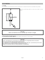
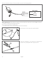
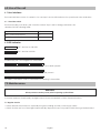
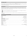
1
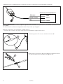
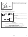
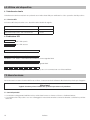
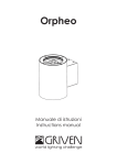
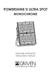
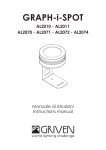
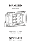
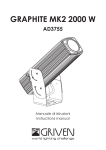
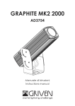
Wireless DMX Receiver
AL3360
Manuale di istruzioni
Instructions manual
INDICE
1.0 Introduzione...................................................................................................................................4
1.1 Informazioni di sicurezza.........................................................................................................................................4
1.1.1 Protezione da scariche elettriche ..................................................................................................................4
1.1.2 Installazione .....................................................................................................................................................4
1.1.3 Protezione dagli incendi .................................................................................................................................4
1.1.4 Protezione da solidi e liquidi...........................................................................................................................4
1.2 Condizioni di garanzia ............................................................................................................................................4
1.3 Normative .................................................................................................................................................................4
2.0 Dimensioni .....................................................................................................................................5
3.0 Avviamento rapido.......................................................................................................................5
4.0 Imballo e trasporto .......................................................................................................................6
4.1 Imballo......................................................................................................................................................................6
4.2 Trasporto ...................................................................................................................................................................6
5.0 Installazione ..................................................................................................................................7
5.1 Fissaggio ...................................................................................................................................................................7
5.2 Collegamento della tensione di alimentazione ...................................................................................................7
5.3 Collegamento del segnale DMX ...........................................................................................................................9
6.0 Utilizzo del dispositivo.................................................................................................................10
6.1 Interfaccia utente ..................................................................................................................................................10
6.1.2 Funzionalità ....................................................................................................................................................10
6.2 Indicatore LED ........................................................................................................................................................10
7.0 Manutenzione .............................................................................................................................10
7.1 Controlli periodici ..................................................................................................................................................10
8.0 Parti di ricambio..........................................................................................................................11
9.0 Smaltimento dell’apparecchiatura...........................................................................................11
10.0 Specifiche tecniche .................................................................................................................11
INDEX
1.0 Introduction .................................................................................................................................12
1.1 Safety information..................................................................................................................................................12
1.1.1 Protecting against electric shock ................................................................................................................12
1.1.2 Installation ......................................................................................................................................................12
1.1.3 Protection against burns and fire .................................................................................................................12
1.1.4 Weather protection........................................................................................................................................12
1.2 Warranty conditions...............................................................................................................................................12
1.3 Compliance ...........................................................................................................................................................12
2.0 Size ...............................................................................................................................................13
3.0 Quick turn on...............................................................................................................................13
4.0 Packaging and transport ...........................................................................................................14
4.1 Packaging ..............................................................................................................................................................14
4.2 Transport .................................................................................................................................................................14
5.0 Installation ...................................................................................................................................15
5.1 Fixing .......................................................................................................................................................................15
5.2 Connection to mains power .................................................................................................................................15
5.3 Connection to DMX signal ....................................................................................................................................17
6.0 Use of the unit..............................................................................................................................18
6.1 User Interface .........................................................................................................................................................18
6.1.1 Function switch ..............................................................................................................................................18
6.2 LED Indicator ..........................................................................................................................................................18
7.0 Maintenance...............................................................................................................................18
7.1 Regular Checks......................................................................................................................................................18
8.0 Spare parts ..................................................................................................................................19
9.0 Disposal........................................................................................................................................19
10.0 Technical specifications ..........................................................................................................19
1.0 Introduzione
1.1 Informazioni di sicurezza
Attenzione!
Questo prodotto è adatto solo ad un uso professionale, non ad un uso domestico.
1.1.1 Protezione da scariche elettriche
• Togliere l’alimentazione prima di effettuare qualsiasi operazione all’interno dell’apparecchiatura.
• Non utilizzate l’apparecchiatura in assenza di una connessione di terra.
• Prima di connettere l’apparecchio alla rete elettrica, verificate la compatibilità di tensione e frequenza.
• Non maneggiate il prodotto con mani bagnate o in presenza di acqua.
• Controllate periodicamente che il cavo di alimentazione non sia schiacciato o danneggiato.
• Rivolgersi ad un tecnico qualificato per qualsiasi operazione di manutenzione ordinaria non descritta nel presente manuale.
1.1.2 Installazione
• Fissate l’apparecchiatura con viti, ganci o altri supporti in grado di sostenerne il peso.
• Se fissate l’apparecchiatura ad una struttura sospesa sopra il livello del terreno, verificare che la struttura possa
sostenere almeno dieci volte il peso di tutti i dispositivi installati.
• Le operazioni di installazione dell’apparecchiatura devono essere eseguite da personale competente e qualificato.
1.1.3 Protezione dagli incendi
•
Idoneo ad essere installato su superfici normalmente infiammabili.
• Non installate l’apparecchio in locali in cui la temperatura ambiente supera i 40° (104°F).
1.1.4 Protezione da solidi e liquidi
Il dispositivo rientra nella classificazione di apparecchio ordinario, con grado di protezione IP65
1.2 Condizioni di garanzia
• Ogni articolo prodotto dalla ditta italiana GRIVEN Srl è stato assemblato e costruito in conformità alle vigenti
norme e normative CE.
• Ogni singolo prodotto e componente sono stati testati prima dell’assemblaggio finale ed ogni prodotto è sottoposto ad un controllo di qualità interno prima di essere spedito.
• GRIVEN Srl garantisce la buona qualità e realizzazione dei propri prodotti e si impegna a riparare o sostituire a
propria discrezione, nel più breve tempo possibile, qualsiasi parte che – durante il periodo di garanzia – mostri
difetti di costruzione, assemblaggio o materiale.
• La garanzia è valida per la durata di 12 (dodici) mesi dalla data di consegna del prodotto.
• GRIVEN Srl non risponde dei danni riportati dal prodotto durante il trasporto oppure derivanti da un utilizzo improprio o da un’inappropriata manutenzione dello stesso.
• Sono escluse dalla presente garanzia tutte le parti considerate di consumo o soggette a normale logorio.
• Il cliente dovrà restituire le parti difettose alla GRIVEN Srl a suo carico e rischio.
• Le parti riparate o sostituire verranno spedite dalla GRIVEN ex-factory.
• Per ogni controversia sarà competente il foro di Mantova (Italia) in conformità alla relativa giurisdizione italiana.
1.3 Normative
• L’apparecchio soddisfa i requisiti della normativa EN60598-1 EN60598-2-17.
• L’apparecchio soddisfa i requisiti della direttiva 2002/95/CE (RoHS).
4
Italiano
2.0 Dimensioni
67mm
2,64in
42,1mm
1,66in
122mm
4,80in
239mm
9,41in
3.0 Avviamento rapido
In questo capitolo troverete elencate brevemente le operazioni necessarie per utilizzare immediatamente il dispositivo. Queste istruzioni sono indispensabili per la connessione e l’alimentazione dell’apparecchio, ma non descrivono in modo completo le sue funzionalità. Vi invitiamo quindi a leggere anche gli altri capitoli di questo
manuale, in modo da apprendere tutte le informazioni relative al dispositivo.
A. Aprite l’imballo e verificate il contenuto, come descritto nel capitolo 4.0 Imballo e trasporto.
B. Installate la scatola come descritto nel capitolo 5.0 Installazione.
C. Collegate il segnale DMX mediante il connettore “1”.
Per mantenere il grado di protezione IP67, utilizzate i connettori
XLR3 opzionali cod. AL1491 e AL1493.
1
Italiano
5
D. Alimentate il dispositivo utilizzando il cavo di alimentazione “2”
2
4.0 Imballo e trasporto
4.1 Imballo
Controllate attentamente il contenuto del cartone e, in caso di danni al prodotto, contattate il Vs. trasportatore.
Nell’imballaggio sono contenuti i seguenti prodotti:
n° 1 Wireless DMX Receiver AL3360
n° 1 manuale di istruzioni
n° 1 kit di connessione
Attenzione!
• La responsabilità di Griven S.r.l. cessa all’atto della consegna del materiale al vettore: reclami per eventuali
danni dovuti al trasporto dovranno essere indirizzati direttamente al corriere.
• Si accettano reclami entro e non oltre i 7 giorni dal ricevimento merce.
• Eventuali resi di materiale dovranno essere autorizzati da Griven S.r.l. ed inviati completi della documentazione
fiscale necessaria.
4.2 Trasporto
Si raccomanda di trasportare l’apparecchiatura con estrema attenzione, utilizzando il suo imballo originale per
evitare di danneggiare il prodotto.
6
Italiano
5.0 Installazione
5.1 Fissaggio
Il dispositivo può essere utilizzata sia appoggiato a terra che fissato ad una struttura e può funzionare in qualsiasi
posizione.
133mm
5,24in
Utilizzare i due fori Ø4.5 (0.18”) sulla scatola per fissare l’apparecchiatura.
24mm
0,94in
Attenzione!
Verificate che la struttura possa sostenere almeno 10 volte il peso dell’apparecchiatura.
5.2 Collegamento della tensione di alimentazione
Il dispositivo può funzionare con tensioni da 90 a 250Vac e con frequenze di 50 e 60Hz.
Attenzione!
• Prima di collegare l’apparecchio assicuratevi che la fornitura elettrica corrisponda a quelle ammesse.
• Non installate mai l’apparecchio senza la connessione di terra.
• E’ consigliato l’uso di un interruttore magnetotermico/differenziale sulla linea di alimentazione, come prescritto
dalle norme in vigore.
• Non alimentate il proiettore attraverso unità di potenza dimmer.
• Le operazioni di cablaggio e collegamento devono essere eseguite da personale qualificato.
Italiano
7
Collegate il cavo di alimentazione posteriore secondo lo schema riportato nella figura seguente.
Tensione di alimentazione
Marrone
Giallo Verde
Blu
Fase
Terra
Neutro
Wireless DMX Receiver è fornito di giunti e guaina termoretraibile che permettono di ottenere connessioni con
grado IP67.
Per effettuare la connessione seguite le istruzioni riportate qui di seguito.
A. Aprite il sacchetto con etichetta “POWER SUPPLY”.
Troverete al suo interno un pezzo di guaina termoretraibile e 4 giunti testa-testa.
B. Infilate la guaina “3” sul cavo di alimentazione “4”
4
3
C. Effettuate la connessione alla rete utilizzando i giunti testa-testa
“5”, pressandoli con uno strumento adeguato “6”.
6
5
8
Italiano
D. Scaldate la guaina utilizzando un riscaldatore per termoretraibili “7” fino al completo restringimento.
La connessione così ottenuta ha in grado di protezione IP67.
7
5.3 Collegamento del segnale DMX
Il dispositivo è dotato di connettore XLR3 IP67 output DMX.
Pin 1: GND
Pin 2: DATAPin 3: DATA+
Dimensioni cavo DMX
Terminale
di linea IP67
(R=120 ƺ
non inclusa!)
ø 6 MIN
ø 8 MAX
Il segnale DMX deve essere collegato utilizzando un cavo
schermato progettato per congegni RS-485, con sezione
minima di 0.35mm².
Il cavo di segnale deve essere collegato rispettando la
seguente tabella:
pin 1 = GND
pin 2 = data pin 3 = data +
In caso di apparecchi DMX con connettori a 5 poli i pin 4
e 5 non devono essere connessi.
Attenzione!
La schermatura ed i conduttori non devono fare alcun tipo di contatto tra loro
o con la custodia metallica dei connettori.
Il pin numero 1 e la custodia non devono essere collegate alla massa elettrica dell’apparecchio.
Nell’ultima apparecchiatura della linea DMX inserite una spina di terminazione
con resistenza da 120 Ω collegata ai pin 2 e 3.
Per collegare il segnale DMX o il terminale di linea, mantenendo il grado di protezione IP67,
utilizzate ESCLUSIVAMENTE i connettori XLR3 opzionali cod. AL1491 e AL1493.
Italiano
9
6.0 Utilizzo del dispositivo
6.1 Interfaccia utente
L’interfaccia utente consiste in un pulsante e un indicatore LED per verificare lo stato operativo del dispositivo.
6.1.2 Funzionalità
Le funzionalità del pulsante sono descritte nella tabella di seguito.
Funzione del Wireless DMX receiver
Inattivo / Normale funzionamento
Disconnetti dispositivo dal trasmettitore
6.2 Indicatore LED
Pressione
No
> 3 sec
“Off” LED spento
“On” LED acceso
Off = Nessun trasmettitore connesso
ON 900ms / Off 100ms = Trasmettitore connesso, senza segnale DMX
Continuously On = Trasmettitore connesso con segnale DMX
On 100ms / Off 100ms = Segnale del trasmettitore perso o in connessione con il trasmettitore
7.0 Manutenzione
Per assicurare la massima funzionalità e resa ottica. si raccomanda di attenersi alle istruzioni riportate qui di seguito.
Attenzione!
Togliete tensione prima di effettuare qualsiasi operazione sul proiettore.
7.1 Controlli periodici
• Controllate i collegamenti elettrici ed in particolare la messa a terra ed il cavo di alimentazione.
• Controllate che il dispositivo non sia danneggiato meccanicamente ed eventualmente sostituite le parti deteriorate.
10
Italiano
8.0 Parti di ricambio
Tutti i componenti dell’apparecchiatura sono disponibili come parti di ricambio presso i rivenditori Griven. Le viste
esplose, lo schema elettrico, il diagramma elettronico e la brochure promozionale sono disponibili su richiesta.
Per facilitare il lavoro del centro di assistenza ricordate di specificare il numero di serie ed il modello di transformer box di cui avete richiesto i ricambi.
9.0 Smaltimento dell’apparecchiatura
La direttiva Europea 2002/96/CE sui rifiuti di apparecchiature elettroniche (RAEE), prevede che gli apparecchi
illuminanti non debbano essere smaltiti nel normale flusso dei rifiuti solidi urbani. Gli apparecchi dismessi debbono
essere raccolti separatamente per ottimizzare il tasso di recupero e riciclaggio dei materiali che li compongono
ed impedire potenziali danni per la salute e l’ambiente.
Il simbolo del cestino barrato è riportato su tutti i prodotti per ricordare gli obblighi di raccolta separata.
Per ulteriori informazioni sulla corretta dismissione delle apparecchiature, i detentori potranno rivolgersi al servizio
pubblico preposto o ai rivenditori.
10.0 Specifiche tecniche
Caratteristiche meccaniche
Altezza . . . . . . . . . . . . . . . . . . . . . . . . . . . . . . . . . . . . . . . . . . . . . . . . . . . . . . . . . . . . . . . . . . . . . . . . . . . . . .239mm (9,41”)
Larghezza . . . . . . . . . . . . . . . . . . . . . . . . . . . . . . . . . . . . . . . . . . . . . . . . . . . . . . . . . . . . . . . . . . . . . . . . . . . .67mm (2.64”)
Profondità . . . . . . . . . . . . . . . . . . . . . . . . . . . . . . . . . . . . . . . . . . . . . . . . . . . . . . . . . . . . . . . . . . . . . . . . . . .42,1mm (1,66”)
Peso . . . . . . . . . . . . . . . . . . . . . . . . . . . . . . . . . . . . . . . . . . . . . . . . . . . . . . . . . . . . . . . . . . . . . . . . . . . . . .0.62 Kg (1.36Lbs)
Caratteristiche termiche
Massima temperatura ambiente . . . . . . . . . . . . . . . . . . . . . . . . . . . . . . . . . . . . . . . . . . . . . . . . . . . . . . . . . . .35°C (95°F)
Massima temperatura superficiale . . . . . . . . . . . . . . . . . . . . . . . . . . . . . . . . . . . . . . . . . . . . . . . . . . . . . <60°C ( <140°F)
Caratteristiche elettriche
Tensione di alimentazione . . . . . . . . . . . . . . . . . . . . . . . . . . . . . . . . . . . . . . . . . . . . . . . . . . . . . . . . .90 - 250Vac 50/60Hz
Potenza massima . . . . . . . . . . . . . . . . . . . . . . . . . . . . . . . . . . . . . . . . . . . . . . . . . . . . . . . . . . . . . . . . . . . . . . . . . . . . . . 1W
Protezione termica . . . . . . . . . . . . . . . . . . . . . . . . . . . . . . . . . . . . . . . . . . . . . . . . . . . . . . . . . . . . . . . . . . . . . . Elettronica
Controllo
Protocollo . . . . . . . . . . . . . . . . . . . . . . . . . . . . . . . . . . . . . . . . . . . . . . . . . . . . . . . . . . . . . . . . . . . . . . . . . . . USITT DMX-512
Canali trasmessi . . . . . . . . . . . . . . . . . . . . . . . . . . . . . . . . . . . . . . . . . . . . . . . . . . . . . . . . . . . . . . . . . . . . . . . . . . . . . . . 512
Costruzione
Corpo . . . . . . . . . . . . . . . . . . . . . . . . . . . . . . . . . . . . . . . . . . . . . . . . . . . . . . . . . . . . . . . . . . . . . . . . . . . . . . . . . . . Alluminio
Trattamento . . . . . . . . . . . . . . . . . . . . . . . . . . . . . . . . . . . . . . . . . . . . . . . . . . . . . . . . . . . . . . . . . . . . . Vernice antigraffio
Fattore di protezione . . . . . . . . . . . . . . . . . . . . . . . . . . . . . . . . . . . . . . . . . . . . . . . . . . . . . . . . . . . . . . . . . . . . . . . . . . . IP65
Italiano
11
1.0 Introduction
1.1 Safety information
Warning!
This unit is suitable for professional use only, not for domestic use.
1.1.1 Protecting against electric shock
• Disconnect the unit from mains supply before servicing it or performing any other action.
• Always ground/earth the unit electrically.
• Before connecting the unit to power supplies, verify that operating voltage and frequency are compatible.
• Do not handle the unit with wet hands or in the presence of water.
• Check regularly that the power supply cable is not damaged or crushed.
• Apply to a qualified technician for any regular maintenance action not described in this manual.
1.1.2 Installation
• Fix the unit with screws, hooks or any other support able to bear the weight of the unit itself.
• If the unit is fixed onto a suspended structure, this structure is supposed to bear at least ten times the weight of
all devices to be fixed.
• The unit installation actions must be performed by a qualified staff.
1.1.3 Protection against burns and fire
•
Suitable to be installed onto normally inflammable surfaces.
• The unit is not to be installed in places where the ambient temperature exceeds 35° (95°F).
1.1.4 Weather protection
The unit is classified as device with an IP65 weather protection rate.
1.2 Warranty conditions
• Each product manufactured by GRIVEN srl of Italy is assembled and built in accordance to current CE conformity rules and regulations.
• Every single product and component has been tested before the final assembling and all products must pass
the in-house quality control before they are shipped.
• GRIVEN srl of Italy guarantees the good quality and manufacture of the products and undertakes to repair or
supply again, according to his opinion and free of charge, within the shortest time possible, any part that shows
- during the guarantee period - defects of constructions, manufacture or material.
• The guarantee is valid for 12 (twelve) months starting from the delivery date of the products.
• GRIVEN srl of Italy does not respond for damages occurred to the units during transport and for irrational use and
inaccuracy in regular maintenance of the products.
• The guarantee excludes all consumables.
• The customer will take care of the return of the faulty parts to GRIVEN srl of Italy, at his own charge and risk.
• The parts which have been repaired or replaced are sent by GRIVEN srl of Italy ex-factory.
• For any dispute, the Court of Mantova (Italy) will be competent and in conformity with relevant jurisdiction the
Italian Law is enforced for any controversy.
1.3 Compliance
• Product in compliance with EN60598-1 EN60598-2-17.
• Product in compliance with 2002/95/CE (RoHS).
12
English
2.0 Size
67mm
2,64in
42,1mm
1,66in
122mm
4,80in
239mm
9,41in
3.0 Quick turn on
In this chapter brief essential instructions for an immediate use of the unit are listed. These instructions are necessary to connect and power up the unit, but they will not describe in complete details the functions of the unit itself. All other chapters in this manual are therefore supposed to be read, in order to learn all pieces of necessary
information relevant to the unit.
A. Open the box and check the content as described in the chapter 4.0 Packaging and transport.
B. Install the unit as described in the chapter 5.0 Installation.
C. Connect the DMX signal by using the connectors “1”
Use the optional XLR3 connectors code AL1491 and AL1493, in
order to preserve the IP67 protection rate.
1
English
13
D. Power up the unit by using the cable “2” in the side of the
power supply box.
2
4.0 Packaging and transport
4.1 Packaging
Check carefully the content of the box and, in case of damage, contact your forwarder immediately. The following items are included in the box of this unit:
n° 1 Wireless DMX Receiver AL3360
n° 1 owner’s manual
n°1 connection kit
Warning!
• Griven S.r.l. liability will cease upon consignment of goods to the forwarder: claims for damage due to transport must be addressed directly to the forwarder.
• Griven S.r.l. will accept claims for broken or missing goods only within seven days of receipt of the goods.
• Returns of equipment will not be accepted without prior authorization granted by Griven S.r.l. and if not duly accompanied by relevant shipping documents.
4.2 Transport
It is recommended to transport the unit with the maximum care, by using its original packing, to avoid to
damage the unit.
14
English
5.0 Installation
5.1 Fixing
The unit can be used both rested on floor and fixed onto a structure. The unit can operate in any position.
133mm
5,24in
Use the four Ø4.5 holes (0.18”) on the box in order to fix the
device
24mm
0,94in
Warning!
Make sure that the structure can hold up to 10 times its weight.
5.2 Connection to mains power
The unit can operate with voltage from 90 to 250Vac with frequency of 50 and 60Hz.
Warning!
• Before connecting the unit, verify that power supplies features are compatible with the unit features.
• The unit must never be installed if not grounded electrically.
• It is suggested to use a magnetothermic switch along the power supply line, as prescribed by in force rules.
• The unit must not be powered up through a dimmer power device.
• Wiring and connection actions are to be performed by a qualified staff.
English
15
Size and connection scheme of the main cable are shown in the following picture.
Main supply
Brown
Yellow Green
Blue
Live
Ground
Neutral
Wireless DMX Receiver is fitted with butt connectors and heat shrink tube which allow to perform IP67 connections.
To make the connection follow these instructions.
A. Open the bag with label “POWER SUPPLY”.
You will find inside a piece of heat shrink tube and 4 butt connectors.
B. Insert the tube “3” onto the power supply cable “4”
4
3
C. Make the connection to the network by using the butt
connectors “5”, pressing them with a proper tool “6”.
6
5
16
English
D. Warm up the tube by using a heater for heat shrink tubes “7”
till the complete shrinkage.
The connection so obtained features an IP67 protection rate.
7
5.3 Connection to DMX signal
The unit is fitted with a socket XLR3 IP67 for DMX output.
Pin 1: GND
Pin 2: DATAPin 3: DATA+
DMX cable size
Terminal
plug IP67
(R=120 ƺ
not included!)
ø 6 MIN
ø 8 MAX
The DMX signal is to be connected by using a shielded
cable designed for devices RS-485.
The signal cable must be connected according to the
following table:
pin 1 = GND
pin 2 = data pin 3 = data +
For DMX devices with 5 poles connectors, pins 4 and 5 are
not to be connected.
Warning!
All data wires must be isolated one from another,
from the shield and from the metal housing of the connectors.
Pin number 1 of the housing is not to be connected to the electric ground of the unit.
Insert a terminal plug with a 120 Ω resistor connected to pins 2 and 3 in the last unit.
Use the optional XLR3 connectors code AL1491 and AL1493, in order to preserve the IP67 protection rate.
17
English
17
6.0 Use of the unit
6.1 User Interface
The user interface consists of a selector for user input and an LED Indicator for operational status indication.
6.1.1 Function switch
The functionality provided by the “Function Switch” input and its timing parameters are
described in the following table.
Receiver Function
Push
Idle / Normal Operation
No
Unlink from a Trasmitter
> 3 sec
6.2 LED Indicator
“Off” denotes a dark LED
“On” denotes a lit LED
Continuously Off = not assigned to a trasmitter
ON 900ms / Off 100ms = assigned to a trasmitter, but no DMX present
Continuously On = assigned to a trasmitter and DMX present
On 100ms / Off 100ms = link to transmitter lost or linking to transmitter
7.0 Maintenance
Attention!
Always remove mains power prior to opening up the fixture.
To ensure maximum functionality and light output it is recommended to follow these instructions:
7.1 Regular checks
• Check electrical connections, especially the ground wiring and the power supply cable.
• Check that the unit is not damaged mechanically. Replace those components which have got deteriorated.
18
English
8.0 Spare parts
All the components of the unit are available as spare parts at Griven's dealers. The exploded views, the wiring diagram, the electronic layout and the advertising brochure are available on request.
To make aftersale assistance easier, remember to specify the serial number and the model of the fixture which
the spare parts are requested for.
9.0 Disposal
The European Directive 2002/96/EC on Waste Electrical and Electronic Equipment (WEEE), requires that old lighting fixtures must not be disposed of the normal unsorted municipal waste stream. Old appliances must be
collected separately in order to optimise the recovery and recycling of the materials they contain and reduce
the impact on human health and the environment.
The crossed out “wheeled bin” symbol on the product reminds you of your obligation, that when you
dispose of the appliance it the must be separately collected.
Consumer should contact their local authority or retailer for information conceming the correct disposal of their
old appliance.
10.0 Technical specifications
Mechanical features
Height . . . . . . . . . . . . . . . . . . . . . . . . . . . . . . . . . . . . . . . . . . . . . . . . . . . . . . . . . . . . . . . . . . . . . . . . . . . . . .239mm (9,41”)
Width . . . . . . . . . . . . . . . . . . . . . . . . . . . . . . . . . . . . . . . . . . . . . . . . . . . . . . . . . . . . . . . . . . . . . . . . . . . . . . . .67mm (2.64”)
Depth . . . . . . . . . . . . . . . . . . . . . . . . . . . . . . . . . . . . . . . . . . . . . . . . . . . . . . . . . . . . . . . . . . . . . . . . . . . . . .42,1mm (1,66”)
Weight . . . . . . . . . . . . . . . . . . . . . . . . . . . . . . . . . . . . . . . . . . . . . . . . . . . . . . . . . . . . . . . . . . . . . . . . . . . .0.62 Kg (1.36Lbs)
Thermal features
Maximum ambient temperature . . . . . . . . . . . . . . . . . . . . . . . . . . . . . . . . . . . . . . . . . . . . . . . . . . . . . . . . . . .35°C (95°F)
Maximum surface temperature . . . . . . . . . . . . . . . . . . . . . . . . . . . . . . . . . . . . . . . . . . . . . . . . . . . . . . . . <60°C ( <140°F)
Electrical features
Power supply voltage . . . . . . . . . . . . . . . . . . . . . . . . . . . . . . . . . . . . . . . . . . . . . . . . . . . . . . . . . . . .90 - 250Vac 50/60 Hz
Maximum power . . . . . . . . . . . . . . . . . . . . . . . . . . . . . . . . . . . . . . . . . . . . . . . . . . . . . . . . . . . . . . . . . . . . . . . . . . . . . . . 1W
Thermal protection . . . . . . . . . . . . . . . . . . . . . . . . . . . . . . . . . . . . . . . . . . . . . . . . . . . . . . . . . . . . . . . . . . . . . . . Electronic
Control
Protocol . . . . . . . . . . . . . . . . . . . . . . . . . . . . . . . . . . . . . . . . . . . . . . . . . . . . . . . . . . . . . . . . . . . . . . . . . . . . . USITT DMX-512
Channels transmitted . . . . . . . . . . . . . . . . . . . . . . . . . . . . . . . . . . . . . . . . . . . . . . . . . . . . . . . . . . . . . . . . . . . . . . . . . . .512
Housing
Unit body . . . . . . . . . . . . . . . . . . . . . . . . . . . . . . . . . . . . . . . . . . . . . . . . . . . . . . . . . . . . . . . . . . . . . . . . . . . . . . .Aluminium
Treatment . . . . . . . . . . . . . . . . . . . . . . . . . . . . . . . . . . . . . . . . . . . . . . . . . . . . . . . . . . . . . . . . . . . .Scratch resistant paint
Weather protection rate . . . . . . . . . . . . . . . . . . . . . . . . . . . . . . . . . . . . . . . . . . . . . . . . . . . . . . . . . . . . . . . . . . . . . . . IP65
English
19
Via Bulgaria, 16 - 46042 CASTEL GOFFREDO (MN) - Italy
Telefono 0376/779483 - Fax 0376/779682 - 0376/779552
http://www.griven.com/ e-mail [email protected]
User’s manual release 1.00