1
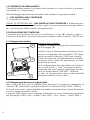
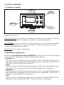
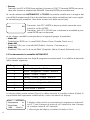
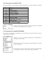
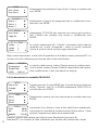
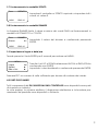
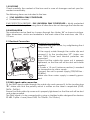
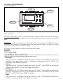
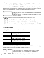
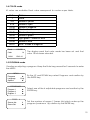
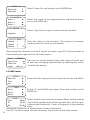
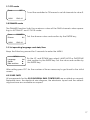
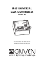
IP65 UNIVERSAL
DMX CONTROLLER
AD4110
Manuale di istruzioni
Instructions manual
INDICE
1.0 CONTENUTO DELL’IMBALLAGGIO
2.0 INSTALLAZIONE DEL CONTROLLER
2.1 Collegamento elettrico
2.2 Collegamento del cavo di segnale DMX
3.0 USO DEL CONTROLLER
3.1 Pannello di controllo
3.2 Modalità di funzionamento
3.3 Funzionamento in modalità AUTOMATICO
3.4 Funzionamento in modalità COLORI
3.5 Funzionamento in modalità PROGRAMMA
3.6 Funzionamento in modalità OROLOGIO
3.7 Funzionamento in modalità SPENTO
3.8 Funzionamento in modalità DIMMER
3.9 Impostazione lingua e data/ora
4.0 PARTI DI RICAMBIO
5.0 GARANZIA
6.0 NORMATIVE
7.0 INFORMAZIONI TECNICHE
2
Pag.
4
4
4
4
5
5
5
6
7
7
8
9
9
9
9
10
10
10
INDEX
1.0 PACKING
2.0 INSTALLATION
2.1 Electrical connection
2.2 DMX Signal cable connection
3.0 USE OF THE CONTROLLER
3.1 Control panel
3.2 Function mode
3.3 AUTOMATIC mode
3.4 COLOR mode
3.5 PROGRAM mode
3.6 TIMER mode
3.7 OFF mode
3.8 DIMMER mode
3.9 Set operating language and date/time
4.0 SPARE PARTS
5.0 WARRANTY CONDITIONS
6.0 COMPLIANCE
7.0 TECHNICAL INFORMATION
Page
12
12
12
12
13
13
13
14
15
15
16
17
17
17
17
18
18
18
3
1.0 CONTENUTO DELL’IMBALLAGGIO
Controllate attentamente il contenuto del cartone e, in caso di danni al prodotto,
contattate il Vs. trasportatore.
Nell’imballaggio del presente controller sono contenuti i seguenti prodotti:
n° 1 IP65 UNIVERSAL DMX CONTROLLER
n° 1 Manuale di Istruzioni
GRADO DI PROTEZIONE IP65 - IP65 UNIVERSAL DMX CONTROLLER è totalmente protetto contro la penetrazione di polveri. I getti d’acqua, provenienti da ogni direzione, non arrecano effetti dannosi all’apparecchio.
2.0 INSTALLAZIONE DEL CONTROLLER
Il controller può essere fissato con 4 viti attraverso i 4 fori “A” indicati in figura 1.
L’interasse di foratura, stampato nella parte posteriore della scatola,è 125x170 mm.
2.1 Collegamento elettrico
B
C
A
D
Apertura del controller:
- Togliete il coperchio principale rimuovendo le 4
viti di fissaggio “B”;
Inserite il cavo di alimentazione attraverso il pressacavo e collegatelo alla morsettiera “C” rispettando la polarità indicata (GND, Fase, Neutro).
Al fine di assicurare l’impermeabilità al prodotto,
accertarsi che il dado del pressacavo sia adeguatamente stretto.
Per il collegamento alla rete elettrica è necessario un cavo 3 poli x 1,5 mm2 di sezione minima.
Collegate alla rete facendo attenzione alla tensione di alimentazione (230/240V - 50/60Hz).
La linea di alimentazione deve essere protetta
mediante corretta messa a terra.
2.2 Collegamento del cavo di segnale DMX
Dopo aver inserito il cavo di segnale DMX attraverso il passacavo, collegatelo al
morsetto “D” rispettando la polarità indicata sull’etichetta (GND, DATA-, DATA+).
Al fine di assicurare l’impermeabilità al prodotto, accertarsi che il dado del pressacavo sia adeguatamente stretto.
Il segnale DMX deve essere collegato utilizzando un cavo schermato progettato
per congegni RS-485, 2 poli + calza (Calza: GND - Polo1: Data+ - Polo2: Data-).
4
3.0 USO DEL CONTROLLER
3.1 Pannello di controllo
UP
ENTER
DISPLAY
ESC
DOWN
Significato dei tasti:
TASTI UP e DOWN: permettono di evidenziare uno dei campi visualizzati sul display,
oppure di incrementare o diminuire il valore di un campo selezionato.
TASTO ENTER: se premuto quando il campo evidenziato è un sottomenu permette
di entrare nel sottomenu; se premuto quando il campo evidenziato è un dato,
conferma il valore di quel campo.
TASTO ESC: torna al menu precedente.
3.2 Modalità di funzionamento
Il dispositivo IP65 UNIVERSAL DMX CONTROLLER può funzionare in 5 diverse modalità
a cui si accede utilizzando le funzioni descritte qui di seguito.
• Automatico
Premete i tasti UP o DOWN per portare il cursore su FUNCT. Premete ENTER per accedere alle funzioni e selezionate uno degli 8 programmi automatici ( da AUTOM.1 a
AUTOM.8). Premete ENTER per confermare.
• Colori
Premete i tasti UP o DOWN per portare il cursore su FUNCT. Premete ENTER per accedere alle funzioni e e selezionate COLOR. Premete ENTER per confermare.
• Programma
Premete i tasti UP o DOWN per portare il cursore su FUNCT. Premete ENTER per accedere alle funzioni e selezionate uno dei 4 programmi configurabili ( da PROGR.1 a
PROGR.4). Premete ENTER per confermare.
• Timer
Premete i tasti UP o DOWN per portare il cursore su FUNCT. Premete ENTER per accedere alle funzioni e selezionate TIMER. Premete ENTER per confermare.
5
• Dimmer
Premete i tasti UP o DOWN per portare il cursore su FUNCT. Premete ENTER per accedere alle funzioni e selezionate DIMMER. Premete ENTER per confermare.
Se avete selezionato AUTOMATICO o COLORI è possibile modificare la mappa dei
canali DMX selezionando il tipo di proiettore che volete controllare (nel caso vogliate controllare più proiettori, dovranno essere tutti dello stesso tipo).
Mode
003
Premete i tasti ESC+ENTER e dopo qualche secondo comparirà la scritta MODE.
Premete i tasti UP o DOWN per cambiare la modalità e premete ENTER per confermare.
Le tre diverse modalità corrispondono ai seguenti gruppi di proiettori:
• Modo 001
Proiettori led RGB con 4 canali DMX (Dawn, Dune, Parade, Deck, ecc).
• Modo 002
Proiettori CYM con 3 canali DMX (Trident, Vesuvio, Colosseo,ecc).
• Modo 003
Proiettori CYM con 5 o 6 canali DMX (Graphite, Stelvio, Everest, Kolorado, ecc).
3.3 Funzionamento in modalità AUTOMATICO
E’ possibile selezionare uno degli 8 programmi preimpostati, il cui effetto è descritto
dalla tabella seguente.
N° Programma
1
2
3
4
5
6
7
8
Effetto
Rosso - Magenta - Giallo
Rosso - Magenta - Giallo - Bianco
Verde - Ciano - Giallo
Verde - Ciano - Giallo - Bianco
Blu - Ciano - Magenta
Blu - Ciano - Magenta - Bianco
Colori base
Colori base + Bianco
La durata delle scene colore (Pausa) e della velocità di cambio colore (Fade), è
impostabile dall’operatore modificando i valori visualizzati sul display.
6
Funz.
AUTOM.1
Tempo pausa
3s
Tempo Fade
3s
14/04
15:23:21
Il display indica che è in esecuzione il programma automatico N°1; che il tempo di pausa è di 3 secondi e che il tempo
di cambio colore è di 3 secondi.
L’ultima riga del display visualizza la data e l’ora.
3.4 Funzionamento in modalità COLORI
Sono disponibili 61 colori. Ad ogni valore corrisponde un colore indicato in tabella.
Valore
1
2-8
9-15
16-22
23-29
30-35
36-42
43-48
49-55
56-61
Funz.
Colore
14/04
Colore
Bianco
Tonalità di giallo
Tonalità di azzurro
Tonalità di magenta
Tonalità di rosso
Tonalità di arancione
Tonalità di verde
Verde chiaro-Ton. di Blue
Tonalità di Blue
Blu/Tonalità di magenta
COLORE
18
15:23:21
Il display indica che è settato il funzionamento in modalità
colori e che è selezionato il colore 18.
3.5 Funzionamento in modalità PROGRAMMA
Per creare o modificare un programma, tenete premuto il tasto Enter per 5 secondi per entrare nel MENU.
----------MENU---------Programmi
►
Lingua
Ital.
Opzioni
►
-----PROGRAMMI----Program 1
►
Program 2
►
Program 3
►
--------PROG. -1-------Num. Scene
6
Imp. Scena
►
Tramite i tasti UP e DOWN selezionate PROGRAMMI e
confermate con ENTER;
Selezionate uno dei 4 programmi personalizzabili e confermate con ENTER;
Impostate il numero di scene (Num. Scene) che compongono il programma (Max 16) e confermate con ENTER;
7
--------PROG. -1-------Num. Scene
6
Imp. Scena
►
------SCENE-P.1------Scena 1
►
Scena 2
►
Scena 3
►
---P.1--SCENA----1---Imp. Canali
►
Copia Da
1
----P1--S-1--DMX-----Canale
1
3
Canale
2
7
Canale
3
10
Selezionate Impostazione Scena (Imp. Scena) e confermate
con ENTER;
Selezionate la Scena da programmare o modificare e confermate con ENTER;
Selezionate COPIA DA per copiare una scena già creata o
IMP. CANALI per crearne una nuova e confermate con
ENTER;
Se avete selezionato IMP. CANALI vi troverete nella videata
riportata qui a lato. Assegnate i valori ai canali, tenendo
conto di quanti canali occupa ogni proiettore.
Dopo avere impostato i canali di tutti i proiettori e di tutte le scene, premete ESC un
numero di volte sufficiente per tornare alla schermata iniziale.
Funz.
PROGR.1
Tempo pausa
10s
Tempo Fade
6s
14/04
15:23:21
La durata delle scene colore (Tempo pausa) e della velocità di cambio colore (Tempo Fade) è impostabile dall’operatore modificando i valori visualizzati sul display.
3.6 Funzionamento in modalità OROLOGIO
----------MENU---------Data e Ora
►
Orologio
►
Info
►
----------TIMER---------Zona 1
►
Zona 2
►
Zona 3
►
---------ZONA-1--------Dalle
00:00
Alle
07:30
Modalità
COL50
8
Tenete premuto il tasto ENTER per 5 secondi per entrare nel
MENU. Tramite i tasti UP e DOWN selezionare OROLOGIO e
confermate con ENTER;
Selezionate la prima zona da impostare e e confermate con
ENTER;
Impostate l’ora d’inizio e l’ora di fine della Zona selezionata.
Impostate la modalità di funzionamento (Automatico, Colori
oppure Programma) della zona selezionata;
Eseguire questa operazione per tutte le zone desiderate (massimo 8).
Premere ESC un numero di volte sufficiente per tornare alla schermata iniziale.
3.7 Funzionamento in modalità SPENTO
Funz.
14/04
SPENTO
15:23:21
Impostare il controller su SPENTO equivale a impostare tutti i
canali sul valore 0.
3.8 Funzionamento in modalità DIMMER
La funzione DIMMER limita il valore massimo dei canali DMX nei funzionamenti in
modalità AUTOMATICO e COLORI.
Funz.
Dimmer
14/04
DIMMER
0%
15:23:21
Impostate il valore del dimmer e confermate premendo
ENTER.
3.9 Impostazione lingua e data/ora
Tenete premuto il tasto ENTER per 5 secondi per entrare nel MENU.
----------MENU---------Lingua
Ital.
Opzioni
►
Data e Ora
►
Tramite i tasti UP e DOWN selezionare LINGUA o DATA/ORA e
confermate con ENTER;
Impostate i valori desiderati e confermate premendo ENTER.
Premere ESC un numero di volte sufficiente per tornare alla schermata iniziale.
4.0 PARTI DI RICAMBIO
Tutti i componenti del IP65 UNIVERSAL DMX CONTROLLER sono disponibili come parti
di ricambio su richiesta.
Le viste esplose, lo schema elettrico, il diagramma elettronico e la brochure promozionale del prodotto sono disponibili su richiesta.
9
5.0 GARANZIA
• Ogni articolo prodotto dalla ditta italiana GRIVEN Srl è stato assemblato e costruito in conformità alle vigenti norme e normative CE.
• Ogni singolo prodotto e componente sono stati testati prima dell’assemblaggio
finale ed ogni prodotto è sottoposto ad un controllo di qualità interno prima di
essere spedito.
• GRIVEN Srl garantisce la buona qualità e realizzazione dei propri prodotti e si
impegna a riparare o sostituire a propria discrezione, nel più breve tempo possibile, qualsiasi parte che – durante il periodo di garanzia – mostri difetti di costruzione, assemblaggio o materiale.
• La garanzia è valida per la durata di 12 (dodici) mesi dalla data di consegna del
prodotto.
• GRIVEN Srl non risponde dei danni riportati dal prodotto durante il trasporto oppure derivanti da un utilizzo improprio o da un’inappropriata manutenzione dello
stesso.
• Sono escluse dalla presente garanzia tutte le parti considerate di consumo o soggette a normale logorio.
• Il cliente dovrà restituire le parti difettose alla GRIVEN Srl a suo carico e rischio.
• Le parti riparate o sostituire verranno spedite dalla GRIVEN ex-factory.
• Per ogni controversia sarà competente il foro di Mantova (Italia) in conformità
alla relativa giurisdizione italiana.
6.0 NORMATIVE
• L’apparecchio soddisfa i requisiti della normativa EN60598-1 EN60598-2-17.
• L’apparecchio soddisfa i requisiti della direttiva 2002/95/CE (RoHS).
7.0 INFORMAZIONI TECNICHE
Dimensioni
IP65 UNIVERSAL DMX CONTROLLER
Peso
Tensione nominale
Frequenza nominale
Grado di protezione
Temperatura ambiente
10
179x154x90
mm
230/240
Vac
2
50/60
IP65
-20 / 40
Kg
Hz
°C
NOTE
11
1.0 PACKING
Check carefully the content of the box and in case of damage contact your forwarder immediately.
The following items are included in the box:
n° 1 IP65 UNIVERSAL DMX CONTROLLER;
n° 1 Instructions manual.
IP65 PROTECTION DEGREE - IP65 UNIVERSAL DMX CONTROLLER is totally protected
against dost. Water spills coming from all directions do not damage the transformer.
2.0 INSTALLATION
The controller can be fixed by 4 screws through the 4 holes “A” as shown in picture.
Holes dimensions, which are readable in the back side of the main box, are 125 x
170 mm.
2.1 Electrical Connection
B
C
A
D
Opening the controller:
- Remove the main cover, by untightening the 4
fixing screws “B”;
Fit the supply cable through the cable clip and
connect it to the junction-box “C”. Make sure
that GND, Phase and Neutral polarities are
respected.
Ensure that the cable clip screw nut is properly
tightened, so that the unit will be dust and water
proofed.
A 3 poles x 1.5 mm² (minimum section) is needed
for connection to mains supply.
Connect the unit to power supply (230/240Vac 50/60Hz).
Make sure than mains supply is correctly grounded.
2.2 DMX signal cable connection
Fit the DMX signal cable through the cable clip and connect it to the junction-box
“D”. Make sure that the polarity which is written on the label is respected (GND,
DATA-, DATA+).
Ensure that the cable clip screw nut is properly tightened, so that the unit will be dust
and water proofed.
The DMX signal is to be connected by using a shielded cable designed for devices
RS-485, 2-pole + hose (Hose:GND, Pin1:Data+, Pin1:Data-).
12
3.0 USE OF THE CONTROLLER
3.1 Control panel
UP
ENTER
DISPLAY
ESC
DOWN
Keys functions:
UP and DOWN Keys: The UP and DOWN keys allow to point out one of the areas
which is visualized in the display, or increase or decrease the value of a selected
field.
ENTER Key: if pressed when the pointed out field is a submenu, the ENTER key allows
to enter the submenu; if pressed when the pointed out field is a datum, this key
allows to confirm the value of that field.
ESC Key: this key allows to return to the previous menu.
3.2 Function mode
IP65 UNIVERSAL DMX CONTROLLER can work in 5 different modes, which are accessible by using the functions described here below:
• Automatic
Press the keys UP or DOWN to lead the cursor to FUNCT. Press ENTER to access the
functions and select one of the 8 automatic programmes (from AUTOM.1 to
AUTOM.8). Press ENTER to confirm.
• Colours
Press the keys UP or DOWN to lead the cursor to FUNCT. Press ENTER to access the
functions and select COLOR. Press ENTER to confirm.
• Programme
Press the keys UP or DOWN to lead the cursor to FUNCT. Press ENTER to access the
functions and select one of the 4 programmes which is possible to set up (from
PROGR.1 to PROGR.4). Press ENTER to confirm.
• Timer
Press the keys UP or DOWN to lead the cursor to FUNCT. Press ENTER to access the
functions and select TIMER. Press ENTER to confirm.
13
• Dimmer
Press the keys UP or DOWN to lead the cursor to FUNCT. Press ENTER to access the
functions and select DIMMER. Press ENTER to confirm.
If you have selected AUTOMATIC or COLOR, it is possible to modify the map of the
DMX channels by selecting the type of unit which you want to control (in case you
want to control more units, they will all have to be of the same type).
Mode
003
Press the keys ESC+ENTER and after a few seconds the writing
MODE will appear.
Press the keys UP or DOWN to change the mode and press
ENTER to confirm.
The three different modes correspond to the following groups of units:
• Mode 001
LED RGB units with 4 DMX channels (Dawn, Dune, Parade, Deck, etc).
• Mode 002
CYM units with 3 DMX channels (Trident CYM 150, Vesuvio OS CYM 250, etc).
• Mode 003
CYM units with 5 or 6 DMX channels (Graphite, Stelvio CYM 300, Everest CYM 900,
Kolorado, etc).
3.3 AUTOMATIC mode
It is possible to select one of the 8 preset programs, whose effect is described in the
following table.
Program N°
1
2
3
4
5
6
7
8
Effect
Red - Magenta - Yellow
Red - Magenta - Yellow - White
Green, Cyan, Yellow
Green, Cyan, Yellow + White
Blue, Cyan, Magenta
Blue, Cyan, Magenta + White
All colors
All colors + White
The user can set the length of the color scenes (Pause) and of the color changing
speed (Fade) by adjusting the values visualized on display.
14
Funct.
AUTOM.1
Pause Time
3s
Fade Time
3s
14/04
15:23:21
The display reads that: automatic program no.1 is being
executed, pause time is 3 seconds and fade time is 3
seconds.
The last line in the display reads date and time.
3.4 COLOR mode
61 colors are available. Each value corresponds to a color as per table.
Value
1
2-8
9-15
16-22
23-29
30-35
36-42
43-48
49-55
56-61
Funct.
Color
14/04
Colour
White
Shade of yellow
Shade of cyan
Shade of magenta
Shade of red
Shade of orange
Shade of green
Light green - Shade of Blue
Shade of Blue
Blue / Shade of magenta
COLOR
18
15:23:21
The display reads that color mode has been set and that
color 18 has been selected.
3.5 PROGRAM mode
Creating or adjusting a program. Keep the Enter key pressed for 5 seconds to enter
the MENU.
----------MENU---------Programs
►
Language
Engl.
Options
►
-----PROGRAMS-----Program 1
►
Program 2
►
Program 3
►
--------PROG. -2-------Scenes No.
6
Scene Set
►
By the UP and DOWN keys select Programs and confirm by
the ENTER key;
Select one of the 4 adjustable programs and confirm by the
ENTER key;
Set the number of scenes ( Scenes No) which make up the
program (maximum 16); confirm by the ENTER key;
15
--------PROG. -2-------Scenes No.
6
Scene Set
►
-----P.2-SCENES-----Scene 1
►
Scene 2
►
Scene 3
►
---P.2--SCENE----1---Copy from
1
----P2--S-1--DMX-----Channel
1
3
Channel
2
7
Channel
3
10
Select Scene Set and confirm by the ENTER key;
Select the scene to be programmed or adjusted and confirm by the ENTER key;
Select Copy from to copy a scene already created.
Give the values to the channels. The number of channels
used by each unit must be considered.
After setting the channels of all units and of all scenes, press ESC for the number of
times necessary to get back to the initial screen.
Funct.
PROGR.1
Pause Time
10s
Fade Time
6s
14/04
15:23:21
The user can set the length of the color scenes (Pause) and
of the color changing speed (Fade) by adjusting the values
visualized on display.
3.6 TIMER mode
----------MENU---------Date-Time
►
Timer
►
Info
►
----------TIMER---------Zone 1
►
Zone 2
►
Zone 3
►
---------ZONE-1--------From
00:00
To
07:30
Set
COL50
16
Keep the Enter key pressed for 5 seconds to enter the MENU;
By the UP and DOWN keys select Timer and confirm by the
ENTER key;
Select the first zone to be set and press Enter. Set the starting
time and the ending time of the selected Zone. Set the operating mode (Automatic, Colors or Program) of the selected
zone.
Perform this action for all desired zones (maximum 8 zones).
Press ESC for the number of times necessary to get back to the initial screen.
3.7 OFF mode
Funct.
OFF
14/04
15:23:21
To set the controller to Off means to set all channels to value 0.
3.8 DIMMER mode
The DIMMER function limits the maximum value of the DMX channels when operating in AUTOMATC and COLOR mode.
Funz.
Dimmer
14/04
DIMMER
0%
Set the dimmer value and confirm by the ENTER key;
15:23:21
3.9 Set operating language and date/time
Keep the Enter key pressed for 5 seconds to enter the MENU.
----------MENU---------Language
Ital.
Option
►
Date and time
►
By the UP and DOWN keys select LANGUAGE or DATE/TIME
and confirm by the ENTER key. Set the value and confirm by
the ENTER key;
After setting press ESC for the number of times necessary to get back to the initial
screen.
4.0 SPARE PARTS
All components for the IP65 UNIVERSAL DMX CONTROLLER are available on request.
Exploded views, the electrical wire diagram, the electronic layout and the advertising brochure are available on request.
17
5.0 WARRANTY CONDITIONS
• Each product manufactured by GRIVEN srl of Italy is assembled and built in accordance to current CE conformity rules and regulations.
• Every single product and component has been tested before the final assembling
and all products must pass the in-house quality control before they are shipped.
• GRIVEN srl of Italy guarantees the good quality and manufacture of the products
and undertakes to repair or supply again, according to his opinion and free of
charge, within the shortest time possible, any part that shows - during the guarantee period - defects of constructions, manufacture or material.
• The guarantee is valid for 12 (twelve) months starting from the delivery date of the
products.
• GRIVEN srl of Italy does not respond for damages occurred to the units during
transport and for irrational use and inaccuracy in regular maintenance of the
products.
• The guarantee excludes all consumables.
• The customer will take care of the return of the faulty parts to GRIVEN srl of Italy,
at his own charge and risk.
• The parts which have been repaired or replaced are sent by GRIVEN srl of Italy exfactory.
• For any dispute, the Court of Mantova (Italy) will be competent and in conformity with relevant jurisdiction the Italian Law is enforced for any controversy.
6.0 COMPLIANCE
• Product in compliance with EN60598-1 EN60598-2-17.
• Product in compliance with 2002/95/CE (RoHS).
7.0 TECHNICAL INFORMATION
Dimension
IP65 UNIVERSAL DMX CONTROLLER
Weight
Operating voltage
Operating frequency
Protection rating
Operating temperature
18
179x154x90
mm
230/240
Vac
2
50/60
IP65
-20 / 40
Kg
Hz
°C
Importanti informazioni per il corretto riciclaggio/ smaltimento di questa apparecchiatura
La direttiva Europea 2002/96/CE sui rifiuti di apparecchiature elettroniche (RAEE), prevede che gli apparecchi illuminanti non debbano essere smaltiti nel normale flusso dei rifiuti solidi urbani. Gli apparecchi
dismessi debbono essere raccolti separatamente per ottimizzare il tasso di recupero e riciclaggio dei
materiali che li compongono ed impedire potenziali danni per la salute e l’ambiente.
Il simbolo del cestino barrato è riportato su tutti i prodotti per ricordare gli obblighi di raccolta separata.
Per ulteriori informazioni sulla corretta dismissione delle apparecchiature, i detentori potranno rivolgersi al
servizio pubblico preposto o ai rivenditori.
Important information for the correct recycle/treatment procedures of this equipment
The European Directive 2002/96/EC on Waste Electrical and Electronic Equipment (WEEE), requires that
old lighting fixtures must not be disposed of the normal unsorted municipal waste stream. Old appliances
must be collected separately in order to optimise the recovery and recycling of the materials they contain and reduce the impact on human health and the environment.
The crossed out “wheeled bin” symbol on the product reminds you of your obligation, that when you
dispose of the appliance it the must be separately collected.
Consumer should contact their local authority or retailer for information conceming the correct disposal of
their old appliance.
19
Via Bulgaria, 16 - 46042 CASTEL GOFFREDO (MN) - Italy
Telefono 0376/779483 - Fax 0376/779682 - 0376/779552
http://www.griven.com/ e-mail [email protected]
http://www.griven.it/ e-mail [email protected]
User’s manual rel. 1.00