1
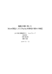
OPERATING MANUALE MANUAL D'USO Operating Manual Manuale d'uso English Italiano Telecomando wireless Handset Wireless Mode D’emploi Combiné sans fil Français Bedienungsanleitung Drahtloses Handgerät Deutsch Bedieningsaanwijzing Draadloos handapparaat Nederlands Manual De Instrucciones Auricular Inalámbrico Español Руководство По Зксплуатации Беспроводное Дистанционное Управление Pycckий Kullanım Kılavuzu Kablosuz Kulaklık Türkçe Εγ�ειρίδι� �δηγιών Ασύρματη �ειρ�συσκευή Ελληνικά Manual De Funcionamento Aparelho Sem Fios Portugues OM-NET3C-0411(0)-SIESTA Part No.: R08019036598 TELECOMANDO ARCWA ARCWA OUTLOOK i Batteria Battery 1) AAA.R03 1) Tipo: Type: AAA.R03 2) 2) Quantità: Quantity:2 2pezzi pieces Istruzioni per lo smaltimento Disposal Requirements Le batterie fornite con il telecomando sono contrassegnate da questo simbolo. Ciò The batteries supplied with the controller are marked with this symbol. significa che le batterie non devono mischiate a rifiuti domestici non differenziati. This means that the batteries shallessere not be mixed with unsorted household waste. Se sotto al simbolo è presente una formula chimica, tale formula indica che la batteria If a chemical symbol is printed beneath the symbol, this chemical symbol means that contiene metalli pesanti oltre una determinata Formule chimiche possibili: the battery contains a heavy metal above a concentrazione. certain concentration. Pb: piombo (>0,004%) Possible chemical symbols are: n Pb: lead (>0,004%) Le batterie usate devono smaltite presso centritreatment specializzati nel riutilizzo. Assicurarsi che il prodotto Waste batteries must beessere treated at a specialized facility for re-use. By ensuring correct venga smaltito in maniera corretta potential per evitarenegative potenziali conseguenze negative per l’ambiente e la salute. disposal, you will help to prevent consequences for the environment and human Contattare le autorità locali perlocal maggiori informazioni. health. Please contact your authority for more information. are all together 14 keysè on the ARCWA wired controller. IlThere telecomando a filo ARCWA dotato di 14 tasti. No N. 1. KEY TASTO ON/OFF ON/OFF FUNCTION FUNZIONE On/Off the unit with dell'unità overriding all the timer settings Accensione/spegnimento con esclusione di tutte le impostazioni del timer 2. SLEEP SLEEP Activate/deactivate Sleep function Attivazione/disattivazione della funzione Sleep 3. FAN FAN Select Fan speedsvelocità controldel (Auto/High/Med/Low) Selezione controllo ventilatore (Auto/Alta/Media/Bassa) 4. MODE MODE Selectcontrollo operating control (Cool/Heat/Dry/Fan) Selezione modalità diModes funzionamento (Raffrescamento/Riscaldamento/Deumidificazione/Ventilazione) 5. SET TEMP FRECCIA SU UP Increase della set temperature in °C or °Fin °C o °F Aumento temperatura impostata 6. SET TEMP FRECCIA GIÙ DOWN Decrease set temperature in impostata °C or °F in °C o °F Diminuzione della temperatura 7. SWING SWING Activate/deactivate Swing control. Attivazione/disattivazione controllo oscillazione 8. ONTIMER TIMER ON Enable/disable the Event 1, 2 di and 3 ON TIMER mode Attivazione/disattivazione modalità impostazione TIMERsetting ON Evento 1, 2 e 3 9. OFFTIMER TIMER OFF Enable/disable the Event 1, 2diand 3 OFF TIMER setting Attivazione/disattivazione modalità impostazione TIMER OFF Eventomode 1, 2 e 3 10. TIMERACTIVE ACTIVE TIMER Activate/deactivate all set Attivazione/disattivazione di timers tutti i timer impostati 11. CLOCK CLOCK Enable/disable the Real modalità Time Clock (RTC) settingreale mode Attivazione/disattivazione Orologio in tempo (RTC) 12. DAY DAY 13. HOUR HOUR 14. MINUTE MINUTE a)Selezione Select the day for or timer RTC setting a) giorno per RTC impostazione o timer Enable/disable FAN Keyblocco lock tasto FAN b) Attivazione/disattivazione a)Selezione Select the for RTC or timer settings a) orahour impostazione RTC o timer Set Overridefunzione functiondifor 1, 2 or 4manuale hours per 1, 2 o 4 ore b) Impostazione intervento a)Selezione Select the minute for RTC orRTC timer settings a) minuti impostazione o timer Enable/disable key lockblocco tasti b) Attivazione/disattivazione N.B.: Funzione di intervento Note : Override Function manuale Premendo una volta il tasto si attiva the la funzione intervento ora. Nell'angolo in show alto Press the HOUR key onceHOUR, will activate overridedifunction formanuale 1 hour. per An 1indicator “H1” will a sinistra dello LCD l'indicazione "H1". di nuovo lo stesso tasto per on the top leftschermo corner of thecomparirà LCD. Press the same keyPremere again will increase the setting to impostare 2 hours. An 2 ore. Comparirà l'indicazione "H2". Premere il tasto una terza volta per impostare 4 ore. Comparirà indicator “H2” will be shown. Press the 3rd times increase the setting to 4 hours. An indicator “H4” l'indicazione "H4". Premendo nuovamente il tasto verrà la funzione di intervento manuale. will be shown. Subsequent press will deactivate thedisattivata override function. When Overridedifunction is activated, all thetutti timers willverranno bypassed and turn ON the unit accesa for a fix Quandothe la funzione intervento manuale è attiva, i timer bypassati e l'unità rimarrà periods of 1 hour, 2 hours or24ohours depends the selection, afterdel which will turned off. per un periodo prefissato di 1, 4 ore (in base allaon selezione) al termine qualeitl'unità si spegnerà. 1 IstruzioniInstruction originali ITALIANO Original ENGLISH 1.0 GUIDA OPERATING GUIDE OPERATIVA 1.1 1.1 Tasto ON/OFF ON/OFF Button 1.2 1.2 Tasto SLEEP SLEEP Button 1.3 1.3 FAN TastoButton FAN 1.4 1.4 1.5 1.5 1.6 1.7 1.6 1.7 Avvio dell'unità: •• Starting Operation: thel'unità unit isè spenta, turned premere off, press the ON/OFF When Quando il tasto ON/OFF.button. operation LED lights and theeunit is turned on. The Il LED di funzionamento si illumina l'unità si accende. •• Stopping Operation: Arresto dell'unità: thel'unità unit is turned premere on, press the ON/OFF The operation eLED is si extinguished When Quando è accesa, il tasto ON/OFF. Ilbutton. LED di funzionamento l'unità spengono. and control are turned off. Premere il tastobutton SLEEP to peractivate attivare the la relativa la modalità di risparmio Press SLEEP sleep funzione mode oroenergy saving mode. energetico. Press FAN button to select AUTO, HIGH, MEDIUM or LOW fan speed. Premere il tasto FAN per selezionare una delle seguenti velocità di ventilazione: AUTOMATICA, ALTA, MEDIA oButton BASSA. MODE Press the MODE button to switch operation from COOL, HEAT, DRY, FAN. Check the display to see in which mode the control is set. Tasto MODE Premere il tasto MODE per scegliere una delle seguenti modalità di funzionamento: ‘▲’ or ‘▼’ Set Temperature Button RAFFRESCAMENTO, RISCALDAMENTO, DEUMIDIFICAZIONE, VENTILAZIONE (COOL/HEAT/DRY/FAN). Press the temperature button and set the temperature of your choice. By pressing the ‘▲’ or Controllare la modalità di funzionamento impostata sul display. ‘▼’ button once, temperature changes by 1°C [or 1°F]. Temperature can be set within the range 16°C~30°C (61°F~86°F). Tasti difan impostazione della temperatura ‘’ o ‘’ During mode, temperature cannot be set. Premere i tasti di impostazione della temperatura fino a raggiungere desiderati. Premendo If pressing ‘▲’ and ‘▼’ together, the unit of temperature will changei valori from °C to °F and vice-versa. una volta il tasto ‘’ o ‘’, la temperatura cambia di 1°C [o 1°F]. SWING buttonpuò essere impostata in un intervallo compreso tra 16°C~30°C (61°F~86°F). La temperatura Press SWING button tonon activate the airimpostare sweep function. In modalità ventilazione, è possibile la temperatura. Se si premono i tasti ‘’ e ‘’ contemporaneamente, la temperatura passa da °C a °F e viceversa. Time Setting i) Set Real Time Clock Setting Tasto SWING Press CLOCK key one time will activate RTC setting mode. Pressing the same key again Premere il tasto SWING per attivare la funzione di oscillazione. will disable RTC setting mode. Under RTC setting mode, “SET CLOCK” will be shown on LCD and it will blink at 0.5 sec Impostazione interval. The orario RTC and Day setting can be changed by pressing DAY key, HOUR key or i) MINUTE Impostazione inno tempo reale key.Orologio If there is further time related (DAY, HOUR and MINUTE) key is pressed for Premere unathe volta il tasto CLOCK perthe attivare la modalità di impostazione RTC. Premere di nuovo 15 sec, unit will quit from CLOCK setting mode. lo stesso tasto per disattivarla. ii) 7-Day Timers QuandoProgrammable l'unità è in modalità RTC, comparirà sullo schermo LCD l'indicazione "SET CLOCK" e The unit has 3 event each event has an ONl'impostazione TIMER and RTC an eOFF TIMER. lampeggerà ad intervalli functions, di 0,5 secondi. È possibile modificare quella Press the timer key (ON TIMER or OFF TIMER) will enable Event 1 timer setting mode. giornaliera premendo i tasti DAY, HOUR o MINUTE. Se non viene premuto alcun tasto relativo Press the same key again will enable Event 2 timer setting mode. Press the 3rd times will all'impostazione dell'orario (DAY, HOUR e MINUTE) per 15 secondi, l'unità esce dalla modalità enable the Event 3 (Event handset) timer- setting mode. Subsequent key pressed the unit OROLOGIO. will quit from timer setting mode. ii) Timer settimanali programmabili All timers are event triggered timers and can be overridden by the ON/OFF button and L'unità può registrare 3 eventi; ciascun evento dispone di un TIMER di accensione e di un TIMER Override function. di spegnimento. Premere il tasto del timer (ON TIMER o OFF TIMER) per entrare in modalità impostazione timer per l'Evento 1. Premere di nuovo lo stesso tasto per entrare in modalità impostazione timer per l'Evento 2. Premere il tasto una terza volta per entrare in modalità impostazione timer per l'Evento 3 (Evento telecomando). Ulteriori pressioni del tasto faranno uscire l'unità dalla modalità impostazione timer. Tutti i timer vengono attivati da un evento e possono essere esclusi premendo il tasto ON/OFF o dalla funzione di Intervento manuale. 2 1.10 Blocco ventilatore 1.11 Battery Se si preme il tasto DAY per 3 volte di seguito entro 1,5 secondi, il simbolo del ventilatore (vedi sopra) Backup scomparirà e il relativo tasto potrà Premere il tasto DAY 3timer volte consecutive per Battery backup is used to non retain theessere RTCpremuto. and 7-days programmable settings during annullare il blocco ventilatore. power down. For unit without battery backup, the default setting will be 12:00 am the timer clear during power up. 1.11 Batteria di backup La batteria di backup viene utilizzata per memorizzare le impostazioni dei timer settimanali programmabili e della modalità RTC in mancanza di corrente. Per le unità che non dispongono di batteria di backup, l'impostazione predefinita è 12:00 e il timer viene annullato all'accensione. 3 ITALIANO ENGLISH iii) Set Impostazione timer per Evento 1 e Evento 2 iii) Event 1 and Event 2 Timers Under In modalità timer, comparirà schermo "SETatTIMER" e interval. timerimpostazione setting mode, “SET TIMER”sullo will be shownLCD on l'indicazione LCD and blink 0.5 sec lampeggerà ad intervalli di 0,5 secondi. For Event 1 Timer setting, ‘ ON’ or ‘ OFF’ indication will appear and digit “1” will be Per l'impostazione delleft timer relativo all'Evento alto aindication sinistra dello displayed on the top corner of the LCD. ‘1, nell'angolo ON’ or ‘ inOFF’ andschermo digit “2” will LCDdisplayed compariràduring l'indicazione ON’ osetting. ‘ OFF’ eThe il numero "1". ‘Durante l'impostazione del be Event ‘2 timer timer setting can be changed thru pressing o ‘ further OFF’ e time il numero "2". (DAY, È possibile timer relativo 2, comparirà l'indicazione the DAY key,all'Evento HOUR key or MINUTE key. If thereON’ is no related HOUR modificare l'impostazione del timer i tasti DAY, HOUR Se non viene and MINUTE) key is pressed, thepremendo unit will quit from the timero MINUTE. setting mode. premuto alcun tasto relativo all'impostazione dell'orario (DAY, HOUR e MINUTE), l'unità esce iv) Set Event 3 Timer via remote control (Optional) dalla modalità impostazione timer. This timer can be controlled separately thru remote control as well as ON TIMER or OFF iv) Impostazione timer Evento 3 tramite telecomando (opzionale) TIMER keys. Timer 3 can be set like timers 1 and 2 liketelecomando above except the DAY setting is Questo timer può essere controllato separatamente tramite oppure mediante not provided as/this everyday. An indicator “3” will display during i tasti ON TIMER OFFtimer TIMER.setting Il timeris3valid può essere impostato esattamente come i timer 1 e 2 the ON’ or ‘ OFF’ will blink at 0.5 sec interval during the Event 3 timer setting mode. ‘ sopradescritti; l'impostazione del GIORNO, però, non è disponibile poiché il timer 3 è valido tutti timer setting. If there is no futher time related (DAY, HOUR and MINUTE) key is pressed, i giorni. In modalità impostazione timer per l'Evento 3 comparirà l'indicazione "3". ‘Durante la the unit will quit from the timer setting mode. fase di impostazione del timer, la scritta ON’ o ‘ OFF’ lampeggerà ad intervalli di 0,5 secondi. The ON/OFF timer setting received from remote control will override the Event 3 timer Se non viene premuto alcun tasto relativo all'impostazione dell'orario (DAY, HOUR e MINUTE), setting from the unit. l'unità esce dalla modalità impostazione timer. Il timer diand accensione/spegnimento 1.8 Activating canceling timersimpostato tramite telecomando esclude il timer per l'Evento 3 impostato These timers willdall'unità. not triggered if the timer is not active. To activate the timers, press the TIMER ACTIVE key unit “TIMER ACTIVE” appears on LCD. This symbol is to indicate Event 1, Event and/or Event 3 timers are active. Pressing the same steps will deactivate the timers and 1.8 2Attivazione e annullamento dei timer “TIMER ACTIVE” symbol will disappear. Questi timer non scattano se il timer non è attivo. Per attivare i timer, premere il tasto TIMER ACTIVE Another method to cancel the timers setting is changed all the hour setting of the timers to fino a quando non appare "TIMER ACTIVE" sullo schermo LCD. Questo simbolo indica che il timer per null one by one. When the setting is null, the LCD display --:--, then this respective timer will l'Evento 1, 2 e/o 3 è attivo. Ripetendo gli stessi passaggi, i timer verranno disattivati e l'indicazione be disable. "TIMER ACTIVE" scomparirà. Lock 1.9 Key Un altro metodo per annullare i timer è quello di impostare le ore dei timer a 0, uno a uno. Una volta These key lockprocedura, function sullo to inhibit anyLCD setting change. MINUTE key 3 times eseguita questa schermo comparirà --:-- e ilPress relativothe timer sarà disabilitato. consecutively will activate key lock function, “KEYLOCK” will be shown on LCD. Upon all keys are locked, only ON/OFF key and MINUTE key can be pressed. To cancel the key 1.9 the Blocco tasti lock function, press the MINUTE key 3 times consecutively, the word “KEYLOCK” will be Questa funzione impedisce la modifica delle impostazioni. Premere il tasto MINUTE per 3 volte disappeared. consecutive per attivare il blocco tasti; sullo schermo LCD comparirà l'indicazione "KEYLOCK". Una voltaLock bloccati tutti i tasti, sarà possibile premere solo i tasti ON/OFF e MINUTE. Per annullare il blocco 1.10 Fan When the DAY key MINUTE is pressper 3 3times consecutively within"KEYLOCK" 1.5 sec, scomparirà the fan symbol (shown tasti, premere il tasto volte consecutive; la scritta dallo schermo. above) will disappear and fan key will be inhibit from pressing. Press the DAY key 3 times to cancel the fan lock function. 2.0 2.0 INSTALLAZIONEOF DELLCD TELECOMANDO CON SCHERMO LCD INSTALLATION REMOTE CONTROLLER 2.1 2.1 Accessories Accessori The following accessories are included together with this manual. If any part is missing, contact 2.2 2.2 Step-by-step guide passo i)Guida First, open passo up the casing of the LCD remote controller into its top and bottom case using a Il presente viene fornito completo dei seguenti accessori. Qualora non fossero presenti tutti i your dealermanuale immediately. componenti, rivolgersi 1 Remote controllerimmediatamente al rivenditore. Telecomando 2 screw 4.1 x 16 (2 pieces) & machine screw (2 pieces) Wooden Vite per legno 4,1 x 16 (2 pezzi) e vite per ferro (2 pezzi) 3 Instruction manual Manuale di istruzioni 4 Battery Batteria i) screwdriver. Prima di tutto,To aprire il telecomando LCD separandone la parte daslide quella posteriore do this, insert the screwdriver into the lowerfrontale slot and it in the outward servendosi di un cacciavite. Per farlo, inserire il cacciavite nella fessura in basso e far leva verso direction. l'esterno. ii) Fix the bottom case onto the wall with the 2 wooden screws provided. ii) Fissare la parte posteriore a parete usando le due viti per legno fornite. Then, insert the 4-pin connection wires (from main board) through the slot on the upper Inserire quindi il cavo di collegamento a 4 pin (dalla scheda principale) nella fessura in alto al center of the case as shown below. centro della piastrina, come mostrato in figura. iii) To select cooling only model or heatpump model, some adjustment required in the shunt iii) Per selezionare un modello solo raffrescamento o a pompa di calore, sarà necessario apportare jumper setting. alcune modifiche all'impostazione del ponticello di derivazione. iv) back lethe and case into place. two upper claws into their iv) Fasten Riassemblare duetop parti delbottom telecomando. Inserire i dueHook gancithe superiori nelle apposite fessure e respective slots and snap the lower part shut. incastrare la parte inferiore. Telecomando LCD LCDRemote (parte (Top case) frontale) Lower slot Fessura aprire for inferiore openingper LCD casing l'involucro del telecomando LCD Cavo di Connection collegamento wires 2 x Wooden 2 vitiscrew per legno LCD Remote Telecomando LCD (Bottom case) (parte posteriore) 4 Se vieneis rilevata un'anomalia, sul telecomando filo ARCWA inizierà a lampeggiare unthe codice errore. If there any abnormal condition detected,aARCWA wired controller will blink error code. CODICE ERRORERRORE CODE SIGNIFICATO MEANING 00 A1 A3 A5 A6 AH C4 C5 C7 C9 E1 E3 E4 E5 E6 E7 E8 E9 EA F3 F6 HO H3 H6 H7 H8 H9 J1 J3 J5 J6 J7 J8 J9 L1 L3 L4 L5 L8 L9 LC P1 P4 NORMAL NORMALE INDOORSCHEDA PCB ERROR ERRORE ELETTRONICA INT. DRAIN PUMP ABNORMAL MALFUNZIONAMENTO POMPA SCARICO CONDENSA ANTIFREEZE (COOLING)/HEAT EXCHANGER OVERHEAT ANTIGELO (RAFFRESCAMENTO) / SURRISCALDAMENTO SCAMBIATORE DI CALORE(HEATING) (RISCALDAMENTO) INDOOR FAN MOTORMOTORE ABNORMAL MALFUNZIONAMENTO VENTILATORE INT. ELECTRICAL AIR CLEANER ABNORMAL MALFUNZIONAMENTO PURIFICATORE ARIA ELETTRICO INDOOR APERTO/CORTOCIRCUITO HEAT EXCHANGER (1)TERMISTORE THERMISTOR SHORT/OPEN CIRCUITO SCAMBIATORE DI CALORE INT. (1) INDOOR APERTO/CORTOCIRCUITO HEAT EXCHANGER (2)TERMISTORE THERMISTOR SHORT/OPEN CIRCUITO SCAMBIATORE DI CALORE INT. (2) LOUVER LIMIT SWITCH ERROR ERRORE FINECORSA DEFLETTORI INDOOR ROOM THERMISTOR SHORT/OPEN CIRCUITO APERTO/CORTOCIRCUITO TERMISTORE AMB. INT. OUTDOOR PCBELETTRONICA ERROR ERRORE SCHEDA EST. HIGH PRESSURE PROTECTION PROTEZIONE ALTA PRESSIONE LOW PRESSURE PROTEZIONE BASSAPROTECTION PRESSIONE COMPRESSOR LOCK/COMPRESSORCOMPRESSORE OVERLOADED BLOCCO MOTOREMOTOR COMPRESSORE/SOVRACCARICO COMPRESSOR START-UP ERROR ERRORE AVVIO COMPRESSORE OUTDOOR DC FAN MOTOR LOCK BLOCCO MOTORE CC VENTILATORE EST. AC INPUT OVERINGRESSO CURRENT SOVRACORRENTE CA EXV ERROR ERRORE VALVOLA DI ESPANSIONE ELETTRONICA (EXV) 4 WAY VALVE ERROR ERRORE VALVOLA A 4 VIE DISCHARGE PIPE OVERHEAT SURRISCALDAMENTO LINEA DI MANDATA HEAT EXCHANGER SCAMBIATORE OVERHEAT DI CALORE SURRISCALDAMENTO COMPRESSOR SYSTEM ERRORE SENSORESENSOR DELL'IMPIANTO DEL ERROR COMPRESSORE HIGH PRESSURE SWITCH ERRORE PRESSOSTATO DI ALTAERROR COMPRESSOR FEEDBACK DETECTION ERROR ERRORE RILEVAMENTO RETROAZIONE COMPRESSORE FAN MOTOR MOTORE OVERLOADED/OVERCURRENT/SENSOR ABNORMAL SOVRACCARICO VENTILATORE/SOVRACORRENTE/MALFUNZIONAMENTO SENSORE AC CURRENT SENSOR ERROR ERRORE SENSORE CORRENTE CA OUTDOOR AIR THERMISTOR SHORT/OPEN CIRCUITO APERTO/CORTOCIRCUITO TERMISTORE ARIA EST. PRESSURE SENSOR ERROR ERRORE SENSORE DI PRESSIONE COMPRESSOR DISCHARGE PIPEERRATO THERMISTOR CIRCUITO APERTO/CORTOCIRCUITO/POS. TERMISTORESHORT/OPEN/MISPLACED LINEA DI MANDATA COMPRESSORE SUCTIONAPERTO/CORTOCIRCUITO PIPE THERMISTOR SHORT/OPEN CIRCUITO TERMISTORE LINEA DI ASPIRAZIONE OUTDOOR HEAT EXCHANGER THERMISTOR SHORT/OPEN CIRCUITO APERTO/CORTOCIRCUITO TERMISTORE SCAMBIATORE DI CALORE EST. SUBCOOLING HEAT EXCHANGER THERMISTOR SHORT/OPEN CIRCUITO APERTO/CORTOCIRCUITO TERMISTORE SCAMBIATORE DI CALORE SOTTORAFFR. LIQUID PIPE THERMISTOR SHORT/OPEN CIRCUITO APERTO/CORTOCIRCUITO TERMISTORE LINEA LIQUIDO GAS PIPEAPERTO/CORTOCIRCUITO THERMISTOR SHORT/OPEN CIRCUITO TERMISTORE LINEA GAS INVERTER OUTDOOR PCB ERROR ERRORE SCHEDA ELETTRONICA EST. INVERTER OUTDOOR CONTROL BOX OVERHEAT SURRISCALDAMENTO QUADRO ELETTRICO EST. HEAT SINK OVERHEAT SURRISCALDAMENTO DISSIPATORE IPM ERROR/IGBT ERRORE IPM/ERROREERROR IGBT INVERTER COMPRESSOR OVERCURRENT SOVRACORRENTE COMPRESSORE INVERTER COMPRESSOR OVERCURRENT PREVENTION PREVENZIONE SOVRACORRENTE COMPRESSORE COMMUNICATION ERROR (OUTDOOR CONTROL PCB INVERTER PCB) ERRORE DI COMUNICAZIONE (SCHEDA DI CONTROLLO EST. EAND SCHEDA INVERTER) OPEN PHASE OR VOLTAGE UNBALANCE FASE APERTA O SQUILIBRIO DI FASE HEAT SINK THERMISTOR SHORT/OPEN CIRCUITO APERTO/CORTOCIRCUITO TERMISTORE DISSIPATORE 5 ITALIANO ENGLISH 3.0 FAULT RICERCA GUASTI (solo Inverter) 3.0 DIAGNOSIS (For Inverter only) CODICE ERRORERRORE CODE MEANING SIGNIFICATO PJ U0 U2 U4 U7 UA UF UH CAPACITY ERRORE IMP. SETTING CAPACITÀ ERROR INSUFFICIENT GAS GAS INSUFFICIENTE DC VOLTAGE OUTRANGE OF RANGE TENSIONE CC FUORI COMMUNICATION ERROR ERRORE DI COMUNICAZIONE COMMUNICATION ERROR(SCHEDA (OUTDOOR CONTROLEST. PCB AND IPMIPM) PCB) ERRORE DI COMUNICAZIONE DI CONTROLLO E SCHEDA INSTALLATION ERROR ERRORE INSTALLAZIONE MANCATA NELL'INSTALLAZIONE DI CAVI E TUBAZIONI/CABLAGGIO ERRATO/GAS INSUFFICIENTE PIPING CORRISPONDENZA & WIRING INSTALLATION MISMATCH/WRONG WIRING/INSUFFICIENT GAS ANTIFREEZE (OTHER ANTIGELO (ALTRI LOCALI)ROOMS) 6