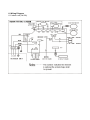
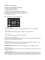
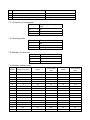
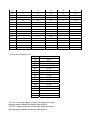
1
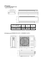
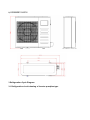
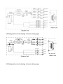
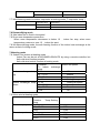
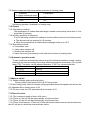
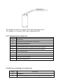
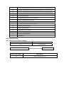
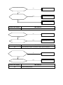
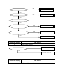
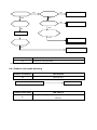
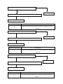
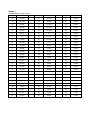
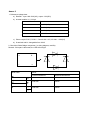
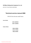
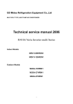
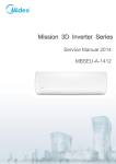
MULTI SPLIT TYPE, HEAT PUMP AIR CONDITIONERS
Technical service manual 2009
KSIM MULTI ZONE SERIES
R410A DC Inverter multi Series
Models
KSIM20912-H216
KSIM30912-H216
KSIM40912-H216
CONTENT
1. Product features
2. Dimensions
3. Refrigeration cycle diagram
4. Operation limits
5. Indoor unit combination
6. Wiring diagram
7. Electric control functions
8. Troubleshooting
Annex 1 Characteristic of temp. sensor
Annex 2 Reference data
1. Product features
Indoor unit
Operation by remote controller
Sensing by room temperature
Room temperature sensor.
Pipe temperature sensor.
Room temperature control
Maintain the room temperature in accordance w
ith the setting temperature.
Anti-freezing control in cooling
Prevent the water being frozen on evaporator by sensing the
evaporator pipe temperature in cooling mode
Time Delay Safety control
Restarting is for approx. 3 minutes..
Indoor fan speed control
high, med, low, breeze.
Two-direction air vane
The unit will decide the louver direction according to
operation mode.
Sleep mode auto control
Tele Remote control (Optional)
Self-diag. function
The fan is turn to low speed (cooling/heating).
The unit will be turn off at the seventh hour.
Anti-cold function
Independent dehumidification
The function is usually used in rainy days in
springtime or damp areas.
Prevent the cold wind at the
beginning of unit start.
Auto defrost
Air flow Direction control
The louver can be set at the desired position or
swing up and down automatically
Auto mode
The mode can be change by the room temperature.
Temp. Compensation
Auto-restart function
When the power supply is interrupted
and then restore, the air conditioners
automatically restore the previous
function setting.
Flexible wiring connection
Outdoor unit
Power relay control
The unit has 3 mins delay between continuously ON/OFF operations.
Low noise air flow system
Bird tail propeller fan makes the outdoor unit run more quietly.
Hydrophilic aluminum fin
The hydrophilic fin can improve the heating efficiency at operation mode.
4 way valve control
It is only operated in the heating operation mode except defrosting operation.
Anti-rust cabinet
Made from electrolytic zinc steel sheet and anti-rust coated components.
Valve protection cover
It protects the valves and prevents water from dripping.
Discharge pipe temperature protect
Driving heating at -15
2 Dimensions
2.1 KSIM MULTIZONE Series
Indoor unit 9K&12K
Dimension
W
H
D
9K
795
270
165
12K
845
286
165
Mode
2.2 Outdoor unit KSIM20912-H216 , KSIM30912-H216
b) KSIM40912-H216
3 Refrigeration Cycle Diagram
3.1 Refrigeration circuit drawing of inverter quadplex type
3.2 Refrigeration circuit drawing of inverter trinary type
Axial flow fan
Main
Capillary
Exhaust
temp. sensor
Condenser
4-way
valve
Coil temp.
sensor
Auxiliary
Capillary
Check
Valve
Capillary A
EXV A
Capillary B
EXV B
Liquid valve A
Filter A
Liquid valve B
Filter B
Capillary C
EXV C
Liquid valve C
flow fan
Evaporator
Filter C
Cross
Compressor
Indoor pipe out
temp. seneor A
Gas valve A
Indoor pipe out
temp. seneor B
Gas valve B
Indoor pipe out
temp. seneor C
Gas valve C
Outdoor Unit
3.3 Refrigeration circuit drawing of inverter binary type
Indoor Unit
Axial flow fan
EXVA
Exhaust
temp. sensor
Main
Capillary
Auxiliary
Capillary
Filter A Liquid valve A
Capillary A
EXVB
Filter B
Liquid valve B
Capillary B
Compressor
Indoor pipe out
temp. seneor A
Gas valve A
Indoor pipe out
temp. seneor B
Gas valve B
Indoor Unit
Outdoor Unit
4 Temperature Operation range
Indoor temperature
Outdoor temperature
Indoor temperature
Outdoor temperature
Indoor temperature
Outdoor temperature
Cooling mode
Heating mode
Dry mode
≥17
0 50
≤30
-15 24
10
0 43
5. Indoor units combination
5.1 Indoor unit combination for KSIM20912-H216
One unit Two unit
9
9+9 9+12
12
5.2 Indoor unit combination for KSIM30912-H216
One unit
Two unit
Three unit
9
9+9
9+12 9+9+9 9+9+12
12
12+12
5.3 Indoor unit combination for KSIM40912-H216
One unit
9
12
Two unit
9+9
9+12
12+12
Three unit
9+9+9
9+9+12
9+12+12
12+12+12
Evaporator
4-way
valve
Coil temp.
sensor
Cross flow fan
Condenser
Check
Valve
9+9+9+9
Four unit
9+9+9+12
9+9+12+12
6. Wiring Diagram
6.1 Indoor unit (9k/12k)
6.2 Outdoor unit (2 ZONE)
6.3 Outdoor unit (3 ZONE)
6.4 Outdoor unit (4 ZONE)
7 Electronic control function
7.1 Electric Control working environment.
7.1.1 Input voltage: 175~253V.
7.1.2 Input power frequency:50Hz.
7.1.3 Indoor fan normal working amp. is less than 1A.
7.1.4 Outdoor fan. Normal working amp. is less than 1.5A.
7.1.5 Four-way valve normal working amp. is less than 1A.
7.1.6 Swing motor: DC12V.
7.2 Icon explanation on indoor display board.
OPERRATION indicator
This indicator flashes after power is on and illuminates when the unit is in operation.
AUTO indicator
This indicator illuminates when the air conditioner is in AUTO operation.
TIMER indicator
This indicator illuminates when TIMER is set ON/OFF.
IONIZER (CLEAN AIR) indication lamp
Lights up when CLEAN AIR feature is activated and Ionizer can generate abundant anions
to fill the room with refreshing and natural air.
PRE-DEF. indicator
This indicator illuminates when the air conditioner starts defrosting automatically or when
the warm air control feature is activated in heating mode.
TURBO indication lamp
Lights up when select TURBO function on cooling operation or on heating operation.
FREQUENCY indicator
This indicator appears only when the compressor is in operation and indicates the current
operating frequency.
TEMPERATURE indicator
Usually it displays the temperature settings. When change the setting temperature, this
indicator begins to flash, and stops 20 seconds later. It displays the room temperature when
the air conditioner is in FAN only operation. When the unit stops operation, it returns to
original factory settings. The temperature indicator area will display “SC” when the self clean
function is started.
It also displays the malfunction code or protection code.
FAN SPEED indication lamp
Displays the selected fan speed: AUTO (nothing) and three fan speed levels: LOW, MED
and HIGH.
LED display control function.
Pressing “LED display” button on remote controller will turn off all displays on indoor unit,
while pressing once again, all displays will resume.
7.3 Outdoor unit’s digital display tube
There is a digital display tube in outdoor PCB.
7.3.1 Digital display tube display function
• In standby , The LED displays “ ”,
• In compressor operation, the LED display the frequency,
• In defrosting mode, The LED displays the frequency or “dF” each other for 2
seconds,
• In compressor pre-heating, The LED displays “ ”
• In protection or malfunction, the LED displays error code or protection code.
7.4 Outdoor unit point check function
There is a check switch in outdoor PCB.
Push the switch SW1 to check the states of unit when the unit is running. The digital display
tube will display the follow procedure when push SW1 each time:
Display
Remark
1
Indoor unit capacity demand code
2
Outdoor unit running mode code
3
Amendatory capacity demand code
4
Outdoor unit fan motor state
Off:0, Low speed:1, High speed:2
5
Evaporator outlet temp. for 1# indoor unit
Actual data
6
Evaporator outlet temp. for 2# indoor unit
Actual data
7
Evaporator outlet temp. for 3# indoor unit
Actual data
8
Evaporator outlet temp. for 4# indoor unit
Actual data
9
Condenser pipe temp.
Actual data
10
Ambient temp.
Actual data
11
Compressor discharge temp.
Actual data
12
Inverter current
Actual data
13
EXV open angle for 1# indoor unit
Actual data×8
14
EXV open angle for 2# indoor unit
Actual data×8
15
EXV open angle for 3# indoor unit
Actual data×8
16
EXV open angle for 4# indoor unit
Actual data×8
17
Outdoor unit DC Voltage
AD *472/255=Actual Voltage
18
Indoor unit number
The indoor unit can communicate with
Off:0, Cooling:1, Heating:2
outdoor unit well.
19
The last error or protection code
00 means no malfunction
20
The Compressor’s running frequency
29
――
Check point over
7.4.1 Frequency of compressor:
Display
30
-60
Frequency of compressor
(Hz)
30
Stand by
60
Display
0
1
2
Corresponding mode
Off
Cooling mode
Heating mode
7.4.2 Running mode:
7.4.3Number of indoor unit
Display
1
2
3
Number of indoor unit
1
2
3
7.4.4Outdoor ambient temp:
Corresponding
Display
Corresponding
Display
Corresponding temp.
Display
15
-7.5
50
10
80
25
16
-7
51
10.5
81
25.5
17
-6.5
52
11
82
26
18
-6
53
11.5
83
26.5
19
-5.5
53
11.5
84
27
20
-5
54
12
85
27.5
21
-4.5
55
12.5
86
28
22
-4
56
13
87
28.5
23
-3.5
57
13.5
88
29
24
-3
58
14
89
29.5
26
-2
59
14.5
90
30
27
-1.5
60
15
91
30.5
28
-1
61
15.5
92
31
29
-0.5
62
16
93
31.5
30
0
63
16.5
93
31.5
31
0.5
63
16.5
94
32
32
1
64
17
95
32.5
temp.
temp.
33
1.5
65
17.5
96
33
34
2
65
17.5
97
33.5
35
2.5
66
18
98
34
36
3
67
18.5
99
34.5
37
3.5
68
19
10.
35~40
38
4
69
19.5
11.
40~45
39
4.5
70
20
12.
45~50
40
5
71
20.5
13.
50~55
41
5.5
72
21
14.
55~60
42
6
73
21.5
15.
60~65
43
6.5
74
22
16.
65~70
44
7
75
22.5
45
7.5
75
22.5
46
8
76
23
47
8.5
77
23.5
48
9
78
24
49
9.5
79
24.5
7.4.5Current of outdoor unit
Display
60
65
70
75
80
85
90
100
110
120
130
140
150
200
Corresponding mode
8.0A
8.5A
9.1A
9.6A
10.1A
10.7A
11.2A
12.3A
13.4A
14.5A
15.6A
16.7A
17.9A
24A
7.4.6 No. 1 opening degree of electronic expansion valve:
Opening degree equals the display data times 8
7.4.7No. 2 opening degree of electronic expansion valve:
Opening degree equals the display data times 8
7.4.8No. 3 opening degree of electronic expansion valve:
Opening degree equals the display data times 8
7.5 Protection
7.5.1 3 minutes delay at restart for compressor.
7.5.2 Discharge temperature protection of compressor, compressor stops when the temp. of
discharge is more than 115 and last out 10 s. compressor runs when the temp. of
discharge is less than 90 .
7.5.3 When AC voltage ≤ 80V, Outdoor Unit stops operation and Outdoor LED displays
“E5”,. When AC voltage ≥ 100V, Outdoor Unit resumes operation.
7.5.4 Inverter module Protection , Inverter module Protection itself has a protection function
against current, voltage and temperature, and Indoor LED displays “P0”.
7.5.5 Sensor protection at open circuit and breaking disconnection
7.5.6 Fan Speed is out of control. When Indoor Fan Speed is too high(higher than High
Fan+300RPM)or too low(lower than 400RPM), the unit stops and Indoor LED displays “E3”,
and can’t return to normal operation automatically.
7.5.7 Cross Zero signal error warning. For If there is no Cross Zero signals in 4 minutes, the
unit stops and Indoor LED displays “E2”, and can’t return to normal operation automatically.
7.5.8 Current protection: when the current is more than ‘X’ A, the compressor stops. and
Outdoor LED diaplays “P3” for 30 seconds, and the unit will restart after 3 minutes.
(X is 12.5A for 18K 1x2 unit, is 14.5A for 27K 1x3 unit and is 20A for 36K 1x4 unit. )
7.5.9 Outdoor condenser high temperature protection: Under cooling mode, if T3>65 for 3
seconds, the compressor will stop. When T3<52 , the protection is not valid. And the unit
will restart after 3 minutes.
7.5.10 Pressure protection (just be available for 36K 1x4 unit): If low pressure is lower
21Psig, the compressor will stop and when low pressure is higher than 44Psig, the
compressor will restart. If high pressure is higher than 630Psig, the compressor will stop and
when high pressure is lower than 460Psig, the compressor will restart.
7.5.11 Compressor pre-heating function: When the outdoor temperature is lower than 3
and the compressor stops operation, the compressor enters into pre-heating condition.
When outdoor temp. is more than 5 or user operate it, pre-heating condition will finish.
7. 6 Fan-only mode
Fan speed is high/mid/low/ Auto
7.7 Cooling mode
7.7.1 Indoor fan keeps running, fan speed can be set in high/mid/low/ Auto:
7.7.2Auto fan at cooling mode: (T=Indoor Temp.-Setting Temp.)
Condition
Room temp. up
Room temp. down
Indoor fan speed
T<1.5
Low
1.5 <T<3.5
Mid.
T>3.5
High
T> 3
High
1 <T<3
Mid.
T<1
Low
7.7.3Anti-freezing control to indoor evaporator at cooling mode( T: evaporator temp. )
Evaporator Temp.
Compressor
T< 4
Off
T>8
On
7.8 Dehumidifying mode
7.8.1the indoor fan is fixed in low speed
7.8.2Low room temperature protection:
When room temperature decreases to below 10 , indoor fan stop, when room
temperature restores to over 12 , indoor fan start.
7.8.3At dehumidifying mode, the anti-freezing function of the indoor heat exchanger is the
same as that of cooling mode.
7.9Heating mode
7.9.1Indoor Fan actions at heating mode
Indoor Fan can be set at HIGH/MID/LOW/AUTO by using a remote controller, but
Anti-cold wind function prevails.
Anti-cold wind control function at heating mode
Condition
Indoor fan speed
T= Indoor exchanger
temp.
Indoor exchanger temp. T<34
Off
up
34 <T<37
Breeze
37 <T<44
Low speed
T> 44
Setting fan speed
Indoor exchanger temp. T> 38
Setting fan speed
down
33 <T<38
Low speed
24 <T<33
Breeze
T<24
Off
7.9.2Auto wind at heating mode
Condition
Indoor fan speed
T=Indoor
Temp.-Setting
Temp.
Room temp. up
T<1.5
High
1.5 <T<2.5
Mid.
T>2.5
Low
Room temp. down
T<1.0
High
1.0 <T<2.0
Mid.
T>2.0
Low
7.9.3Indoor evaporator high-temperature protection at heating mode
Condition
Compressor
T= Indoor exchanger temp.
T>63
Off
T<48
On
.
Defrosting operation (Available for heating only)
7.10 Defrost
7.10.1Defrosting condition:
The temperature of outdoor heat exchanger remains consecutively lower than -2°c for
more than 40 minutes,
7.10.2Ending condition of defrosting
If one of following conditions is satisfied, end the defrost and turn into heating mode:
a. The defrost time has reached to 10 minutes.
b. When the temperature of outdoor heat exchanger rises up to 15°C
7.10.3Defrosting Actions:
a. Compressor runs.
b. 4 way valve switches off,
c. Outdoor fan switches off
d. Indoor fan running according to anti-cold wind function in heating mode.
7.11Automatic operation mode
The air conditioner automatically selects one of the following operation modes: cooling,
heating or fan only according to the temp. difference between room temp. (TA) and set
temp. (TS). The temp. can be adjusted between 17-30°C by remote controller.
TA—TS
Operation mode
TA—TS>1
Cooling
-1 ≤TA-TS≤+1
Fan-only
TA-TS<-1
Heating
7.12Manual switch
7.12.1Mode changes when push this button .
Cooing modeÆ Auto modeÆUnit offÆ Cooing mode
7.12.2At Cooing mode, after 30 minutes cooling operation whose fan speed is set as low, the
A/C operates with a setting temp. of 24 .
7.12.3At auto mode, the A/C operates with a set temp. of 24
7.13Timer Function
7.13.1The maximum length of timer is 24 hours.
7.13.2Timer on: the A/C will be automatically on at the set time.
7.13.3Timer off: the A/C will be automatically off at the set time
7.13.4Timer on/off function: if Timer on & Timer off functions have been set at the same time,
the A/C will act on which the timer achieves earlier.
.
7.14Sleep mode
7.14.1It is available at cooling, heating or auto mode.
7.14.2 Cooling:
The set temperature rise 1 per hour. Two hours later, the set temperature will
maintain as a constant and the fan speed is kept at low speed.
7.14.3 Heating:
The set temperature decrease 1 per hour. Two hours later, the set temperature
will maintain as a constant and the air circulation is kept at low speed (Cold air proof
function takes precedence over all).
7.14.4 Auto:
The Sleep Mode running function operates in accordance with selected running mode by
auto mode.
7.14.5 After 7 hours, unit cancels this mode automatically, and the unit turns off.
7.14.6 Auto restart function
In case of a sudden power failure, this function automatically sets the unit to previous
settings before the power failure when power returns.
7.15 Mode conflict
The indoor units can not work cooling mode and heating at same time.
Heating mode has a priority.
7.15.1Definition
Cooling mode
Heating Mode
Fan
Off
Cooling mode
No
Yes
No
No
Heating Mode
Yes
No
Yes
No
Fan
No
Yes
No
No
Off
No
No
No
No
No: No mode conflict;
Yes: Mode conflict
7.15.2 Unit action
• In case of one Indoor unit working in cooling mode or fan mode, and another indoor unit
is set to heating mode, the indoor unit working in cooling mode or fan mode will change
to stand by. The outdoor unit will work in heating mode.
• In case of one Indoor unit working in heating mode, and another indoor unit is set to
cooling mode or fan mode, the indoor unit setting to cooling mode or fan mode will
change to stand by.
8.Troubleshooting
8.1 Safety
Because of there are capacitors in PCB and relative circuit in outdoor unit, even shut down
the power supply, electricity power still are kept in capacitors, do not forget to discharge the
electricity power in capacitor.
The value of resistance is about 1500 ohms to 2000 ohms
Resistance
The voltage in P3 and P4 in outdoor PCB is high voltage about 310V
The voltage in P6 in outdoor PCB is high voltage about 310V
8.2 Troubleshooting for indoor unit
Display
LED STATUS
E0
EEPROM error
E1
Communication error between indoor and outdoor unit
E2
Zero-crossing examination error
E3
Fan speed beyond control
E5
Outdoor units temp. sensor or connector of temp. sensor is defective
E6
Indoor units temp. sensor or connector of temp. sensor is defective
P0
Inverter module protection
P1
Outdoor voltage too low protection
P2
Compressor discharge temp. protection
P3
Outdoor temp. too low protection
P4
Compressor driving protection
8.3 LED error code display for outdoor unit
Display
LED STATUS
E0
EEPROM error
E1
No 1 Indoor units pipe temp. sensor or connector of pipe temp. sensor is defective
E2
No 2 Indoor units pipe temp. sensor or connector of pipe temp. sensor is defective
E3
No 3 Indoor units pipe temp. sensor or connector of pipe temp. sensor is defective
E6
No 4 Indoor units pipe temp. sensor or connector of pipe temp. sensor is defective
E4
Outdoor temp. sensor or connector of temp. sensor is defective
E5
Compressor volt protection
E7
Communication error between outdoor IC and DSP
P0
Compressor discharge temp. protection
P1
High pressure protection (just for 36K 1x4 units.)
P2
Low pressure protection (just for 36K 1x4 units.)
P3
Compressor current protection
P4
Inverter module protection
P5
Outdoor temp. too low protection
P6
Condenser high-temperature protection
P7
Compressor driving protection
PF
PFC protection
8.4 Troubleshooting
8.4.1 Indoor unit trouble shooting
Indoor unit display
LED STATUS
E0
EEPROM error
Circuit or software error on indoor
Replace indoor PCB
Indoor unit display
LED STATUS
E1
outdoor communication error
Disconnect the power supply, after 1 minute, connect
the power supply , turn on the unit with remote
controller
Does the unit work normally ?
NO
Check the wiring between
indoor and outdoor unit. Is the
connection of L, N, S and GND
good?
Is the GND connection on
outdoor PCB good?
NO
Reconnect and retest again
Yes
Is the LED4(red) on outdoor
PCB bright and LED1(yellow)
blinking?
Replace indoor PCB
and repower on. Is the
failure cleared?
Yes
No
The power supply for outdoor
PCB is fail. Check the wiring
on outdoor PCB comparing
with wiring plate. Is the
connection good?
Yes
No
Replace outdoor e-box.
Correct the connection.
Indoor unit display
LED STATUS
E2
Zero-crossing examination error
Is power
connection
good?
supply
and
of connectors
NO
Be sure the power supply is good and
correct the connection
YES
Indoor PCB is defective. Replace the
indoor PCB.
Indoor unit display
E3
LED STATUS
Fan speed beyond control
Is the indoor fan motor
connector and connection
good?
NO
Repair the
reconnect
YES
Indoor PCB is defective.
Replace the indoor PCB.
connector
and
YES
Is voltage being applied to
the fan motor?
(rang 90v-160v between mid
pin and N on CN1
NO
Replace the indoor fan motor
Indoor unit display
E5
LED STATUS
Outdoor units temp. sensor or connector of temp. sensor is defective
Is the outdoor temperature
sensor
connector
and
connection good?
NO
Repair the
reconnect
connector
and
YES
Replace the sensor and
check if E5 display again?
YES
Indoor unit display
E6
Replace outdoor e-box
LED STATUS
Indoor units temp. sensor or connector of temp. sensor is defective
Is the indoor temperature and
evaporator sensor connector
and connection good?
NO
Repair the
reconnect
connector
YES
Replace the sensor and
check if E6 display again?
YES
Indoor unit display
P0
Replace the.indoor PCB
LED STATUS
Inverter module protection
and
NO
Is voltage normal?
Revise the power and retest.
YES
NO
Is all connection good?
Revise the power and retest.
YES
Is the wiring to compressor
right?
YES
Check the moduler if some
components blow out or be
failure?
YES
Repair or replace the moduler.
YES
Is it breakdown between P-N,
P-V, P-W, N-V,N-W or V-W of
inverter moduler?
YES
Replace the moduler.
YES
Check the compressor.
Indoor unit display
P1
LED STATUS
Outdoor voltage protection
Is the power supply good?
NO
Be sure the power supply is
normal when using the units
YES
Replace the outdoor e-box.
Indoor unit display
P2
LED STATUS
Compressor top protection against temperature
Does compressor
operate?
NO
YES
Is the connection
good?
NO
Reconnect and retest.
YES
Is
refrigerant
circulation
volume normal?
Is
protector
normal?
NO
Replace the protector.
YES
NO
Check the outdoor
main PCB. Is there
some problem?
Charge refrigerant
YES
Replace the outdoor PCB.
Is abnormality the
same after gas
charging?
NO
Check refrigerant system (such as
clogging of capillary, etc)
Indoor unit display
P3
LED STATUS
Compressor current protection
The trouble shooting is same with one of outdoor unit P3 protection.
8.4.1 Outdoor unit trouble shooting
Outdoor unit display
LED STATUS
E0
EEPROM error
Circuit or software error on indoor
Outdoor unit display
E1
Replace indoor PCB
LED STATUS
No 1 Indoor units pipe temp. sensor or connector of pipe temp. sensor is
defective
Is connection to connector of pipe temp. sensor good?
No
Yes
Repair connector
Check the resistance of the temp. sensor according to Annex 1
Replace the sensor
LED STATUS
Outdoor unit display
E2
No 2 Indoor units pipe temp. sensor or connector of pipe temp. sensor is
defective
Is connection to connector of pipe temp. sensor good?
No
Yes
Repair connector
Check the resistance of the temp. sensor according to Annex 1
Replace the sensor
LED STATUS
Outdoor unit display
E3
No 3 Indoor units pipe temp. sensor or connector of pipe temp. sensor is
defective
Is connection to connector of pipe temp. sensor good?
No
Yes
Repair connector
Check the resistance of the temp. sensor according to Annex 1
Replace the sensor
Outdoor unit display
E6
LED STATUS
No 4 Indoor units pipe temp. sensor or connector of pipe temp. sensor is
defective
Is connection to connector of pipe temp. sensor good?
No
Yes
Repair connector
Check the resistance of the temp. sensor according to Annex 1
Replace the sensor
Outdoor unit display
LED STATUS
E4
Outdoor units temp. sensor or connector of temp. sensor is defective
Is connection to connector of pipe temp. sensor good?
No
Yes
Repair connector
Check the resistance of the temp. sensor according to Annex 1
Replace the sensor
LED STATUS
Outdoor unit display
E5
Compressor volt protection
Check the voltage of power supply, if the voltage is about 220V, turn off the
power supply to indoor unit and turn it on again after 1 minute
Does the trouble occur again?
Yes
Check the voltage of secondary of T3 transformer in outdoor power board , is
this voltage 12-14V(AC)
No
Replace the outdoor power board
LED STATUS
Outdoor unit display
E7
outdoor units communication protection
Is the LED in outdoor main PCB light?
Yes
No
Check the signal wires between outdoor
PCBs, is it connected good.
1.Is the +5 voltage in outdoor main board?
No
Power Board: CN4, Red wire and yellow (GND)
Outdoor main PCB: CZ1
2.Is the +3.3v voltage in outdoor main board?
Power Board: CN1, Purple wire and yellow (GND)
Inverter module defective.
Rectifier circuit is bad connection or
defective when the voltage in outdoor is
abnormal .
D and N: 310V(DC);
Yes
Check the IC6, IC7 (at Outdoor power PCB)
No
Normally:
Input voltage: <5V, changeable
Output voltage:<5V, changeable
Outdoor power PCB is defective.
Outdoor unit display
LED STATUS
P0
Compressor top protection against temperature
Off: 105c;
On: 90c
The trouble shooting is same with the one of indoor unit P2 protection.
LED STATUS
Outdoor unit display
P3
Compressor current protection
Check the resistance of compressor, normally
No
U and V is 1 ohm
U and W is 1 ohm
V and W is 1ohm
The compressor is defective
No
Turn one indoor unit only, Does the compressor start after
No
3 minutes?
Yes
The compressor is defective
Does the trouble occur again after compressor
running some time?
Yes
Check the refrigerant circulation volume and pressure
If refrigerant circulation volume and pressure is OK, change the outdoor main PCB.
Outdoor unit display
P4
LED STATUS
Compressor drive malfunction drive protection arose
Are the U,V,W connected to compressor and inverter module right?
No
Yes
Repair connector
Replace the outdoor power board
If the problem comes to again, check wingding resistance of inverter compressor, is it 1 ohm?
No
Replace inverter compressor
LED STATUS
Outdoor unit display
P4(LED flashes for nine times)
Compressor drive malfunction module protection arose
Are the U,V,W connected to compressor and inverter module right?
Yes
Replace the module to see if it is normal
No
Repair connector
Replace the outdoor power board
If the problem comes to again, check wingding resistance of inverter compressor, is it right?
No
Replace inverter compressor
Outdoor unit display
LED STATUS
P6
Condenser high-temperature protection
When outdoor pipe temp. is more than 65°C, the unit will stop, and unit runs again when outdoor pipe
temp. less than 52°C.
Is the outdoor pipe temp. more than 65°C ?
No
Is the outdoor pipe temp sensor right according to the annex 1
Yes
Replace the outdoor main board
No
Replace the outdoor pipe temp sensor
Annex 1
Characteristic of temp. sensor
Temp.
Resistance KΩ
Temp.
Resistance KΩ
Temp.
Resistance KΩ
-10
62.2756
17
14.6181
44
4.3874
-9
58.7079
18
13.918
45
4.2126
-8
56.3694
19
13.2631
46
4.0459
-7
52.2438
20
12.6431
47
3.8867
-6
49.3161
21
12.0561
48
3.7348
-5
46.5725
22
11.5
49
3.5896
-4
44
23
10.9731
50
3.451
-3
41.5878
24
10.4736
51
3.3185
-2
39.8239
25
10
52
3.1918
-1
37.1988
26
9.5507
53
3.0707
0
35.2024
27
9.1245
54
2.959
1
33.3269
28
8.7198
55
2.8442
2
31.5635
29
8.3357
56
2.7382
3
29.9058
30
7.9708
57
2.6368
4
28.3459
31
7.6241
58
2.5397
5
26.8778
32
7.2946
59
2.4468
6
25.4954
33
6.9814
60
2.3577
7
24.1932
34
6.6835
61
2.2725
8
22.5662
35
6.4002
62
2.1907
9
21.8094
36
6.1306
63
2.1124
10
20.7184
37
5.8736
64
2.0373
11
19.6891
38
5.6296
65
1.9653
12
18.7177
39
5.3969
66
1.8963
13
17.8005
40
5.1752
67
1.830
14
16.9341
41
4.9639
68
1.7665
15
16.1156
42
4.7625
69
1.7055
16
15.3418
43
4.5705
70
1.6469
Annex 2
1. Reference voltage data:
a) Rectifier : Input :208-230V(AC), output :310V(DC)
b) Inverter module: U,V, W 3ph.
Result
U-V
60-150V(AC)
U-W
60-150V(AC)
V-W
60-150V(AC)
P-N
DC 310V
c) Photo-couple PC817, PC851: Control side <+5V, AC side :< 24V(AC)
d) S terminal and N: changeable from 0-24V
2. Check the Diode Bridge component ( In wiring diagram, rectifier)
Remark: If this part is abnormal, the LED will not light.
~
+
-
~
Result
Multi-meter
+
~
~
-
_
+
~
~
Forward Resistance
Backward Resistance
Infinite
Infinite
~500 ohm
Infinite
~500 ohm
Infinite
7909 N.W. 54th Street,
Miami, FL 33166 USA
Phone: +1 (305) 593-8358
Fax: + 1 (305) 593 8212
e-mail: [email protected]
www.klimaire.com