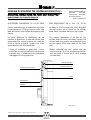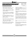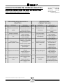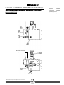
1
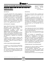
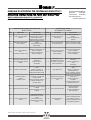
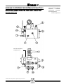
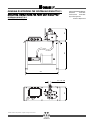
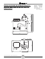
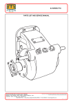
Sistema Qualità Certificato
UNI EN ISO 9001
MANUALE DI ISTRUZIONI PER CENTRALINA MINILIFT 50/S
OPERATING INSTRUCTIONS FOR PUMP UNIT MINILIFT 50/S
D843MITGB
MINILIFT 50/S
MINILIFT 50
Possibili variazioni senza preavviso! · Subject to change without notice!
NUOVO BLOCCO VALVOLA
NEW VALVE BLOCK
MANUALE DI ISTRUZIONI PER CENTRALINA MINILIFT 50/S
OPERATING INSTRUCTIONS FOR PUMP UNIT MINILIFT 50/S
INFORMAZIONI GENERALI
GENERAL INFORMATION
Pagina/page D843MITGB.002
Data/date
01.01.2005
Versione/issue
01.01.2005
Approvato/approved:
Technical Department
DESCRIZIONE
DESCRIPTION
La centralina Minilift 50/S è stata progettata e
costruita rispettando le norme europee EN 81.2.
I componenti idraulici Minilift 50/S sono adatti
per essere usati in impianti con portate modeste.
La 50/S può essere ad una o due velocità con
motore interno monofase o trifase. Questa
centralina è dotata di rubinetto di linea. Mentre
l’attacco da 1/2” come da EN 81.2, la pompa a
mano e il filtro ispezionabile sono opzionali.
The pump unit Minilift 50/S is projected and
constructed by respecting the European standard
EN 81.2.
The hydraulic components Minilift 50/S are
suitable for installations with reduced loads.
The 50/S should have one or two speeds with a
submersed single-phase or three-phase motor.
This pump unit is equipped with a line shut-off
valve. While the 1/2” connection as per EN 81.2.,
the hand pump and the inspectable filter are
optional.
RESPONSABILITA’ E GARANZIA
Questo “Manuale di istruzioni” è parte integrante
dell’impianto e deve essere tenuto in luogo
protetto e accessibile a cura dell’installatore.
L’installazione, la messa in marcia e la
manutenzione dell’impianto devono essere
eseguite soltanto da personale esperto.
OMAR Lift declina ogni responsabilità per danni
causati da uso improprio del materiale, incuria o
inesperienza delle persone preposte al montaggio,
alla regolazione e riparazione dei componenti
idraulici.
La garanzia, inoltre, decade se vengono usati
componenti o parti di ricambio non originali, se
vengono effettuate modifiche e riparazioni non
autorizzate o eseguite da personale inesperto e
non qualificato.
PULIZIA E PRECAUZIONI ANTINQUINAMENTO
Le impurità e lo sporco all’interno dell’impianto
idraulico causano malfunzionamento ed usura
precoce.
Tutte le parti dell’impianto che vengono smontate
per il controllo o la riparazione, come pure i tubi
ed i raccordi, devono essere perfettamente puliti
prima di essere rimontati.
Possibili variazioni senza preavviso! · Subject to change without notice!
LIABILITIES AND GUARANTEES
These “Operating instructions” are an integrating
part of the installation itself and have to be kept
in a safe and accesible place.
The put in place, start up and maintenance of an
installation have to be carried out by trained
staff.
OMAR Lift declines all responsibilities for
damages due to improper use of the material,
carelessness or unexperience of the people
dealing with the installation, the adjustment or
the repair of hydraulic components. Besides the
guarantee is not valid anymore if components or
spare parts different from the original ones are
used or if modifications or repairs are carried out
by non- authorised or non-qualified staff.
CLEANING AND ANTI-POLLUTION MEASURES
Cinders and dirt inside the hydraulic installation
cause bad working and precocious wear.
All the installation components which are
disassembled to be controlled or repaired, as well
as pipes and fittings, have to be perfectly cleaned
before being reassembled.
Possible spilled oil from the circuit during repair
MANUALE DI ISTRUZIONI PER CENTRALINA MINILIFT 50/S
OPERATING INSTRUCTIONS FOR PUMP UNIT MINILIFT 50/S
INFORMAZIONI GENERALI
GENERAL INFORMATION
L’olio eventualmente fuoriuscito dal circuito
durante le operazioni di riparazione non deve
essere disperso nell’ambiente, ma deve essere
prontamente raccolto con stracci o spugne.
TUBAZIONI E COLLEGAMENTI IDRAULICI
Per il collegamento della centralina al cilindro
possono essere usati sia tubi in acciaio trafilati a
freddo, normalizzati e decapati che tubi flessibili
per alta pressione, oppure tubazioni miste.
COLLEGAMENTO ELETTRICO
I collegamenti elettrici devono essere fatti da
personale esperto e qualificato, rispettando le
norme specifiche.
Prima di iniziare qualsiasi lavoro occorre
scollegare la corrente elettrica, aprendo
l’interruttore generale.
COLLEGAMENTO DEL MOTORE MONOFASE
Nel motore monofase il condensatore è già
collegato alla morsettiera che si trova all’interno
della scatola.
Per il corretto collegamento del motore occorre
attenersi allo schema indicato dal costruttore o
allo schema riportato in Fig.1.
Motore / Motor
Pagina/page D843MITGB.003
Data/date
01.01.2005
Versione/issue
01.01.2005
Approvato/approved:
Technical Department
operations has not to be spread in the
environment, but has to be promptly collected
with clothes or sponges.
PIPES AND HYDRAULIC CONNECTIONS
To connect the pump unit to the cylinder it is
possible to use normalised and pickled colddrawn steel hoses, flexible hoses suitable for high
pressures or mixed hoses.
ELECTRICAL CONNECTION
Electrical connection has to be carried out by
qualified
staff,
observing
the
specific
instructions.
Before starting any operation it is mandatory to
switch off the electrical generator.
CONNECTION OF THE SINGLE-PHASE MOTOR
In the single-phase motor the condenser is
already connected to the terminal block which is
placed inside the box. For a proper motor
connection it’s necessary to strictly follow the
scheme provided by the manufacturer or the
scheme reported in Pic. 1.
Morsettiera
Terminal block
Fig.1 / Pic.1
Possibili variazioni senza preavviso! · Subject to change without notice!
MANUALE DI ISTRUZIONI PER CENTRALINA MINILIFT 50/S
OPERATING INSTRUCTIONS FOR PUMP UNIT MINILIFT 50/S
MANUTENZIONE DELL’IMPIANTO IDRAULICO
THE HYDRAULIC INSTALLATION MAINTENANCE
Pagina/page D843MITGB.004
Data/date
01.01.2005
Versione/issue
01.01.2005
Approvato/approved:
Technical Department
COLLEGAMENTO DEL MOTORE TRIFASE
CONNECTION OF THE THREE-PHASE MOTOR
Il motore trifase degli impianti Minilift è di
piccola potenza e viene di solito avviato in modo
diretto. Il collegamento del motore trifase può
essere fatto a seconda dei casi, a stella o a
triangolo. La disposizione delle barrette di
collegamento per i due casi è indicata nella Fig.2.
The Minilift three-phase motor is characterized
by low power and it is normally started in a
direct way. The connection of the three-phase
motor can be a star connection or a delta one,
according to the case. The setting of the
connection bands, in both cases, is reported in
Pic. 2.
Fig.2 / Pic. 2
MANUTENZIONE DELL’IMPIANTO IDRAULICO
THE HYDRAULIC INSTALLATION MAINTENANCE
I componenti idraulici non sono soggetti a forte
usura, sono sicuri e richiedono poca
manutenzione. Per ottenere questi risultati, i
componenti devono essere scelti e dimensionati
correttamente e l’olio deve essere adatto alle
caratteristiche dell’impianto.
Hydraulic components are not subject to a
frequent wear, they are safe and need few
maintenance operations. These results are
reached when the components are chosen and
dimensioned correctly on the basis of the
installation characteristics.
PERDITE INTERNE AL GRUPPO VALVOLE
LOSSES INSIDE THE VALVE GROUP
Per verificare la tenuta delle valvole operare come
segue:
The valve sealing is proved as follows:
* Lasciare raffreddare l’olio fino a temperatura
ambiente
* Chiudere il rubinetto di mandata, avviare il
motore simulando una salita e controllare la
pressione sul manometro
Possibili variazioni senza preavviso! · Subject to change without notice!
* Let the oil cool until the room temperature is
reached
* Close the main shut-off valve, start the motor
simulating an upward travel and check the
pressure value on the manometer.
MANUALE DI ISTRUZIONI PER CENTRALINA MINILIFT 50/S
OPERATING INSTRUCTIONS FOR PUMP UNIT MINILIFT 50/S
Pagina/page D843MITGB.005
Data/date
01.01.2005
Versione/issue
01.01.2005
Approvato/approved:
Technical Department
MANUTENZIONE DELL’IMPIANTO IDRAULICO
THE HYDRAULIC INSTALLATION MAINTENANCE
* Se nella valvola non ci sono perdite, dopo aver
fermato il motore, la pressione si mantiene
costante o scende lentamente solo di qualche
bar in qualche minuto, tendendo a stabilizzarsi.
* Stop the motor, if there are no losses in the
valve, the pressure keeps constant or decreases
slowly only of some bars in a few minutes,
tending to settle.
* Se ci sono perdite la pressione scende
rapidamente e continua a scendere
* If there are losses in the valve, the pressure
decreases rapidly and keeps lowering
* Gli elementi della valvola interessati da eventuali
perdite sono:
* The valve components which can be involved in
possible losses are:
EM: Valvola di emergenza
EVD: Elettrovalvola di discesa
VBP: Valvola di blocco pilotata
PM: Pompa a mano
EM: Manual emergency valve
EVD: Down travel electro-valve
VBP: Piloted rupture valve
PM: Hand pump
SOSTITUZIONE GUARNIZIONE VALVOLA VBP (Fig.3)
REPLACING OF THE VBP VALVE SEAL (Pic.3)
* Per accedere al pistoncino della valvola VBP
occorre togliere il blocchetto emergenza e la
pompa a mano se presente (Fig. 3bis)
* To have access to the VBP piston it is necessary
to remove the emergency block and the hand
pump if available (Pic. 3bis)
*
sfilare
* Remove the VBP spring and unthread the VBP
completely
* Svitare la vite che tiene unite le due parti del
pistoncino, sostituire la guarnizione del VBP
* Unscrew the screw holding the two little piston
parts together, replace the seal of the VBP piston
* Riassemblare il pistoncino stringendo la vite che
tiene insieme le due parti del pistoncino
* Reassemble the little piston, tightening the
screw which holds its two parts together
Togliere la molla del
completamente il VBP
VBP
e
* Position the VBP in the valve block and
reassemble all
Vite/Screw
Rondella/Rove
O-ring
Pistone VBP/VBP Piston
Cappellotto/Cap
Fig.3 / Pic.3
Possibili variazioni senza preavviso! · Subject to change without notice!
Pompa a mano
Hand pump
Blocchetto emergenza
Emergency block
Fig.3bis / Pic.3bis
MANUALE DI ISTRUZIONI PER CENTRALINA MINILIFT 50/S
OPERATING INSTRUCTIONS FOR PUMP UNIT MINILIFT 50/S
MANUTENZIONE DELL’IMPIANTO IDRAULICO
THE HYDRAULIC INSTALLATION MAINTENANCE
Pagina/page D843MITGB.006
Data/date
01.01.2005
Versione/issue
01.01.2005
Approvato/approved:
Technical Department
SOSTITUZIONE GUARNIZIONI CIL. HC-60 PIENO
SEAL REPLACEMENT ON A FULL CYL. HC-60
Come si vede dalla Fig.4 la guarnizione principale,
il raschiapolvere e l’O-Ring si trovano tutte sulla
testa del cilindro che è avvitata direttamente sulla
camicia.
As shown in Pic.4 the main seal, the O-Ring and
the dust scraper are all placed on the cylinder
head, which is screwed directly on the cylinder.
Per poter effettuare la sostituzione del set
completo di guarnizioni, la testa del cilindro deve
essere svitata. Per svitare la testa si può usare una
chiave a settore sfruttando i quattro fori ciechi
appositamente fatti sulla testa stessa.
For a correct replacement of the seal set, the
cylinder head has to be unscrewed. Unscrew the
cylinder head using a sector key and operating on
the four special blind holes made on the head
itself.
* Prima di sostituire le guarnizioni occorre
controllare la superficie dello stelo ed eliminare
eventuali righe o ammaccature che potrebbero
danneggiare le nuove guarnizioni.
* Before replacing the seal, control the rod
surface and get rid of the possible irregularities,
such as scores or bruises which could damage
the new seals.
Raschiatore/Scraper
Testa cilindro/Cylinder head
Guarnizione/Main seal
O-Ring
Camicia/Barrel
Stelo/Rod
Fig.4 / Pic.4
Possibili variazioni senza preavviso! · Subject to change without notice!
MANUALE DI ISTRUZIONI PER CENTRALINA MINILIFT 50/S
OPERATING INSTRUCTIONS FOR PUMP UNIT MINILIFT 50/S
MANUTENZIONE DELL’IMPIANTO IDRAULICO
THE HYDRAULIC INSTALLATION MAINTENANCE
* Portare la cabina a fine corsa in alto.
Disporsi con prudenza a fianco della testata del
cilindro e imbracarsi in modo da non cadere.
* Verificare la superficie dello stelo facendolo
scendere in emergenza, eliminando con tela fine
le eventuali irregolarità.
* Prima che lo stelo rientri completamente
bloccare nella posizione più comoda la cabina e
l’eventuale puleggia con dei fermi e scollegare
lo stelo.
* Pulire la testata del cilindro, svitare la vite n. 3 e
far rientrare completamente lo stelo con la
manovra a mano fino a che il manometro
segnerà la pressione zero.
* Svitare la testa del cilindro e sfilarla dallo stelo
Pagina/page D843MITGB.007
Data/date
01.01.2005
Versione/issue
01.01.2005
Approvato/approved:
Technical Department
* Take the car in upper extra travel and the
cylinder in upper end position.
Carefully take a place near the head and, if
necessary, sling with a rope to be able to work
safely and freely.
* Check the rod surface by making it drop in
emergency; using a fine cloth to eliminate any
ruggedness.
* Before the rod breaks back completely inside
the cylinder, it is necessary to use some stops
to block the car and the pulley in the most
comfortable position and disconnect the rod.
* Clean the cylinder head, unscrew the screw n.3
and make the rod break back inside the cylinder
completely manually by means of the hand
manouvre until the manometer shows pressure
= 0.
* Togliere il vecchio set di guarnizioni e rimontare
quelle nuove facendo attenzione a non
danneggiarle durante il montaggio.
* Unscrew the cylinder head and unthread it from
its rod.
* Riavvitare la testa fino in fondo, rimettere in
funzione l’impianto, spurgando l’eventuale aria
formatasi sulla parte superiore del cilindro.
* Remove the old seal set and replace it with a
new one paying attention not to damage them
during the assembling.
* Screw again the head completely and re-start
the installation; if necessary purge the air from
the upper part of the cylinder.
Possibili variazioni senza preavviso! · Subject to change without notice!
MANUALE DI ISTRUZIONI PER CENTRALINA MINILIFT 50/S
OPERATING INSTRUCTIONS FOR PUMP UNIT MINILIFT 50/S
TABELLA REGOLAZIONI MINILIFT 50/S 1 VELOCITA’
REGULATION TABLE MINILIFT 50/S 1 SPEED
REGULATION TABLE
OF MINILIFT 50/S VALVE
TABELLA REGOLAZIONI DELLA VALVOLA
MINILIFT 50/S
VITE
DESCRIZIONE
REGOLAZIONI
N°1
Taratura valvola pressione
massima
Avvitando aumenta la
pressione massima di taratura
Svitando diminuisce la
pressione massima di taratura
N° 3
Taratura contropressione
stelo ed antiscarrucolamento
funi
Avvitando lo stelo da solo non
scende in emergenza
Svitando lo stelo da solo
scende in emergenza
N° 7
N° 8
N°9
Strozzatore messa in
pressione e partenza in salita
Avvitando si ritarda la messa
in pressione con conseguente
partenza dolce
Svitando si ottiene la messa in
pressione immediata con
partenza rapida
Regolatore velocità di discesa
Svitando aumenta la velocità
di discesa
Avvitando diminuisce la
velocità di discesa
Taratura pressione pompa
a mano
Avvitando aumenta la
pressione taratura pompa
a mano
Svitando diminuisce la
pressione taratura pompa
a mano
Possibili variazioni senza preavviso! · Subject to change without notice!
Pagina/page D843MITGB.008
Data/date
01.01.2005
Versione/issue
01.01.2005
Approvato/approved:
Technical Department
SCREW
DESCRIPTION
REGULATIONS
N 1
Adjusting of the valve
max pressure
Screw to increase max
pressure
Unscrew to decrease max
pressure
N 3
Rod counter-pressure
and rope anti-loosening
device adjusting
Screw not to make the rod
drop in emergency
Unscrew to make the rod
drop in emergency
Choke device for pressure
activation and upward
start
Screw to delay the
pressure activation with a
consequent smooth start
Unscrew to obtain an
immediate pressure
activation with a
consequent quick start
N 8
Down high speed regulator
Unscrew to increase the
downward speed
Screw to decrease the
downward speed
N 9
Hand pump pressure
adjusting
Screw to increase the hand
pump adjusting pressure
Unscrew to decrease the
hand pump adjusting pressure
N7
MANUALE DI ISTRUZIONI PER CENTRALINA MINILIFT 50/S
OPERATING INSTRUCTIONS FOR PUMP UNIT MINILIFT 50/S
VALVOLA MINILIFT 50/S
MINILIFT VALVE 50/S
Blocchetto emergenza
Emergency block
Possibili variazioni senza preavviso! · Subject to change without notice!
Pagina/page D843MITGB.009
Data/date
01.01.2005
Versione/issue
01.01.2005
Approvato/approved:
Technical Department
MANUALE DI ISTRUZIONI PER CENTRALINA MINILIFT 50/S
OPERATING INSTRUCTIONS FOR PUMP UNIT MINILIFT 50/S
TABELLA REGOLAZIONI MINILIFT 50/S 2 VELOCITA’
REGULATION TABLE MINILIFT 50/S 2 SPEEDS
Pagina/page D843MITGB.010
Data/date
01.01.2005
Versione/issue
01.01.2005
Approvato/approved:
Technical Department
REGULATION TABLE
OF MINILIFT 50/S VALVE
TABELLA REGOLAZIONI DELLA VALVOLA
MINILIFT 50/S
SCREW
DESCRIPTION
REGULATIONS
Avvitando aumenta la
pressione massima di taratura
Svitando diminuisce la
pressione massima di taratura
N 1
Adjusting of the valve
max pressure
Screw to increase max
pressure
Unscrew to decrease max
pressure
N° 2
Regolazione bassa velocità
(salita e discesa)
Avvitando aumenta la bassa
velocità
Svitando diminuisce la
bassa velocità
N 2
Upward and downward
low speed regulation
Screw to decrease low speed
Unscrew to increase low speed
N° 3
Taratura contropressione
stelo
ed anstiscarrucolamento funi
Avvitando lo stelo da solo non
scende in emergenza
Svitando lo stelo da solo
scende in emergenza
N3
Rod counter-pressure and
rope anti-loosening
device adjusting
Screw not to make the rod
drop in emergency
Unscrew to make the rod
drop in emergency
N° 5
Strozzatore rallentamento da
alta a bassa velocità (salita e
discesa)
Avvitando frena più
lentamente
Svitando frena più
velocemente
N 5
Choke device for the
deceleration from high to
low speed in upward and
downward directions
Screw to make the car brake
more slowly
Unscrew to make the car
brake
more quickly
Limitatore velocità salita
Avvitando si riduce la velocità
in salita
Svitando si aumenta la
velocità in salita fino alla
massima portata della pompa
High speed limiter
Screw to reduce the upward
speed
Unscrew to increase the
upward speed up to
the max allowed by the pump
Strozzatore messa in
pressione
e partenza in salita
Avvitando si ritarda la messa
in pressione con conseguente
partenza dolce
Svitando si ottiene la messa in
pressione immediata con
partenza rapida
Choke device for pressure
activation and upward
start
Screw to delay the pressure
activation with a consequent
smooth start
Unscrew to obtain an
immediate
pressure activation with a
consequent quick start
N 8
Down high speed regulator
Screw to increase the
downward speed
Unscrew to decrease the
downward speed
N 9
Hand pump pressure
adjusting
Screw to increase the hand
pump adjusting pressure
Unscrew to decrease the hand
pump adjusting pressure
VITE
DESCRIZIONE
REGOLAZIONI
N°1
Taratura valvola pressione
massima
N°6
N° 7
N° 8
N° 9
Avvitando aumenta la velocità
di discesa
Regolatore velocità di discesa
Svitando diminuisce la velocità
di discesa
Taratura pressione pompa
a mano
Avvitando aumenta la
pressione taratura pompa
a mano
Svitando diminuisce la
pressione taratura pompa
a mano
Possibili variazioni senza preavviso! · Subject to change without notice!
N 6
N 7
MANUALE DI ISTRUZIONI PER CENTRALINA MINILIFT 50/S
OPERATING INSTRUCTIONS FOR PUMP UNIT MINILIFT 50/S
VALVOLA MINILIFT 50/S
MINILIFT VALVE 50/S
Blocchetto emergenza
Emergency block
Possibili variazioni senza preavviso! · Subject to change without notice!
Pagina/page D843MITGB.011
Data/date
01.01.2005
Versione/issue
01.01.2005
Approvato/approved:
Technical Department
MANUALE DI ISTRUZIONI PER CENTRALINA MINILIFT 50/S
OPERATING INSTRUCTIONS FOR PUMP UNIT MINILIFT 50/S
Pagina/page D843MITGB.012
Data/date
01.01.2005
Versione/issue
01.01.2005
Approvato/approved:
Technical Department
230
CENTRALINA MINILIFT 50/S
MINILIFT PUMP UNIT 50/S
520
30
550
250
1/2 “- 3/4” Gas
Possibili variazioni senza preavviso! · Subject to change without notice!
MANUALE DI ISTRUZIONI PER CENTRALINA MINILIFT 50/S
OPERATING INSTRUCTIONS FOR PUMP UNIT MINILIFT 50/S
Pagina/pag D843MITGB.013
Data/date
01.01.2005
Versione/issue
01.01.2005
Approvato/approved:
Technical Department
581
229
CENTRALINA MINILIFT 50
MINILIFT PUMP UNIT 50
352
30
500
350
1/2 “- 3/4” Gas
Possibili variazioni senza preavviso! · Subject to change without notice!
MANUALE DI ISTRUZIONI PER CENTRALINA MINILIFT 50/S
OPERATING INSTRUCTIONS FOR PUMP UNIT MINILIFT 50/S
INFORMAZIONI GENERALI
GENERAL INFORMATION
Pagina/page D843MGBIT.014
Data/date
01.01.2005
Versione/issue
01.01.2005
Approvato/approved:
Technical Department
TIPOLOGIA CENTRALINA: MINILIFT V1-V2
V2
PUMP UNIT TYPOLOGY: MINILIFT V1-V
TAB. N°
32.0
REV.0
N.B.: Tolleranza sulla velocità cabina 5%
Allowance on the car speed 5%
RAPPORTI: Ø STELO-VELOCITA'
PRESSIONE STATICA-POTENZA
MOTORE
RATIO: ROD Ø - SPEED
STATIC PRESSURE - MOTOR
POWER
Approvato
R&D
Approved R&D
CILINDRO IN TAGLIA 2:1
INDIRECT SIDE ACTING CYLINDER 2:1
STELO Ø [mm]
Ø ROD [mm]
CENTRALINE-VALVOLE
PUMP UNITS- VALVES
16
POMPA [l/min]
PUMP [l/min]
23
8
12
1,5
1,5
1,5
2,2
1,5
2,2
MOTORE [kW]
MOTOR [ kW]
16
16
16
18
16
18
Assorbimento [A] Monofase
Single-phase Absorption [A]
12/7
12/7
12/7
17/10
12/7
17/10
Assorbimento [A] Trifase
Three-phase Absorption [A]
84
77
56
77
38
56
TARATURA VITE1
sovrappressione [bar]
SCREW1 ADJUSTING
overpressure [bar]
60
55
40
55
27
40
PRESSIONE STATICA MASSIMA [bar]
MAXIMUM STATIC PRESSURE [bar]
60
0,09
0,134
0,18
0,26
70
0,07
0,1
0,14
0,2
80
0,05
0,08
0,11
0,15
CT-2-40*
0,07
0,11
0,15
0,21
VELOCITA' CABINA [m/s]
CAR SPEED [m/s]
* CT-2-40 : Cilindro telescopico a due stadi /Two stages telescopic cylinder
** Nel caso di cilindro diretto, la velocità è metà/In case of direct acting cylinder the speed is half
DIAMETRO STELO
ROD DIAMETER
60 PIENO
60 FULL
60x5
70x5
70x7,5
80x5
80x7,5
CT2-40
CORSA STELO MAX (mm)
MAX ROD TRAVEL (mm)
9,2
7,6
6
4,6
6,3
Capacità Serbatoio
Tank capacity
( Litri / Liters)
Livello minimo olio
Minimum oil level
(Litri / Liters)
Olio utilizzabile
Usable oil
(Litri / Liters)
43
20
23
Possibili variazioni senza preavviso! · Subject to change without notice!
MANUALE DI ISTRUZIONI PER CENTRALINA MINILIFT 50/S
OPERATING INSTRUCTIONS FOR PUMP UNIT MINILIFT 50/S
Pagina/page D843MITGB.015
Data/date
01.01.2005
Versione/issue
01.01.2005
Approvato/approved:
Technical Department
INFORMAZIONI GENERALI
GENERAL INFORMATION
[m]
Pressione statica [bar]
12
11
14
10
CORSA TOTALE DELLO STELO + EVENTUALE PULEGGIA FINO ALL’ASSE
TOTAL ROD STROKE + DISTANCE RODHEAD- PULLEY IF IT EXISTS
CORSA TOTALE DELLO STELO + EVENTUALE PULEGGIA FINO ALL’ASSE
TOTAL ROD STROKE + DISTANCE RODHEAD- PULLEY IF IT EXISTS
10
Pressione statica [bar]
Static pressure [bar]
[m]
Static pressure [bar]
20
9
8
30
7
30
40
6
40
50
5
50
60
60 full
60
4
60X5
3
200
400
600
800
1000
1200
1400
1600
1800
2000
12
10
20
8
HC T2-40 CON GUIDE
WITH GUIDES
30
40
6
45
20
4
30
40
45
HC T2-40 SENZA GUIDE
WITHOUT GUIDES
2
[kg]
600
400
200
800
1000
[kg]
1200
CARICO TOTALE EFFETTIVO SULLO STELO / EFFECTIVE TOTAL LOAD ON THE ROD [KG]
CARICO TOTALE EFFETTIVO SULLO STELO / EFFECTIVE TOTAL LOAD ON THE ROD [KG]
[m]
Pressione statica [bar]
Static pressure [bar]
13
10
12
10
11
10
9
CORSA TOTALE DELLO STELO + EVENTUALE PULEGGIA FINO ALL’ASSE
TOTAL ROD STROKE + DISTANCE RODHEAD- PULLEY IF IT EXISTS
20
8
20
7
30
30
6
40
80X7,5
40
5
50
50
70X7,5
80X5
70X5
4
3
200
400
600
800
1000
1200
1400
1600
1800
2000
2200
2400
2600
[kg]
CARICO TOTALE EFFETTIVO SULLO STELO / EFFECTIVE TOTAL LOAD ON THE ROD [KG]
Possibili variazioni senza preavviso! · Subject to change without notice!
OMAR LIFT S.R.L.
Via F.lli Kennedy 22/D I-24060 Bagnatica (BG) ITALY
Tel. +39 035 689611 Fax +39 035 689671
E-mail: [email protected]
http://www.omarlift.it
Possibili variazioni senza preavviso! · Subject to change without notice!