1
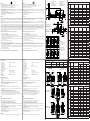
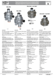
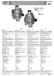
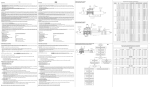
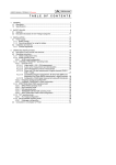
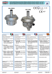
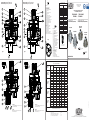
VERSIONE COMPACT (Q=25 m3/h) 2MBC - 2MCC
STANDARD VERSION (Q=100 m3/h) 2MB - 2MCS
Codici e dimensioni molle in mm
Springs code and dimensions in mm
COMPACT VERSION (Q=25 m3/h) 2MBC - 2MCC
fig. 1, 2 e 3
1
2
3
4
5
6
7
8
9
10
11
12
13
14
15
16
17
18
19
20
21
22
23
24
25
26
27
28
29
- Vite di regolazione P2
- Molla di taratura P2
- Molla di taratura sfioro
- Disco superiore per membrana
- Viti di fissaggio
- Corpo
- Organo filtrante (solo su FRG...)
- Otturatore (blocco)
- Fondello
- Tappo di chiusura (blocco)
- Flangia (solo su versioni standard)
- Membrana di compensazione
- Perno centrale (blocco)
- Membrana di funzionamento blocco
- Molla di taratura blocco max
- Regolazione taratura blocco max
- Regolazione taratura blocco min
- Perno di riarmo
- Molla blocco min
- Imbuto
- Perno centrale (regolatore)
- Otturatore (regolatore)
- Presa di pressione
- Membrana di funzionamento
- Tappo antipolvere
- Regolazione sfioro
- Tappo di chiusura (regolatore)
- Chiave speciale per taratura
- Tappo G 1/8” (presa impulso esterna)
(Nm3/h)
Modelli
Models
2MBC - 2MCC
COMPACT
DN 15 - 20 -25
2MB - 2MCS
STANDARD
DN 15
2MB - 2MCS
STANDARD
DN 20
2MB - 2MCS
STANDARD
DN 25
ATTENZIONE:
Le versioni standard 2MCS hanno il fondello piatto e sono senza
blocchi di sicurezza OPSO e UPSO
ATTENZIONE:
Le versioni compact 2MCC hanno il fondello piatto e sono senza
blocchi di sicurezza OPSO e UPSO
1,5x29x46x6
MO-0410
1,5x29x58x7
MO-0440
2,2x29x47x6,5
MO-0520
2,5x29x50x7
MO-1320
3,5x29,8x64x9
MO-1305
3,5x29,8x98x11,5
MO-2550
4X29X98X8
Codici molle OPSO
OPSO spring codes
(d x De x Lo x it)
MO-0650
2x35x20x4
MO-0680
2X35X26X4,5
MO-0780
2,2X35X23,5X3,5
MO-0880
2X35,5X27X3
MO-0890
2,5x35x27x2,25
MO-0990
3x35x33,5x3,5
Codici molle UPSO
UPSO spring codes
(d x De x Lo x it)
MO-0153
0,9x17x45x7
MO-0204
1x17x40x6
MO-0205
1,2x15x36x5
Via Moratello, 5/6/7 - 37045
Z.A.I. Legnago (VR) Italy
www.madas.it
REGOLATORE DI PRESSIONE PER GAS
GAS PRESSURE REGULATOR
FRG-RG/2MCS - FRG-RG/2MCC
FRG/2MB... - FRG/2MBC...
Conforme Direttiva 2009/142/CE (Direttiva Gas)
Conforme EN 88.2 - EN 334
Conforme Direttiva 97/23/CE (Direttiva PED)
Conforme Direttiva 94/9/CE (Direttiva ATEX)
In conformity with the 2009/142/EC Directive (Gas Directive)
In conformity with EN 88.2 - EN 334
In conformity with the 97/23/EC Directive (PED Directive)
In conformity with the 94/9/EC Directive (ATEX Directive)
FRG/2MCS
RG/2MCS
FRG/2MB
(d x De x Lo x it)
Differential relief valve spring codes
- P2 calibration screw
MO-1950
0,9x11x5x20,5x8
- P2 setting spring
- Relief valve setting spring
MO-2155
2x17x29x6
- Diaphragm upper disc
- Fixing screws
- Body
- Filtering organ (only on FRG...)
- Obturator (shut off)
- Bottom
- Closing cap (shut off)
- Flange (only on standard version)
- Compensation diaphragm
- Central pin (shut off)
- Working shut off diaphragm
- Max shut off setting spring
- Max shut off calibration
it= numero di spire totali
- Min shut off calibration
it= total number of turns
- Reset pin
- Min shut off setting spring
- Funnel
- Central pin (regulator)
- Obturator (regulator)
- Pressure nipple
- Working diaphragm
- Antidust cap
- Relief calibration
- Closing cap (regulator)
- Special key for setting
- G 1/8” cap (esternal pulse connection)
PORTATE REGOLATORI /
28
MO-0403
Codici molle differenziale sfioro
1
2
3
4
5
6
7
8
9
10
11
12
13
14
15
16
17
18
19
20
21
22
23
24
25
26
27
28
29
fig. 2
28
(d x De x Lo x it)
fig. 1, 2 and 3
fig. 3
fig. 1
Codici molle regolazione P2
P2 regulation spring codes
FRG/2MBC
FRG/2MCC
RG/2MCC
II 2G - II 2D
MADAS-03
0497
MADE IN ITALY
CAPACITIES OF REGULATORS
Gas naturale - Natural Gas
Pressione di ingresso - Inlet Pressure
P2 (mbar)
0,5 bar
1 bar
2 bar
3-4
bar
5 bar
20
25
25
25
25
25
30
25
25
25
25
25
50
25
25
25
25
25
100
25
25
25
25
25
200
25
25
25
25
25
20
25
27
30
30
37
39
30
37
37
37
39
50
50
50
50
50
50
100
60
62
62
62
62
200
85
85
85
85
85
300
70
100
100
100
100
20
42
42
50
50
50
55
55
30
50
50
55
50
70
70
70
70
70
100
100
100
100
100
100
200
86
100
100
100
100
300
86
100
100
100
100
100
100
100
100
20
100
30
100
100
100
100
100
50
100
100
100
100
100
100
100
100
100
100
100
200
100
100
100
100
100
300
100
100
100
100
100
Mod. MADAS IT/100.04
VERSIONE STANDARD (Q=100 m3/h) 2MB - 2MCS
Dati ricavati SENZA L'UTILIZZO del tubetto sensore esterno
Data obtained WITHOUT USING of external sensor tube
WARNING:
2MCS standard versions have the plain bottom and don’t have
OPSO and UPSO safety shut off
WARNING:
2MCC compact versions have the plain bottom and don’t have
OPSO and UPSO safety shut off
Aria - Air - Air - Aire Gas naturale - Natural Gas - Gaz naturel - Gas natural
Gas di città - Town gas - Gaz de ville - Gas de ciudad
GPL - LPG - Gaz de pétrole liquéfié - Gas líquido
=
=
=
=
0,806
1
1.177
0.62
Via Moratello, 5/6/7 - 37045 Z.A.I. Legnago (VR) Italy
Tel. +39 0442/23289 - Fax +39 0442/27821 - http://www.madas.it - e-mail: [email protected]
Possono essere dotati dei seguenti dispositivi di sicurezza e accessori a seconda delle esigenze dell’impianto:
It can be equipped with the following safety devices and accessory:
• dispositivo di blocco per sovrappressione a valle (solo FRG/2MB - FRG/2MBC): interrompe l’erogazione quando la pressione in uscita del regolatore supera
il valore di taratura del dispositivo
• outlet over pressure shut off device (only FRG/2MB - FRG/2MBC): it stops the gas flow when the regulator outlet pressure goes up the device setting
value
• valvola di sfioro: scarica all’esterno piccole portate di gas nel caso si verifichino sovrappressioni a valle del regolatore. Tale scarico è convogliabile all’asterno nel
caso di installazioni in ambienti con scarsa ventilazione
• relief valve: it vents outside small quantity of gas in case there are downstream regulator overpressure. That exhaust it is convoyed outside in case of installation
in environment with bad ventilation
• dispositivo di blocco di minima pressione a valle (solo FRG/2MB - FRG/2MBC): interrompe l’erogazione quando la pressione in uscita del regolatore scende
al di sotto del valore di taratura del dispositivo. Interviene anche in caso di mancanza di alimentazione a monte
• outlet low pressure shut off device (only FRG/2MB - FRG/2MBC): it stops the gas flow when the regulator outlet pressure goes down the device setting
value. It closes even if there is no inlet pressure.
• presa di pressione in uscita.
• outlet pressure test point.
INSTALLAZIONE
INSTALLATION
Il regolatore è conforme alla Direttiva 94/9/CE (denominata Direttiva ATEX 100 a) come apparecchio del gruppo II, categoria 2G e come apparecchio del gruppo II,
categoria 2D; come tale è idoneo per essere installato nelle zone 1 e 21 (oltre che nelle zone 2 e 22) come classificate nell’allegato I alla Direttiva 99/92/CE. Il regolatore
non è idoneo per l’utilizzo nelle zone 0 e 20 come definite nella già citata Direttiva 99/92/CE. Per determinare la qualifica e l’estensione delle zone pericolose si veda la
norma EN 60079-10.
L’ apparecchio, se installato e sottoposto a manutenzione nel pieno rispetto di tutte le condizioni e istruzioni tecniche riportate nel presente documento, non costituisce
fonte di pericoli specifici: in particolare, in condizioni di normale funzionamento, è prevista, da parte del regolatore, l’emissione in atmosfera di sostanza infiammabile
solo occasionalmente.
The regulator is in conformity with the Directive 94/9/CE (said Directive ATEX 100 a) as device of group II, category 2G and as device of group II, category 2D; for this
reason it is suitable to be installed in the zones 1 and 21 (besides in the zones 2 and 22) as classified in the attachment I to the Directive 99/92/EC. The regulator is
not suitable to be used in zones 0 and 20 as classified in the already said Directive 99/92/EC.
Scarico in aria libera
Free air exhaust
manometro bassa pressione
low pressure gauge
rete - pipe
utenza - user
To determine the qualification and the extension of the dangerous zones, see the norm EN 60079-10. The device, if installed and serviced respecting all the conditions
and the technical instructions of this document, is not source of specific dangers: in particular, during the normal working, is forecast, by the regulator, the emission in
the atmosphere of inflammable substance only occasionally.
Il regolatore può essere pericoloso rispetto alla presenza nelle sue vicinanze di altre apparecchiature in caso di intervento della valvola di sfioro integrata o in caso di
rottura della membrana di funzionamento (24). In quest’ultimo caso (e solo in questo) il regolatore costituisce una sorgente di emissione di atmosfera esplosiva di grado
continuo e, come tale, può originare zone pericolose 0 come definite nella Direttiva 99/92/CE. In condizioni di installazione particolarmente critica (luoghi non presidiati,
carenza di manutenzione, scarsa disponibilità di ventilazione) e, soprattutto in presenza nelle vicinanze del regolatore di potenziali fonti di innesco e/o apparecchiature
pericolose nel funzionamento ordinario in quanto suscettibili di originare archi elettrici o scintille, è necessario valutare preliminarmente la compatibilità fra il regolatore
e tali apparecchiature. In ogni caso è necessario prendere ogni precauzione utile ad evitare che il regolatore sia origine di zone 0: ad esempio verifica periodica annuale
di regolare funzionamento, possibilità di modificare il grado di emissione della sorgente o di intervenire sullo scarico all’esterno della sostanza esplosiva canalizzando ad
esempio all’esterno lo scarico della valvola si sfioro.
The regulator can be dangerous as regards to the presence close to it of other devices when the integrated relief valve vents or in case of damage of the working
diaphragm (24). Only in this last case the regulator is a source of emission of the continue degree explosive atmosphere and, so, it can originate dangerous areas 0 as
defined in the 99/92/EC Directive. In conditions of particularly critic installation (places not protected, lack of servicing, lacking availability of ventilation) and, especially
in presence, close to the regulator, of potential sources of primer and/or dangerous devices during the normal working because susceptible to origine electric arcs or
sparks, it is necessary to value before the compatibility between the regulator and these devices.In any case it is necessary to take any useful precaution to avoid that
the regulator could be origin of areas 0: for example yearly periodical inspection of regular working, possibility to change the emission degree of the source or to attend
on the exhaust outside the explosive material canalizing outside, for example, the relief valve discharge
ATTENZIONE: le operazioni di installazione/manutenzione devono essere eseguite da personale qualificato.
WARNING: all installation/maintenance work must be carried out by skilled staff.
• E’ necessario chiudere il gas prima dell’installazione.
• The gas supply must be shut off before installation.
• Verificare che la pressione di linea NON SIA SUPERIORE alla pressione massima dichiarata sull’etichetta del prodotto.
• Check that the line pressure DOES NOT EXCEED the maximum pressure stated on the product label.
• Il regolatore è normalmente posizionato prima dell’utenza. Deve essere installato con la freccia in rilievo sul corpo (6) rivolta verso l’utenza.
• The regulator is normally installed before the user. It must be installed with the arrow on the body (6) towards the user.
Attacchi
Connections
DN 15
( Rp 1/2”)
Closing gas pressure filterregulator (FRG/2MBC - FRG/2MB - FCS - FCC) or regulator (RCS - RCC).
These pressure regulators are used both in domestic and industrial users that use natural gas, LPG or other not corrosive gases (dry gases).
FRG/2MBC - FCC - RCC versions (COMPACT versions) are preferable for small users (up to 25 m3/h).
Caratteristiche molle di regolazione - Regulation springs data
DN 20
(Rp 3/4”)
Filtroregolatore (FRG/2MBC - FRG/2MB - FCS - FCC) o regolatore (RCS - RCC) di pressione a chiusura per gas.
Questi regolatori sono impiegati sia nelle installazioni civili che industriali che utilizzano Gas naturale, GPL o altri gas non corrosivi (gas secchi).
Le versioni FRG/2MBC - FCC - RCC (versioni COMPACT) sono preferibili per le piccole utenze (fino a 25 m3/h).
1. SM series jerk handle ON/OFF valve
2. MVB/1 MAX over pressure shut off valve
3. FM series gas filter
4. RG/2MCC o RG/2MCS series pressure regulator
5. Ball valve downstream of regulator
6. Lever for remote SM ON/OFF valve control
DN 25
( Rp 1”)
DESCRIPTION
EXAMPLE OF INSTALLATION (2MCC - 2MCS )
1. Valvola a strappo SM
2. Valvola di blocco MVB/1 MAX di massima pressione
3. Filtro gas serie FM
4. Regolatore gas serie RG/2MCC o RG/2MCS
5. Valvola a sfera a valle del regolatore
6. Leva comando a distanza valvola a strappo SM
ESEMPIO DI INSTALLAZIONE (2MBC - 2MB )
Scarico in aria libera
Free air exhaust
1. Valvola a sfera a monte
2. Filtroregolatore FRG/2MBC o FRG/2MB
3. Valvola a sfera a valle del regolatore
manometro bassa pressione
low pressure gauge
manometro alta pressione
high pressure gauge
P2 (mbar)
10 ÷ 25 (MO-0403)
Attacchi
Connections
campo OPSO
OPSO range
campo UPSO
UPSO range
campo differenziale sfioro
differential relief valve range
(mbar)
(mbar)
(mbar)
20 ÷ 70 (MO-0650)
10 ÷ 30 (MO-0153)
10 ÷ 60
(MO-1950)
FBC02Z
110
rete - pipe
utenza - user
codice
code
25 ÷ 35 (MO-0410)
40 ÷ 90 (MO-0680)
10 ÷ 30 (MO-0153)
10 ÷ 60
(MO-1950)
FBC02Z
120
35 ÷ 120 (MO-0440)
50 ÷ 180 (MO-0780)
20 ÷ 50 (MO-0204)
10 ÷ 60
(MO-1950)
FBC02Z
130
110 ÷ 200 (MO-0520)
120 ÷ 260 (MO-0880)
50 ÷ 110 (MO-0205)
10 ÷ 60
(MO-1950)
FBC02Z
140
10 ÷ 25 (MO-0403)
20 ÷ 70 (MO-0650)
10 ÷ 30 (MO-0153)
10 ÷ 60
(MO-1950)
FBC03Z
110
25 ÷ 35 (MO-0410)
40 ÷ 90 (MO-0680)
10 ÷ 30 (MO-0153)
10 ÷ 60
(MO-1950)
FBC03Z
120
35 ÷ 120 (MO-0440)
50 ÷ 180 (MO-0780)
20 ÷ 50 (MO-0204)
10 ÷ 60
(MO-1950)
FBC03Z
130
110 ÷ 200 (MO-0520)
120 ÷ 260 (MO-0880)
50 ÷ 110 (MO-0205)
10 ÷ 60
(MO-1950)
FBC03Z
140
10 ÷ 25 (MO-0403)
20 ÷ 70 (MO-0650)
10 ÷ 30 (MO-0153)
10 ÷ 60
(MO-1950)
FBC04Z
110
25 ÷ 35 (MO-0410)
40 ÷ 90 (MO-0680)
10 ÷ 30 (MO-0153)
10 ÷ 60
(MO-1950)
FBC04Z
120
35 ÷ 120 (MO-0440)
50 ÷ 180 (MO-0780)
20 ÷ 50 (MO-0204)
10 ÷ 60
(MO-1950)
FBC04Z
130
110 ÷ 200 (MO-0520)
120 ÷ 260 (MO-0880)
50 ÷ 110 (MO-0205)
10 ÷ 60
(MO-1950)
FBC04Z
140
P2 (mbar)
(FRG/2MBZ - R - F - M)
campo OPSO
OPSO range
campo UPSO
UPSO range
campo differenziale sfioro
differential relief valve range
(mbar)
(mbar)
(mbar)
EXAMPLE OF INSTALLATION (2MBC - 2MB )
1. Upstream ball valve
2. FRG/2MBC o FRG/2MB filter regulator
3. Ball valve downstream of regulator
(FRG/2MBCZ - R - F - M)
Caratteristiche molle di regolazione - Regulation springs data
DN 15
( Rp 1/2”)
DESCRIZIONE
ESEMPIO DI INSTALLAZIONE (2MCC - 2MCS )
codice
code
20 ÷ 30 (MO-0410)
40 ÷ 90 (MO-0680)
10 ÷ 30 (MO-0153)
10 ÷ 60
(MO-1950)
FB02Z
110
30 ÷ 90 (MO-0440)
50 ÷ 180 (MO-0780)
20 ÷ 50 (MO-0204)
10 ÷ 60
(MO-1950)
FB02Z
120
90 ÷ 170 (MO-0520)
120 ÷ 160 (MO-0880)
50 ÷ 110 (MO-0205)
10 ÷ 60
(MO-1950)
FB02Z
130
170 ÷ 400* (MO-1320)
200 ÷ 550 (MO-0890)
50 ÷ 110 (MO-0205)
40 ÷ 200
(MO-2155)
FB02Z
140
300 ÷ 650* (MO-1305)
500 ÷ 1000 (MO-0990)
50 ÷ 110 (MO-0205)
40 ÷ 200
(MO-2155)
FB02Z
150
600 ÷ 900* (MO-2550)
500 ÷ 1000 (MO-0990)
50 ÷ 110 (MO-0205)
40 ÷ 200
(MO-2155)
FB02Z
160
• It can be installed in any position but it is preferable the installation with the spring (2) in vertical position (see fig. 1 and 2). Outside the regulator and downstream
of it there is a checking pressure-tap (23) for the control of the regulation pressure.
• Si consiglia di collegare la presa di impulso con attacco G 1/8” a valle del regolatore (vedi esempio di installazione) se la portata di gas supera i 40 Nm3/h. Per farlo
è necessario rimuovere il tappo (29).
• We suggest to connect the G 1/8” connection pulse tap to downstream regulator pipe (please see installation example) if the gas flow goes up 40 Nm3/h. It is
necessary to remove the tap (29) to do it.
20 ÷ 30 (MO-0410)
40 ÷ 90 (MO-0680)
10 ÷ 30 (MO-0153)
10 ÷ 60
(MO-1950)
FB03Z
110
• Canalizzare all’esterno lo scarico della valvola di sfioro (vedi esempio di installazione).
• Canalize outside the relief valve discharge (please see installation example).
30 ÷ 90 (MO-0440)
50 ÷ 180 (MO-0780)
20 ÷ 50 (MO-0204)
10 ÷ 60
(MO-1950)
FB03Z
120
• Durante l’installazione evitare che detriti o residui metallici penetrino all’interno dell’apparecchio.
• During installation take care not to allow debris or scraps of metal to enter the device.
• Se l’ apparecchio è filettato verificare che la lunghezza del filetto della tubazione non sia eccessiva per non danneggiare il corpo (6) dell’apparecchio in fase di
avvitamento. Non usare il contenitore della molla come leva per l’avvitamento ma servirsi dell’apposito utensile. Assemblare l’apparecchio sull’impianto con tubi e/o
raccordi le cui filettature siano coerenti con la connessione da assemblare.
• If the device is threaded check that the pipeline thread is not too long; overlong threads may damage the body (6) of the device when screwed into place. Do
not use the spring casing for leverage when screwing into place; use the appropriate tool. Assemble pipe and fittings which are consistent with device connection
threads.
• Se l’apparecchio è flangiato verificare che le controflange di ingresso e uscita siano perfettamente parallele per evitare di sottoporre il corpo (6) a inutili sforzi
meccanici, calcolare inoltre lo spazio per l’inserimento della guarnizione di tenuta. Se a guarnizioni inserite lo spazio rimanente è eccessivo non cercare di colmarlo
stringendo eccessivamente i bulloni dell’apparecchio.
• If the device is flanged check that the inlet and outlet counterflanges are perfectly parallel to avoid unnecessary mechanical stresses on the body (6) of the device.
Also calculate the space needed to fit the seal. If the gap left after the seal is fitted is too wide, do not try to close it by over-tightening the device’s bolts.
• In ogni caso dopo l’installazione verificare la tenuta dell’impianto.
• Always check that the system is gas-tight after installation.
Examples 1” connections
Substitute the letter “Z” of the
codes indicated in the table with the
corresponding letter you need.
WARNING: all installation/wiring/maintenance work must be carried out by skilled staff.
DN 25
( Rp 1”)
ATTENZIONE: le operazioni di installazione/manutenzione devono essere eseguite da personale qualificato.
Esempi attacchi 1”
Sostituire la lettera “Z” dei codici
indicati in tabella con la lettera
corrispondente alla versione voluta.
DN 20
(Rp 3/4”)
• Può essere installato in qualsiasi posizione anche se è preferibile l’installazione con la molla (2) in verticale (come in fig. 1 e 2). All’esterno del regolatore, a valle dello
stesso è sistemata una presa di pressione (23) per il controllo della pressione di regolazione.
90 ÷ 170 (MO-0520)
120 ÷ 160 (MO-0880)
50 ÷ 110 (MO-0205)
10 ÷ 60
(MO-1950)
FB03Z
130
170 ÷ 400* (MO-1320)
200 ÷ 550 (MO-0890)
50 ÷ 110 (MO-0205)
40 ÷ 200
(MO-2155)
FB03Z
140
300 ÷ 650* (MO-1305)
500 ÷ 1000 (MO-0990)
50 ÷ 110 (MO-0205)
40 ÷ 200
(MO-2155)
FB03Z
150
600 ÷ 900* (MO-2550)
500 ÷ 1000 (MO-0990)
50 ÷ 110 (MO-0205)
40 ÷ 200
(MO-2155)
FB03Z
160
20 ÷ 30 (MO-0410)
40 ÷ 90 (MO-0680)
10 ÷ 30 (MO-0153)
10 ÷ 60
(MO-1950)
FB04Z
110
30 ÷ 90 (MO-0440)
50 ÷ 180 (MO-0780)
20 ÷ 50 (MO-0204)
10 ÷ 60
(MO-1950)
FB04Z
120
90 ÷ 170 (MO-0520)
120 ÷ 160 (MO-0880)
50 ÷ 110 (MO-0205)
10 ÷ 60
(MO-1950)
FB04Z
130
170 ÷ 400* (MO-1320)
200 ÷ 550 (MO-0890)
50 ÷ 110 (MO-0205)
40 ÷ 200
(MO-2155)
FB04Z
140
300 ÷ 650* (MO-1305)
500 ÷ 1000 (MO-0990)
50 ÷ 110 (MO-0205)
40 ÷ 200
(MO-2155)
FB04Z
150
600 ÷ 900* (MO-2550)
500 ÷ 1000 (MO-0990)
50 ÷ 110 (MO-0205)
40 ÷ 200
(MO-2155)
FB04Z
160
* Con membrana rinforzata = With reinforced diaphragm
Use
Environment temperature
Max. superficial temperature
Minimum operating pressure
Maximum operating pressure
Maximum operating pressure
Shut off closing time
P2 accuracy class (AC)
Overpressure lockout accuracy group (AG)
Closing pressure class (SG)
Relief valve
Vent connection
Mechanical strength
Safety factor
Filtering
Filtering class
Threaded connections Rp
On request NPT threaded connections
:
:
:
:
:
:
:
:
:
:
:
:
:
:
:
:
:
Not aggressive gases of the three families (dry gases)
-20 ÷ +60 °C
60 °C
500 mbar
2MBC - 2MB
5 bar
2MCC - 2MCS
3 o 5 bar (see product label)
<1s
10
10
30
tested according to EN 334
G 1/4”
Group 2 (according to EN 13611:2007)
f=4 (5*4 = 20 bar) according to EN 88-2 point 7.2
50 µm
G 2 according to EN 779
(DN 15 - DN 20 - DN 25) according to EN 10226
RIARMO MANUALE (solo FRG/2MBZ - R - F - M):
MANUAL RESET (only FRG/2MBZ - R - F - M):
1. Chiudere il rubinetto o valvola a sfera a valle del regolatore
2. Svitare il tappo (10)
3. Premere leggermente il perno di riarmo (18), attendere qualche istante che si verifichi l’equilibrio di pressione e successivamente premere fino a fine corsa il perno
di riarmo (18).
4. Tenendo premuto il perno di riarmo (18), aprire lentamente il rubinetto a valle del regolatore
5. Rilasciare il perno di riarmo (18), e tirarlo lentamente verso il basso per evitare che sia a contatto con il perno centrale (13)
6. Successivamente riavvitare il tappo (10) nella posizione iniziale.
1. Close the tap or ball valve downstream the regulator.
2. Unscrew the tap (10)
3. Slightly push the reset pin (18), wait a few moments to get the pressure balanced and then push till the end the reset pin (18).
4. Keeping pushed the reset pin (18), slowly open the tap upstream the regulator.
5. Release the reset pin (18), and slowly pull it down in order to avoid any contact with the central pin (13).
6. Subsequently screw again the cap (10) on its original position.
TARATURA (vedere esempio)
SETTING (see the example)
Generalmente gli apparecchi sono pretarati su specifiche del cliente, nel caso sia necessario effettuare la taratura, con l’impianto in portata, occorre:
Normally the devices are presetted according to the customer specification, where it is needed to set it, with the plant giving flow, you need:
• Get a commercial 8 mm spanner* (commercial one) and a proper pressure gauge to check the regulator pressure.
• Unscrew the caps (10) and (27)
• In order to change the setting value of the out let pressure P2, act on the regulation screw (1).
• Screw till the end the setting screws (16) and (26) and place at minimum, unscrewing it, the regulation screw (17).
• To modify the setting value of the minimum pressure shut off tripping, act with the supplied key (28) on the regulation screw (17).
• To modify the setting value of overpressure shut off tripping, act with the supplied screw (28) on the regulation screw (16).
• To modify the setting of the relief valve, act with a 8 mm spanner (not supplied) on the regulation screw (26).
*the commercial key has to be an hex with a pipe type of 8 mm and a maximum external Ø not over than 12 mm.
•
•
•
•
•
•
•
Munirsi di una chiave esagonale* a tubo da 8 mm (chiave commerciale) e di un adeguato manometro per il controllo della pressione a valle del regolatore.
Svitare i tappi (10) e (27).
Per modificare il valore di taratura della pressione di uscita P2 agire sulla vite di regolazione (1).
Avvitare fino a fine corsa le viti di regolazione (16) e (26) e posizionare al minimo, svitandola, la vite di regolazione (17).
Per modificare il valore di taratura di intervento del blocco di minima pressione agire con la chiave in dotazione (28) sulla vite di regolazione (17).
Per modificare il valore di taratura di intervento del blocco di sovrapressione agire con la chiave in dotazione (28) sulla vite di regolazione (16).
Per modificare il valore di taratura di intervento dello sfioro si deve agire con una chiave a tubo commerciale da 8 mm (non fornita) sulla vite di regolazione (26).
* la chiave commerciale deve essere una chiave esagonale a tubo da 8 mm con Ø est. max non superiore a 12 mm.
ESEMPIO
EXAMPLE
Pressione necessaria di regolazione P2=22 mbar - Intervento blocco min UPSO=10 mbar
Intervento blocco max OPSO=40 mbar - Intervento valvola di sfioro 30 mbar
Regulation pressure needed P2 = 22 mbar - Minimum shut off intervention UPSO = 10 mbar
Maximum shut off intervention OPSO = 40 mbar - Relief valve intervention = 30 mbar
•
•
•
•
•
•
•
•
•
•
•
•
•
•
•
•
•
Riarmare il dispositivo di blocco seguendo le istruzioni indicate dal punto 1 al 5 del paragrafo “RIARMO MANUALE”.
Portare, svitando la vite di regolazione (1), la pressione P2, leggendola sul manometro, a 10 mbar.
Avvitare la vite di regolazione (17) fino all’intervento del blocco di minima (UPSO) che a questo punto è tarato a 10 mbar.
Riarmare il dispositivo di blocco seguendo le istruzioni indicate dal punto 1 al 5 del paragrafo “RIARMO MANUALE”.
Premendo con la chiave a tubo da 8 mm sul dado di regolazione (26), aumentare la pressione P2, leggendola sul manometro, fino al valore di taratura OPSO voluto
(arrivare in questo caso a 40 mbar).
Contemporaneamente svitare lentamente la vite di regolazione (16) fino all’intervento del dispositivo di blocco di massima pressione. Avvitare la vite (16) di ¼ di
giro. A questo punto il blocco OPSO è tarato a 40 mbar.
Riarmare il dispositivo di blocco seguendo le istruzioni indicate dal punto 1 al 5 del paragrafo “RIARMO MANUALE”.
Chiudere lentamente il rubinetto a valle del regolatore
Premendo con la chiave a tubo da 8 mm sul dado di regolazione (26), aumentare la pressione P2, leggendola sul manometro, fino al valore di taratura di sfioro
voluto (arrivare in questo caso a 30 mbar).
Senza premere, svitare lentamente la vite di regolazione (26) finche la pressione P2, visualizzata sul manometro, inizia a diminuire.
Lo sfioro è in questo caso tarato a 30 mbar.
Rimuovere la chiave a tubo e richiudere i tappi (10) e (27).
•
•
•
•
•
•
•
Reset the shut off device following the instructions stated from point 1 to point 5 of the paragraph “MANUAL RESET”.
Take, unscrewing the regulation screw (1), the pressure P2, reading on the pressure gauge, to 10 mbar.
Screw the regulation screw (17) till the minimum shut off (UPSO) tripping, which, now is setted to 10 mbar.
Reset the shut off device following the instructions stated from point 1 to point 5 of the paragraph “MANUAL RESET”.
Push with the 8 mm spanner on the regulation nut (26), increasing the P2 pressure, reading on the pressure gauge, till the needed setting value OPSO (in this specific
case to 40 mbar).
In the meanwhile slowly unscrew the regulation screw (16) till the maximum pressure shut off device tripping. Screw the screw (16) ¼ turn. At this point the shut off
OPSO is setted to 40 mbar.
Reset the shut off device following the instructions stated from point 1 to point 5 of the paragraph “MANUAL RESET”.
Slowly close the tap downstream the regulator.
Pushing with the 8 mm spanner on the regulation nut (26), increase the P2 pressure, reading on the pressure gauge, till the needed relief setting value (in this case
to 30 mbar).
Without pushing, slowly unscrew the regulation screw (26) till the P2 pressure, showed on the pressure gauge, starts to decrease.
The relief, in this case, is setted at 30 mbar.
Remove the spanner and close the caps (10) and (27).
MANUTENZIONE
SERVICING
Per eventuali problemi o informazioni relativi alle operazioni di installazione/manutenzione vedere indirizzo e recapiti telefonici riportati in ultima pagina.
For any problems or information concerning installation/maintenance operations, see address and telephone numbers on the back page.
Versioni compact (2MCC)
Compact versions (2MCC)
Versioni standard (2MCS)
Standard versions (2MCS)
A
DN 15 - DN 20 - DN 25
-
120
147
94
-
DN 15 - DN 20 - DN 25
120
147
140
Versioni compact (2MCC)
Compact versions (2MCC)
B
Versioni standard (2MCS)
Standard versions (2MCS)
C
Attacchi
Connections
DN 15
( Rp 1/2”)
•
•
•
•
•
•
•
•
•
•
•
•
•
•
•
•
•
•
DN 20
(Rp 3/4”)
Gas non aggressivi delle 3 famiglie (gas secchi)
-20 ÷ +60 °C
60 °C
500 mbar
2MBC - 2MB
5 bar
2MCC - 2MCS
3 o 5 bar (vedi etichetta prodotto)
<1s
10
10
30
testata secondo indicazioni riportate su EN 334
G 1/4”
Gruppo 2 (secondo EN 13611:2007)
f=4 (5*4 = 20 bar) secondo EN 88-2 punto 7.2
50 µm
G 2 (secondo EN 779)
(DN 15 - DN 20 - DN 25) secondo EN 10226
DN 25
( Rp 1”)
:
:
:
:
:
:
:
:
:
:
:
:
:
:
:
:
:
(mbar)
Attacchi
Connections
Versioni compact (2MBC)
Compact versions (2MBC)
Versioni standard (2MB)
Standard versions (2MB)
(FRG-RG/2MCC)
codice filtroregolatore
code filterregulator
campo differenziale sfioro
differential relief valve range
P2 (mbar)
P. max 0,5 ÷ 3 bar
codice regolatore
code regulator
P. max 0,5 ÷ 5 bar
P. max 0,5 ÷ 3 bar
P. max 0,5 ÷ 5 bar
10 ÷ 25 (MO-0403)
10 ÷ 60
(MO-1950)
FCC02
110
FCC020000
110
RCC02
110
RCC020000
110
25 ÷ 35 (MO-0410)
10 ÷ 60
(MO-1950)
FCC02
120
FCC020000
120
RCC02
120
RCC020000
120
35 ÷ 120 (MO-0440)
10 ÷ 60
(MO-1950)
FCC02
130
FCC020000
130
RCC02
130
RCC020000
130
110 ÷ 200 (MO-0520)
10 ÷ 60
(MO-1950)
FCC02
140
FCC020000
140
RCC02
140
RCC020000
140
10 ÷ 25 (MO-0403)
10 ÷ 60
(MO-1950)
FCC03
110
FCC030000
110
RCC03
110
RCC030000
110
25 ÷ 35 (MO-0410)
10 ÷ 60
(MO-1950)
FCC03
120
FCC030000
120
RCC03
120
RCC030000
120
35 ÷ 120 (MO-0440)
10 ÷ 60
(MO-1950)
FCC03
130
FCC030000
130
RCC03
130
RCC030000
130
110 ÷ 200 (MO-0520)
10 ÷ 60
(MO-1950)
FCC03
140
FCC030000
140
RCC03
140
RCC030000
140
10 ÷ 25 (MO-0403)
10 ÷ 60
(MO-1950)
FCC04
110
FCC040000
110
RCC04
110
RCC040000
110
25 ÷ 35 (MO-0410)
10 ÷ 60
(MO-1950)
FCC04
120
FCC040000
120
RCC04
120
RCC040000
120
35 ÷ 120 (MO-0440)
10 ÷ 60
(MO-1950)
FCC04
130
FCC040000
130
RCC04
130
RCC040000
130
110 ÷ 200 (MO-0520)
10 ÷ 60
(MO-1950)
FCC04
140
FCC040000
140
RCC04
140
RCC040000
140
Caratteristiche molle di regolazione - Regulation springs data
DN 15
( Rp 1/2”)
Impiego
Temperatura ambiente
Temperatura superficiale max
Pressione minima di funzionamento
Pressione max di esercizio
Pressione max di esercizio
Tempo di chiusura blocco
Classe accuratezza P2 (AC)
Gruppo accuratezza blocco sovrapressione (AG)
Classe pressione di chiusura (SG)
Valvola di sfioro
Connessione dello sfiato
Resistenza meccanica
Fattore di sicurezza
Filtraggio
Classe di filtrazione
Attacchi filettati Rp
Su richiesta attacchi filettati NPT
Caratteristiche molle di regolazione - Regulation springs data
DN 20
(Rp 3/4”)
•
•
•
•
•
•
•
•
•
•
•
•
•
•
•
•
•
•
Dimensioni di ingombro in mm - Overall dimensions in mm
TECHNICAL DATA
DN 25
( Rp 1”)
CARATTERISTICHE TECNICHE
P2 (mbar)
codice filtroregolatore
code filterregulator
campo differenziale sfioro
differential relief valve range
(mbar)
(FRG-RG/2MCS)
P. max 0,5 ÷ 3 bar
codice regolatore
code regulator
P. max 0,5 ÷ 5 bar
P. max 0,5 ÷ 3 bar
P. max 0,5 ÷ 5 bar
20 ÷ 30 (MO-0410)
10 ÷ 60
(MO-1950)
FCS02
110
FCS020000
110
RCS02
110
RCS020000
110
30 ÷ 90 (MO-0440)
10 ÷ 60
(MO-1950)
FCS02
120
FCS020000
120
RCS02
120
RCS020000
120
130
90 ÷ 170 (MO-0520)
10 ÷ 60
(MO-1950)
FCS02
130
FCS020000
130
RCS02
130
RCS020000
170 ÷ 400* (MO-1320)
40 ÷ 200
(MO-2155)
FCS02
140
FCS020000
140
RCS02
140
RCS020000
140
300 ÷ 650* (MO-1305)
40 ÷ 200
(MO-2155)
FCS02
150
FCS020000
150
RCS02
150
RCS020000
150
600 ÷ 1500* (MO-2550)
40 ÷ 200
(MO-2155)
FCS02
160
FCS020000
160
RCS02
160
RCS020000
160
20 ÷ 30 (MO-0410)
10 ÷ 60
(MO-1950)
FCS03
110
FCS030000
110
RCS03
110
RCS030000
110
30 ÷ 90 (MO-0440)
10 ÷ 60
(MO-1950)
FCS03
120
FCS030000
120
RCS03
120
RCS030000
120
90 ÷ 170 (MO-0520)
10 ÷ 60
(MO-1950)
FCS03
130
FCS030000
130
RCS03
130
RCS030000
130
170 ÷ 400* (MO-1320)
40 ÷ 200
(MO-2155)
FCS03
140
FCS030000
140
RCS03
140
RCS030000
140
300 ÷ 650* (MO-1305)
40 ÷ 200
(MO-2155)
FCS03
150
FCS030000
150
RCS03
150
RCS030000
150
600 ÷ 1500* (MO-2550)
40 ÷ 200
(MO-2155)
FCS03
160
FCS030000
160
RCS03
160
RCS030000
160
20 ÷ 30 (MO-0410)
10 ÷ 60
(MO-1950)
FCS04
110
FCS040000
110
RCS04
110
RCS040000
110
30 ÷ 90 (MO-0440)
10 ÷ 60
(MO-1950)
FCS04
120
FCS040000
120
RCS04
120
RCS040000
120
90 ÷ 170 (MO-0520)
10 ÷ 60
(MO-1950)
FCS04
130
FCS040000
130
RCS04
130
RCS040000
130
170 ÷ 400* (MO-1320)
40 ÷ 200
(MO-2155)
FCS04
140
FCS040000
140
RCS04
140
RCS040000
140
300 ÷ 650* (MO-1305)
40 ÷ 200
(MO-2155)
FCS04
150
FCS040000
150
RCS04
150
RCS040000
150
600 ÷ 1500* (MO-2550)
40 ÷ 200
(MO-2155)
FCS04
160
FCS040000
160
RCS04
160
RCS040000
160
* Con membrana rinforzata = With reinforced diaphragm