1
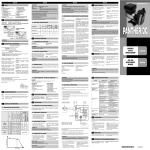
INDEX
A
DECLARATION OF CONFORMITY
B
GENERAL WARNINGS
C
SAFETY INSTRUCTIONS
C.1
SAFETY WARNINGS
C.2
FIRST AID RULES
C.3
GENERAL SAFETY RULES
C.4PACKAGING
C.5
PACKAGE CONTENTS/PRE-INSPECTION
D
BECOMING ACQUAINTED WITH K24
D.1
COMPATIBLE LIQUIDS
D.2
DISPLAY LCD
D.3
DISPLAY POSITIONING (METER VERSION ONLY)
D2 USERS BUTTONS
E
OPERATING MODES
F
INSTALLATION
G
DAILY USE
G.1
DISPENSING IN NORMAL MODE
G.1.1
PARTIAL RESET (NORMAL MODE)
G.1.2
RESETTING THE RESET TOTAL
G.2
DISPENSING WITH FLOW RATE MODE DISPLAY
G.2.1
PARTIAL RESET (FLOW RATE MODE)
H
CALIBRATION
H1DEFINITIONS
H2
CALIBRATION MODE
H.2.1
DISPLAY OF CURRENT CALIBRATION FACTOR AND
RESTORING FACTORY FACTOR.
H.2.2
IN FIELD CALIBRATION
H.2.2.1
IN-FIELD CALIBRATION PROCEDURE
H.2.3
DIRECT MODIFICATION OF K FACTOR
I
METER CONFIGURATION
LMAINTENANCE
MMALFUNCTIONS
NDISPOSAL
O
DATI TECNICI / TECHNICAL DATA
P
EXPLODED VIEWS AND OVERALL DIMENSIONS
A
DECLARATION OF CONFORMITY
The undersigned:
PIUSI S.p.AVia Pacinotti c.m. z.i.Rangavino
46029 Suzzara - Mantova - Italy
HEREBY STATES
under its own responsibility, that the equipment described below:
Descriprion: METER
Model: K24
Serial number: refer to Lot Number shown on CE plate affixed to productYear of
manufacture: refer to the year of production shown on the CE plate affixed to the
productis in conformity with the legal provisions indicated in the directives :
- Electromagnetic Compatibility Directive 2004/108/EC
The documentation is at the disposal of the competent authority following motivated
request at Piusi S.p.A. or following request sent to the email address: doc_tec@
piusi.comThe person authorised to compile the technical file and draw up the declaration is Otto Varini as legal representative.
Suzzara, 01/01/2010
Otto Varini
legal representative.
B
GENERAL WARNINGS
Important
precautions
Symbols used
in the manual
Manual preservation
Reproduction
rights
C
C.1
his manual should be complete and legible throughout. It
should remain available to end users and specialist installation
and maintenance technicians for consultation at any time.
All reproduction rights are reserved by Piusi S.p.A. The text cannot be reprinted without the written permission of Piusi S.p.A.
THIS MANUAL IS THE PROPERTY OF Piusi S.p.A.
ANY REPRODUCTION, EVEN PARTIAL, IS FORBIDDEN.
SAFETY WARNINGS
ATTENTION
You must avoid any contact between the electrical power supply and the fluid that needs to be FILTERED.
Before any checks or maintenance work are carried out, disconnect the power source.
When metering flammable liquids, observe precautions
against fire or explosion
When handling hazardous liquids, always follow the liquid
manifacturer’s safety precautions
Always dispose of used cleaning solvents in a safe manner
according to the solvent manifacturer’s instructions.
During meter removal, liquid may spill. Follow the liquid
manifacturer’s safety precautions to clean up minor spills
Do not blow compressed air through the meter
Do not allow liquids to dry inside the meter
NOTE
In the event of problems developing following EYE/SKIN
CONTACT, INHALATION or INGESTION of the treated product,
please refer to the SAFETY DATA SHEET of the fluid handled.
Please refer to the safety data sheet for the product
SMOKING
PROHIBITED
When operating the dispensing system and in particular during refuelling, do not smoke and do not use open flame.
ATTENTION
When metering flammable liquids, observe precautions against fire or explosion
When handling hazardous liquids, always follow the
liquid manifacturer’s safety precautions.
Do not submerge the meter
2 - weight of the contents
1 - Normal
Mode
2 - Flow rate
Mode
3 - description of the
product
FOREWORD
NOTE
To open the packaging, use a pair of scissors or a cutter, being careful
not to damage the dispensing system or its components.
In the event that one or more of the components described below are missing from inside the package,
please contact Piusi inc technical support.
Check that the data on the plate correspond to the
desired specifications. In the event of any anomaly,
contact the supplier immediately, indicating the nature
of the defects. Do not use equipment which you suspect
might not be safe.
WARNING
D
F
PACKAGE CONTENTS/PRE-INSPECTION
FOREWORD
D.1
COMPATIBLE LIQUIDS
The turbine is placed inside a hole through the body of k24, fitted with
Turbine
measurement M-f threaded inlet and outlet.
The liquids compatible with k24 are at low viscosity, namely:
system
Connections
ATTENTION
G
DO NOT USE WITH SUNDRIES LIQUIDS
Main components K24 Meter
close-fitting clothing;
protective gloves;
safety goggles;
Protective
equipment
instruction manual
WARNING
If handling hazardous liquids, always follow the Liquid
Manifacturer’s Safety Precautions. Wear protective
clothing such as goggles, gloves and respirator as
instructed.
When metering flammable liquids, observe precautions against fire or explosion. Do not meter in the presence of any source of ignition including running or hot
engines, lighted cigarettes, or gas or electric heaters
For installations on system, position meter so that the
battery housing can be easily reached.
To protect against the leakage, make sure all threads are
sealed with two or three turns of thread tape or a sealing
compound compatible with the liquid being metered
Make sure the thread tape or sealing compound does
interfere with flow
Make sure there are no leaks in the connections.
To seal leaks, remove and inspect the meter and replace the thread tape or sealant. Refer to the Troubleshooting Section
DAILY USE
FOREWORD
The only operations that need to be done for daily use are partial and/
or resettable total register resetting. The user should use only the dispensing system of k24. Occasionally the meter may need to be configured or calibrated. To do so, please refer to the relevant chapters.
Below are the two typical normal operation displays. One display page shows the partial and reset total registers. The other shows the partial and general total. Switchover
from resettable total to general total display is automatic and tied to phases and times
that are in factory set and cannot be changed.
LCD display
RESET key
CAL key
Technical data plate
NOTA
6 digits are available for Totals, plus two icons x 10 /
x100. The increment sequence is the following:
0.0 -> 99999.9 -> 999999 -> 100000 x 10 -> 999999 x
10 ->100000 x 100 -> 999999 x 100
Main components K24 Pulser
1
Plate with technical data
G.1
DISPENSING IN NORMAL MODE
FOREWORD
WARNING
4
1
2 1
3
STAND BY
Normal mode is the standard dispensing. While the count is made, the
partial and resettable total are displayed at the same time (reset total).
Should one of the keys be accidentally pressed during
dispensing, this will have no effect.
A few seconds after dispensing has ended, on the lower register, the
display switches from resettable total to general total: the word reset
above the word total disappears, and the reset total is replaced by
the general total.
This situation is called standby and remains stable until the user
operates the k24 again.
D.2
1
The word “Gal” remaining alongside the flow rate
refers to the register of the Totals (Reset or NON Reset)
which are again displayed when exiting from the flow
rate reading mode.
To return to “Normal” mode, press the CAL key again. If one of the two keys RESET or
CAL is accidentally pressed during the count, this will have no effect.
IMPORTANT
2
3
4
5
Totals register (6 figures with moving 9
comma FROM 0.1 to 999999), that can
indicate two types of Total:
4.1. General Total that cannot be reset (TOTAL)
4.2. Resettable total (Reset TOTAL)
Indication of total multiplication factor
(x10 / x100)
Indication of unit of measurement of
Partial: Qts=Quarts Pts=Pints
L=Litres Gal=Gallons
The partial register can be reset by pressing the reset key when
the meter is in standby, meaning when the display screen
shows the word “TOTAL”.
8
7
3
4
5
6
D.3
ATTENTION
The square shape of the k24 body allows the card to be rotated in its
housing, thus ensuring great versatility in positioning
This allows easy display readings in any position. The card housing
is closed by a plastic cover sealed through a rubber protection acting as a gasket as well. This can be easily removed unscrewing the
4 screws that fix both the cover and the card (1).
G.1.2 RESETTING THE RESET TOTAL
While fixing the K24 card, make sure the battery contact cable is not placed above the circular housing of
the bulb.
VALID JUST FOR METER VERSION WITH SILVER LABEL
The reset total resetting operation can only be performed
after resetting the partial register. The reset total can in
fact be reset by pressing the reset key at length while
the display screen shows reset total as on the following
display page:
Schematically, the steps to be taken are:
1 Wait for the display to show normal standby display page
(with total only displayed)
2 Press the reset key quickly
3 The meter starts to reset the partial
4 While the display page showing the reset total is displayed
Press the reset key again for at least 1 second
D4
USERS BUTTONS
FOREWORD
MAIN
FUNCTIONS
PERFORMED
SECONDARY
FUNCTIONS
LEGEND
SHORT
PRESSURE
OF CAL
KEY
The display screen again shows all the segments of the
display followed by all the switched-off segments and
finally shows the display page where the reset Reset
Total is shown.
CAL
The METER features two buttons (RESET and CAL) which individually perform two main functions and, together, other secondary
functions.
- for the RESET key, resetting the partial register and Reset Total
- for the CAL key, entering instrument calibration mode
Used together, the two keys permit entering configuration mode
where the desired unit of measurement can be set.
CALIBRATE MEANS PERFORMING ACTIONS ON THE METER KEYS.
BELOW IS THE LEGEND OF THE SYMBOLS USED TO DESCRIBE
THE ACTIONS TO BE PERFORMED
SHORT
LONG
LONG
PRESRESET
RESET
RESET
RESET
CAL PRESCALCAL
PRESSURE
SURE
SURE
OF
OF
OF CAL
RESET
RESET
KEY
KEY
KEY
DISPENSING WITH FLOW RATE MODE DISPLAY
Every short press of the RESET key, the various combinations
of the units of measurements are scrolled as shown below:
Gal
RESET
Qts
RESET
5
H1DEFINITIONS
Multiplication factor applied by the system to the electrical pulses
received, to transform these into measured fluid units.
Factory-set default factor. It is equal to 1,000. This calibration factor
ensures utmost precision in the following operating conditions:
Fluid
diesel
Temperature: 20°C
Flow rate:
50 lit/min (13 GPM)
Even after any changes have been made by the user, the factory k
factor can be restored by means of a simple procedure.
USER K FACTOR: Customized calibration factor, meaning modified by calibration.
H2
Indicated value
Real value
SHORT RESET key keying
The Meter is informed that the calibration dispensing
operation is finished.
Make sure dispensing is correctly finished before performing
this operation. To calibrate the Meter, the value indicated by
the partial totaliser (example 9.800) must be forced to the
real value marked on the graduated sample container. In the
bottom left part of the display an arrow appears (upwards and
downwards), that shows the direction (increase or decrease) of
the value change displayed when the following operations 6
or 7 are performed.
SHORT RESET key keying
The arrow changes direction. The operation can be repeated to
alternate the direction of the arrow.
CALIBRATION
RESET
6
7
CAL
CAL
CALCAL
CALIBRATION MODE
Why calibrate?
1
2
Display the currently used calibration factor:
Return to factory calibration (Factory K Factor) after a previous calibration by the user
Change the calibration factor using one of the two previ3
ously indicated procedures
Two procedures are available for changing the Calibration Factor:
FOREWORD
1
In-Field Calibration, performed by means of a dispensing
operation
2
Direct Calibration, performed by directly changing the
calibration factor
In calibration mode, the partial and total dispensed quantities indicated on the display
screen take on different meanings according to the calibration procedure phase.
In calibration mode, the K24 cannot be used for normal dispensing operations.
In “Calibration” mode, the totals are not increased
The K24 features a non-volatile memory that keeps
the data concerning calibration and total dispensed
quantity stored for an indefinite time, even in the
case of a long power break; after changing the batteries, calibration need not be repeated.
H.2.1 DISPLAY OF CURRENT CALIBRATION FACTOR
AND RESTORING FACTORY FACTOR.
By pressing the CAL key while the appliance is in Standby, the display page appears showing the current calibration factor used. If no calibration has ever been
performed, or the factory setting has
been restored after previous calibrations,
the following display page will appear:
The word “Fact” abbreviation for “factory”
shows that the factory calibration factor
is being used
If, on the other hand, calibrations have
been made by the user, the display page
will appear showing the currently used
calibration factor ( in our example 0,998) .
The word “user” indicates a calibration factor set by the user is being used..
CAL
CALCAL
8
10
ACTION
1
RESET
CAL
CAL
CALCAL
2
RESET
RESET
RESET
TIME OUT
3
This procedure calls for the fluid to be dispensed into a graduated sample container in real operating conditions ( flow rate,
viscosity, etc.) requiring maximum precision.
4
5
CAL
CAL
CALCAL
For correct K24 calibration, it is most important to:
1 When the Factory Factor is confirmed, the old User factor is deleted
VALID JUST FOR METER VERSION WITH SILVER LABEL
It is possible to dispense fluids, displaying at the same
time::
1 the dispensed partial
2
2 the Flow Rate in [Partial Unit / minute] as shown on the
following display page:
Procedure for entering this mode:
1 wait for the Remote Display to go to Standby, meaning
the display screen shows Total only
2 quickly press the CAL key.
3 Start dispensing
4
The flow rate is updated every 0.7 seconds. Consequently, the display could be relatively
unstable at lower flow rates. The higher the flow rate, the more stable the displayed
value.
6
3
5
Old Cal Factor *
(
2
from the memory
use a precise Sample Container with a capacity of not less than 5
litres, featuring an accurate graduated indicator.
ensure calibration dispensing is done at a constant flow rate equivalent to that of normal use, until the container is full;
Not reduce the flow rate to reach the graduated area of the container during the final dispensing stage (the correct method during
the final stages of sample container filling consists in making short
top-ups at normal operation flow rate) ;
after dispensing, wait a few minutes to make sure any air bubbles
are eliminated from the sample container; only read the Real value
at the end of this stage, during which the level in the container could
drop.
Carefully follow the procedure indicated below.
RESET
RESET
RESET
7
8
9
LONG CAL KEY KEYING
Meter enters calibration mode, shows “CAL” and displays the
calibration factor being used instead of the partial. The words
“Fact” and “User” indicate which of the two factors (factory or
user) is currently being used.
LONG RESET KEY KEYING
The Meter shows “CAL” and the zero partial total.
Meter is ready to perform in-field calibration by dispensing –
see previous paragraph.
LONG RESET KEY KEYING
We now go on to Direct change of the calibration factor:
the word “Direct” appears together with the Currently Used
calibration factor. In the bottom left part of the display, an
arrow appears (upwards or downwards) defining the direction
(increase or decrease) of change of the displayed value when
subsequent operations 5 or 6 are performed.
SHORT RESET KEY KEYING
Changes the direction of the arrow. The operation can be
repeated to alternate the direction of the arrow.
SHORT/LONG CAL KEY KEYING
The indicated value changes in the direction indicated by the
arrow
- one unit for every short CAL key keying
- continually if the CAL key is kept pressed. The speed increase
rises by keeping the key pressed. If the desired value is
exceeded, repeat the operations from point (5).
LONG RESET KEY KEYING
The Meter is informed that the calibration procedure is
finished.
Before performing this operation, make sure the INDICATED
value is that required.
NO OPERATION
At the end of the calculation, the new USER K FACTOR is shown
for a few seconds, after which the restart cycle is repeated to
finally achieve standby condition.
IMPORTANT: From now on, the indicated factor will become
the calibration factor used by the Meter and will continue to
remain such even after a battery change
NO OPERATION
The Meter stores the new work calibration factor and is ready
to begin dispensing, using the USER K FACTOR that has just
been changed.
If K24 operation continues without changing the batteries,
the second battery alarm level will be reached which will
prevent operation. In this condition the battery icon starts to
flash and is the only one to remain visible on the LCD.
TO REMOVE BATTERY
ATTENTION
1
2
3
100 - E%
100
NONE
METER in Standby.
K24 should be installed in a position allowing the
batteries to be replaced without removing it from
the system.
Check the batteries and terminals at least every
year to ensure proper operation. It is strongly recommended that terminals be cleaned annually
K24 features two low-battery alarm levels:
1
When the battery charge falls below the first level on the LCD,
the fixed battery symbol appears. In this condition, K24 continues to operate correctly, but the fixed icon warns the user
that it is ADVISABLE to change the batteries.
)
To change the
batteries, with
reference to the
exploded diagram
positions, proceed
as follows
During meter removal, liquid may spill. Follow the
liquid manifacturer’s safety precautions for clean
up of minor spills.
Ensure all liquid is drained from the meter. This could
include draining the hose, meter, nozzle or pipe
Wear protective clothing as necessary, loosen both ends
of the meter. Use a wrench only on the meter’s flat metal
surfaces
If the meter is not immediately installed again, cap the
hose end or pipe to prevent spills
Press RESET to update all the totals
Loosen the 4 fixing screws of the lower cover
Remove the old batteries and disconnect the plug
Place the new batteries in the same position as the old ones
(sure to put the battery in the correct way)
5
close the cover again, by positioning the rubber protection as a gasket
6
K24 will switch on automatically and normal operation can be resumed
The K24 will display the same Reset Total, the same Total and the same Partial indicated before the batteries were changed.
After changing the batteries, the meter does not need calibrating again.
1
2
3
4
ATTENTION
Never blow compressed air trought the meter. It
could damage the rotor.
CLEANING
Only one operation is necessary to clean the k24.
After removing k24 from the plant where it was built
in, any residual elements can be removed by washing
or mechanically-handling.
If this operation does not restore a smooth rotation of
the turbine, it will have to be replaced.
DISPLAY
RESET
H.2.2 IN FIELD CALIBRATION
ATTENTION
=
Use 2x1.5 V alkaline batteries size AAA
BATTERIES
Example:
Error percentage found: E% - 0.9 %
CURRENT calibration factor: 1.000
New USER K FACTOR:
1.000 * [(100 – ( - 0.9))/100] = 1.000 * [(100 + 0.9)/100] = 1.009
If the Meter indicates less than the real dispensed value (negative error) the new calibration factor must be higher than the old one as shown in the example. The opposite applies if the Meter shows more than the real dispensed value (positive error).
When the Factory Factor is confirmed, the old User
factor is deleted from the memory
FOREWORD
BATTERY
REPLACEMENT
WARNING
SHORT/LONG CAL key keying
The indicated value changes in the direction indicated by the
arrow
- one unit for every short CAL key keying
- continually if the CAL key is kept pressed. The speed increase
rises by keeping the key pressed. If the desired value is
exceeded, repeat the operations from point (6).
New cal. Factor
The Reset Total and Total registers will be automatically changed to the new unit of measurement.
NO new calibration is required after changing the
Unit of Measurement.
MANUALE D’USO, MANUTENZIONE
E CALIBRAZIONE
Italiano
USE, MAINTENANCE AND
CALIBRATION MANUAL
English
Bulletin
LMAINTENANCE
H.2.3 DIRECT MODIFICATION OF K FACTOR
RESET
RESET
RESET
ATTENTION
4
ATTENTION
Indicated value
Real value
The Meter calculates the new USER K FACTOR ; this calculation
could require a few seconds, depending on the correction to
be made
ATTENTION: If this operation is performed after action (5),
without changing the indicated value, the USER K FACTOR would
be the same as the FACTORY K FACTOR, thus it is ignored.
NO OPERATION
At the end of the calculation, the new USER K FACTOR is shown
for a few seconds, after which the restart cycle is repeated to
finally achieve standby condition.
IMPORTANT: From now on, the indicated factor will become
the calibration factor used by the Meter and will continue to
remain such even after a battery change
NO OPERATION
The Meter stores the new work calibration factor and is
ready to begin dispensing, using the USER K FACTOR that
has just been calculated..
9
Gal
By pressing the CAL key at length, the new settings will
be stored, the METER will pass through the start cycle and
will then be ready to dispense in the set units.
CAL
CALCAL
If normal Meter operation shows a mean percentage error, this can be corrected by applying to the currently used calibration factor a correction of the same percentage. In this
case, the percentage correction of the USER K FACTOR must be calculated by the operator in the following way
CAL
The flow chart alongside
shows the switchover logic
from one display page to
another
In this condition, the Reset
key permits switching
from User factor to Factory
factor.
To confirm the choice of
calibration factor, quickly
press CAL while “User” or
“Fact” are displayed.
After the restart cycle, the
K24 uses the calibration
factor that has just been
confirmed
RESET
LONG RESET key keying
The Meter is informed that the calibration procedure is finished.
Before performing this operation, make sure the INDICATED
value is the same as the REAL value.
.
RESET
RESET
RESET
6
C.2
Then press the CAL and RESET keys together. Keep these pressed
until the word “UNIT” appears on the screen together with the unit of
measurement set at that time (in this example Litres / Litres )
CAL
Pts
When operating close to extreme use or flow rate conditions (close to minimum or
maximum acceptable values), an on-the-spot calibration may be required to suit
the real conditions in which the K24 is required to operate.
CALIBRATION
FACTOR OR
“K FACTOR”
FACTORY K
FACTOR
METER - PULSER
RESET
RESET
5
2
3
+
then quickly press RESET
H
ELECTRONIC ALLUMINIUM
TURBINE
Unit of Measurement
Totals Register
Litres (L)
Gallons (Gal)
Gallons (Gal)
Gallons (Gal)
To choose between the 4 available combinations:
Wait for the METER to go to Standby
1
Dispensing can be interrupted and started again at will.
Continue dispensing until the level of the fluid in the sample
container has reached the graduated area. There is no need to
reach a preset quantity.
CAL
CALCAL
DISPLAY POSITIONING (METER VERSION ONLY)
FOREWORD
Unit of Measurement
Partial Register
Litres (L)
Gallons (Gal)
Quarts (Qts)
Pints (Pts)
1
2
3
4
DISPENSING INTO SAMPLE CONTAINER
Without pressing any key, start dispensing into the sample
container
G.2.1 PARTIAL RESET (FLOW RATE MODE)
After pressing the reset key, during reset, the display screen
first of all shows all the lit-up digits and then all the digits that
are not lit up.
and, after a few moments, the reset total is replaced by the
non resettableTotal.
METER CONFIGURATION
RESET
3
4
To reset the Partial Register, finish dispensing and wait for
the Remote Display to show a Flow Rate of 0.0 as indicated
in the illustration
9
2
RESET
RESET
RESET
I
The METER feature a menu with which the user can select the main measurement unit,
Quarts (Qts), Pints (Pts), Litres (Lit), Gallons (Gal);
The combination of the unit of measurement of the Partial register and that of the
Totals is predefined according to the following table:
Combination no.
LONG CAL key keying
The Meter enters calibration mode, shows <<CAL>> and
displays the calibration factor in use instead of partial. The
words “Fact” and “USER” indicate which of the two factors
(factory or user) is currently in use.
Important: This factor is that which the instrument also uses for
field calibration measurement operations
LONG RESET key keying
The Meter shows “CAL” and the partial at zero. The Meter is
ready to perform in-field calibration.
Even though in this mode they are not displayed, both the
Reset Total and the General Total (Total) increase. Their
value can be checked after dispensing has terminated,
returning to “Normal” mode, by quickly pressing CAL.
At the end of the process, a display page is first of all shown
with the reset partial and the reset total
1
DISPLAY
NONE
Meter in Standby
2
DISPLAY LCD
G.1.1 PARTIAL RESET (NORMAL MODE)
IN-FIELD CALIBRATION PROCEDURE
CAL
CALCAL
FOREWORD
The “LCD” of the METER features two numerical registers and various
indications displayed to the user only when the applicable function
so requires.
Partial register (5 figures with moving 6 Indication of type of total, (TOTAL /
comma FROM 0.1 to 99999) indicating
Reset TOTAL);
the volume dispensed since the reset
button was last pressed
Indication of battery charge
7 Indication of unit of measurement of
Totals:
L=Litres Gal=Gallons
Indication of calibration mode
8 Indication of Flow Rate mode
H.2.2.1
ACTION
1
K24
ENGLISH
ENGLISH
The flow rate is measured with reference to the unit of
measurement of the Partial. For this reason, in case of
the unit of measurement of the Partial and Total being
different, as in the example shown below, it should be
remembered that the indicated flow rate relates to
the unit of measurement of the partial. In the example
shown, the flow rate is expressed in Qts/min.
ATTENTION
Wear protective equipment that is:
suited to the operations that need to be performed;
resistant to cleaning products.
Wear the following personal protective equipment during
handling and installation:
safety shoes;
K24 features a threaded, perpendicular inlet and outlet (1” NPT or
BSP male and female that can be combined together). It has been
designed to be easily installed in any position: fixed in-line or mobile
on a dispensing nozzle. In order to improve the life of the turbine, it is
recommended to fit a strainer before the meter itself
Diesel fuel
Kerosene
Gasoline
Gasoline blended alcol max 15%
ATTENTION
1
2
3
4
ATTENTION
Electronic digital meter featuring a turbine measurement system, designed for precise measuring of low viscosity fluids.
K24 is a bi-directional meter with LCD display and calibration
buttons. The body is made of aluminum (conductive) and designed for high flow 120 l/min. (32 GPM).
K24 is available in 3 versions:
1
a
METER – with LCD display and calibration buttons (SILVER LABEL)
b
METER – with LCD display and calibration buttons (RED LABEL)
2
PULSER – single-channel impulse, cannectable with a remote display.
IMPORTANT
The user can choose between two different operating modes:
The meter features a non-volatile memory for storing the dispensing
data, even in the event of a complete power break for long periods.
The measurement electronics and the LCD display are fitted in the top
part of the K24 which remains isolated from the fluid-bath measurement chamber and sealed from the outside by means of a cover.
Normal Mode: Mode with display of Partial and Total dispensed quantities
Flow Rate Mode: Mode with display of Flow Rate, as well as
Partial dispensed quantity.
INSTALLATION
FOREWORD
BECOMING ACQUAINTED WITH K24
GENERAL SAFETY RULES
Essential protective equipment characteristics
Personal protective equipment that
must be worn
OPERATING MODES
OPERATING
MODES
FIRST AID RULES
Contact with
the product
C.3
K24 comes packed in a cardboard box with a label indicating the following data:
1 - contents of the package
ATTENTION
This symbol indicates safe working practices for operators and/or potentially exposed persons.
WARNING
This symbol indicates that there is risk of damage to the
equipment and/or its components.
NOTE
This symbol indicates useful information.
SAFETY INSTRUCTIONS
Mains - preliminary checks
before installation
Maintenance
control
For your safety,
review the major warnings
and cautions
below before
operating your
meter
C.2
To ensure operator safety and to protect the pump from potential damage, workers must be fully acquainted with this
instruction manual before performing any operation.
The following symbols will be used throughout the manual
to highlight safety information and precautions of particular
importance:
E
C.4PACKAGING
FOREWORD
C.5
ENGLISH
ENGLISH
ATTENTION
TO STORE
M0225 ITEN rev. 0
MMALFUNCTIONS
Problem
LCD: no indication
Possible cause
Bad battery contact
Wrong K FACTOR
Not enough measureThe meter works below
ment precision
minimum acceptable flow
rate.
Reduced or zero flow
TURBINE blocked
rate
Incorrect installation of
The meter does not
gears after cleaning
count, but the flow
Possible electronic card
rate is correct
problems
Battery discharged or installed
K24 is switched of
in the wrong way
Remedial Action
Check battery contacts
With reference to paragraph
H, check the K FACTOR
Increase the flow rate until an
acceptable flow rate range has
been achieved
Clean the TURBINE
Repeat the reassembly procedure
Contact your dealer
Check battery charge and/or
check the battery position
NDISPOSAL
Foreword
Disposing of packing materials
Metal Parts Disposal
Disposal of electric
and electronic
components
Information regarding the environment
for clients
residing
within the European Union
Miscellaneous
parts disposal
P
If the system needs to be disposed, the parts which make it up
must be delivered to companies that specialize in the recycling
and disposal of industrial waste and, in particular:
The packaging consists of biodegradable cardboard which can be
delivered to companies for normal recycling of cellulose.
Metal parts, whether paint-finished or in stainless steel, can be
consigned to scrap metal collectors.
These must be disposed of by companies that specialize in the
disposal of electronic components, in accordance with the indications of directive 2002/96/CE (see text of directive below).
European Directive 2002/96/EC requires that all equipment
marked with this symbol on the product and/or packaging not
be disposed of together with non-differentiated urban waste.
The symbol indicates that this product must not be disposed of
together with normal household waste. It is the responsibility of
the owner to dispose of these products as well as other electric or
electronic equipment by means of the specific refuse collection
structures indicated by the government or the local governing
authorities.
Other components, such as pipes, rubber gaskets, plastic parts
and wires, must be disposed of by companies specialising in the
disposal of industrial waste.
EXPLODED VIEWS AND OVERALL DIMENSIONS
/VISTE ESPLOSE ED INGOMBRI
Do not discard the old batteries in the environment.
Refer to local disposal regulations.
Do not use compressed air onto the turbine in order
to avoid its damage because of an excessive rotation
Follow the liquid manifacturer’s instructions for the
disposal of contaminated cleaning solvents
K24 Front face replacement
Carefully remove the screws from the corners of the
1
front panel, and then carefully lift the front cover up
away from the main body of the meter.
2
Carefully remove the screws from the corners of the
front panel, and then carefully lift the front cover up
away from the main body of the meter.
3
When the new panel is fitted make sure the power
adapter is fitted correctly with the location pin in the
correct way
4
Carefully refit the display panel back onto the main
body making sure the wire is tucked into the corner
and replace the screws
74.7
PULSER
45.78
112.5
ENGLISH
ENGLISH
1"NPT
59.6
76.3
ITALIANO
INDICE
A
DICHIARAZIONE DI CONFORMITA’
B
AVVERTENZE GENERALI
C
ISTRUZIONI DI SICUREZZA
C.1
AVVERTENZE DI SICUREZZA
C.2
NORME DI PRONTO SOCCORSO
C.3
NORME GENERALI DI SICUREZZA
C.4IMBALLO
C.5
CONTENUTO DELL’IMBALLO
D
CONOSCERE K24
D.1
LIQUIDI COMPATIBILI
D.2
DISPLAY LCD
D.3
ORIENTAMENTO DISPLAY (SOLO VERSIONE METER)
D.4 PULSANTI UTENTE - LEGENDA
E
MODALITÀ DI UTILIZZO
FINSTALLAZIONE
G
USO GIORNALIERO
G.1
EROGAZIONE IN MODALITÀ NORMALE (NORMAL MODE)
G1.1
AZZERAMENTO DEL PARZIALE
G1.2
AZZERAMENTO DEL RESET TOTAL (TOTALE AZZERABILE)
G.2
EROGAZIONE CON VISUALIZZAZIONE PORTATA ISTANTANEA (FLOW RATE MODE)
G.2.1
AZZERAMENTO DEL PARZIALE
H
CALIBRAZIONE
H.1DEFINIZIONI
H.2
MODALITÀ DI CALIBRAZIONE
H.2.1
VISUALIZZAZIONE“K FACTOR”ATTUALE E RIPRISTINO DEL“FACTORY K FACTOR”.
H.2.2
CALIBRAZIONE IN CAMPO
H.2.2.1
PROCEDURA PER EFFETTUARE LA CALIBRAZIONE IN CAMPO
H.2.3 MODIFICA DIRETTA DEL K FACTOR
I
CONFIGURAZIONE DEI CONTALITRI
LMANUTENZIONE
MMALFUNZIONAMENTI
NSMALTIMENTO
O
DATI TECNICI
P
VISTE ESPLOSE ED INGOMBRI
A
DICHIARAZIONE DI CONFORMITA’
La sottoscritta:
PIUSI S.p.A
Via Pacinotti c.m. z.i.Rangavino
46029 Suzzara - Mantova - Italia
DICHIARA
sotto la propria responsabilità, che l’apparecchiatura descritta in appresso:
Descrizione : Contalitri
Modello : K24
Matricola: riferirsi al Lot Number riportato sulla targa CE apposta sul prodotto
Anno di costruzione: riferirsi all’anno di produzione riportato sulla targa CE apposta sul prodotto.
è conforme alle disposizioni legislative che traspongono le direttive :
- Direttiva Compatibilità Elettromagnetica 2004/108/CE
La documentazione è a disposizione dell’autorità competente su motivata richiesta presso Piusi S.p.A. o richiedendola all’indirizzo e-mail: [email protected]
La persona autorizzata a costituire il fascicolo tecnico e a redigere la dichiarazione è Otto
Varini in qualità di legale rappresentante.
Suzzara, 01/01/2010
Otto Varini
legale rappresentante
B
AVVERTENZE GENERALI
Avvertenze
importanti
Simbologia
utilizzata nel
manuale
Per salvaguardare l’incolumità degli operatori, per evitare possibili
danneggiamenti e prima di compiere qualsiasi operazione, è indispensabile aver preso conoscenza di tutto il manuale istruzioni.
Sul manuale verranno utilizzati i seguenti simboli per evidenziare indicazioni ed avvertenze particolarmente importanti:
Conservazione del manuale
Diritti di riproduzione
C
ISTRUZIONI DI SICUREZZA
C.1
AVVERTENZE DI SICUREZZA
ATTENZIONE
Rete elettrica
- verifiche preliminari all’installazione
Interventi di
controllo manutenzione
Ai fini della
sicurezza,
rispettare gli
avvisi e le avvertenze sotto
specificati prima di mettere
in funzione il
contalitri.
C.2
Evitare assolutamente il contatto tra l’alimentazione
elettrica e il liquido da pompare.
Prima di qualsiasi intervento di controllo o manutenzione,
togliere L’ALIMENTAZIONE5
In caso di utilizzo di liquidi infiammabili, osservare le precauzioni contro i rischi di incendio o di esplosione
In caso di travaso di liquidi pericolosi, seguire sempre le precauzioni di sicurezza del produttore del liquido
Smaltire sempre i solventi utilizzati per la pulizia in modo
sicuro, secondo le istruzioni del produttore del solvente.
Durante la rimozione del contalitri, può verificarsi la fuoriuscita di liquido. Seguire le precauzioni di sicurezza del produttore del liquido per la pulizia di piccole fuoriuscite
Non soffiare aria compressa attraverso il contalitri
Evitare che i liquidi si secchino all'interno del contalitri
NORME DI PRONTO SOCCORSO
ATTENZIONE
C.3
1 - Normal
Mode
2 - Flow rate
Mode
Premessa
C5
CONTENUTO DELL’IMBALLO
Per aprire l’imballo, utilizzare delle forbici o un taglierino.
PREMESSA
NOTA
Nel caso in cui uno o più componenti di seguito descritti
non siano presenti all’interno della confezione, contattare il servizio di assistenza tecnica Piusi S.p.A.
Verificare che i dati di targa corrispondano a quelli desiderati. Per qualsiasi anomalia, contattare immediatamente il
fornitore, segnalando la natura dei difetti e, in caso di dubbio sulla sicurezza dell’apparecchiatura, non utilizzarla.
ATTENZIONE
D
D1
LIQUIDI COMPATIBILI
Sistema di
misura a
turbina
ATTENZIONE
La turbina è posizionata all’interno di un foro che attraversa il corpo del
K24 e dotato di ingresso ed uscita filettati M-F. I liquidi compatibili con
il K24 SONO A bassa viscosità e precisamente i seguenti:
Gasolio
Kerosene
Benzina
Benzina con alcool al 15% max
Componenti Principali K24 METER
Display LCD
Tasto RESET
Tasto CAL
Targhetta dati tecnici
Componenti Principali K24 Pulser
1
indumenti attillati al corpo;
ATTENZIONE
G
Per proteggere contro le perdite, assicurarsi che tutti i
filetti siano chiusi con due o tre giri di nastro o composto sigillante compatibili con il liquido misurato
Assicuratevi che il nastro o composto sigillante non
interferisca con il flusso
Assicurarsi che non vi siano perdite nei collegamenti.
Per sigillare le perdite, smontare e controllare il contalitri e sostituire il nastro o composto sigillante. Consultare la sezione Risoluzione dei problemi
Le uniche operazioni che vengono compiute nell’utilizzo giornaliero
sono gli azzeramenti dei registri del parziale e/o del totale resettabile. Puo’ occasionalmente essere necessario configurare o calibrare il
contalitri. A tal proposito, fare riferimento ai capitoli specifici.
Vengono di seguito riportate le due visualizzazioni tipiche del funzionamento normale.
In una schermata è visibile il registro del parziale e quello del totale azzerabile (reset
total). Nell’altra viene mostrato il parziale ed il totale generale. Il passaggio tra la visualizzazione del totale resettabile e del totale generale è automatica ed è legata a fasi e
temporizzazioni impostate in fabbrica e non modificabili
NOTA
I digit disponibili per i totali sono 6 a cui si aggiungono due icone x 10 / x100.La sequenza di incremento
è la seguente: 0.0 -> 99999.9 -> 999999 -> 100000 X
10 -> 999999 x 10 -> 100000 x 100 -> 999999 x 100
EROGAZIONE IN MODALITÀ NORMALE (NORMAL MODE)
AVVERTENZA
STAND BY
DISPLAY LCD (SOLO VERSIONE METER)
Normal mode è l’erogazione standard. Durante il conteggio, vengono visualizzati contemporaneamente il “parziale erogato” ed il “totale
azzerabile” (reset total).
Premere accidentalmente i tasti durante l’erogazione, non comporta alcun effetto
Ad alcuni secondi dal termine dell’erogazione, sul registro inferiore la visualizzazione passa dal “totale azzerabile” al ”totale generale”:
la scritta reset posta sopra alla scritta total scompare, ed il valore del “totale
azzerabile”, viene sostituito dal “totale generale”.
Questa situazione viene definita di riposo (o STAND-BY) e rimane stabile
fino a quando l’utente non effettua altre operazioni.
Premessa
1
2
3
4
5
L’ «LCD» del contalitri è provvisto di due registri numerici e di diverse
indicazioni che vengono visualizzate dall’utente solamente se la funzione del momento lo richiede
Registro del parziale (5 cifre a virgola
6 Indicazione del tipo di totale, (total /
mobile da 0.1 A 99999), che indica il
reset total)
volume erogato dall’ultima volta che
è stato premuto il pulsante di reset
Indicazione dello stato di carica delle
7 Indicazione dell’unità di misura dei
batterie
totali:l=litri gal=galloni
Indicazione della modalità di calibra8 Indicazione della modalità “Portata
zione
Istantanea” (Flow Rate)
Registro dei totali (6 cifre a virgola
9 Indicazione dell’unità di misura del parziamobile da 0,1 a 999999), che può indile:
qts=quarti; pts=pinte;
care due tipi di totale:
l=litri;gal=galloni
4.1. Totale generale non azzerabile (total)
4.2. Totale azzerabile (reset total)
Indicazione del fattore di moltiplicazione dei totali (x10 / x100)
1
9
2
8
7
3
4
D3
5
6
G1.1
AZZERAMENTO DEL PARZIALE
Il Registro del Parziale può essere azzerato premendo il tasto
RESET quando il contalitri è in Stand-by, ovvero quando il display visualizza la scritta «TOTAL».
ATTENZIONE
La forma quadrata del corpo K24, permette di ruotare la scheda nella
sua sede garantendo cosi’ grande versatilita’ di orientamento.
Questo consente una facile lettura del display in tutte le posizioni.
La sede della scheda, è chiusa da un coperchio in plastica con
tenuta garantita dalla protezione in gomma che è anche guarnizione. Il tutto e’ facilmente rimuovibile svitando le 4 viti che fissano
coperchio e scheda (1).
In fase di fissaggio scheda del K24, è importante fare
attenzione che il cavo del contatto pile non si posizioni
sopra la sede circolare dell’ampolla.
G1.2
AZZERAMENTO DEL RESET TOTAL (TOTALE AZZERABILE)
VALIDO SOLO PER VERSIONE METER CON TARGA SILVER
L’operazione di azzeramento del Reset Total è effettuabile
solo successivamente ad una operazione di azzeramento del
registro del Parziale. Infatti il Reset Total può essere azzerato
premendo a lungo il tasto RESET mentre il display visualizza la
scritta RESET TOTAL come nella schermata seguente:
Schematicamente i passi da seguire sono:
1 Attendere che il display sia nella schermata normale di
stand-by (con il solo Total visualizzato)
2 Premere brevemente il tasto RESET
3 Il contalitri inizia le sue fasi di azzeramento del Parziale
4 Mentre è visualizzata la schermata che indica il Reset Total
PULSANTI UTENTE - LEGENDA
guanti di protezione;
FUNZIONI
PRINCIPALI
occhiali di sicurezza;
FUNZIONI SECONDARIE
Dispositivi di
protezione
manuale di istruzioni
LEGENDA
AVVERTENZA
In caso di travaso di liquidi pericolosi, seguire sempre le
Precauzioni di Sicurezza del Produttore del Liquido Indossare indumenti di protezione, come occhiali, guanti e
mascherina come da istruzioni.
In caso di utilizzo di liquidi infiammabili, osservare le
precauzioni contro i rischi di incendio o di esplosione
Non misurare liquidi in presenza di fonti di accensione,
inclusi motori in funzionamento o caldi, sigarette accese, o riscaldatori elettrici o a gas
PRESSIONE
BREVE
DEL
TASTO
CAL
CAL
K24 è dotato di due pulsanti (RESET e CAL) che svolgono, singolarmente, due funzioni principali e, in combinazione, altre funzioni secondarie.
- Per il tasto RESET, l’azzeramento del registro del parziale e di quello
del totale azzerabile (reset total)
- Per il tasto cal, l’entrata nella modalità di calibrazione dello strumento
Utilizzati in combinazione, i due tasti consentono di entrare in modalità di configurazione (configuration mode), utile per modifiche
sull’unita’ di misura e sul fattore di calibrazione.
CALIBRARE, SIGNIFICA OPERARE AZIONI SUI TASTI DEL CONTALITRI. DI SEGUITO, LA LEGENDA RELATIVA ALLA SIMBOLOGIA
UTILIZZATA PER DESCRIVERE LE AZIONI DA ESEGUIRE
PRESPRESSIONE
PRESSIOSIONE
PRORESET
RESET
RESET PRORESET
CAL NE
CALCAL
LUNBREVE
LUNGATA
DEL
GATA
DEL
TASTO
DEL
TASTO
RESET
TASTO
CAL
RESET
Il display torna nuovamente a mostrare tutti i segmenti
del display seguito dalla fase con tutti i segmenti spenti
per giungere alla schermata in cui viene visualizzato il
Reset Total azzerato
G.2
EROGAZIONE CON VISUALIZZAZIONE PORTATA
ISTANTANEA (FLOW RATE MODE)
VALIDO SOLO PER VERSIONE METER CON TARGA SILVER
E’ possibile effettuare erogazioni visualizzando contemporaneamente:
1 il parziale erogato
2 la Portata Istantanea (Flow Rate) in [Unità del Parziale /
minuto] come indicato nella schermata A FIANCO
Procedura per entrare in questa modalità:
1 attendere che il Meter sia in Stand-By, ovvero che il display
visualizzi il solo Total
2 premere brevemente il tasto CAL
3 Iniziare l’erogazione
La portata istantanea viene aggiornata ogni 0,7 secondi. Pertanto alle portate più basse
si potrà avere una visualizzazione relativamente instabile. Più è alta la portata maggiore
sarà la stabilità del valore letto.
CONFIGURAZIONE DEI CONTALITRI
1
2
3
4
PRESSIONE PROLUNGATA DEL TASTO CAL
entra nella modalità di calibrazione, mostra l’indicazione di
“CAL” e visualizza il fattore di calibrazione in uso al posto del
totale cumulativo. Le scritte “FACT” e “USER” stanno ad indicare
quale dei due fattori è attualmente in uso.
PRESSIONE PROLUNGATA DEL TASTO RESET
mostra l’indicazione di “CAL” e il totale parziale a zero.
Meter è pronto ad eseguire la calibrazione in campo.
Unità Misura
Registro del Parziale
Litri (Lit)
Galloni (Gal)
Quarti (Qts)
Pinte (Pts)
L’erogazione può essere interrotta e ripresa a piacere.
Continuare l’erogazione fino a quando il livello del fluido nel
recipiente campione ha raggiunto la zona graduata. Non è
necessario raggiungere una quantità prefissata.
3
RESET
CALIBRAZIONE
Quando si opera vicino alle condizioni estreme di utilizzo o di portata, (prossime ai minimi o ai massimi valori del campo ammesso), può rendersi opportuna una calibrazione in
campo, effettuata nelle reali condizioni in cui K24 deve lavorare.
5
H1DEFINIZIONI
FATTORE DI
CALIBRAZIONE
O “K FACTOR”
FACTORY K
FACTOR
Fattore moltiplicativo che il sistema applica agli impulsi elettrici ricevuti, per trasformarli in unità di fluido misurato
Fattore di calibrazione impostato di default in fabbrica. E’ uguale a
1,000. Tale fattore di calibrazione garantisce la massima precisione
nelle seguenti condizioni di utilizzo
RESET
6
7
CAL
CAL
CALCAL
Anche dopo eventuali modifiche da parte dell’utente, attraverso una semplice procedura, è possibile ripristinare il fattore di calibrazione di fabbrica.
USER K FACTOR: Fattore di calibrazione personalizzato dall’utente, ovvero modificato
da una calibrazione.
H2
RESET
RESET
RESET
MODALITÀ DI CALIBRAZIONE
Perchè
calibrare?
1
Per visualizzare il fattore di calibrazione attualmente
utilizzato
Per tornare al fattore di calibrazione di fabbrica (factory k
2
factor) dopo una precedente calibrazione con user k factor
Per Modificare il fattore di calibrazione attraverso una
3
delle due procedure indicate precedentemente
E’ possibile effettuare una rapida e precisa calibrazione
Premessa
elettronica tramite la modifica del k factor.
Esistono 2 metodi di calibrazione:
Calibrazione in campo, eseguita attraverso una erogazione
1
Calibrazione diretta, eseguita attraverso una modifica
2
diretta del k factor
In modalità di calibrazione le indicazioni di parziale erogato e cumulativo presenti sul
display, assumono significati diversi in base alla fase della procedura di calibrazione.
Durante la calibrazione, il Contalitri non può effettuare normali erogazioni. In modalità di
calibrazione i totali non vengono incrementati.
IL K24 è provvisto di memoria non volatile. Questa mantiene in
ATTENZIONE
memoria dati di calibrazione e di erogazione anche dopo la sostituzione delle batterie o lunghi periodi di inutilizzo.
H.2.1 VISUALIZZAZIONE “K FACTOR” ATTUALE E RIPRISTINO DEL “FACTORY K FACTOR”.
Premendo a lungo il tasto CAL mentre IL Contalitri
è in stand-by, si giunge alla schermata che mostra il
fattore di calibrazione attualmente utilizzato. Se lo si
sta utilizzando con il“factory k factor”, verra’mostrata
la schermata rappresentata nello schema, con la
scritta“fact”.
Se è invece stato impostato un“user k factor”, verra’
visualizzato il fattore di calibrazione impostato
dall’utente (nel nostro esempio 0.998). La scritta
“user”dà evidenza del fatto che si sta utilizzando il
fattore di calibrazione impostato dall’utente.
CAL
CALCAL
8
10
RESET
CAL
CALCAL
2
RESET
RESET
RESET
TIME OUT
Questa procedura prevede l’erogazione del fluido in un recipiente
campione graduato nelle reali condizioni operative (portata, viscosità, ecc.) alle quali è richiesta la massima precisione.
Per ottenere una corretta calibrazione del k24 è essenziale:
3
4
5
4
5
6
calibrazione
Utilizzare un preciso recipiente campione di capacità non inferiore a
5 litri, provvisto di una accurata indicazione graduata
Effettuare l’erogazione di calibrazione a portata costante pari a quella di normale utilizzo, sino al riempimento del recipiente
Non ridurre la portata per raggiungere la zona graduata del recipiente nella fase finale di erogazione (la corretta tecnica nelle fasi finali
del riempimento del recipiente campione consiste nell’effettuare
brevi rabbocchi alla portata di normale utilizzo)
Al termine dell’erogazione attendere alcuni minuti per assicurarsi
che eventuali bolle d’aria vengano eliminate dal recipiente campione; leggere il valore vero solo alla fine di tale fase, durante la quale si
potrà avere un abbassamento del livello nel recipiente
Se necessario, seguire accuratamente la procedura indicata nel seguito
CAL
CAL
CALCAL
6
RESET
RESET
RESET
1 Eliminare completamente l’aria dall’impianto prima di effettuare la
3
NESSUNA
Meter in modo normale, non in conteggio.
RESET
H.2.2 CALIBRAZIONE IN CAMPO
2
PRESSIONE PROLUNGATA DEL TASTO RESET
Meter viene cosi’ informato che la procedura di calibrazione è finita.
Prima di effettuare questa operazione, fare attenzione che il
valore INDICATO, sia uguale al valore REALE.
7
8
9
PRESSIONE PROLUNGATA DEL TASTO CAL
Meter entra nella modalità di calibrazione, e viene visualizzato
il fattore di calibrazione in uso al posto del parziale. Le scritte
“Fact” o “USER” stanno ad indicare quale dei due fattori (di
lavoro o di fabbrica) è attualmente in uso.
PRESSIONE PROLUNGATA DEL TASTO RESET
Il Meter mostra l’indicazione di “CAL” e il totale parziale a zero.
Meter è pronto ad eseguire la calibrazione in campo tramite
erogazione.
PRESSIONE PROLUNGATA DEL TASTO RESET
Si passa alla modifica Diretta del fattore di calibrazione: compare
la scritta “Direct” e il fattore di calibrazione Attualmente in Uso.
Nella parte in basso a sinistra del display appare una freccia
(verso l’alto o verso il basso) che definisce la direzione (aumento
o diminuzione) di variazione del valore visualizzato quando
vengono effettuate le successive azioni 5 o 6.
PRESSIONE BREVE DEL TASTO RESET
Cambia direzione la freccia. L’azione può essere ripetuta per
alternare il senso della freccia.
PRESSIONE BREVE/LUNGA DEL TASTO CAL
Il valore indicato cambia nella direzione definita dalla freccia
- una unità per ogni PRESSIONE BREVE del tasto CAL
- continuamente se il tasto CAL è mantenuto premuto. La
velocità di incremento aumenta mantenendo premuto il tasto.
Se si supera il valore desiderato , ripetere le azioni dal punto (5).
PRESSIONE PROLUNGATA DEL TASTO RESET
Il Meter è informato che la procedura di calibrazione è finita
. Prima di effettuare questa operazione, fare attenzione che il
valore indicato sia quello desiderato.
NESSUNA AZIONE
Alla fine del calcolo il nuovo USER K FACTOR è mostrato
per alcuni secondi dopodiché si ripete il ciclo di riavvio per
giungere infine alla condizione di stand-by.
ATTENZIONE: Da questo momento, quello indicato diventerà il
fattore di calibrazione utilizzato dal Meter e rimarrà tale anche
dopo una eventuale sostituzione delle batterie
NESSUNA AZIONE
Il Meter memorizza il nuovo fattore di calibrazione di lavoro
ed è pronto per l’erogazione, utilizzando lo USER K FACTOR
appena calcolato.
NSMALTIMENTO
Smaltimento dei
componenti elettrici ed elettronici
Informazioni relative all’ambiente per i
clienti residenti nell’unione europea
Smaltimento di
ulteriori parti
In caso di demolizione del sistema, le parti di cui è composto
devono essere affidate a ditte specializzate nello smaltimento e
riciclaggio dei rifiuti industriali e, in particolare:
L’imballaggio è costituito da cartone biodegradabile che può
essere consegnato alle aziende per il normale recupero della
cellulosa.
Le parti metalliche, sia quelle verniciate, sia quelle in acciaio inox
sono normalmente recuperabili dalle aziende specializzate nel
settore della rottamazione dei metalli.
Devono obbligatoriamente essere smaltite da aziende specializzate nello smaltimento dei componenti elettronici, in conformità
alle indicazioni della direttiva 2002/96/CE (vedi testo direttiva nel
seguito).
La direttiva Europea 2002/96/EC richiede che le apparecchiature
contrassegnate con questo simbolo sul prodotto e/o sull’imballaggio non siano smaltite insieme ai rifiuti urbani non differenziati.
Il simbolo indica che questo prodotto non deve essere smaltito
insieme ai normali rifiuti domestici. E’ responsabilità del proprietario smaltire sia questi prodotti sia le altre apparecchiature elettriche ed elettroniche mediante le specifiche strutture di raccolta
indicate dal governo o dagli enti pubblici locali.
Ulteriori parti costituenti il prodotto, come tubi, guarnizioni in
gomma, parti in plastica e cablaggi, sono da affidare a ditte specializzate nello smaltimento dei rifiuti industriali.
Utilizzare 2 batterie alcaline size AAA 1,5 volt
E’ buona norma installare K24 in una posizione
utile a consentire la sostituzione pile senza doverlo
smontare dall’impianto.
Controllare le batterie e i terminali almeno una
volta all’anno per garantire un corretto funzionamento. Si raccomanda vivamente di pulire i terminali ogni anno
Il contalitri è provvisto di due livelli di allarme di batteria scarica
Quando la carica di batteria scende sotto al primo livello sull’LCD
1
compare il simbolo di batteria fisso. In questa condizione K24
continua a funzionare correttamente, ma l’icona fissa avverte
l’utente che è CONSIGLIABILE sostituire le batterie.
2
Se si continua ad utilizzare K24 senza sostituire le batterie, si
giungerà al secondo livello di allarme batteria che inibisce il
funzionamento. In questa condizione l’icona di batteria diventa
lampeggiante e rimane l’unica visibile sull’LCD
PER RIMUOVERE LA BATTERIA:
ATTENZIONE
1
(
100 - E%
100
ESEMPIO:
1
Azione Correttiva
LMANUTENZIONE
SOSTITUZIONE
BATTERIE
AVVERTENZA
H.2.3 MODIFICA DIRETTA DEL K FACTOR
CAL
I registri Resettable Total e Total vengono automaticamente
convertiti nella nuova unità di misura. La modifica dell’Unità di
Misura NON rende necessario effettuare una nuova calibrazione.
La modifica dell’Unità di Misura NON rende necessario
effettuare una nuova calibrazione.
Se il normale utilizzo di K24 mostra un errore percentuale medio, questo può essere
corretto applicando al fattore di calibrazione attualmente utilizzato, una correzione di pari
percentuale. In questo caso la correzione percentuale dello USER K FACTOR, deve essere
calcolata dall’operatore nel seguente modo:
RESET
ATTENZIONE
4
ATTENZIONE
Valore indicato Valore Reale
K24 calcola il nuovo USER K FACTOR. Questo calcolo può
richiedere alcuni secondi, in ragione della correzione che deve
essere eseguita. Durante questa fase, la freccia scompare ma
l’indicazione CAL rimane.
ATTENZIONE: Se questa operazione è eseguita dopo l’azione (5),
senza cambiare il valore indicato, lo USER K FACTOR risulterebbe
uguale al FACTORY K FACTOR, quindi viene ignorato.
NESSUNA AZIONE
Alla fine del calcolo il nuovo USER K FACTOR è mostrato
per alcuni secondi dopodiché si ripete il ciclo di riavvio per
giungere infine alla condizione di stand-by.
ATTENZIONE: Da questo momento, quello indicato diventerà
il fattore di calibrazione utilizzato dal contalitri e rimarrà tale
anche dopo una eventuale sostituzione delle batterie
NESSUNA AZIONE
Meter memorizza il nuovo fattore di calibrazione di lavoro ed è pronto
per l’erogazione, utilizzando lo USER K FACTOR appena calcolato.
9
Gal
Memorizzare la nuova combinazione premendo a lungo
il tasto cal.
K24 passerà per il ciclo di accensione, e sarà pronto ad
erogare nelle unità impostate
CAL
CALCAL
DISPLAY
2
)
Percentuale di errore riscontrata: E% - 0.9 %
Fattore di calibrazione ATTUALE:
1,000
Nuovo USER K FACTOR: 1,000 * [(100 – ( - 0,9))/100]=1,000 * [(100 + 0,9)/100] = 1.009
Se il contalitri indica meno del reale valore erogato (errore negativo) il nuovo fattore di
calibrazione deve essere maggiore del vecchio come mostrato dall’esempio. Viceversa se
il contalitri indica più del reale valore erogato (errore positivo)
Nel momento in cui si conferma il Fattore di Fabbrica viene cancellato dalla memoria il vecchio fattore User
Premessa
RESET
BATTERIE
RESET
RESET
RESET
ATTENZIONE
Pts
Nuovo fattore di calibrazione = Vecchio fattore di calibrazione *
CAL
CALCAL
Il diagramma riportato A
LATO, riporta la logica di
passaggio tra le varie schermate. In questa condizione,
il tasto reset consente di
passare dal fattore user al
factory. Per confermare
la scelta del fattore di
calibrazione, premere cal
brevemente mentre è visualizzato lo “user” o il “fact”.
Dopo il ciclo di riavvio il
contalitri utilizzerà il fattore
di calibrazione appena
confermato
RESET
Possibile Causa
Controllare contatti di batteria
Con riferimento al paragrafo
K FACTOR errato
H, controllare il K FACTOR
Precisione di misura
Aumentare la portata, fino a
insufficiente
Il contalitri funziona sotto la
raggiungere il campo delle
minima portata accettabile.
portate accettabili
TURBINA bloccata
Pulire la TURBINA
Portata ridotta o nulla
Scorretta installazione del meter Ripetere la procedura di ridopo la pulizia
assemblaggio
Il contalitri non conta
ma la portata è regolare Possibili problemi alla scheda
Contattare il Vostro rivenelettronica
ditore
Verificare la carica della
Batteria scarica o installata nella
batteria e/o controllarne la
K24 non si accende
posizione scorretta
posizione
Smaltimento delle
parti metalliche
Qts
PRESSIONE BREVE/LUNGA DEL TASTO CAL
Il valore indicato cambia nella direzione definita dalla freccia
- una unità per ogni PRESSIONE BREVE del tasto CAL
- continuamente se il tasto CAL è mantenuto premuto.
(per le prime 5 unità con andamento lento, poi con un
andamento veloce).
Se si sorpassa il valore desiderato , ripetere le azioni dal punto (6).
Problema
LCD: indicazioni assenti Cattivo contatto delle batterie
Smaltimento
dell’imballaggio
Gal
Valore indicato Valore Reale
PRESSIONE BREVE DEL TASTO RESET
K24 viene informato che l’erogazione di calibrazione è finita.
Fare attenzione che l’erogazione sia correttamente finita prima
di questa azione. Per calibrare, il valore indicato dal totalizzatore
parziale (esempio 9,800) deve essere forzato al valore reale
contrassegnato dal recipiente campione graduato. Nella
parte in basso a sinistra del display appare una freccia (verso
l’alto o verso il basso), che mostra la direzione (in aumento o
diminuzione) di variazione del valore dello USER K FACTOR,
quando vengono effettuate le azioni 6 o 7
PRESSIONE BREVE DEL TASTO RESET
cambia direzione della freccia. l’azione può essere ripetuta
quanto necessario.
M.MALFUNZIONAMENTI
Premessa
RESET
e poi premere brevemente il tasto RESET.
H
Unità Misura
Registro dei Totali
Litri (Lit)
Galloni (Gal)
Galloni (Gal)
Galloni (Gal)
Per scegliere tra una delle 4 combinazioni proposte:
Attendere che il Contalitri sia in fase di stand-by
1
Premere contemporaneamente i tasti CAL e RESET e
RESET
CAL
tenerli premuti fino a che compare la scritta “unit” e l’unità
+
di misura impostata in quel momento (in questo esempio
2
litri/litri)
Premere il tasto reset per scegliere la desiderata combinaRESET
zione di unita’ di misura, tra quelle illustrate di seguito
EROGAZIONE NEL RECIPIENTE CAMPIONE
Senza premere nessun TASTO, cominciare
l’erogazione nel recipiente campione.
AZIONE
5
D4 3
4
G.2.1 AZZERAMENTO DEL PARZIALE (FLOW RATE)
CAL
e, dopo alcuni istanti, il Reset Total viene sostituito dal Totale
NON azzerabile (Total)
I
Alcuni modelli sono provvisti di un menù con il quale l’utente può selezionare l’unità di misura
principale, quarti (qts), pinte (pts), litri (lit), galloni (gal). La combinazione tra unità di misura del
registro del parziale e di quello dei totali è predefinita secondo la seguente tabella:
Per azzerare il Registro del Parziale occorre terminare l’erogazione, attendere che il Meter indichi un Flow Rate di 0.0
come indicato in figura
Alla fine del processo viene mostrata dapprima una schermata
che presenta il Parziale azzerato e il Reset Total
Premere nuovamente il tasto Reset per un tempo di almeno
1 secondo
PREMESSA
RESET
RESET
RESET
Anche se in questa modalità non vengono visualizzati,
sia il totale azzerabile (Reset Total) che il Totale Generale (Total) si incrementano. E’ possibile controllare il loro
valore dopo la fine dell’erogazione, tornando nella modalità “Normale”, premendo brevemente il tasto CAL.
Dopo la pressione del tasto RESET, durante la fase di azzeramento, il display mostra in successione prima tutti i digit accesi, poi tutti i digit spenti.
ORIENTAMENTO DISPLAY (SOLO VERSIONE METER)
Premessa
ATTENZIONE
DISPLAY
N° Combinazione
2
La scritta “Gal” che rimane accanto al flow rate si riferisce
al registro dei Totali (Resettabile o NON Resettabile) che
vengono nuovamente visualizzati quando si esce dalla
modalità di lettura della portata.
Per tornare nella modalità “Normale” premere nuovamente il tasto CAL. La pressione
accidentale di uno dei due tasti RESET o CAL durante il conteggio non ha alcun effetto.
NESSUNA
stand by
ITALIANO
ITALIANO
H.2.2.1PROCEDURA PER EFFETTUARE LA CALIBRAZIONE IN CAMPO
AZIONE
1
CAL
CALCAL
Fluido
DIESEL
Temperatura: 20°C
Portata: 50 litri/min (13 GPM)
G1
2 1
3
D2
K24 ha ingresso e uscita filettati (1” NPT o BSP maschio e femmina) in
asse. E’ studiato per essere facilmente installato in qualsiasi posizione:
fisso su una linea o mobile su una pistola di erogazione.
Prevedere sempre la presenza di un disco filtrante a monte dell’impianto, al fine di garantire maggiore durata della turbina
NELLE INSTALLAZIONI SU IMPIANTO, POSIZIONARE K24
IN UN PUNTO CHE CONSENTA FACILE ACCESSO ALLA SEDE
BATTERIE.
Premessa
Premessa
1
La portata viene misurata con riferimento all’unità di misura del Parziale. Per questo motivo, qualora l’unità di misura
del Parziale e del Totale fossero diverse, come nell’esempio
sotto riportato, occorre ricordare che la portata indicata è
relativa alla unità di misura del parziale. Nell’esempio riportato la portata è espressa in Qts/min.
modalità con visualizzazione della portata istantanea (flow rate), oltre
che del parziale erogato
USO GIORNALIERO
targhetta con dati tecnici
4
ATTENZIONE
mantenere i dati archiviati delle erogazioni eseguite anche in caso di
completa assenza di alimentazione per lunghi periodi
modalità con visualizzazione delle quantità parziali e totali erogate
NON UTILIZZARE MAI CON LIQUIDI DIVERSI DA QUELLI
INDICATI.
Durante la misurazione di liquidi infiammabili, adottare precauzioni di prevenzione incendi ed esplosioni
Durante l’impiego di liquidi pericolosi, seguire le note
di sicurezza e prevenzione, presenti sulla scheda di
sicurezza del liquido trattato.
Non immergere il meter.
Indossare un equipaggiamento di protezione che sia idoneo
alle operazioni da effettuare; resistente ai prodotti impiegati
per la pulizia.
Durante le fasi di movimentazione ed installazione, indossare
i seguenti dispositivi di protezione individuale:
scarpe antinfortunistiche;
Collegamenti
Contalitri elettronico digitale provvisto di un sistema di misura a turbina,
progettato per una precisa misurazione di fluidi a bassa viscosita’.
K24 è un meter bi-direzionale con display LCD e pulsanti di calibrazione con corpo
in alluminio (conduttivo) e progettato per le alte portate (120l/min - 32 GPM).
K24 è disponibile in 3 varianti:
1
a
METER - con display LCD e pulsanti di calibrazione(targa SILVER)
b
METER - con display LCD e pulsanti di calibrazione (targa ROSSA)
2
PULSER - ad impulso monocanale, collegabile con un Meter.
1
2
3
4
ATTENZIONE
CONOSCERE K24
PREMESSA
NORME GENERALI DI SICUREZZA
Caratteristiche essenziali dell’equipaggiamento di protezione
Dispositivi di
protezione
individuale da
indossare
MODALITÀ DI UTILIZZO
ITALIANO
ITALIANO
MODALITA’ DI L’utente può scegliere tra due modalità diverse di utilizzo:
Il contalitri è provvisto di una memoria non volatile che permette di
UTILIZZO
FINSTALLAZIONE
sicurezza del prodotto
Durante l’operazione di erogazione, non fumare e non usare
fiamme libere.
K24 è fornito in scatola, con etichetta su cui compaiono i
seguenti dati:
1 - contenuto della
confezione
2 - peso del contenuto
3 - descrizione del
prodotto
Contatto con il Per problematiche derivanti dal prodotto trattato con OCCHI, PELLE, INALAZIONE
e INGESTIONE fare riferimento alla SCHEDA DI SICUREZZA del liquido trattato.
prodotto
Per informazioni specifiche, fare riferimento alle schede di
NOTA
NON FUMARE
E
C.4IMBALLO
Premessa
ATTENZIONE
Questo simbolo indica norme antinfortunistiche per gli
operatori e/o eventuali persone esposte.
AVVERTENZA
Questo simbolo indica che esiste la possibilità di arrecare danno alle apparecchiature e/o ai loro componenti.
NOTA
Questo simbolo segnala informazioni utili.
Il presente manuale deve essere integro e leggibile in ogni
sua parte, l’utente finale ed i tecnici specializzati autorizzati
all’installazione e alla manutenzione, devono avere la possibilità di consultarlo in ogni momento.
Tutti i diritti di riproduzione di questo manuale sono riservati
alla Piusi S.p.A.
Il testo non può essere usato in altri stampati senza autorizzazione scritta della © Piusi S.p.A.
IL PRESENTE MANUALE È PROPRIETÀ DELLA PIUSI S.p.A.
OGNI RIPRODUZIONE ANCHE PARZIALE E’ VIETATA.
ITALIANO
ITALIANO
3
Per sostituire le batterie , con riferimento
alle posizioni del
disegno esploso, procedere nel seguente
modo
Durante la rimozione del contalitri, può verificarsi la fuoriuscita di liquido. Seguire le precauzioni di sicurezza del
produttore del liquido per la pulizia di piccole fuoriuscite
Assicurarsi che tutto il liquido sia uscito dal contalitri. Questo potrebbe
includere lo scarico dal tubo flessibile, contalitri, pistola o tubazione
Indossare indumenti protettivi come richiesto, allentare le
due estremità del contalitri. L'utilizzo di chiavi dinamometriche dovrebbe essere riservato esclusivamente alle superfici
metalliche piane del contalitri
Se il contalitri non è immediatamente reinstallato, chiudere
l'estremità del tubo o la tubazione per evitare fuoriuscite
1
2
3
4
Premere reset per aggiornare tutti i totali
Svitare le 4 viti di fissaggio del coperchio inferiore
Rimuovere le batterie esaurite e sganciare il connettore.
Mettere le nuove batterie nella posizione delle precedenti
(accertarsi di inserire la batteria nella corretta posizione)
Richiudere il coperchio, riposizionando la protezione in gom5
ma come una guarnizione
K24 si accenderà automaticamente e si potrà riprendere
6
il normale utilizzo
METER visualizzerà lo stesso RESETTABLE TOTAL, lo stesso TOTAL e lo stesso PARZIALE
indicati prima della sostituzione delle batterie. Dopo la sostituzione batterie, non è necessaria alcuna ri-calibrazione del contalitri
ATTENZIONE
Per nessun motivo soffiare aria compressa attraverso il contalitri Potrebbe danneggiare il rotore.
PULIZIA DELLA
TURBINA
Rimuovere eventuali residui, utilizzando liquido o con
l’ausilio di azione meccanica. Se tale pulizia non riesce a
ripristinare una fluida rotazione della turbina, sara’ necessaria la sua sostituzione.
ATTENZIONE
STOCCAGGIO
Non utilizzare aria compressa sulla turbina per
evitarne il danneggiamento a causa di una eccessiva rotazione.
Non gettare le batterie scariche nell’ambiente. Fare
riferimento ai regolamenti locali per lo smaltimento.
Seguire le istruzioni del produttore del liquido per lo
smaltimento dei solventi contaminanti per la pulizia
SOSTITUZIONE DELLA SCHEDA
Svitare con cura il frontalino dal corpo del contalitri
1
O
DATI TECNICI / TECHNICAL DATA
Sistema di misura
Risoluzione
Portata (Campo) versione con targa SILVER
Portata (Campo) versione con targa ROSSA
Pressione di esercizio (Max)
Pressione di scoppio (Min)
Temperatura di stoccaggio (Campo)
Umidità di stoccaggio (Max)
Temperatura di esercizio (Campo)
Perdita di carico
Viscosità ammessa (Campo)
Precisione (tra 10 e 90 l/min) versione con
targa SILVER
Precisione (tra 10 e 90 l/min) versione con
targa ROSSA
Ripetibilità (Tipica)
Schermo (meter)
Alimentazione
Durata batteria
Peso
Grado di Impermeabilità
AMPOLLA (pulser)
Measurement system
Resolution(nominal)
Flow Rate (Range) SILVER PLATE VERSION
Flow Rate (Range) RED PLATE VERSION
Operating pressure (Max)
Bursting pressure (Min)
Storage temperature (Range)
Storage humidity (Max)
Operating temperature (Range)
Flow resistance
Permissible Viscosity (Range)
Accuracy SILVER LABEL VERSION
Accuracy RED LABEL VERSION
Reproducibility (Typical)
Screen
2
Scollegare il cavo di alimentazione dalla scheda, poi
rimuoverla.
3
Sostituire la scheda, facendo attenzione che il cavo di
alimentazione sia correttamente connesso alla nuova
scheda
4
Riposizionare nuova scheda e frontalino sul contalitri,
prestando particolare attenzione ad alloggiare correttamente il cavo.
Power Supply
Battery life
Weight
Protection
BULB (pulser)
TURBINA
0.010 litri/impulso
7 ÷ 120 (Litri/minuto)
11 ÷ 113 (Litri/minuto)
20 (Bar)
100 (Bar)
-20 ÷ + 70 (°C)
95 (% RU)
-10 ÷ + 50 (°C)
0.30 Bar a 100 lit/min.
2 ÷ 5.35 cSt
±1 del valore indicato dopo calibrazione (%)
±3 del valore indicato dopo calibrazione (%)
±0,3 (%)
A cristalli liquidi LCD Provvisto di:
-Parziale a 5 cifre
Totale azzerabile a 6 cifre più x10 /
x100 (SOLO VERSIONE SILVER)
- Totale NON azzerabile a 6 cifre più
x10 / x100
batterie alcaline size AAA 1,5 volt
24 mesi
0.4 Kg (batterie incluse)
IP65
Max current: 100 mA
Max Voltage: 28V
MaxLoad: 3V
TURBINE
0.010 lit/pulse
2 ÷ 32 (gpm)
3 ÷ 30 (gpm)
20 (Bar) 145 (psi)
100 (Bar)
-20 ÷ + 70 (°C)
95 (% RU)
-10 ÷ + 50 (°C)
0.30 Bar at 100 lit/min.
2 ÷ 5.35 cSt
±1% after calibration within
10÷90 (litres/min) 2,65÷23,8 (gallons/min) range
±3% after calibration within
10÷90 (litres/min) 2,65÷23,8 (gallons/min) range
±0,3 (%)
Liquid crystals LCD. Featuring:
- 5-figure partial
- 6-figure Reset Total plus x10 / x100
(ONLY SILVER VERSION)
6-figure non reset Total plus x10
/ x100
alkaline battery size AAA 1,5 volt
24 months
0.4 Kg (included batteries)
IP65
Max current: 100 mA
Max Voltage: 28V
MaxLoad: 3V
PIUSI S.p.A.
Suzzara (MN) Italy
Bulletin M0225 ITEN rev.0