1
1
ISTSG REV 00.01
A
B
1
SIGNO3
SIGNO4
SIGNO6
2
2
3
5
4
7
6
3
8
9
10
11
12
4
1
2
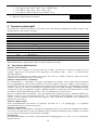
Avvertenze .................................................................................................................................................... 6
Descrizione prodotto ..................................................................................................................................... 6
2.1
Limiti d’impiego................................................................................................................................... 7
3
Installazione .................................................................................................................................................. 7
3.1
Verifiche e preliminari.......................................................................................................................... 7
3.2
Impianto tipico (fig. 3).......................................................................................................................... 8
3.3
Fissaggio............................................................................................................................................... 8
3.4
Allacciamento all’alimentazione .......................................................................................................... 8
3.5
Schema elettrico.................................................................................................................................... 9
3.6
Descrizione dei collegamenti.............................................................................................................. 10
3.7
Note sui Collegamenti elettrici ........................................................................................................... 10
3.8
Tipologia dell’ ingresso Alt ................................................................................................................ 11
3.9
Fototest ............................................................................................................................................... 11
3.10
Verifica dei collegamenti.................................................................................................................... 11
4
Programmazione e regolazioni.................................................................................................................... 12
4.1
Ricerca iniziale degli arresti meccanici .............................................................................................. 12
4.2
Ricerca automatica degli arresti meccanici ........................................................................................ 13
4.3
Programmazione manuale dei rallentamenti....................................................................................... 13
4.4
Procedura di memorizzazione............................................................................................................. 14
4.5
Cancellazione della memoria.............................................................................................................. 14
4.6
Regolazioni......................................................................................................................................... 14
4.6.1 Regolazione forza........................................................................................................................... 14
4.6.2 Regolazione velocità ...................................................................................................................... 15
4.6.3 Regolazione tempo pausa............................................................................................................... 15
5
Collaudo ...................................................................................................................................................... 15
6
Funzioni selezionabili ................................................................................................................................. 16
6.1
Descrizione delle funzioni .................................................................................................................. 16
7
Cosa fare se ................................................................................................................................................. 17
8
Manovra manuale o sblocco........................................................................................................................ 18
9
Manutenzione .............................................................................................................................................. 18
9.1
Pianificazione interventi manutenzione.............................................................................................. 18
10 Smaltimento ................................................................................................................................................ 20
11 Caratteristiche tecniche ............................................................................................................................... 20
11.1
Caratteristiche centrale di comando.................................................................................................... 21
12 Accessori ..................................................................................................................................................... 21
12.1
Ricevitore RADIO .............................................................................................................................. 21
13 Istruzioni ed avvertenze destinate all’utilizzatore della barriera SIGNO.................................................... 22
5
$YYHUWHQ]H
E’ necessario leggere tutte le istruzioni prima di procedere all’ installazione, in quanto forniscono importanti indicazioni
riguardanti la sicurezza, l’ installazione, l’ uso e la manutenzione.
Per rendere più semplice l’ uso di queste istruzioni si è cercato, di rispettare l’ ordine con cui devono essere eseguite le varie
fasi dell’ installazione. Tutto quello che non è espressamente previsto in queste istruzioni non è permesso, usi non previsti
potrebbero essere fonte di danni al prodotto e mettere in pericolo persone e cose.
Conservare questo manuale anche per utilizzi futuri.
La progettazione, la fabbricazione dei dispositivi che compongono SIGNO ed il presente manuale rispettano pienamente
la norma vigente.
Considerando le situazioni di rischio che possono verificarsi durante l’ installazione e l’ uso di SIGNO è necessario che
anche l’ installazione avvenga nel pieno rispetto di leggi, norme e regolamenti; in particolare:
• Prima di iniziare l’ installazione verificare la necessità di ulteriori dispositivi e materiali che possono servire a
completare l’ automazione con SIGNO in base alla specifica situazione d’ impiego.
• L’ automatismo non deve essere utilizzato prima di aver effettuato la messa in servizio come specificato nel
paragrafo: Collaudo e messa in servizio.
• Il materiale dell’ imballaggio deve essere smaltito nel pieno rispetto della normativa locale.
• Non eseguire modifiche su nessuna parte se non previste nel presente manuale. Operazioni di questo tipo possono
solo causare malfunzionamento. NICE declina ogni responsabilità per danni derivati da prodotti modificati.
• Evitare che le parti dell’ automatismo possano venir immerse in acqua o in altre sostanze liquide. Anche durante
l’ installazione evitare che liquidi possano penetrare all’ interno della centrale e di altri dispositivi aperti.
• Qualora sostanze liquide siano penetrate all’ interno dei dispositivi dell’ automatismo, scollegare immediatamente
l’ alimentazione elettrica e rivolgersi al servizio di assistenza NICE; l’ uso di SIGNO in tali situazioni può causare
situazioni di pericolo.
• Non tenere qualsiasi componente di SIGNO vicino a fonti di calore né esporlo a fiamme; tali azioni possono
danneggiarlo ed essere causa di malfunzionamenti, incendio o situazioni di pericolo.
• Nel caso di lunghi periodi di inutilizzo, per evitare il rischio di perdite di sostanze di sostanze nocive dalla batteria
opzionale è preferibile estrarla e custodirla in luogo asciutto.
• Collegare la centrale solo ad una linea di alimentazione elettrica dotata di messa a terra di sicurezza.
• Tutte le operazioni che richiedono l’ apertura della porta di SIGNO devono avvenire con la centrale di comando
scollegata dall’ alimentazione elettrica; se il dispositivo di sconnessione non è a vista apporvi un
cartello:”ATTENZIONE MANUTENZIONE IN CORSO”.
• Qualora si verifichino interventi di interruttori automatici o di fusibili, prima di ripristinarli è necessario
individuare ed eliminare il guasto.
Nel caso di guasto non risolvibile facendo uso delle informazioni riportate nel presente manuale, interpellare il servizio di
assistenza NICE.
'HVFUL]LRQHSURGRWWR
SI GN O è un’ alza barriera stradale elettromeccanica, comprensiva di piastra di fondazione, staffa per attacco asta
rettangolare e centrale di comando.
L’ automazione è in grado di raggiungere i limiti della corsa (apertura e chiusura) attraverso una fase di
rallentamento e di rilevare lo sforzo a cui è sottoposto il motore durante il movimento.
Grazie a questo controllo, eventuali ostacoli lungo la corsa vengono prontamente rilevati con conseguente
inversione del moto (funzione amperometrica). Sono possibili azionamenti in modo "manuale",
"semiautomatico” e "automatico" con funzioni come “Richiudi 0 secondi dopo Foto” , “Richiudi sempre" e due
tipi di segnalazioni semaforiche. La centrale include un contatore di manovre che permette la gestione nel
tempo degli interventi di manutenzione dell’ impianto, ed è predisposta per l'
inserimento dei ricevitori radio con
innesto SM.
In tutte le versioni sono previsti accessori opzionali.
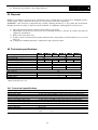
SI GN O 3
SI GN O 4
SI GN O 6
Consente di automatizzare un passaggio con asta di max.3 mt
Consente di automatizzare un passaggio con asta di max.4 mt
Consente di automatizzare un passaggio con asta di max.6 mt
6
/LPLWLG¶LPSLHJR
,QVWDOOD]LRQH
Ricordiamo che gli impianti di cancelli e porte automatiche devono essere installati solo da personale tecnico
qualificato nel pieno rispetto della normativa in vigore. Prima di iniziare l’ installazione seguire attentamente le
istruzioni riportate nel seguente manuale.
9HULILFKHHSUHOLPLQDUL
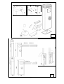
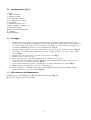
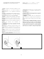
• Verificare che la confezione sia integra.Togliendo il coperchio e la porta, verificare che contenga tutte le parti
presenti in )LJ
N°4Zanche M12
N° 4 Rondelle φ 12
N°4 Dadi M12 Autobl.
N°2 Viti 4.2x9.5
N°1 Staffa supp. Asta
N°1 Coppia di chiavi per sblocco
N°1 Coppia di chiavi per coperchio
N°4VitiM8x16
N°1PiastradiFond.
N°1 Coperchio asta
N°1Tapposerigrafato
N°1Tappoanteriore
•
•
•
•
•
Verificare, facendo riferimento alla )LJ, che la zona di fissaggio sia compatibile con l’ ingombro della barriera.
$WWHQ]LRQH: verificare l’ orientamento dell’ asta, se destro (5) o sinistro (/)
Verificare che durante tutta la manovra di apertura e chiusura , non esistano ostacoli che possano intralciare il
movimento dell’ asta.
Verificare che il basamento di appoggio della SIGNO sia solido ed adeguato.
Verificare che la zona di fissaggio della barriera consenta una manovra manuale facile e sicura.
Verificare che i punti di fissaggio dei vari dispositivi siano in zone protette da urti e le superfici siano
sufficientemente solide.
7
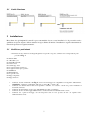
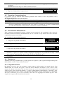
,PSLDQWRWLSLFRILJ
1 . Signo
2 . Asta in alluminio
3 . Selettore a chiave
4 . Colonnina per selettore
5 . Colonnina per fotocellula
6 . Fotocellula
7 . Gomma protettiva rossa
8 . Bordo sensibile o gomma rossa
9 . Luci lampeggianti
10. Strisce rosse catarifrangenti
11. Antenna
12. Lampeggiante
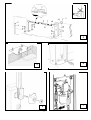
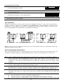
)LVVDJJLR
1.
Annegare la base di ancoraggio in dotazione, in una piazzola di calcestruzzo di adeguate dimensioni. La base
dovrà essere a filo della piazzola, perfettamente in bolla con la superficie in vista ben pulita , facendo attenzione a
non rovinare il filetto delle zanche ed avendo cura di prevedere almeno uno o più condotti per il passaggio dei
cavi elettrici. $WWHQ]LRQH: la piastra deve essere parallela all’ asta.)LJ
2. Appoggiare SIGNO sulla base collocata precedentemente e bloccarlo con le viti e rondelle in dotazione. )LJ
3. Se necessario , invertire la posizione della molla , da destra a sinistra. Attenzione: con molla a riposo l’ asta è
verticale. )LJ
4. Montare l’ asta con l’ apposito attacco in dotazione e bloccare le 4 viti. )LJ
5. Eseguire lo sblocco (vedi capitolo 8)
6. Portare l’ asta in posizione orizzontale ed applicare gli eventuali accessori opzionali .
7. Agendo sul tirante di regolazione della molla , bilanciare l’ asta.. Sarà ben bilanciata quando portata a 45°, non
cadrà verso il basso e non salirà verso l’ alto. )LJ
8. Si può regolare la linearità orizzontale e verticale agendo sui relativi ammortizzatori con fermo )LJ
9. Ribloccare la barriera effettuando l’ operazione contraria al punto 5.
10. Se non si utilizzano o si utilizzano in parte, gli accessori di SIGNO, il bilanciamento può risultare facilitato,
fissando la molla in uno dei fori precedenti )LJ
$OODFFLDPHQWRDOO¶DOLPHQWD]LRQH
Collegare il cavo di alimentazione (230V) direttamente al morsetto. )LJ
Bloccare con l’ apposita fascetta blocca fili.
8
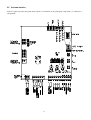
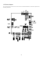
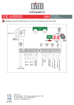
6FKHPDHOHWWULFR
Viene di seguito riportata una pianta della scheda con l’ indicazione dei principali componenti e lo schema dei
collegamenti.
9
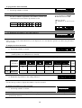
'HVFUL]LRQHGHLFROOHJDPHQWL
1-2
3-4
5-6
7-8
9-10
11
12
Fase - Neutro
Lampeggiante
Elettroblocco/Ventosa
Fototest
24 Vcc
Comune
Sca
=
=
=
=
=
=
=
13
Cor
=
14
15
16
Man
Sinc
Alt
=
=
=
17
Foto
=
18
19
Passo Passo
Apre
=
=
20
Chiude
=
Antenna
Batteria
=
=
Alimentazione da rete
Uscita lampeggiante 24 Vcc max 25W
Uscita elettroblocco/ventosa 24Vcc max 250 mA
Uscita fototest
Alimentazione servizi 24 Vcc massimo 200mA
Comune per tutti gli ingressi
Uscita spia barriera aperta (Spia accesa = barriera aperta; spenta = barriera
chiusa; lampeggia veloce = fase di chiusura; lampeggia lenta = fase di
apertura)
Uscita Luce di cortesia (si attiva all’ inizio di una manovra e rimane attiva
per altri 60 secondi dopo che la manovra stessa è terminata)
Uscita Spia manutenzione
Sincronismo barriere
Ingresso con funzione di ALT (Emergenza, blocco o sicurezza estrema) di
tipo normalmente chiuso (NC) oppure a resistenza costante 8,2KΩ
(paragrafo 0)
Ingresso di tipo NC per dispositivi di sicurezza (Fotocellule, coste
pneumatiche) con intervento nella manovra di chiusura
Ingresso per funzionamento ciclico Apre - Stop - Chiude – Stop
Ingresso per movimento in apertura con funzionamento ciclico Apre- StopApre-Stop
Ingresso per movimento in chiusura con funzionamento ciclico ChiudeStop- Chiude-Stop
Ingresso antenna per il ricevitore radio
Collegamento scheda carica batteria
1RWHVXL&ROOHJDPHQWLHOHWWULFL
Per garantire la sicurezza dell'
operatore e per evitare danni ai componenti, mentre si effettuano i collegamenti o
si innesta il ricevitore radio la centrale deve essere scollegata dalla rete elettrica e da eventuali batterie.
3HUHIIHWWXDUHLFROOHJDPHQWLIDUHULIHULPHQWRDOORVFKHPDHOHWWULFRGHOSDUDJUDIRWHQHQGRSUHVHQWH
FKH
• La centrale va alimentata con un cavo da 3 x 1,5mm2 (fase, neutro e terra); se la distanza fra la centrale
e la connessione all'
impianto di terra supera i 30m è necessario prevedere un dispersore di terra in
prossimità della centrale
• Per il collegamento del lampeggiante e dell’ elettro-blocco si consiglia di usare cavo con sezione
minima di 1mm2
• Nei collegamenti della parte a bassissima tensione di sicurezza usare cavetti di sezione minima pari a
0,25mm2; (usare cavetti schermati se la lunghezza supera i 30m collegando la calza a terra solo dal lato
della centrale).
• Prestare attenzione ai dispositivi con polarità (lampeggiante, elettroblocco, fototest, servizi, ecc).
• Gli ingressi di tipo Normalmente Chiuso (NC), se non usati, vanno ponticellati con il “ Comune 24
Vcc” ; gli ingressi di tipo Normalmente Aperto (NA), se non usati, vanno lasciati liberi.
• I contatti devono essere assolutamente di tipo meccanico e svincolati da qualsiasi potenziale; non sono
ammessi collegamenti a stadi tipo quelli definiti "PNP” , "NPN” , "Open Collector” ecc.
10
7LSRORJLDGHOO¶LQJUHVVR$OW
La centrale può essere programmata per due tipologie di ingresso ALT:
• Alt di tipo NC: per il collegamento di dispositivi con uscita a contatto normalmente chiuso
(impostazione di fabbrica).
• Alt a resistenza costante: permette di collegare dispositivi con uscita a resistenza costante 8,2KΩ (es.
bordi sensibili). In tal caso la centrale misura il valore della resistenza collegata tra l’ ingresso Alt e il
comune dei servizi e toglie il consenso alla manovra quando il valore misurato esce dall’ intervallo
delimitato dal valore 8,2KΩ +/- 50%.
3HUSURJUDPPDUHO¶LQJUHVVR$OW
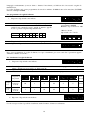
1. Impostare i dip switch come indicato
1 2 3 4 5 6 7 8 9 10
11 12
2. Eseguire la “ procedura di memorizzazione” (paragrafo 4.4) che in questo caso serve per memorizzare in
auto apprendimento lo stato dell’ ingresso Alt.
3. Riportare i dip swich come indicato
1 2 3 4 5 6 7 8 9 10
11 12
1RWD Al termine della programmazione il led alt deve rimanere acceso a conferma della corretta
memorizzazione.
!
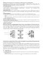
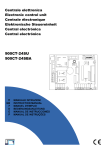
)RWRWHVW
La funzione Fototest è un’ ottima soluzione in termini di affidabilità nei confronti dei dispositivi di sicurezza e
permette di raggiungere, per quanto riguarda l’ insieme centrale e sicurezze, la “ categoria 2” secondo la norma
UNI EN 954-1 (ediz. 12/1998). Per realizzare questa soluzione è necessario collegare le fotocellule come
indicato nella figura seguente e porre il dip switch 7 in On (attivazione fototest).
FOTO
FOTO
Ogni volta che viene avviata una manovra vengono controllati tutti i dispositivi di sicurezza e solo se il test da
esito positivo la manovra ha inizio.
9HULILFDGHLFROOHJDPHQWL
Le prossime operazioni vi porteranno ad agire su circuiti sotto tensione, alcune parti sono sottoposte a tensione
di rete quindi altamente pericolose! Prestate massima attenzione alle operazioni che eseguite e non operate mai
da soli.
7HUPLQDWLLFROOHJDPHQWLqRSSRUWXQRIDUHXQDYHULILFDJHQHUDOHRYYHUR
• Alimentare la centrale e verificare immediatamente che sui morsetti 1-2 ci sia tensione di rete e che sui
morsetti 9-10 (uscita servizi) sia presente una tensione compresa tra 28 e 33 volt. Se i valori non
corrispondono togliere subito l’ alimentazione e verificare con maggiore attenzione i collegamenti e la
11
•
•
•
•
•
tensione di alimentazione.
Dopo circa due secondi dall’ accensione, il led OK deve lampeggiare con cadenza regolare di un secondo
ad indicare il corretto funzionamento della centrale.
Verificare che i led relativi agli ingressi Alt e Foto siano accesi (sicurezze attive) mentre i led relativi agli
ingressi passo passo , apre e chiude siano spenti (nessun comando presente); se questo non avviene
controllare i collegamenti e l'
efficienza dei vari dispositivi
Verificare il corretto funzionamento di tutti i dispositivi di sicurezza presenti nell'
impianto (arresto di
emergenza, fotocellule, coste pneumatiche ecc.), ogni volta che intervengono, il relativi led Alt e Foto
devono spegnersi.
Sbloccare la barriera e verificare che:
l'
asta sia bilanciata, se non lo fosse regolare la molla di bilanciamento
l’ asta si possa muovere senza particolari sforzi per tutta la sua corsa
ci sia corrispondenza dei finecorsa: con l’ asta chiusa deve spegnersi solo il Led fine corsa chiude,
quando è aperta deve spegnersi solo il led fine corsa apre; se non fosse così togliere l’ alimentazione e
invertire il connettore dei finecorsa
lasciare l’ asta a circa 45° in modo che sia libera di muoversi in apertura e chiusura e bloccare la
barriera
Verificare che il movimento dell’ asta avvenga nella giusta direzione, ovvero:
premere il tastino Chiude e verificare che l’ asta si muova nel senso di chiusura
se la manovra eseguita è di apertura, premere nuovamente sul tastino chiude per fermare il moto,
togliere l’ alimentazione e invertire i due fili del motore
indipendentemente dal verso del movimento è opportuno fermare subito la manovra premendo
nuovamente il tastino Chiude
3URJUDPPD]LRQHHUHJROD]LRQL
Se la verifica dei collegamenti ha dato esito positivo, si può dare inizio alla fase di ricerca degli arresti
meccanici. L’ operazione è necessaria perché la centrale SIA20 deve misurare lo spazio percorso dal
motoriduttore, per portare l’ asta dalla posizione di massima chiusura (posizione 0) a quella di massima apertura
(posizione 1).
La ricerca degli arresti meccanici può avvenire attraverso la ricerca iniziale o la ricerca automatica.
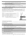
Dopo la “ ricerca iniziale ” o la “ ricerca automatica” , se si desidera si possono modificare, attraverso la
programmazione manuale, le posizioni di rallentamento RA e RC.
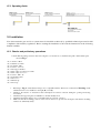
1
RA
Posizione
0: è il punto in cui l’ asta si trova nella situazione di chiusura,
corrispondente con l'
arresto meccanico in chiusura.
Posizione RC: è la posizione in cui si desidera che l’ asta inizi a rallentare nella
manovra di chiusura.
Posizione RA: è la posizione in cui si desidera che l’ asta inizi a rallentare nella
manovra di apertura.
Posizione 1: è il punto in cui l’ asta si trova nella situazione di massima
apertura, corrispondente con l’ arresto meccanico in apertura.
RC
0
5LFHUFDLQL]LDOHGHJOLDUUHVWLPHFFDQLFL
La procedura "ricerca iniziale degli arresti meccanici” viene eseguita automaticamente come prima manovra
dopo l’ installazione.
3HUDWWLYDUHODULFHUFDLQL]LDOHGHJOLDUUHVWLPHFFDQLFL
1. sbloccare la barriera, allontanare l’ asta dai fermi meccanici in modo che sia libera di muoversi in apertura
e chiusura, bloccare la barriera
12
2. premere brevemente il tastino Chiude presente sulla scheda oppure dare un impulso di comando sugli
ingressi e attendere che la centrale esegua una chiusura lenta fino alla posizione 0, un’ apertura lenta fino
alla posizione 1 e una chiusura veloce fino alla posizione 0.
1RWD se dopo il comando la prima manovra è un’ apertura, dare un altro comando per fermare la procedura
e invertire la polarità del motore.
3. Terminata la sequenza descritta prima, con una operazione matematica vengono automaticamente
calcolate le posizioni di rallentamento (quote RA e RC).
4. La procedura di "ricerca iniziale" degli arresti meccanici è conclusa e il motoriduttore è pronto all'
uso.
Impostare i dip switch “ funzioni” nel modo desiderato.
1RWD Se durante la "ricerca iniziale delle quote" c’ è un intervento di uno dei dispositivi di sicurezza
oppure un altro impulso di comando, il movimento dell’ asta verrà immediatamente arrestato; sarà quindi
necessario ripetere le operazione sopra descritte partendo dal punto 1.
5LFHUFDDXWRPDWLFDGHJOLDUUHVWLPHFFDQLFL
In alternativa alla “ Ricerca iniziale” è possibile in qualsiasi momento attivare la “ Ricerca automatica degli
arresti meccanici” senza necessariamente cancellare la memoria. La procedura esegue automaticamente la
ricerca degli arresti meccanici (posizione 0 e 1) con la stessa modalità descritta nella “ Ricerca Iniziale” .
3HUDWWLYDUHODULFHUFDGHJOLDUUHVWLPHFFDQLFL
1. Impostare i Dip Switch nel seguente modo:
1 2 3 4 5 6 7 8 9 10
11 12
2. sbloccare la barriera, allontanare l’ asta dai fermi meccanici in modo che sia libera di muoversi in apertura
e chiusura, bloccare la barriera
3. premere brevemente il tastino Chiude sulla scheda e attendere che la centrale esegua una chiusura lenta
fino alla posizione 0, un’ apertura lenta fino alla posizione 1 e una chiusura veloce fino alla posizione 0.
1RWD se dopo il comando la prima manovra è un’ apertura, dare un altro comando per fermare la procedura
e invertire la polarità del motore.
4. Terminata la sequenza descritta prima, con una operazione matematica vengono automaticamente
calcolate le quote necessarie per i rallentamenti.
5. Riportare i Dip Switch nel seguente modo:
1 2 3 4 5 6 7 8 9 10
11 12
6. La procedura di "ricerca automatica " degli arresti meccanici è conclusa e il motoriduttore è pronto all'
uso.
Impostare i dip switch “ funzioni” nel modo desiderato.
1RWD Se durante la "ricerca iniziale delle quote" c’ è un intervento di uno dei dispositivi di sicurezza
oppure un altro impulso di comando, la manovra verrà immediatamente arrestato, sarà quindi necessario
ripetere le operazione sopra descritte partendo dal punto 1.
3URJUDPPD]LRQHPDQXDOHGHLUDOOHQWDPHQWL
La procedura prevede l’ inserimento manuale delle posizioni di inizio rallentamento in alternativa a quelle
calcolate in automatico con la ricerca iniziale o automatica degli arresti meccanici.
3HUSURJUDPPDUHPDQXDOPHQWHLUDOOHQWDPHQWL
Impostare i dip switch in uno dei modi sotto indicati a seconda del parametro da memorizzare
326,=,21( 5& Posizione in cui ha inizio il rallentamento nella
manovra di chiusura
326,=,21( 5$ Posizione in cui ha inizio il rallentamento nella
manovra di apertura
13
1 2 3 4 5 6 7 8 9 10
11 12
1 2 3 4 5 6 7 8 9 10
11 12
2. Premere e tenere premuto il tasto Apre o Chiude sulla scheda fino al raggiungimento della posizione
desiderata.
1RWD Premere il tasto Stop se si desidera accelerare il moto.
3. Raggiunta la posizione, rilasciare i tasti ed eseguire la “ Procedura di memorizzazione” paragrafo 4.4)
4. Riportare i Dip Switch nel seguente modo:
1 2 3 4 5 6 7 8 9 10
11 12
3URFHGXUDGLPHPRUL]]D]LRQH
L’ operazione serve per trasferire nella memoria permanente della centrale, il valore del parametro che si
desidera programmare.
3HUHVHJXLUHODSURFHGXUDGLPHPRUL]]D]LRQH
1. Premere per almeno 3 s il tasto Stop, trascorsi i 3 s il led OK lampeggia velocemente
2. Togliere l'
azione sul tasto Stop, il led OK continua a lampeggiare velocemente per altri 3 s.
3. Entro tre secondi premere contemporaneamente e VROR SHU XQ LVWDQWH i due tasti apre e chiude; alla
pressione contemporanea dei due tasti il led ok si spegne e si accende per 2 s circa a conferma che la
procedura di memorizzazione del parametro selezionato è avvenuta correttamente.
&DQFHOOD]LRQHGHOODPHPRULD
Tutti i parametri programmabili vengono registrati in una memoria di tipo permanente che conserva le
informazioni anche in mancanza dell’ alimentazione da rete; in alcuni casi può rendersi necessario cancellare
completamente quanto memorizzato.
3HUFDQFHOODUHLOFRQWHQXWRGHOODPHPRULD
1. Impostare i dip switch come indicato:
1 2 3 4 5 6 7 8 9 10
11 12
2. Eseguire la “ procedura di memorizzazione” (paragrafo 4.4) che in questo caso serve per confermare la
cancellazione.
3. Riportare i dip switch come indicato
1 2 3 4 5 6 7 8 9 10
11 12
1RWD Con la memoria azzerata è come se la centrale non fosse mai stata installata e quindi non sarà possibile il
movimento; in questo caso il primo comando che giungerà sugli ingressi o la pressione dei tasti Apre o Chiude
andrà ad attivare immediatamente una procedura di "Ricerca iniziale delle quote"
1RWD Con questa operazione non viene cancellato il numero delle manovre eseguite e il numero di manovre
programmate.
5HJROD]LRQL
Terminata la fase di programmazione è possibile passare ad eseguire le poche regolazioni indispensabili per un
funzionamento corretto e sicuro dell’ automazione.
5HJROD]LRQHIRU]D
Per limitare le forze in gioco nel movimento, requisito imposto dalle normative, la centrale dispone di un
Trimmer TR1 che consente di regolare la forza del motore. Ruotando il trimmer in senso orario la forza
aumenta. Se durante il movimento dell’ asta viene rilevato un ostacolo (forza richiesta dal motore maggiore di
quella regolata), viene eseguita una fermata e, se è attivo il funzionamento semiautomatico o automatico, viene
avviata una manovra nel verso opposto. Per aumentare ulteriormente il livello di sicurezza, se la rilevazione
dell’ ostacolo interviene per tre volte consecutive senza che l’ asta raggiunga una chiusura regolare, viene
eseguito uno stop preceduto da una breve inversione.
14
5HJROD]LRQHYHORFLWj
Per limitare l’ energia cinetica dell’ asta contro un eventuale ostacolo, oltre alla limitazione della forza del
motore si può ridurne la velocità. La regolazione della velocità può essere fatta in qualsiasi momento agendo
sul trimmer TR2: ruotando il trimmer in senso orario la velocità aumenta. Con il trimmer al massimo si ha un
tempo di apertura di circa 3 s, con il trimmer al minimo il tempo di apertura è di circa 6 s.
5HJROD]LRQHWHPSRSDXVD
Quando viene selezionata la funzione di chiusura automatica, dopo una manovra di apertura viene attivato un
temporizzatore (tempo pausa), allo scadere del quale si attiva automaticamente una manovra di chiusura. Il
tempo pausa è regolabile attraverso il trimmer TR3. Con il Trimmer al minimo la pausa è di 0 s, con il trimmer
al massimo (rotazione oraria) la pausa è di 120 s.
&ROODXGR
Queste sono le fasi più importanti nella realizzazione dell’ automazione al fine di garantire la massima
sicurezza.Il collaudo può essere usato anche come verifica periodica dei dispositivi che compongono
l’ automatismo.
Il collaudo dell’ intero impianto deve essere eseguito da personale esperto e qualificato che deve farsi carico
delle prove richieste, in funzione del rischio presente e di verificare il rispetto di quanto previsto da leggi,
normative e regolamenti, ed in particolare tutti i requisiti della norma EN12445 che stabilisce i metodi di prova
per la verifica degli automatismi con barriere stradali a transito misto, veicoli e pedoni.
Ogni singolo componente, ad esempio arresto di emergenza, fotocellule ecc. può richiedere una specifica fase
di collaudo e per questo si consiglia di seguire le procedure riportate nei rispettivi manuali istruzioni.
3HULOFROODXGRHVHJXLUHODVHTXHQ]DGLRSHUD]LRQL
Verificare che sia rispettato rigorosamente quanto previsto nel capitolo “ AVVERTENZE” .
2. Impostare i Dip Switch come indicato:
(tutte le funzioni disattivate e funzionamento semiautomatico)
1 2 3 4 5 6 7 8 9 10
11 12
1. Premere e il tasto Apre e verificare che:
• si attivi il lampeggiante
• parta una manovra di apertura con la fase di accelerazione
• il movimento si arresti, preceduto dalla fase di rallentamento, quando l’ asta è aperta.
2. Premere il tasto Chiude e verificare che
• si attivi il lampeggiante
• parta una manovra di chiusura
• il movimento si arresti, con l’ asta chiusa.
3. Far partire una manovra di apertura e verificare che l’ intervento di un dispositivo collegato all’ ingresso
• Alt, provochi l’ arresto immediato del movimento
• Foto, non abbia nessun effetto
4. Far partire una manovra di chiusura e verificare che l’ intervento di un dispositivo collegato all’ ingresso
• Alt, provochi l’ arresto immediato del movimento
• Foto, provochi la fermata e l’ inversione della manovra
5. Impegnare un dispositivo collegato all’ ingresso:
• Alt, e verificare che attivando un ingresso di comando non parta nessuna manovra
• Foto, e verificare che attivando un ingresso di comando che provoca una chiusura non parta la manovra
6. Durante una manovra, sia in apertura che in chiusura, impedire il movimento della asta con un ostacolo e
verificare che avvenga un’ inversione prima di superare la forza prevista dalle normative.
7. Eseguire la misura della forza d’ impatto secondo quanto previsto dalla norma EN 12445 ed eventualmente,
se il controllo della “ forza motore” viene usato come ausilio al sistema per la riduzione della forza di
impatto, provare a trovare la regolazione che dia migliori risultati
15
8. Verificare che l’ attivazione degli ingressi (se collegati) provochi un passo nella sequenza
• per l’ ingresso Passo-Passo: Apre – Stop – Chiude –Stop,
• per l’ ingresso Apre: Apre – Stop – Apre – Stop,
• per l’ ingresso Chiude: Chiude - Stop- Chiude – Stop
9. Riportare i dip switch come indicato
1 2 3 4 5 6 7 8 9 10
11 12
)XQ]LRQLVHOH]LRQDELOL
Per selezionare le funzioni desiderate è necessario porre i dip switch programmazione in Off, e attivare i dip
switch funzioni come elencato di seguito:
Switch 1-2
Switch 3
Switch 4
Switch 5
Switch 6
Switch 7
Switch 8
Switch 9
Switch 10
Off Off
On Off
Off On
On On
On
On
On
On
On
On
Off
On
On
=
=
=
=
=
=
=
=
=
=
=
=
=
Funzione “ Manuale” cioè Uomo Presente
Funzione “ Semiautomatico”
Funzione “ Automatico” cioè Chiusura Automatica
Funzione “ Automatico + Chiude sempre”
Funzione condominiale <Non disponibile in modo Manuale>
Prelampeggio 5 s.(2 s. se in manuale)
Richiudi 0 s dopo Foto se in automatico o richiudi dopo Foto se semiautomatico
Foto anche in apertura
Attivazione Fototest
Ventosa
Elettroblocco
Semaforo in modalità a senso unico
Semaforo nei due sensi
1RWDNaturalmente ogni Switch in "Off" non attiva la funzione descritta.
'HVFUL]LRQHGHOOHIXQ]LRQL
)XQ]LRQH8RPR3UHVHQWH
Il movimento viene eseguito solo alla presenza del comando. La manovra si arresta non appena cessa il
comando oppure dopo un intervento di un dispositivo di sicurezza (“ Alt” o “ Foto” ) o di un intervento
dell’ amperometrica.
Una volta che la manovra si è arrestata è necessario far cessare il comando in ingresso prima che un altro
comando possa far iniziare un nuovo movimento.
)XQ]LRQHVHPLDXWRPDWLFRHDXWRPDWLFR
In "Semiautomatico" o “ Automatico” , in seguito ad un impulso di comando, viene eseguito tutto il movimento
fino al raggiungimento della posizione prevista. Un secondo impulso sullo stesso ingresso che ha iniziato il
movimento provoca uno Stop. Se in un ingresso di comando, invece di un impulso, viene mantenuto un segnale
continuo, si provoca uno stato di prevalenza in cui gli altri ingressi di comando rimangono disabilitati (utile per
collegare un orologio in apertura per esempio). Durante una manovra l’ intervento dell’ amperometrica o di una
fotocellula coinvolta nella direzione del moto (“ Foto” in chiusura) provoca l’ inversione.
Nel modo di funzionamento Automatico, dopo una apertura viene eseguita una pausa e quindi una chiusura. Se
durante la pausa vi fosse un intervento di “ Foto” , il temporizzatore verrà ripristinato con il tempo pausa
regolato; se invece durante la pausa interviene l’ ingresso “ Alt” , la funzione di richiusura viene cancellata e si
passa in uno stato di Stop.
)XQ]LRQH&KLXGH6HPSUH
Avvia automaticamente una manovra di chiusura, preceduta da 5 s di prelampeggio, se al ripristino
dell’ alimentazione viene rilevata l’ asta aperta.
)XQ]LRQH&RQGRPLQLDOH
Nel funzionamento “ Condominiale” , una manovra di apertura non può essere interrotta da impulsi di comando,
ad eccezione di quelli che provocano una chiusura. Nel movimento in chiusura un nuovo impulso di comando
provoca l'
arresto e l'
inversione del movimento in apertura.
3UHODPSHJJLR
In seguito ad un impulso di comando, viene prima attivato il lampeggiante e poi, dopo 5 s (2 s se in manuale),
inizia la manovra.
16
5LFKLXGLVHFRQGLGRSR)RWRVHLQDXWRPDWLFRRULFKLXGLGRSR)RWRVHVHPLDXWRPDWLFR
In automatico, un intervento di foto nella manovra di apertura o chiusura riduce il tempo pausa a 0 s
indipendentemente dal tempo pausa regolato. In semiautomatico, un intervento di foto nella manovra di
chiusura attiva la chiusura automatica con il tempo pausa regolato.
)RWRDQFKHLQDSHUWXUD
Con questa funzione l'
intervento del dispositivo di sicurezza “ Foto” provoca una interruzione del movimento
anche in apertura; se selezionata la funzione “ Semiautomatico” o “ Automatico” , dopo il disimpegno della
“ Foto” si avrà la ripresa del moto in apertura.
$WWLYD]LRQH)RWRWHVW
Questa funzione permette di eseguire all’ inizio di ogni manovra un controllo dell’ efficienza di tutte le
fotocellule, aumentando in questo modo la sicurezza dell’ impianto. Per maggiori dettagli consultare il paragrafo
3.9.
9HQWRVDHOHWWUREORFFR
La funzione permette di assegnare all’ uscita Elettroblocco (morsetti 5 e 6) un funzionamento di tipo:
• elettroblocco (Switch 8 Off) - l’ uscita si attiva per qualche secondo nella manovra di apertura con l’ asta
chiusa
• ventosa (Switch 8 On) - l’ uscita si attiva al termine del movimento di chiusura e rimane attiva per tutto il
tempo in cui l’ asta è chiusa.
6HPDIRURLQPRGDOLWjDVHQVRXQLFR
In questa modalità l’ uscita SCA è attiva con l’ asta aperta e durante la manovra di apertura rimane accesa,
mentre si disattiva nella manovra di chiusura
e ad asta chiusa. In questo modo può essere applicata all’ uscita una lampada di colore verde che, se accesa, sta
ad indicare passaggio libero.
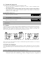
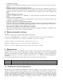
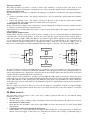
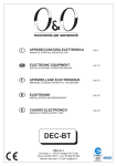
6HPDIRURQHLGXHVHQVL
Ponendo lo switch 10 in On, indipendentemente dallo switch 9, si attiva la funzione “ semaforo nei due sensi” ;
nella centrale avvengono i seguenti mutamenti: l’ ingresso “ Apre” diventa “ Passo Passo2” , mentre le due uscite
“ Luce di Cortesia” (COR) e “ Spia barriera aperta” (SCA) diventano luce verde per un senso e luce verde per
l’ altro come indicato nella Fig. 5. Per ogni senso di marcia viene posto un comando diverso per l’ apertura:
“ Passo Passo” (PP) per entrare e “ Passo Passo 2” (PP2) per uscire; quindi vengono installati due semafori con
segnalazione Rosso e Verde collegate alle uscite SCA e COR.
Ingresso Comando con PP
R
R
V
V
Uscita spia barriera aperta - SCA
(SCA) 12
Barriera
Uscita luce di cortesia - COR
(COR) 13
R
R
V
V
Uscita Comando con PP2
11
Comune
Normalmente le due uscite SCA e COR sono spente e di conseguenza lo sono anche i semafori; quando viene
dato un comando con PP per entrare si avvia la manovra di apertura e contemporaneamente si attiva la SCA che
accende la luce verde in entrata e luce rossa in uscita.
Se invece il comando per l’ apertura viene dato da PP2 si attiva l’ uscita COR che attiva la luce verde in uscita e
luce rossa in entrata. La luce rimarrà accesa per tutta la fase di apertura e per l’ eventuale fase di pausa; nella
fase di chiusura invece verranno attivate contemporaneamente le luci verdi e rosse insieme per indicare che non
c’ è più priorità nel passaggio.
Le due uscite possono comandare direttamente piccole lampade a 24 Vcc per un totale massimo per uscita di 10
W. Nel caso sia necessario usare lampade con potenza maggiore sarà opportuno usare dei relè pilotati dalle
uscite della centrale che comandano a loro volta le lampade del semaforo.
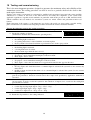
&RVDIDUHVH
Vengono di seguito riportati alcuni dei problemi più comuni che si possono presentare durante l’ installazione.
• 1HVVXQOHGDFFHVR
verificare che sui morsetti 1 e 2 ci sia la tensione di rete e che i fusibili F1 o F3 non siano interrotti.
17
•
•
•
•
•
•
/DPDQRYUDQRQSDUWH
verificare che i led degli ingressi sicurezze Alt e Foto siano attivi e che il motore sia bloccato (led sblocco
spento).
'XUDQWHODPDQRYUDYLHQHHVHJXLWDXQ¶LQYHUVLRQH
Controllare che non ci sia stato un intervento dei dispositivi di sicurezza (foto in chiusura) oppure che non
ci sia stato un intervento dell’ amperometrica; in quest’ ultimo caso verificare che la regolazione fatta sia
sufficiente per il moto dell’ asta. Se non lo è aumentare il livello ruotando in senso orario il trimmer forza
(TR1).
,OOHG2NODPSHJJLDYHORFHPHQWH
la tensione di alimentazione non è sufficiente o è stata selezionata con i Dip switch una combinazione
errata.
,OPRWRUHVLPXRYHOHQWDPHQWH
la centrale sta eseguendo un’ operazione di allineamento; il primo intervento dell’ amperometrica viene
considerato come arresto meccanico.
,OPRWRUHHVHJXHODIDVHGLDFFHOHUD]LRQHHVLIHUPD
controllare se il Led encoder lampeggia durante il movimento del motore. La frequenza del lampeggio può
essere più o meno alta a seconda della velocità del movimento. A motore fermo il led può essere acceso o
spento, a seconda del punto in cui si è fermato l’ albero motore.
/HG2NILVVRSHUTXDOFKHVHFRQGRVXELWRGRSRXQFRPDQGR
indica che c’ è un anomalia nello stadio di comando del motore; verificare il cablaggio e l’ isolamento verso
terra del motore, se tutto è apposto sostituire la centrale.
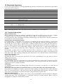
0DQRYUDPDQXDOHRVEORFFR
$WWHQ]LRQHORVEORFFRGHYHDYYHQLUHHVFOXVLYDPHQWHFRQDVWDIHUPD
L’ operazione manuale )LJsi deve eseguire nel caso di mancanza di corrente o in caso di anomalie dell’ impianto.
Consente una corsa libera dell’ asta solo se montato correttamente e con gli accessori originali.
1. Alzare il dischetto copri serratura. Inserire e ruotare la chiave in senso orario
2. Ruotare la maniglia di sblocco in senso antiorario. Muovere manualmente l’ asta
Per bloccare: riportare la maniglia nella posizione di partenza, ruotare la chiave ed estrarla.
0DQXWHQ]LRQH
La manutenzione deve essere effettuata nel pieno rispetto delle prescrizioni sulla sicurezza del presente
manuale e secondo quanto previsto dalle leggi e normative vigenti. Signo non necessita di manutenzioni
particolari, ma un controllo programmato permette una maggiore vita all’ impianto e un sicuro funzionamento
dei sistemi di sicurezza. A tale scopo eseguire per intero le prove e le verifiche previste nel paragrafo 4.1
“ Collaudo” .
Se sono previsti altri dispositivi seguire quanto previsto nel rispettivo piano manutenzione.
6,*12
6,*12
6,*12
Si raccomanda un controllo generale periodico ogni 50.000 cicli
Si raccomanda un controllo generale periodico ogni 6 mesi o 50.000 cicli
Si raccomanda un controllo generale periodico ogni 6 mesi o 50.000 cicli
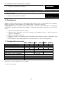
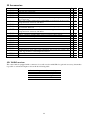
3LDQLILFD]LRQHLQWHUYHQWLPDQXWHQ]LRQH
Per pianificare degli interventi di manutenzione dell’ intero impianto è stato introdotto nella centrale un
contatore di manovre che incrementa il proprio valore ad ogni apertura. L’ incremento è segnalato con un
lampeggio della spia manutenzione (MAN). Il valore del contatore di manovre viene costantemente confrontato
con una soglia di allarme (programmabile dall’ installatore) e con la soglia di guardia (posta automaticamente
pari alla soglia di allarme meno il 6 % circa). Quando il numero delle manovre eseguite supera la soglia di
guardia la spia manutenzione lampeggia solo durante la manovra, mentre, se supera la soglia di allarme
18
lampeggia continuamente (a motore fermo e durante il movimento) ad indicare che è necessario eseguire la
manutenzione.
La soglia di allarme può essere programmate da un valore minimo di 1000 ad una valore massimo di 255000
manovre a multipli di 1000.
3HUSURJUDPPDUHODVRJOLDGLDOODUPH
1. Impostare i dip switch come indicato
1 2 3 4 5 6 7 8 9 10
(VHPSLR numero manovre da
programmare 100.000
Risultato dopo la divisione: 100
2. Dividere il numero delle manovre da programmare per 1000
3. Individuare la nella tabella sotto la combinazione di dip
switch la cui somma dei pesi è uguale al numero appena
trovato e portare i rispettivi dip switch in On.
Dip switch
Pesi
100 = 4+ 32+64
dip switch 3, 6 e 7 in On
Sw1 Sw2 Sw3 Sw4 Sw5 Sw6 Sw7 Sw8
1
2
4
8
16
32
64
11 12
128
1 2 3 4 5 6 7 8 9 10
11 12
1 2 3 4 5 6 7 8 9 10
11 12
4. Eseguire la “ Procedura di memorizzazione” (paragrafo 4.4).
5. Riportare i dip switch come indicato
Dopo aver programmato la soglia di allarme, la si può visualizzare per essere certi che l’ operazione appena
effettuata è andata a buon fine.
3HUYLVXDOL]]DUHODVRJOLDGLDOODUPH
1. Impostare i dip switch come indicato:
1 2 3 4 5 6 7 8 9 10
11 12
2. Porre i dip switch 1 in On (2,3,4,5 e 6 in Off), contare il numero di lampeggi del led ok e riportare il
numero di lampeggi su un foglio (se 10 riportare 0)
3. Ripetere l’ operazione con i dip switch 2, 3, 4, 5 e 6
4. Ricostruire il numero delle manovre come indicato in uno dei due esempi riportati sotto
Configurazione
Dip switch
1 2 3 4 5 6
1 2 3 4 5 6
1 2 3 4 5 6
1 2 3 4 5 6
1 2 3 4 5 6
1 2 3 4 5 6
Numero
Manovre
Esempio
n° 1
Numero
lampeggi
Led ok
10
1
2
10
4
5
012.045
Esempio
n° 2
Numero
lampeggi
Led ok
1
4
10
10
7
3
140.073
6. Riportare i dip switch come indicato
1 2 3 4 5 6 7 8 9 10
Con la stessa procedura è possibile visualizzare anche il numero di manovre effettuate;
19
11 12
3HUYLVXDOL]]DUHLOQXPHURGHOOHPDQRYUHHIIHWWXDWH
1. Impostare i dip switch come indicato:
1 2 3 4 5 6 7 8 9 10
11 12
2. Ripetere il conteggio lampeggi del led ok con i dip switch 1,2,3,4,5 e 6come riportato nell’ esempio 1 o 2.
1RWD Ogni volta che viene programmata la soglia di guardia viene automaticamente cancellato il numero di
manovre eseguite.
Riportare i dip switch come indicato
1 2 3 4 5 6 7 8 9 10
11 12
6PDOWLPHQWR
SIGNO è costituito da diverse tipologie di materiali, alcuni di questi possono essere riciclati (acciaio, alluminio,
plastica, cavi elettrici), altri dovranno essere smaltiti (schede e componenti elettronici).
$77(1=,21(: alcuni componenti elettronici potrebbero contenere sostanze inquinanti, non disperderli
nell’ ambiente. Informatevi sui sistemi di riciclaggio o smaltimento attenendovi alle norme in vigore a livello
locale.
1. Staccare l’ automatismo dalla rete elettrica.
2. Smontare tutti i dispositivi ed accessori, seguendo il procedimento inverso a quello descritto nel
capitolo 3 “ installazione”
3. Rimuovere la scheda elettronica.
4. Smistare ed affidare i vari materiali elettrici e riciclabili a ditte abilitate al recupero e smaltimento degli
stessi.
5. La rottamazione delle restanti strutture deve avvenire attraverso i centri di raccolta previsti.
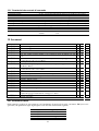
&DUDWWHULVWLFKHWHFQLFKH
Alimentazione (Vac 50/60 Hz)
Alimentazione di emergenza(Vdc)
Potenza assorbita (W)
Assorbimento in linea (A)
Assorbimento motore (A)
Rapporto di riduzione
Coppia (Nm)
Tempo di apertura min÷max. (sec.)
Temperatura di esercizio (C° Min/Max)
Ciclo di lavoro (%)
Grado di protezione (IP)
Peso (Kg)
Classe di isolamento
230
1.1
250
110
230
2.2
1.3
10
1/123
130
1.8* ÷ 4
50
Tutte le Signo sono disponibili anche in versione INOX
* Senza accessori installati
20
24
110
2.6
200
3÷6
20°÷ +50°
80
44
1
300
12
1/241
230
110
1.3
2.6
250
6 ÷ 10
58
&DUDWWHULVWLFKHFHQWUDOHGLFRPDQGR
Uscita servizi
Uscita lampeggiante
Uscita elettroblocco
Uscita fototest
Uscita luce cortesia
Uscita spia barriera aperta
Uscita spia manutenzione
Ingresso ALT :
Tempo pausa
Tempo luce di cortesia
Lunghezza max cavi
:
:
:
:
:
:
:
:
:
:
:
:
24 Vcc, corrente massima 200mA (la tensione può andare da 17 a 35 Vcc)
24 Vcc, potenza massima 25W (la tensione può andare da 16 a 35 Vcc)
24 Vcc corrente massima 250mA (la tensione può andare da 17 a 35 Vcc)
24 Vcc corrente massima 200mA (la tensione può andare da 17 a 35 Vcc)
24 Vcc, potenza massima 10W (la tensione può andare da 17 a 35 Vcc)
24 Vcc, potenza massima 10W (la tensione può andare da 17 a 35 Vcc)
24 Vcc, potenza massima 10W (la tensione può andare da 17 a 35 Vcc)
per contatti NC oppure a resistenza costante 8,2KΩ. +/- 50%
da 0 secondi a 120 secondi
60 secondi
alimentazione
30 m
antenna
5m
$FFHVVRUL
6,$
6,$
6,$
:$
:$
:$
:$
:$
:$
:$
:$
:$
:$
:$
:$
:$
:$
:$
:$
36
6,$
6,*12 ♦
Base di ancoraggio con zanche
Base di ancoraggio con zanche
Asta in alluminio verniciato 36x73x3250 mm
Asta in alluminio verniciato 36x73x4250 mm
Conf. 8m gomma protettiva antiurto rossa completa di tappi di chiusura per asta
WA1
Asta in alluminio tubolare verniciato bianco φ70x4250mm, per applicazioni in
presenza di forte vento solo con WA11
Attacco per asta WA3
Confezione 12 m gomma protettiva antiurto rossa completa di tappi di chiusura per
asta WA21, WA22
Asta in alluminio tubolare verniciato bianco φ90x6250 mm per applicazioni in
presenza di forte vento, solo co Wa11
Attacco per asta WA7
Conf. led di segnalazione ad intermittenza, cablati per aste WA1, WA21,WA22
Strisce rosse adesive catarifrangenti
Appoggio regolabile per aste
Appoggio mobile per aste
Rastrelliera in alluminio da2 m per aste WA1, WA21, WA22.
Snodo per aste WA1 (da 1850mm a 2400mm)
Asta in alluminio verniciato 36x73x6250 mm
Asta componibile , con giunto di unione,in alluminio verniciato 36x94x3125 mm
bianco
Asta tubolare telescopica in alluminio verniciato bianco, lunchezza max. 8m,
completa di appoggio mobile WA12, contrappeso e attacco.
Batteria tampone 24Vdc
Centrale di ricambio
♦
♦
♦
♦
♦
♦
♦
♦
♦
♦
♦
♦
♦
♦
♦
♦
♦
♦
♦
♦
♦
♦
♦
♦
♦
♦
♦
♦
♦
♦
♦
♦
♦
♦
5LFHYLWRUH5$',2
Nella centrale è predisposto un connettore per l’ inserimento di un ricevitore radio con innesto SM (accessorio
opzionale) che permette di agire sugli ingressi come descritto nella tabella seguente:
Uscita Ricevitore
N° 1
N° 2
N° 3
N° 4
Ingresso centrale
Passo Passo
Alt
Apre
Chiude
21
,VWUX]LRQLHGDYYHUWHQ]HGHVWLQDWHDOO¶XWLOL]]DWRUHGHOODEDUULHUD6,*12
Complimenti per aver scelto per la vostra automazione un
prodotto
Nice!
Nice S.p.a. produce componenti per l’automazione di cancelli,
porte,
serrande, tapparelle e tende da sole: motoriduttori, centrali di
comando,
radiocomandi, lampeggianti, fotocellule e accessori.
Nice utilizza solo materiali e lavorazioni di qualità, e per vocazione
ricerca
soluzioni innovative che semplifichino al massimo l’utilizzo delle sue
apparecchiature, curate nelle soluzioni tecniche, estetiche,
ergonomiche:
nella grande gamma Nice il vostro installatore avrà senz’altro
scelto
il prodotto più adatto alle vostre esigenze.
Un impianto di automazione è una bella comodità, oltre che un
valido
sistema di sicurezza e, con poche, semplici attenzioni, è destinato a
durare negli anni.
Anche se l’automazione in vostro possesso soddisfa il livello di
sicurezza
richiesto dalle normative, questo non esclude l’esistenza di un
“rischio
residuo”, cioè la possibilità che si possano generare situazioni di
pericolo,
solitamente dovute ad un utilizzo incosciente o addirittura errato,
per
questo motivo desideriamo darvi alcuni consigli sui comportamenti
da
seguire per evitare ogni inconveniente:
Nice non è però il produttore della vostra automazione, che è
invece il
risultato di un’opera di analisi, valutazione, scelta dei materiali, e
realizzazione
dell’impianto eseguita dal vostro installatore di fiducia.
Ogni automazione è unica e solo il vostro installatore possiede
l’esperienza
e la professionalità necessarie ad eseguire un impianto secondo
le vostre esigenze, sicuro ed affidabile nel tempo, e soprattutto a
regola
d’arte, rispondente cioè alle normative in vigore.
• Prima di usare per la prima volta l’automazione, fatevi spiegare
dall’ installatore l’ origine dei rischi residui, e dedicate qualche
minuto alla lettura del manuale di istruzioni ed avvertenze per
l’utilizzatore consegnatovi dall’ installatore. Conservate il manuale
per ogni dubbio futuro e consegnatelo ad un eventuale nuovo
proprietario
dell’ automazione.
22
diventare
pericoloso:
non
comandate
il
movimento
dell’ automazione
se nel suo raggio di azione si trovano persone, animali o cose.
• La vostra automazione è un macchinario che esegue fedelmente
i vostri comandi; un uso incosciente ed improprio può farlo
• Bambini: un impianto di automazione garantisce un alto
• Anche se ritenete di saperlo fare, non modificate l’ impianto
ed i parametri
di programmazione e di regolazione dell’ automazione: la
responsabilità
è del vostro installatore.
• Il collaudo finale, le manutenzioni periodiche e le eventuali
riparazioni devono essere documentate da chi le esegue e i
documenti conservati
dal proprietario dell’ impianto.
• Smaltimento: Al termine della vita dell’ automazione,
assicuratevi
che lo smantellamento sia eseguito da personale qualificato e
che i
materiali vengano riciclati o smaltiti secondo le norme valide a
livello
locale.
• In caso di rotture o assenza di alimentazione: Attendendo
l’ intervento del vostro installatore, o il ritorno dell’ energia
elettrica se l’ impianto non è dotato di batterie tampone,
l’ automazione può essere azionata come una qualunque
apertura non automatizzata. Per fare ciò è necessario eseguire
lo sblocco manuale (unico intervento consentito all’ utente
sull’ automazione): tale operazione è stata particolarmente
studiata da Nice per assicurarvi sempre la massima facilità di
utilizzo, senza uso di attrezzi o necessità di sforzo fisico.
grado di
sicurezza, impedendo con i suoi sistemi di rilevazione il
movimento in
presenza di persone o cose, e garantendo un’ attivazione
sempre
prevedibile
e sicura. È comunque prudente vietare ai bambini di giocare
in prossimità dell’ automazione e per evitare attivazioni
involontarie non
lasciare i telecomandi alla loro portata: non è un gioco!
• Anomalie: Non appena notate qualunque comportamento
anomalo
da parte dell’ automazione, togliete alimentazione elettrica
all’ impianto
ed eseguite lo sblocco manuale. Non tentate da soli alcuna
riparazione,
ma richiedete l’ intervento del vostro installatore di fiducia: nel
frattempo
l’ impianto
può
funzionare
come
un’ apertura
non
automatizzata,
una volta sbloccato il moto riduttore come descritto più avanti.
• Manutenzione: Come ogni macchinario la vostra
automazione ha
bisogno di una manutenzione periodica affinché possa
funzionare più
a lungo possibile ed in completa sicurezza. Concordate con il
vostro
installatore un piano di manutenzione con frequenza periodica;
Nice
consiglia un intervento ogni 6 mesi per un normale utilizzo
domestico,
ma questo periodo può variare in funzione dell’ intensità d’ uso.
Qualunque
intervento di controllo, manutenzione o riparazione deve essere
eseguito solo da personale qualificato.
23
Importante: se il vostro impianto è dotato di un radiocomando che
dopo qualche tempo vi sembra funzionare peggio, oppure non
funzionare
affatto, potrebbe semplicemente dipendere dall’ esaurimento della
pila
(a seconda del tipo, possono trascorrere da diversi mesi fino a
due/tre
anni). Ve ne potete accorgere dal fatto che la spia di conferma
della trasmissione
è fioca, non si accende affatto, oppure si accende solo per un
breve istante. Prima di rivolgervi all’ installatore provate a scambiare
la pila
con quella di un altro trasmettitore eventualmente funzionante: se
questa
fosse la causa dell’ anomalia, sarà sufficiente sostituire la pila con
altra dello
stesso tipo.
Siete soddisfatti? Nel caso voleste aggiungere nella vostra casa
un
nuovo impianto di automazione, rivolgendovi allo stesso
installatore e a
Nice vi garantirete, oltre che la consulenza di uno specialista e i
prodotti
più evoluti del mercato, il migliore funzionamento e la massima
compatibilità
delle automazioni.
Vi ringraziamo per aver letto queste raccomandazioni, e vi
auguriamo la
massima soddisfazione dal vostro nuovo impianto: per ogni
esigenza presente
o futura rivolgetevi con fiducia al vostro installatore.
24
ISTSG REV 00.01
25
14
15
Warnings ........................................................................................................................................................... 27
Product description............................................................................................................................................ 27
15.1
Operating limits ........................................................................................................................................ 28
16 Installation......................................................................................................................................................... 28
16.1
Checks and preliminary operations .......................................................................................................... 28
16.2
Typical system (fig. 3).............................................................................................................................. 29
16.3
Fixing........................................................................................................................................................ 29
16.4
Connection to the power supply ............................................................................................................... 29
16.5
Electrical diagram..................................................................................................................................... 30
16.6
Description of connections ....................................................................................................................... 31
16.7
Notes on electrical connections ................................................................................................................ 31
16.8
Description of the Stop input.................................................................................................................... 31
16.9
Phototest ................................................................................................................................................... 32
16.10
Checking the connections..................................................................................................................... 32
17 Programming and adjustments .......................................................................................................................... 33
17.1
Mechanical stops initial search................................................................................................................. 33
17.2
Mechanical stops automatic search .......................................................................................................... 33
17.3
Manual programming of deceleration positions. ...................................................................................... 34
17.4
Save procedure ......................................................................................................................................... 34
17.5
Memory delete.......................................................................................................................................... 35
17.6
Adjustments.............................................................................................................................................. 35
17.6.1
Torque adjustment ........................................................................................................................... 35
17.6.2
Speed adjustment ............................................................................................................................. 35
17.6.3
Pause time adjustment ..................................................................................................................... 35
18 Testing and commissioning............................................................................................................................... 36
19 Selectable functions .......................................................................................................................................... 37
19.1
Functions description................................................................................................................................ 37
20 What to do if….................................................................................................................................................. 38
21 Manual or release manoeuvre ........................................................................................................................... 39
22 Maintenance ...................................................................................................................................................... 39
22.1
Planning of maintenance work ................................................................................................................. 39
23 Disposal............................................................................................................................................................. 41
24 Technical specifications .................................................................................................................................... 41
24.1
Control unit specifications........................................................................................................................ 41
25 Accessories........................................................................................................................................................ 42
25.1
RADIO receiver........................................................................................................................................ 42
26 Instructions and warnings for SIGNO barrier users.......................................................................................... 43
26
:DUQLQJV
Read these instructions before proceeding with the installation work. They contain important information regarding safety,
installation, use and maintenance.
In order to make the use of these instructions as simple as possible, we have tried to follow the same order as the various
phases of installation. All operations not specified in these instructions are not allowed; improper use may damage the product
and endanger persons and property.
Store this manual safely for future use.
This manual, as well as the design and manufacture of the devices that make up SIGNO, comply fully with the standards and
regulations in force.
Considering the hazards that may exist during the installation and operation of SIGNO, it is necessary that also the installation
be carried out in strict compliance with current legislation, standards and regulations, particularly:
• Before you start with the installation, check whether additional devices or materials are needed to complete the
automation with SIGNO based on the specific application requirements.
• The automation system must not be used until it has been commissioned as described in the heading: Testing and
commissioning.
• The packing materials must be disposed of in compliance with local regulations.
• Do not make modifications to any components unless such action is specified in this manual. Operations of this type
are likely to lead to malfunctions. NICE disclaims any liability for damage resulting from modified products.
• Do not immerse the automation parts in water or any other liquid. During installation, ensure that liquids do not leak
into the control unit or other open devices.
• In the event that liquid substances have penetrated inside the automation devices, immediately disconnect the power
supply and contact the NICE customer service department. The use of SIGNO in these conditions can be dangerous.
• Keep all components of SIGNO away from heat sources and open flames; these could damage the components and
cause malfunctions, fire or dangerous situations.
• During long periods of inactivity, the optional battery should be removed and stored in a dry location to prevent
leakage of noxious substances.
• Connect the control unit only to a power supply line equipped with safety grounding system.
• All operations requiring the opening of the door of the SIGNO device must be performed with the control unit
disconnected from the power supply; if the disconnection device is not identifiable, affix a notice to the effect:
“ WARNING: MAINTENANCE WORK IN PROGRESS” .
• In the event that any automatic switches are tripped or fuses blown, you must identify the fault and eliminate it before
resetting the switches or replacing fuses.
If a fault occurs that cannot be solved using the information provided in this manual, refer to the NICE customer service
department.
3URGXFWGHVFULSWLRQ
SI GN O is an electromechanical barrier operator including foundation plate, bracket for attachment of a rectangular section
bar, and control unit.
The automation system is designed to reach its stroke limit positions (opening and closing strokes) with a
deceleration phase, while monitoring motor load during the movement.
Thanks to these control systems any obstacles encountered in the range of the stroke are identified immediately
causing reversal of the direction of movement (current sensor function). The system can be used in "manual",
"semiautomatic” and "automatic" mode with functions such as “ Close 0 sec. after Photo” , “ Always close" and two
types of traffic light signalling. The control unit includes a cycles counter that allows management through time of
system maintenance interventions, and it is also prearranged for inclusion of radio receivers with SM slot.
Optional accessories are available for all versions.
SI GN O 3
SI GN O 4
SI GN O 6
. Serves to automate an access protected by means of a barrier bar of up to 3 m in length
. Serves to automate an access protected by means of a barrier bar of up to 4 m in length
. Serves to automate an access protected by means of a barrier bar of up to 6 m in length
27
2SHUDWLQJOLPLWV
,QVWDOODWLRQ
Note that automatic gate and door systems must be installed exclusively by qualified technical personnel in full
compliance with statutory regulations. Before starting the installation work read the instructions in the following
manual carefully.
&KHFNVDQGSUHOLPLQDU\RSHUDWLRQV
• Check that the package is intact. After removing the cover and the door, check that the pack contains all the parts
shown in )LJ
No. 4 Anchors - M12
No. 4 Washers φ 12 mm
No. 4 Locknuts - M12
No. 2 Screws - 4.2 x 9.5
No. 1 Bar support bracket
No. 1 Pair of keys for release procedure
No. 1 Pair of keys for cover
No. 4 Screws - M8 x 16
No. 1 Foundation plate
No. 1 Bar cover
No. 1 Printed cap
No. 1 Front cap
•
•
•
•
•
Referring to )LJ, check that the fixing zone is compatible with the dimensions of the barrier. :DUQLQJ: check
whether the bar is to be installed on the right (5) or left (/)
Check for the absence of obstructions that could impede movement of the bar during the opening and closing
movements.
Check that the supporting base for SIGNO is solid and suitably sized.
Check that the barrier fixing zone is compatible with easy and safe operation.
Make sure that the mounting positions of the various devices are protected from impacts and that the mounting
surfaces are sufficiently sturdy.
28
7\SLFDOV\VWHPILJ
1 . Signo
2 . Aluminium bar
3 . Key-operated selector switch
4 . Post for selector switch
5 . Post for photocells
6 . Photocell
7 . Red rubber protective strip
8 . Safety edge or red rubber strip
9 . Flashing signal lights
10. Red reflector strips
11. Aerial
12. Flashing light
)L[LQJ
11. Embed the supplied foundation plate in a suitably sized concrete plinth. The plate must be flush with the surface
of the plinth, perfectly level, and with the exposed surface perfectly clean, taking care not to damage the thread of
the anchor fixings and providing the facility for at least one or more ducts for the routing of electrical cables.
:DUQLQJ the plate must be parallel to the bar.)LJ
12. Place SIGNO on the previously installed base and secure it with the supplied screws and washers. )LJ
13. If necessary, invert the position of the spring, moving it from the right to the left. Warning: the bar will be
positioned vertically when the spring is in its relaxed position. )LJ
14. Fit the bar with the specific bracket supplied and secure it by tightening the 4 screws. )LJ
15. Perform the release procedure (see chapter 8 "Manual or release procedure” )
16. Bring the bar to its horizontal position and fit any optional accessories required.
17. Balance the bar by means of the spring adjuster tension rod. The bar can be considered to be properly balanced
when, positioned at an angle of 45°, it neither tends to descend nor move upwards. )LJ WARNING: once the
balancing procedure is terminated tighten the tension rod nuts.
18. Horizontal and vertical linear alignment can be adjusted by means of the travel limit cushioning devices )LJ
19. Relock the barrier by performing step 5 in reverse.
20. If the SIGNO accessories are not used or only certain accessories are used, the balancing procedure can be
facilitated by fixing the spring in one of the available holes )LJ
&RQQHFWLRQWRWKHSRZHUVXSSO\
Connect the 230V supply cable directly to the terminal. )LJ
Secure with the specific cable clamp.
29
(OHFWULFDOGLDJUDP
The following figure shows the layout of the electronic board with an indication of the main components and
the wiring connections.
30
'HVFULSWLRQRIFRQQHFWLRQV
1-2
3-4
5-6
Phase - Neutral
Flashing light
Electric lock/Suction
cup
7-8 Phototest
9-10 24 Vdc
11
Common
12
Sca
= Mains power supply
= 24 Vdc max 25W flashing light output
= 24Vdc max 250 mA electric lock/suction cup output
13
Cor
=
14
15
16
Man
Sync
Stop
=
=
=
17
Foto
=
18
19
Step-by-Step
Open
=
=
20
Close
=
Aerial
Battery
=
=
=
=
=
=
Phototest output
24 Vdc max. 200mA services power supply
Common for all inputs
Barrier open output (LED on = barrier open; LED off = barrier closed; high
frequency flashing = closing phase; low frequency flashing = opening phase)
Courtesy light output (activated at the start of a cycle and remains active for
60 seconds after the cycle is concluded)
Maintenance LED output
Barriers synchronism
STOP input (Emergency, trip, or extreme safety), normally closed type (NC)
or constant 8.2KΩ resistance type (heading 0)
NC type input for safety devices (Photocells, pneumatic safety edges)
operational during the closing phase
Input for cyclic Open – Stop – Close – Stop operation
Input for opening movement with cyclic Open – Stop – Open – Stop
operation
Input for closing movement with cyclic Close – Stop – Close – Stop
operation
Input for radio receiver aerial
Connection of plug-in card for battery charger
1RWHVRQHOHFWULFDOFRQQHFWLRQV
To ensure the safety of the operator and prevent damage to components, while making connections or plugging
in the radio receiver the control unit must be disconnected from the mains power supply and the back-up
batteries (if present).
7RPDNHWKHFRQQHFWLRQVUHIHUWRWKHHOHFWULFDOGLDJUDPLQKHDGLQJWDNLQJDFFRXQWRIWKHIROORZLQJ
• The control unit must be powered via a 3 x 1.5mm2 cable (phase, neutral and earth); if the distance
between the control unit and earthing system is greater than 30 m an earth electrode must be installed
in the immediate vicinity of the control unit
• To connect the flashing light and electric lock we recommend using a cable with minimum wire
section of 1 mm2
• For connections of the safety low voltage part of the safety circuit use wires with a minimum section of
0.25 mm2; (use shielded cables if the length exceeds 30 m, connecting the shield to ground only on the
control unit side).
• Pay attention to devices with obliged polarity (flashing light, electric lock, phototest, services, etc.).
• NC (normally closed) type inputs, when unused, must be jumpered with the "24 Vdc Common"; NO
(normally open) type inputs, when unused, must be left open.
• Contacts must be strictly mechanical and free of any type of electrical potential; "PNP, "NPN", "Open
Collector" etc. type switching inputs are not permitted.
'HVFULSWLRQRIWKH6WRSLQSXW
The control unit can be programmed to operate with two types of STOP input:
• NC type STOP input: for connection of devices with a normal closed output (factory setting).
• Constant resistance STOP: for connection of devices with a constant resistance output of 8.2KΩ (e.g.
safety edges). In this latter case the control unit measures the resistance connected across the STOP
input and the services common terminal and disables the manoeuvre when the measured value moves
outside the range defined by 8.2KΩ +/- 50%.
31
7RSURJUDPWKH6723LQSXW
4. Set the dip switches as shown
1 2 3 4 5 6 7 8 9 10
11 12
5. Execute the "save procedure" (heading 4.4), which in this case is required to save the status of the STOP
input in teach-in mode.
6. Return the dip switches to the setting indicated
1 2 3 4 5 6 7 8 9 10
11 12
1RWH When the programming procedure is terminated the STOP LED must remain illuminated to confirm that
the data have been saved correctly.
!
3KRWRWHVW
The Phototest function is an ideal solution in terms of reliability in relation to safety devices and it makes it
possible to achieve "category 2" in compliance with UNI EN 954-1 (edition 12/1998), in relation to the
combination of control unit and safety devices. To implement this solution connect the photocells as shown in
the following diagram and set dip switch 7 to On (Phototest activation).
FOTO
FOTO
Whenever a manoeuvre is started all the safety devices are tested and the manoeuvre is effectively started only
when the test gives positive results.
&KHFNLQJWKHFRQQHFWLRQV
The following operations involve work being carried out on live circuits. Some parts carry mains voltage and
are therefore extremely dangerous! Pay maximum attention to what you are doing and never work alone!
:KHQ\RXKDYHILQLVKHGPDNLQJWKHFRQQHFWLRQVLWLVJRRGSUDFWLFHWRSHUIRUPDJHQHUDOFKHFNDVIROORZV
• Power on the control unit and immediately check for the presence of mains voltage on terminals 1-2 and
between 28 and 33 volts on terminals 9-10 (services output). If the values do not correspond to the above
specifications, disconnect the unit immediately and check the connections and power supply voltage
carefully.
• Approximately 2 seconds after power-on the OK LED should start flashing at regular intervals of one
second to indicate that the control unit is functioning correctly.
• Check that the LEDs relative to the STOP and Photo inputs are illuminated (safety devices active), while
the LEDs relative to the step-by-step and open/close inputs must be extinguished (no command present); if
this is not the case check the connections and ensure that the various devices are functioning correctly
• Check that all the safety devices in the system are functioning correctly (emergency stop, photocells,
pneumatic safety edges, etc.); whenever the safety devices trip the relative STOP and Photo LEDs must
switch off.
• Release the barrier and check that:
the bar is balanced – if it is not, adjust the balancing spring
the bar is free to move without undue resistance throughout the entire range of motion
the limit switches are functioning correctly: with the bar closed only the closed limit switch LED
32
•
must switch off; when the bar is open only the open limit switch LED must switch off; if this is not
the case, disconnect the power supply and invert the limit switches connector
leave the bar at an angle of approximately 45° so that it is free to move in the opening and closing
directions, and then lock the barrier
Check that the bar moves in the correct direction, i.e.:
press the Close button and check that the bar moves in the closing direction
if the bar moves in the opening direction press the Close button again to stop the movement, then
disconnect the power supply and invert the positions of two of the motor feeding wires
irrespective of the direction of movement of the bar, it is advisable to stop the movement
immediately by pressing the Close button again
3URJUDPPLQJDQGDGMXVWPHQWV
If the check performed on the various connections produces positive results, you can now start the mechanical
stops search phase. This procedure is necessary because the SIA20 control unit must measure the distance
travelled by the gear motor to bring the bar from fully closed (position 0) to fully open (position 1).
The mechanical stops search procedure can be performed using initial search mode or automatic search mode.
Following the "initial search" or "automatic search", if you wish you can edit the RA and RC deceleration
positions by means of a manual programming procedure.
1
RA
Position 0: this is the point at which the bar is in the closed condition,
corresponding to the closing stroke mechanical stop.
Position RC: this is the position at which the bar must start its deceleration
phase during the closing manoeuvre.
Position RA: this is the position at which the bar must start its deceleration
phase during the opening manoeuvre.
Position 1: this is the point at which the bar is in the fully open condition,
corresponding to the opening stroke mechanical stop.
RC
0
0HFKDQLFDOVWRSVLQLWLDOVHDUFK
The "mechanical stops initial search" procedure is executed automatically as the first manoeuvre following
installation of the barrier.
7RDFWLYDWHWKHPHFKDQLFDOVWRSVLQLWLDOVHDUFK
5. release the barrier, move it clear of the mechanical stops so that it is free to move in the opening and
closing directions, and then lock the barrier
6. briefly press the Close button on the board or generate a command pulse on the inputs and wait for the
control unit to perform a low speed closing manoeuvre to position 0, a low speed opening manoeuvre to
position 1, and a high speed closing manoeuvre to position 0.
1RWH if after transmitting the command the first movement is an opening manoeuvre, transmit a second
command to stop the procedure and then invert the polarity of the motor feeding wires.
7. When the sequence described above is concluded, a mathematical operation is executed to calculate the
deceleration positions (RA and RC) automatically.
8. The mechanical stops "initial search" procedure is now terminated and the gear motor is ready for use. Set
up the "functions" dip switches as required.
1RWH If one of the safety devices should trip or another command pulse is received during the "initial
search" procedure, movement of the bar will be interrupted immediately; in this case the above procedure
must be repeated starting from step 1.
0HFKDQLFDOVWRSVDXWRPDWLFVHDUFK
As an alternative to the "Initial search" procedure the "Mechanical stops automatic search" procedure can be
activated at any time without having to clear the memory. The procedure performs the mechanical stops
33
(positions 0 and 1) search procedure automatically using the same method as that described above for the
"Initial Search" procedure.
7RDFWLYDWHWKHPHFKDQLFDOVWRSVVHDUFK
7. Set up the dip switches as shown:
1 2 3 4 5 6 7 8 9 10
11 12
8. release the barrier, move it clear of the mechanical stops so that it is free to move in the opening and
closing directions, and then lock the barrier
9. briefly press the Close button on the board and wait for the control unit to perform a low speed closing
manoeuvre to position 0, a low speed opening manoeuvre to position 1, and a high speed closing
manoeuvre to position 0.
1RWHif after transmitting the command the first movement is an opening manoeuvre, transmit a second
command to stop the procedure and then invert the polarity of the motor feeding wires.
10. When the sequence described above is concluded, a mathematical operation is executed to calculate the
deceleration positions automatically.
11. Return the dip switches to the positions shown:
1 2 3 4 5 6 7 8 9 10
11 12
12. The mechanical stops "automatic search" procedure is now terminated and the gear motor is ready for use.
Set up the "functions" dip switches as required.
1RWH If one of the safety devices should trip or another command pulse is received during the
"automatic search procedure", movement of the bar will be interrupted immediately; in this case the above
procedure must be repeated starting from step 1.
0DQXDOSURJUDPPLQJRIGHFHOHUDWLRQSRVLWLRQV
This procedure involves the manual input of the positions for the start of deceleration as an alternative to the
positions calculated automatically with the initial or automatic mechanical stops search procedure.
7RSURJUDPWKHGHFHOHUDWLRQSRVLWLRQVPDQXDOO\
Set up the dip switches in accordance with one of the following diagrams depending on the parameter to
be saved
326,7,215&Deceleration start position during the closing manoeuvre
1 2 3 4 5 6 7 8 9 10
11 12
1 2 3 4 5 6 7 8 9 10
11 12
326,7,215$Deceleration start position during the opening manoeuvre
6. Press the Open or Close button on the board and hold it down until the required position has been
reached.
1RWH Press the Stop button if you wish to accelerate movement of the bar.
7. Once the position has been reached release the buttons and execute the "Save procedure" heading 17.4)
8. Return the dip switches to the positions shown:
1 2 3 4 5 6 7 8 9 10
11 12
6DYHSURFHGXUH
This operation serves to upload the value of the parameter you wish to program to the control unit permanent
memory.
34
7RSHUIRUPWKHVDYHSURFHGXUH
4. Hold down the Stop button for at least 3 seconds, after which the OK LED will start flashing at high
frequency
5. Release the Stop button. The OK LED will continue to flash at high frequency for a further 3 seconds.
6. Within three seconds press the Open and Close buttons simultaneously DQGRQO\PRPHQWDULO\; when the
two buttons are pressed simultaneously the OK LED will extinguish and then illuminate for 2 seconds to
confirm that the selected parameter has been correctly saved in the memory.
0HPRU\GHOHWH
All programmable parameters are recorded in a non-volatile memory that retains the information also in the
event of a mains power loss; in certain cases it may prove necessary to remove all the data you have saved in
this memory.
7RGHOHWHWKHFRQWHQWVRIWKHPHPRU\
4. Set the dip switches as shown:
1 2 3 4 5 6 7 8 9 10
11 12
5. Execute the "save procedure" (heading 4.4), which in this case is required to confirm the delete procedure.
6. Return the dip switches to the setting indicated
1 2 3 4 5 6 7 8 9 10
11 12
1RWH When the memory has been reset the system assumes the same status as when the control unit has never
been programmed so no movements will be possible; in this case the first command that is transmitted to the
inputs or pressing either the Open or Close buttons serves to activate a "Mechanical stops initial search"
procedure
1RWH This operation does not delete the counter values for the number of manoeuvres executed and the
number of manoeuvres programmed.
$GMXVWPHQWV
When the programming phase is terminated you can make the small number of indispensable adjustments
necessary to ensure correct and safe operation of the automation system.
7RUTXHDGMXVWPHQW
To limit the torque levels delivered by the transmission system in accordance with established standards, the
control unit is equipped with a trimmer (TR1) that serves to adjust motor torque. Turn the trimmer clockwise to
increase torque. If an obstacle is encountered during movement of the bar (motor torque demand higher than
programmed torque), the system will stop and, if a semiautomatic or automatic movement was in progress a
manoeuvre will be started in the opposite direction. To increase safety levels, if the detection of an obstacle
occurs three times in succession before the bar has reached its correct closed position, the system will execute a
brief inversion of travel direction and then stop.
6SHHGDGMXVWPHQW
To limit the kinetic energy of the bar in the event of impact with possible obstacles, apart from restricting motor
torque it is also possible to reduce the speed of motion. The speed can be adjusted at any time by means of
trimmer TR2: turn the trimmer clockwise to increase speed. When the trimmer is set to the maximum speed
position barrier opening time is approximately 3 seconds; with the trimmer at its minimum speed position the
opening time is approximately 6 seconds.
3DXVHWLPHDGMXVWPHQW
When the automatic closing function is selected, after an opening movement a timer is triggered (pause time);
when the timer interval elapses the close manoeuvre is started automatically. Pause time can be adjusted by
means of trimmer TR3. With the trimmer in its minimum time position the pause time is 0 seconds; with the
trimmer in the maximum time position (fully clockwise) the pause time is 120 seconds.
35
7HVWLQJDQGFRPPLVVLRQLQJ
This is the most important operation, designed to guarantee the maximum safety and reliability of the
automation system. The testing procedure can also be used as a periodic check of the devices that
make up the automation.
Testing of the entire system must be performed by qualified and experienced personnel who must establish
which tests to conduct on the basis of the risks involved, and verify the compliance of the system with
applicable regulations, legislation and standards, in particular with all the provisions of EN standard 12445
which establishes the test methods for automation systems for mixed vehicle and pedestrian transit road
barriers.
Each component of the system, e.g. the emergency stop device, photocells, etc. may require a specific testing
phase. We therefore recommend observing the procedures shown in the relative instruction manuals.
([HFXWHWKHIROORZLQJVWHSVIRUWKHWHVWLQJSURFHGXUH
Ensure that the instructions outlined in the "WARNINGS" chapter have been observed in full.
4. Set the dip switches as shown:
(all functions disabled and semiautomatic operating mode)
1 2 3 4 5 6 7 8 9 10
11 12
10. Press the Open button and check that:
• the flashing light is activated
• an opening manoeuvre is started with the acceleration phase
• the movement is decelerated and then stops when the bar is in the open position.
11. Press the Close button and check that:
• the flashing light is activated
• a closing manoeuvre is started
• the movement stops when the bar is closed.
12. Start an opening manoeuvre and check that tripping of a safety device connected to the:
• Stop input – causes immediate interruption of the movement
• Photo input – has no effect
13. Start a closing manoeuvre and check that tripping of a safety device connected to the:
• Stop input – causes immediate interruption of the movement
• Photo input – causes the movement to be stopped and restarted in the opposite direction
14. Engage a safety device connected to:
• the Stop input, and check that when a command input is activated the system does not execute any
manoeuvres
• the Photo input, and check that when a close command input is activated the system does not execute
the manoeuvre
15. During an opening or closing manoeuvre, impede movement of the bar with an obstacle and check that the
gear motor performs a direction reversal before the torque level specified by applicable standards is
exceeded.
16. Measure the impact force in accordance with the requirements of EN standard 12445 and, if control of
"motor torque" is used to assist the system for the reduction of impact force, search for the setting that
provides the best results
17. Check that the activation of the inputs (if connected) causes a step in the following sequence
• for the Step-by-Step input: Open – Stop – Close – Stop,
• for the Open input: Open – Stop – Open – Stop,
• for the Close input: Close – Stop – Close – Stop
18. Return the dip switches to the setting indicated
1 2 3 4 5 6 7 8 9 10
36
11 12
6HOHFWDEOHIXQFWLRQV
To select the required functions set the programming dip switches to Off and activate the functions dip switches
as shown in the following list:
Switch 1-2
Switch 3
Switch 4
Switch 5
Switch 6
Switch 7
Switch 8
Switch 9
Switch 10
Off Off
On Off
Off On
On On
On
On
On
=
=
=
=
=
=
=
On
On
On
Off
On
On
=
=
=
=
=
=
"Manual" movement, i.e. hand operated
"Semiautomatic" function
"Automatic" function, i.e. Automatic Closing
"Automatic + Always close" function
Condominium function <Not available in Manual mode>
5 s preflashing (2 s in manual mode)
Re-close 0 s after Photo if in automatic mode or re-close after Photo if in
semiautomatic mode
Photo also during opening
Phototest activation
Suction cup
Electric lock
Traffic light in one-way mode
Traffic light in both directions
1RWH Setting dip switches to the "Off" position servers to inhibit the associated function.
)XQFWLRQVGHVFULSWLRQ
0DQ3UHVHQW)XQFWLRQ
The movement is performed only when the command is present. The movement stops as soon as the command
is suspended, when one of the safety devices trips ("Stop" or "Photo") or if the current sensor trips.
Once the manoeuvre has been interrupted the input command must be deactivated before another command can
be transmitted to start a new movement.
6HPLDXWRPDWLFDQGDXWRPDWLFIXQFWLRQ
In "Semiautomatic" or “ Automatic” mode following a command pulse the entire movement is executed until
the specified position is reached. A second pulse on the same input that started the movement will cause a
system Stop. If a control input is supplied with a continuous signal instead of a pulse, this will result in a
priority condition wherein all the other control inputs are disabled (this function is useful, for example, if a
clock is to be connected to the opening input). Tripping of the current sensor or a photocell involved in the
direction of motion during a manoeuvre ("Photo" during the closing manoeuvre) will result in a direction
reversal.
In Automatic operating mode, an opening manoeuvre will be followed by a pause and then a closing
manoeuvre. If the "Photo" safety device trips during the pause interval, the timer will be reset with the preset
pause time; if the "Stop" input trips during the pause interval the re-close function will be cancelled and the
system will assume Stop status.
$OZD\V&ORVHIXQFWLRQ
Automatically starts a close manoeuvre preceded by 5 seconds of preflashing if "bar open" status is detected
when power is restored.
&RQGRPLQLXP)XQFWLRQ
In "Condominium" mode an opening manoeuvre cannot be interrupted by control pulses except for those that
result in a closing manoeuvre. During the closing movement a new control pulse will cause the movement to
stopped and reversed (opening movement).
3UHIODVKLQJ
A command impulse activates the flashing light, followed by movement 5 seconds later (2 seconds later in
manual mode).
5HFORVHVHFRQGVDIWHU3KRWRLILQDXWRPDWLFPRGHRUUHFORVHDIWHU3KRWRLILQVHPLDXWRPDWLFPRGH
In automatic mode tripping of the photo safety device in the opening or closing manoeuvre reduces the pause
time to 0 seconds irrespective of the preset pause time. In semiautomatic mode tripping of the photo safety
device in the closing manoeuvre activates automatic closing with the preset pause time.
3KRWRDOVRGXULQJRSHQLQJ
With this function tripping of the "Photo" safety device causes an interruption of the movement also during the
opening manoeuvre; if the "Semiautomatic" or "Automatic" function is selected, after the "Photo" device is
disengaged the opening movement will be resumed.
37
3KRWRWHVWDFWLYDWLRQ
This function makes it possible to execute a check of the efficiency of all photocells at the start of every
manoeuvre, thereby increasing the overall safety level of the system. For further details consult heading 16.9.
6XFWLRQFXSHOHFWULFORFN
The function makes it possible to assign the following type of operation to the Electric lock output (terminals 5
and 6):
• electric lock (Switch 8 Off) – the output is activated for a few seconds in the opening manoeuvre with the
bar closed
• suction cup (Switch 8 On) – the output is activated at the end of the closing movement and it remains
activated for the entire time that the bar remains in the closed position.
7UDIILFOLJKWLQRQHZD\PRGH
In this mode the SCA output is active with the bar open and during the opening movement it remains switched
on, while it is deactivated in the closing manoeuvre
and with the bar closed. This makes it possible to connect a green traffic light to the output to signal free transit
when illuminated.
7UDIILFOLJKWLQERWKGLUHFWLRQV
Setting switch 10 to On, irrespective of the position of switch 9, serves to activate the function "Traffic light in
both directions"; the following changes occur in the control unit: the "Open" input becomes "Step-by-Step 2",
while the "Courtesy Light" (COR) and "Barrier open indicator light" (SCA) outputs become green traffic light
for one direction and green traffic light for the opposite direction as specified in Fig. 5. For each direction of
transit a different opening command is set: “ Step-by-Step” (PP) to enter and “ Step-by-Step 2” (PP2) to exit; in
this case two traffic lights are installed with Red and Green signals, connected to the SCA and COR outputs.
Command input with PP
R
R
V
V
Barrier open output - SCA
(SCA) 12
Barrier
Courtesy light output - COR
(COR) 13
R
R
V
V
Command output with PP2
11
Common
In normal conditions the SCA and COR outputs are switched off and consequently also the traffic lights are
switched off; when a command is transmitted with PP to enter the protected area, the opening manoeuvre is
started and simultaneously output SCA is activated and the green traffic light in the entry direction is activated
together with the red traffic light in the exit direction.
On the contrary, if the command for opening is given by PP2 the COR output is activated to activate the green
traffic light in the exit direction and the red traffic light in the entry direction. The light will remain illuminated
for the entire duration of the opening phase and during the pause phase, if programmed; in contrast, during the
closing phase the green and red lights will be illuminated together to signal that the transit priority situation is
no longer valid.
The two outputs can be used to drive low power 24 Vdc lamps for a maximum of 10 W per output. If higher
power lamps are required then it will be necessary to use relays driven by the control unit outputs to control the
traffic lights.
:KDWWRGRLI«
The following section describes some of the more common problems that may be encountered during
installation of the system.
• 1R/('LVRQ
check for the presence of mains voltage on terminals 1 and 2 and ensure that fuses F1 and F3 are not blown.
• 7KHPDQRHXYUHIDLOVWRVWDUW
check that the Stop and Photo safety device input LEDs are active and the motor is locked (release LED
extinguished).
• $GLUHFWLRQUHYHUVDORFFXUVGXULQJWKHPDQRHXYUH
Check whether one of the safety devices has tripped (Photo during the closing manoeuvre) or whether the
current sensor has tripped; in this latter case check that the current sensor setting is sufficiently high to
38
•
•
•
•
allow movement of the bar. If the value is insufficient increase the level by turning the torque trimmer
(TR1) in a clockwise direction.
+LJKIUHTXHQF\IODVKLQJRIWKH2./('
the power supply voltage is insufficient or an incorrect combination has been selected on the dip switches.
7KHPRWRUPRYHVVORZO\
the control unit is executing an alignment procedure; the first trip of the current sensor is interpreted as a
mechanical stop.
7KHPRWRUSHUIRUPVWKHDFFHOHUDWLRQSKDVHDQGWKHQVWRSV
check whether or not the encoder LED is flashing during movement of the motor. The flashing frequency
may be higher or lower in relation to the speed of movement. With the motor at a standstill the LED may be
On or Off, depending on the exact angular position at which the motor shaft has stopped.
2./('VWHDGLO\LOOXPLQDWHGIRUDIHZVHFRQGVLPPHGLDWHO\DIWHUDFRPPDQG
this indicates a fault in the motor control stage; check the wiring and ground insulation of the motor; if no
problems are found, fit a new control unit.
0DQXDORUUHOHDVHPDQRHXYUH
:DUQLQJWKHUHOHDVHPDQRHXYUHPXVWEHSHUIRUPHGRQO\ZKHQWKHEDULVVWRSSHG
Manual operation )LJmust be adopted in the event of a power failure or in the case of system faults. The manual
manoeuvre will allow free movement of the bar only if installed correctly and with genuine original accessories.
1. Lift the lock cover disk. Insert the key and turn it clockwise
2. Turn the release handle counter-clockwise. Move the bar manually
To lock the bar: return the release handle to its original position, turn the key and extract it.
0DLQWHQDQFH
Maintenance operations must be performed in strict compliance with the safety directions provided in this
manual and in accordance with applicable legislation and standards. Although Signo does not require any
special maintenance operations, regular inspections carried out at programmed intervals will ensure longer life
of the system and reliable operation of the safety devices. For this purpose all the tests and checks specified in
heading 4.1 "Testing" should be performed.
If other devices are installed, adhere strictly to the directions given in the relative maintenance plan.
6,*12
6,*12
6,*12
Perform a periodic general inspection every 50,000 cycles
Perform a periodic general inspection every 6 months or 50,000 cycles
Perform a periodic general inspection every 6 months or 50,000 cycles
3ODQQLQJRIPDLQWHQDQFHZRUN
To assist planning of maintenance interventions for the entire system the control unit is equipped with a cycles
counter that increases its value at each opening manoeuvre. The increase is signalled by a flash of the
maintenance LED (MAN). The cycles counter value is constantly compared to an alarm threshold value
(programmable by the system fitter) and checked against a warning threshold (set automatically at
approximately 6 % below the alarm threshold). When the number of cycles executed exceeds the warning
threshold the maintenance LED flashes only during manoeuvres of the barrier, while if the alarm threshold is
exceeded this LED flashes constantly (when the motor is stopped and during movements) thereby signalling the
urgent need for maintenance.
The alarm threshold can be programmed from a minimum value of 1000 to a maximum of 255000 cycles in
multiples of 1000.
39
7RSURJUDPWKHDODUPWKUHVKROG
7. Set the dip switches as shown
1 2 3 4 5 6 7 8 9 10
([DPSOH number of cycles to
be programmed = 100,000
Result after division: 100
8. Divide the number of cycles to be programmed by 1000
9. In the following table find the combination of dip switches
the sum of which is equivalent to the number you have just
calculated and set the relative dip switches to On.
Dip switch
100 = 4+ 32+64
dip switches 3, 6 and 7 set to
On
Sw1 Sw2 Sw3 Sw4 Sw5 Sw6 Sw7 Sw8
Pesi
1
2
4
8
16
32
64
11 12
128
1 2 3 4 5 6 7 8 9 10
11 12
1 2 3 4 5 6 7 8 9 10
11 12
10. Execute the "Save procedure" (heading 4.4).
11. Return the dip switches to the setting indicated
After you have set the alarm threshold you can display it to be sure that the operation you have just performed
was successful.
7RGLVSOD\WKHDODUPWKUHVKROG
5. Set the dip switches as shown:
1 2 3 4 5 6 7 8 9 10
11 12
6. Set dip switch 1 to On (2,3,4,5 and 6 to Off), count the number of flashes of the OK LED and make a note
of them (if there were 10 flashes note down 0)
7. Repeat the operation with dip switches 2, 3, 4, 5 and 6
8. Now recalculate the number of cycles as shown in one of the two examples given below
Dip switch
configuration
Number
of cycles
1 2 3 4 5 6
1 2 3 4 5 6
1 2 3 4 5 6
1 2 3 4 5 6
1 2 3 4 5 6
1 2 3 4 5 6
Number of OK
Example:
LED flashes
no. 1
10
1
2
10
4
5
012,045
Example Number of OK
n° 2
LED flashes
1
4
10
10
7
3
140,073
12. Return the dip switches to the setting indicated
1 2 3 4 5 6 7 8 9 10
11 12
1 2 3 4 5 6 7 8 9 10
11 12
Use the same procedure to display the number of cycles executed;
7RGLVSOD\WKHQXPEHURIF\FOHVH[HFXWHG
4. Set the dip switches as shown:
5. Re-count the flashes of the OK LED with dip switches 1,2,3,4,5 and 6 as shown in example 1 or 2.
1RWH Whenever the warning threshold is programmed the value for the number of cycles executed is
automatically deleted.
40
Return the dip switches to the setting indicated
1 2 3 4 5 6 7 8 9 10
11 12
'LVSRVDO
SIGNO is constructed of various types of materials, some of which can be recycled (steel, aluminium, plastic,
electric cables), while others must be disposed of (electronic boards and components).
WARNING: some electronic components may contain polluting substances; do not pollute the environment.
Enquire about the recycling or disposal systems available in compliance with regulations locally in forc.
6. Disconnect the automation system from the mains power supply.
7. Disassemble all the devices and accessories, following in reverse order the procedures described in
chapter 16 “ Installation”
8. Remove the electronic board.
9. Sort the various electrical and recyclable materials and consign them to licensed firms for recovery and
disposal.
10. Consign the remaining materials to authorized scrap collection centres.
7HFKQLFDOVSHFLILFDWLRQV
! !
Power supply (Vac 50/60 Hz)
Emergency power supply (Vdc)
Power draw (W)
Line current input (A)
Motor current input (A)
Transmission ratio
Torque (Nm)
Min. – max. opening time (sec.)
Operating temperature (C° Min./Max.)
Duty cycle (%)
Protection rating
Weight (kg)
Insulation class
230
1.1
250
110
230
2.2
1.3
10
1/123
130
1.8* ÷ 4
50
24
110
2.6
200
3÷6
20°÷ +50°
80
44
1
300
12
1/241
230
110
1.3
2.6
250
6 ÷ 10
58
* Without installed accessories
&RQWUROXQLWVSHFLILFDWLRQV
Services output
Flashing light output
Electric lock output
Phototest output
Courtesy light output
Barrier open indicator light output
Maintenance indicator light output
STOP input:
Pause time
Courtesy light time
Max. cables length
:
:
:
:
:
:
:
:
:
:
:
:
24 Vdc, max. current 200mA (voltage can be between 17 and 35 Vdc)
24 Vdc, max. power 25W (voltage can be between 16 and 35 Vdc)
24 Vdc, max. current 250mA (voltage can be between 17 and 35 Vdc)
24 Vdc, max. current 200mA (voltage can be between 17 and 35 Vdc)
24 Vdc, max. power 10W (voltage can be between 17 and 35 Vdc)
24 Vdc, max. power 10W (voltage can be between 17 and 35 Vdc)
24 Vdc, max. power 10W (voltage can be between 17 and 35 Vdc)
for NC contacts or 8.2KΩ constant resistance +/- 50%
from 0 seconds to 120 seconds
60 seconds
power
30 m
aerial
5m
41
$FFHVVRULHV
6,$
6,$
6,$
:$
:$
:$
:$
:$
:$
:$
:$
:$
:$
:$
:$
:$
:$
:$
:$
36
6,$
6,*12
Anchorage base with clamps
Anchorage base with clamps
Painted aluminium bar 36x73x3250 mm
Painted aluminium bar 36x73x4250 mm
Package containing 8 m of red impact-resistant rubber strip complete with closing
caps for WA1 bar
White painted tubular aluminium bar φ70x4250mm for applications in the presence
of high wind shear exclusively with WA11
Attachment for bar WA3
Package containing 8 m of red impact-resistant rubber strip complete with closing
caps for WA21 WA22 bar
White painted tubular aluminium bar φ90x6250mm for applications in the presence
of high wind shear exclusively with WA11
Attachment for bar WA7
Package of flashing signalling LEDs wired for bars WA1, WA21, WA22
Red adhesive reflector strips
Adjustable stand for bars
Mobile stand for bars
2m aluminium rack for bars WA1, WA21, WA22.
Articulation for WA1 bars (from 1850mm to 2400mm)
Painted aluminium bar 36x73x6250 mm
Modular bar ,plus joint painted white, 2 section 36x94x3125
Tubular telescopic bar in white painted aluminium, max. length 8m, complete with
mobile support WA12, counterweight and connector
Buffer battery 24Vdc
Spare control unit
♦
♦
♦
♦
♦
♦
♦
♦
♦
♦
♦
♦
♦
♦
♦
♦
♦
♦
♦
♦
♦
♦
♦
♦
♦
♦
♦
♦
♦
♦
♦
♦
♦
♦
♦
5$',2UHFHLYHU
The control unit is equipped with a connector for a radio receiver with SM slot (optional accessory) that makes
it possible to activate the inputs as shown in the following table:
Receiver Output
no. 1
no. 2
no. 3
no. 4
Control unit input
Step-by-Step
Stop
Open
Close
42
,QVWUXFWLRQVDQGZDUQLQJVIRU6,*12EDUULHUXVHUV
Congratulations for having chosen a Nice product for your automation system!
Nice S.p.A. produces components for the automation of gates, doors, rolling gates, roller shutters and awnings: gearmotors, control units, radio
controls, flashing lights, photocells and miscellaneous accessories.
Nice uses only the finest materials and first-class workmanship. It focuses on the development of innovative solutions designed to simplify the use
of its equipment, dedicating meticulous care to the study of its technical, aesthetic and ergonomic characteristics. From the wide range of Nice
products, your installation technician will certainly have selected the one best suited to your specific requirements.
Note however that Nice S.p.a. is not the creator of your automation system, which is instead the end result of the analysis, choice of materials,
and skilled work provided by your automation installation specialist.
Each automation system is unique, and only your installation specialist possesses the necessary experience and professionalism required to
construct a system that matches your requirements perfectly and is safe and reliable through time, and above all reflects the axioms of sound
engineering practice and is in full compliance with established standards and regulations.
An automation system is extremely convenient and a highly valuable addition to your security strategies, and, with a few simple precautions, will
provide reliable service for the years to come.
Even if your automation system meets the safety levels imposed by current standards, this situation cannot eliminate the presence of possible
"residual risks", i.e. the possibility of potentially hazardous situations, which are usually the result of negligent or even incorrect use of the system.
That’s why we wish to offer you a few tips on the correct actions to take to avoid all possible problems:
• Before using your automation system, ask your installation specialist to explain the origin of residual risks and take a few minutes to read the user
instructions and warnings manual provided by your installer. Keep this manual safely for all future requirements and pass it on to the new owner of
the automation system in the event of sale.
• Your automation system is a machine designed to obey your commands with the utmost precision; inappropriate or improper use of the system
may give rise to safety hazards: do not operate the automation system if the movement could present a risk to persons, animals, or objects
present within the operating range.
43
parameters: the responsibility for operations of this nature lies
with your installation specialist.
• Final testing, periodic maintenance, and any repairs must be
documented by the person responsible for them and the
relative documentation must be kept in the custody of the
owner of the automation system.
• Disposal: When the automation system reaches the end of its
useful life ensure that it is dismantled by qualified personnel and
that the materials of which it is made are recycled or disposed
of in accordance with statutory local regulations.
• In the event of breakdowns or power failures: While awaiting
the arrival of your installation specialist or for the electrical
power supply to be restored if your system is not equipped with
backup batteries, the automation system can be used in the
same way as any normal non-automated access. To adopt this
method of operation you must first execute the manual release
procedure (this being the only "service" operation that the user
is authorised to perform on the automation system): this
operation has been specifically studied by Nice S.p.a. to
guarantee the maximum ease of use without requiring tools or
involving undue physical exertion.
• Children: an automation system assures high levels of safety
thanks to a series of sensing systems designed to prevent
movements in the presence of persons and objects,
guaranteeing safe and predictable movements at all times.
Notwithstanding these design features, it is advisable to prevent
children from playing around the area of the automation
system and to keep remote controls out of children’s reach to
avoid involuntary activation of the system: the automation
system is not a toy!
• Faults: As soon as you notice any form of anomalous
performance of the automation system, disconnect the
electrical power supply and execute the manual release
procedure. Do not attempt to make repairs unassisted, always
request the intervention of your automation installation
specialist: in the meantime while awaiting the repair work the
system can be used as a normal non-automated access, once
the gear motor has been released as described further ahead.
• Maintenance: Like all machines, your automation system
requires periodic maintenance to ensure it continues to
function for the longest possible time in conditions of absolute
safety. Arrange a maintenance plan with periodic servicing
with your installation specialist; Nice S.p.a. recommends
servicing be performed at 6 monthly intervals for normal
residential uses, although this period may vary in relation to the
intensity of use of the system. All inspection, maintenance and
repair work must be carried out exclusively by qualified
personnel.
• Even if you believe you are suitably qualified, do not attempt
to modify the system or the programming and regulation
:DUQLQJ WKH UHOHDVH PDQRHXYUH PXVW EH
SHUIRUPHGRQO\ZKHQWKHEDULVVWRSSHG
1.
Lift the lock cover disk. Insert the key and
turn it clockwise
2.
Turn the release handle counter-clockwise.
Move the bar manually
To lock the bar: return the release handle to its
original position and extract the key. Insert the
key and turn it clockwise
Important: if your automation system is equipped with a radio
Are you satisfied? If you wish to equip your home with a new
automation system, when you entrust you requirements to your
installation specialist and Nice S.p.a. you will receive the
guarantee of all the necessary expertise and the most
advanced automation products on the market, featuring
unbeatable performance and seamless compatibility.
Thank you for taking the time to read these notes, we wish you
the maximum satisfaction when using your new automation
system: your installation specialist will be pleased to assist you for
all present or future requirements.
remote control that either becomes less efficient through time or
even stops working altogether, the problem is likely to be simply
a matter of a drained battery (depending on the type of unit the
batteries may last for several months or up to two or three years).
A sure sign of low battery power is when the transmission
confirmation indicator light is dim, fails to illuminate, or illuminates
only momentarily at intervals. Before consulting your installation
specialist try switching the battery with the battery from another
correctly functioning transmitter (if available): if this solves the
problem then simply fit a new battery of the same type as the
original.
44
Nice SpA
Via Pezza Alta, 13
Z.I. Rustignè I-31046
Oderzo (TV) Italia
Phone +39 0422.853838
Fax +39 0422.853585
[email protected]
www.niceforyou.com
P.IVA IT 03099360269
C.F. / Reg. Impr.
TV02717060277
R.E.A. TV220549
Mecc. TV042127
'LFKLDUD]LRQH&(GLFRQIRUPLWj
Dichiarazione CE di conformità secondo Direttiva 98/37/CE, Allegato II, parte B
(dichiarazione CE di conformità del fabbricante)
Numero:
179/SIGNO
Revisione: 1
Il sottoscritto Lauro Buoro in qualità di Amministratore Delegato, dichiara sotto la propria responsabilità che
il prodotto:
Nome produttore :
Indirizzo :
Tipo :
Modelli :
Accessori :
NICE s.p.a.
Via Pezza Alta 13, 31046 Z.I. Rustignè, Oderzo (TV) Italia
Motoriduttore elettromeccanico con centrale incorporata
SIGNO3, SIGNO4, SIGNO6,
Ricevente radio SMXI, SMXIS; batteria di emergenza PS224
e tutti gli accessori di completamento previsti nel manuale di istruzione
Risulta conforme a quanto previsto dalla direttiva comunitaria:
•
98/37/CE (89/392/CEE modificata) DIRETTIVA 98/37/CE DEL PARLAMENTO EUROPEO E DEL
CONSIGLIO del 22 giugno 1998 concernente il ravvicinamento delle legislazioni degli Stati membri
relative alle macchine
Come previsto dalla direttiva 98/37/CE si avverte che non è consentita la messa in servizio del prodotto sopra
indicato finché la macchina, in cui il prodotto è incorporato, non sia stata identificata e dichiarata conforme
alla direttiva 98/37/CE.
Inoltre il prodotto risulta conforme a quanto previsto dalle seguenti direttive comunitarie, così come
modificate dalla Direttiva 93/68/CEE del consiglio del 22 Luglio 1993:
•
73/23/CEE DIRETTIVA 73/23/CEE DEL CONSIGLIO del 19 febbraio 1973 concernente il
riavvicinamento delle legislazioni degli Stati membri relative al materiale elettrico destinato ad essere
adoperato entro taluni limiti di tensione
•
89/336/CEE DIRETTIVA 89/336/CEE DEL CONSIGLIO del 3 maggio 1989, per il riavvicinamento delle
legislazioni degli Stati membri relative alla compatibilità elettromagnetica
45
Oderzo, 10 Giugno 2004
Lauro Buoro
46