1
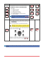
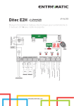
E2H IP1967EN rev. 2012-07-31 EN Installation manual for control panel for 2-motor 24V automations with built-in radio. AUX 24V Power unit ANT JR5 TRF Memory card BATK1 COM ESC POWER ENTER F1 DOWN UP JR1 L N Power supply DITEC S.p.A. Via Mons. Banfi, 3 - 21042 Caronno Pertusella (VA) - ITALY Tel. +39 02 963911 - Fax +39 02 9650314 www.ditec.it - [email protected] + Reversal safety contact Motor1 Output 24 V= Motor2 + Stop safety contact 24V= Output 24 V= 24V= 1 5 9 13 1 5 20 0 1 6 0 1 8 Step by step Partial opening 36 35 34 33 32 31 15 14 0 Step by step Stop Lamp BAT Electric lock Flashing light L N GOL4 INDEX Subject 1. 2. 3. Page General safety precautions EC declaration of conformity Technical data 3.1 Applications 4. 5. Connection of power supply Commands 5.1 SOFA1-SOFA2 or GOPAVRS self-controlled safety edge 6. 7. 8. 9. Outputs and accessories Selection Signals Adjustments 9.1 Switching on and off 9.2 Key combination 9.3 Main menù 6HFRQGOHYHOPHQ$7$XWRPDWLF&RQ¿JXUDWLRQV 6HFRQGOHYHOPHQ%&%DVLF&RQ¿JXUDWLRQV 9.6 Second level menù - BA (Basic Adjustment) 9.7 Second level menù - RO (Radio Operations) 9.8 Second level menù - SF (Special Functions) 9.9 Second level menù - CC (Cycles Counter) 9.10 Second level menù - AP (Advanced Parameters) 10. Display viewing mode 10.1 Automation status display 10.2 Commands and safety devices display 10.3 Alarms and anomalies display 11. 12. 13. 14. Start-up Radio receiver operation Example application of automation with two swinging door wings Example application of automation with one swinging door wings 3 4 4 4 5 6 7 8 9 9 10 10 10 11 12 13 15 19 21 23 24 27 27 27 29 31 32 33 34 CAPTION This symbol indicates instructions or notes regarding safety issues which require particular attention. i This symbol indicates informations which are useful for correct product function. This symbol indicates instructions or notes intended for technical and expert personnel. STOP This symbol indicates operations not to be effected for not compromise the correct operation of the automation. This symbol indicates options and parameters which are only available with the indicated item. This symbol indicates options and parameters which are not available with the indicated item. All right reserved $OOGDWDDQGVSHFL¿FDWLRQVKDYHEHHQGUDZQXSDQGFKHFNHGZLWKWKHJUHDWHVWFDUH7KHPDQXIDFWXUHUFDQQRW KRZHYHUWDNHDQ\UHVSRQVLELOLW\IRUHYHQWXDOHUURUVRPPLVLRQVRULQFRPSOHWHGDWDGXHWRWHFKQLFDORULOOXVWUDWLYH purposes. ,3(1 2 1. GENERAL SAFETY PRECAUTIONS This installation manual is intended for professionally competent personnel only. The installation, the power connections and the settings must be completed in conformity with Good :RUNLQJ0HWKRGVDQGZLWKWKHUHJXODWLRQVLQIRUFH %HIRUHLQVWDOOLQJWKHSURGXFWFDUHIXOO\UHDGWKHLQVWUXFWLRQV%DGLQVWDOODWLRQFRXOGEHKD]DUGRXV7KHSDFNDJLQJ materials (plastic, polystyrene, etc.) should not be discarded in the environment or left within reach of children, as these are a potential source of hazard. %HIRUHEHJLQQLQJWKHLQVWDOODWLRQFKHFNWKDWWKHSURGXFWLVLQSHUIHFWFRQGLWLRQ 'RQRWLQVWDOOWKHSURGXFWLQH[SORVLYHDUHDVDQGDWPRVSKHUHVWKHSUHVHQFHRIÀDPPDEOHJDVRUIXPHVUHpresents a serious threat to safety. 7KHVDIHW\GHYLFHVSKRWRFHOOVVHQVLWLYHHGJHVHPHUJHQF\VWRSHWFPXVWEHLQVWDOOHGWDNLQJLQWRDFFRXQW WKHSURYLVLRQVDQGWKHGLUHFWLYHVLQIRUFH*RRG:RUNLQJ0HWKRGVWKHLQVWDOODWLRQDUHDWKHIXQFWLRQDOORJLFRI the system and the forces developed by the automation. %HIRUHPDNLQJSRZHUFRQQHFWLRQVFKHFNWKDWWKHUDWLQJFRUUHVSRQGVWRWKDWRIWKHPDLQVVXSSO\$PXOtipolar disconnection switch with a contact opening gap of at least 3 mm must be included in the mains VXSSO\&KHFNWKDWXSVWUHDPRIWKHHOHFWULFDOLQVWDOODWLRQDQDGHTXDWHUHVLGXDOFXUUHQWFLUFXLWEUHDNHUDQGDQ RYHUFXUUHQWFXWRXWDUH¿WWHG When requested, connect the automation to an effective earthing system carried out as indicated by current safety regulations. During installation, maintenance and repair operations, cut off the power supply before opening the cover to access the electrical parts. To handle electronic parts, wear earthed antistatic conductive bracelets. The manufacturer of the motorisation declines all responsibility in the event of components which are not compatible with the safe and correct operation of the product. For repairs or replacements of products only original spare parts must be used. 3 ,3(1 2. EC DECLARATION OF CONFORMITY Manufacturer: DITEC S.p.A. $GGUHVVYLD0RQV%DQ¿&DURQQR3OOD9$,7$/< declares that the control panel E2H is in conformity with the provisions of the following EC directives: EMC Directive 2004/108/EC; Low Voltage Directive 2006/95/EC R&TTE Directive 1999/5/EC Caronno Pertusella, 2010-09-09 3. Silvano Siillvvan S a o Angaroni An A ng ga aro ron nii ((Managing Ma M an na ag giing gD Director) ir e ir eccto tor)) TECHNICAL DATA ARCBH OBBI3BH OBBI3BFCH LUXO3BH LUXO4BH FACIL3H FACIL3EH Memory module 3M1OB 3M1AR 3M1LX Power supply F1 fuse Motor output Accessories power supply Temperature Degree of protection Memorizable radio codes Radio frequency 230 V~ F1,6A 24 V 2x4,5 A max 24 V 0,5 A min -20 °C max 55 °C IP55 100 200 [BIXMR2] 433,92 MHz i 3M1FC 50/60 Hz F1,6A 24 V 2x6 A max 24 V 0,5 A min -20 °C max 55 °C IP54 100 200 [BIXMR2] 433,92 MHz NOTE: the given operating and performance features can only be guaranteed with the use of DITEC accessories and safety devices. 3.1 Applications ,3(1 4 4. CONNECTION OF POWER SUPPLY %HIRUHFRQQHFWLQJWKHSRZHUVXSSO\PDNHVXUHWKHSODWHGDWDFRUUHVSRQGWRWKDWRIWKHPDLQVSRZHUVXSSO\ An omnipolar disconnection switch with minimum contact gaps of 3 mm must be included in the mains supply. &KHFNWKDWXSVWUHDPRIWKHHOHFWULFDOLQVWDOODWLRQWKHUHLVDQDGHTXDWHUHVLGXDOFXUUHQWFLUFXLWEUHDNHUDQGD suitable overcurrent cutout. Use a H05RN-F 3G1,5 or H05RR-F 3G1,5 type electric cable and connect to the terminals L (brown), N (blue), (yellow/green) in the automation. Secure the cable using the special cable clamp and remove the outer sheath near the terminal only. Connection to the mains power supply, in the section outside the automation, is made with independent channels and separated from the connections to the control and safety devices. The channels must penetrate a few centimetres inside the automation thorough a hole maximum Ø16 mm. 0DNHVXUHWKHUHDUHQRVKDUSHGJHVWKDWPD\GDPDJHWKHSRZHUVXSSO\FDEOH 0DNHVXUHWKDWWKHPDLQVSRZHUVXSSO\9FRQGXFWRUVDQGWKHDFFHVVRU\SRZHUVXSSO\9FRQGXFtors are separate. 5 ,3(1 5. 1 COMMANDS Command Function 5 N.O. STEP BY STEP OPENING Description Selecting , the closure of the contact activates a closing or opening operation in the sequence: open-stop-close-open. Warning: if automatic closing is enabled, the duration of the stop is selected via the selection . Selecting , the closure of the contact activates an opening operation. 1 6 N.C. SAFETY STOP Selecting , the opening of the safety contact stops and prevents any movement. Note: to set the different contact safety functions, see the parameter settings. 1 6 N.O. CLOSING 1 8 N.C. REVERSAL SAFETY CONTACT 1 9 N.C. STOP Selecting , the closure of the contact activates a closing operation. The opening of the safety contact triggers a reversal of motion (re-opening) during a closing operation. , with the automation idle, Selecting the opening of the contact prevents any operation. Selecting , with the automation idle, the opening of the contact prevents the closing operation only. Opening the safety contact stops the current operation. Note: the Àashing light Àashes. 1 9 N.O. HOLD TO RUN FUNCTION Selecting and , the permanent opening of the safety contact enables the hold to run function. In this state, the opening (1-5) and closing (1-6) controls function only if held in the pressed position, and the automation stops when the controls are released. Any safety devices, plus the automatic closing, are disabled. 20 N.O. PARTIAL OPENING Selecting , the closure of the contact 1 activates a partial opening operation of the door wing FRPPDQGHG E\ PRWRU DQG WKH GXUDWLRQ LV ¿[HG E\ adjustment . Warning: if automatic closing is enabled, the duration of the stop is selected via the adjustment . 1 20 N.C. AUTOMATIC CLOSING Selecting , the permanent closure of the contact enables automatic closing. WARNING: Make a jumper on all NC contacts if not in use. The terminals with the same number are equal ,3(1 6 5.1 SOFA1-SOFA2 or GOPAVRS self-controlled safety edge Command Function SAFETY TEST SOFA1-SOFA2 GOPAVRS 1 0 41 1 6 1 8 Description Insert the electronic card SOFA1-SOFA2 or GOPAVRS in the housing AUX on the control panel. , the terminal 41 activates a safety Selecting edge test before each operation. If the test fails, an alarm message is visualised on the display. N.C. OPENING SAFETY Selecting , connect the output contact of device DEVICE SOFA1-SOFA2 to terminals 1-6 on the control panel (in series with the photocell output contact, if installed). N.C. REVERSAL Selecting , connect the output contact of device SAFETY SOFA1-SOFA2 to terminals 1-8 on the control panel (in series CONTACT with the photocell output contact, if installed). 7 ,3(1 6. OUTPUT AND ACCESSORIES Output Value - Accessories 0 1 24 V / 0,5 A Description Power supply output for external accessories, including automation status lamp. Electronically protected output. - + 1 13 0 14 /3W Automation status lamp (proportional). The light switches off when the automation is closed; the light switches RQ ZKHQ WKH DXWRPDWLRQ LV RSHQ WKH OLJKW ÀDVKHV ZLWK D YDULDEOH frequency while the automation is operating. LAMPH 24 V / 25 W Flashing light (LAMPH). Selecting WKHÀDVKLQJ light activates simultaneously with the opening and closing operation. NOTE: with automatic closing enabled, there is a preÀashing of 3 s that cannot be regulated. Courtesy light. Selecting , it is possible to connect a courtesy light that activates each time a total or partial opening command or closing command is received. The duration of the light can be regulated via the adjustment and . 24 V 0 14 24 V / 25 W max. 0 0 15 15 24 V / 1,2 A 12V~ / 15 W AUX COM BAT ,3(1 Storage module BATK1 2 x 12 V / 2 Ah Electric block 24V. Electric lock 12 V.&RQQHFWWKHVXSSOLHG:UHVLVWDQFHLQ series. 7KHFRQWUROSDQHOLV¿WWHGZLWKDKRXVLQJIRUDSOXJLQFDUGVXFKDV radio receivers, magnetic spirals, etc. The action of the card can be . selected via the selection WARNING: the plug-in cards must be inserted and removed with the power supply disconnected. The storage module allows remote controls to be stored and the type RIFRQWUROSDQHODSSOLFDWLRQWREHGH¿QHGVHH7(&+1,&$/'(7$,/6 on page 4). If the control panel is replaced, the storage module being used can be inserted in the new control panel. WARNING: the storage module must be inserted and removed with the power supply disconnected. Battery operating. 7KHEDWWHULHVDUHNHSWFKDUJHGZKHQWKHSRZHU supply is on. If the power supply is off, the control panel is powered by the batteries until power is re-established or until the battery voltage drops below the safety threshold. If this occurs, the control panel turns off. WARNING: the batteries must always be connected to the control panel for charging. 3eriodically check the ef¿ciency of the batteries. NOTE: the operating temperature of the rechargeable batteries is approximately +5°C/+40°C. 8 7. SELECTION JR1 Description Display mode setting. OFF Visualization mode. It is only possible to visualize the values and parameters present. JR5 Built-in radio receiver. Disabled 8. ON Maintenance mode. It is possible to visualize and modify the values and parameters present. The entry in maintenance mode is indicated by the permanent switching on of the righthand point. Enabled SIGNALS LED POWER ON Flashing Indicates the transfer of data during DMCS programming. 24 V= power supply. 9 ,3(1 9. ADJUSTMENT NOTE: before making all the automation adjustments, insert the dedicated memory module and press , or load the con¿guration applying to the automation installed see options. When the power is connected or in the case of motor non-selection, the display will block all operations and give error message. an i WARNING: the pressure on the keys can be quick less than 2 s or prolonged longer than 2 s. 8nless speci¿ed otherwise, quick pressure is intended. To con¿rm the setting of a parameter, prolonged pressure is necessary. 9.1 Switching on and off The procedure to switch on the display is as follows: SUHVVWKH(17(5NH\ VWDUWRIGLVSOD\IXQFWLRQLQJFKHFN YLVXDOLVDWLRQRI¿UVWOHYHOPHQX The procedure to switch off the display is as follows: SUHVVWKH(6&NH\DQGNHHSLWSUHVVHG NOTE: the display switches off automatically after 60 s of inactivity. 9.2 Key combinations 7KHVLPXOWDQHRXVSUHVVLQJRIWKHNH\VS and ENTER performs an opening command. + = 7KHVLPXOWDQHRXVSUHVVLQJRIWKHNH\VT and ENTER performs a closing command. + = 7KHVLPXOWDQHRXVSUHVVLQJRIWKHNH\VS and T performs a POWER RESET command. (Interruption of the power supply and restart of the automation). + ,3(1 = 10 9.3 Main menu XVHWKHNH\VS and T to select the required function SUHVVWKH(17(5NH\WRFRQ¿UP Display Description $7$XWRPDWLF&RQ¿JXUDWLRQV 7KHPHQXDOORZV\RXWRPDQDJHWKHDXWRPDWLFFRQ¿JXUDWLRQVRIWKHFRQWUROSDQHO %&%DVLF&RQ¿JXUDWLRQV The menu allows to visualise and modify the main settings of the control panel. BA - Basic Adjustments. The menu allows to visualise and modify the main adjustments of the control panel. RO - Radio Operations. The menu allows you to manage the radio operations of the control panel. SF - Special Functions. The menu allows to set the password and manage the special functions in the control panel. CC - Cycles Counter. The menu allows to visualise the number of operations carried out by the automation, and manage the maintenance interventions. AP - Advanced Parameters. The menu allows to visualise and modify the advanced settings and adjustments of the control panel. $IWHUFRQ¿UPLQJWKHVHOHFWLRQ\RXDFFHVVWKHVHFRQGOHYHOPHQX i WARNING: it is possible that, owing to the type of automation and control panel, certain menus are not available. 11 ,3(1 9.4 6HFRQGOHYHOPHQX$7$XWRPDWLF&RQ¿JXUDWLRQV - XVHWKHNH\VS and T to select the required function SUHVVWKH(17(5NH\WRFRQ¿UP The procedures to activate the functions are described in the table. Display Description +3UHGH¿QHGVHWWLQJIRUUHVLGHQWLDOXVH 2s 7KLVVHOHFWLRQORDGVSUHGH¿QHGYDOXHVIRUFHUWDLQVWDQGDUGSDUDPHWHUV AC - enabling of automatic closing : disabled C5 - step-by-step/opening command operation : step-by-step RM - remote control operation : step-by-step : step-by-step AM - AUX coupling board operation SS - selection automation status at start up : open +3UHGH¿QHGVHWWLQJIRUUHVLGHQWLDOXVH 2s 7KLVVHOHFWLRQORDGVSUHGH¿QHGYDOXHVIRUFHUWDLQVWDQGDUGSDUDPHWHUV AC - enabling of automatic closing : enabled TC - setting of automatic closing time : 1 minute C5 - step-by-step/opening command operation : step-by-step RM - remote control operation : step-by-step AM - AUX coupling board operation : step-by-step SS - selection automation status at start up : closed &3UHGH¿QHGVHWWLQJIRUFRQGRPLQLDOXVH 2s 7KLVVHOHFWLRQORDGVSUHGH¿QHGYDOXHVIRUFHUWDLQVWDQGDUGSDUDPHWHUV AC - enabling of automatic closing : enabled TC - setting of automatic closing time : 1 minute C5 - step-by-step/opening command operation : opening RM - remote control operation : opening AM - AUX coupling board operation : opening SS - selection automation status at start up : open RD - Resetting the basic settings (SETTINGS RESET). 2s i WARNING: it is possible that, owing to the type of automation and control panel, certain menus are not available. ,3(1 12 9.5 Second level menu - BC (Basic Configurations) XVHWKHNH\VS and T to select the required function SUHVVWKH(17(5NH\WRFRQ¿UP Display Description 966HOHFWLQJPHFKDQLFDOVWRSVYHUL¿FDWLRQ When enabled (ON), with every power supply connection WKH DXWRPDWLRQ DXWRPDWLFDOO\ FKHFNV WKH PHFKDQLFDO opening and closing end stops and/or the stop limit switches during opening and closing operation at the speed set with the adjustment . During the learning operation, the display visualizes the message . OFF ON 1 2 OFF ON STEP-BY-STEP OPENING STEP-BY-STEP OPENING STEP-BY-STEP OPENING OPEN CLOSED OFF ON OFF ON NW - Selecting number of door wings. AC - Enabling of automatic closing. C5 - Step-by-step/opening command operation. RM - Radio receiver functionality. AM - AUX coupling board operation. SS - Selection of automation status at activation. Indicates how the control panel considers the automation at the time of switch-on, or after a POWER RESET command. (/(QDEOHPHQWRIHOHFWULFORFNUHOHDVHVWURNH :KHQDQHOHFWULFORFNLVSUHVHQWWKHHQDEOHPHQWRIWKHUHOHDVHVWURNHLVUHFRPPHQGHG SO - Enabling reversal safety contact functionality. When enabled (ON) with the automation idle, if the contact 1-8 is open, all operations are prevented. When disabled (OFF) with the automation idle, if the contact 1-8 is open, it is possible to activate the opening operation. 13 ,3(1 Display Description NI - Activation of NIO electronic anti-freeze system. :KHQHQDEOHG21LWPDLQWDLQVWKHHI¿FLHQF\RIWKHPRWRUV even in low temperatures. Note: for correct operation, the control panel must be exposed to the same ambient temperature as the motors. 64 - Functioning of safety stop/closing command. OFF ON STOP CLOSING PARTIAL OPENING AUTOMATIC CLOSING ELECTRIC LOCK ELECTRIC MAGNET COURTESY LIGHT FLASHING LIGHT P2 - Functioning of partial opening command contact 1-20. P3 - Partial opening command. 1-2 - Enablement of automatic closing (2)XQFWLRQLQJRIHOHFWULFORFNHOHFWULFEUDNH 6&)XQFWLRQLQJRIHOHFWULFORFNIXQFWLRQLQJWLPHVHWYLD adjustment ) SF - Functioning of electric magnet powered with automation closed FF - Setting function of 0-14 exit. OF - Courtesy light ON - Flashing light i WARNING: it is possible that, owing to the type of automation and control panel, certain menus are not available. ,3(1 14 9.6 Second level menu - BA (Basic Adjustments) - XVHWKHNH\VS and T to select the required function SUHVVWKH(17(5NH\WRFRQ¿UP i WARNING: the gap between the adjustment values of the parameters may vary according to the type of automation. Display Description MT - Selection of automation type. NO - None O3 - OBBI-ARC F3 - FACIL L3 - LUXO WARNING: it is essential to set the type of automation before PDNLQJWKHDGMXVWPHQWV R1 - Adjustment of motor 1 thrust on obstacles. [%] 7KHFRQWUROSDQHOLV¿WWHGZLWKDVDIHW\GHYLFHZKLFKZKHQ it detects an obstacle: - in opening, stops the movement with a disengagement operation; - in closing, before the deceleration, inverts the movement; - in closing, during the deceleration, stops or inverts the movement according to the type of limit switch installed. R2 - Adjustment of motor 2 thrust on obstacles. [%] 7KHFRQWUROSDQHOLV¿WWHGZLWKDVDIHW\GHYLFHZKLFKZKHQ it detects an obstacle: - in opening, stops the movement with a disengagement operation; - in closing, before the deceleration, inverts the movement; - in closing, during the deceleration, stops or inverts the movement according to the type of limit switch installed. RP - Adjustment of the partial opening measurement. [%] Adjusts the percentage of operation in relation to the total opening of the automation. FA - Selection of opening limit switch mode. NO - None RA - Deceleration limit switch (after the activation, the door wing slows down its movement) SX - Stop limit switch (after the activation, the door wing stops its movement) PX - Proximity limit switch (after the activation, the door wing continues as far as the end stop) 15 NONE OBBI-ARC FACIL LUXO 0% 99% 0% 99% 10% 99% NONE DECELERATION STOP PROXIMITY ,3(1 Display Description FC - Selection of closing limit switch mode. NO - None RA - Deceleration limit switch (after the activation, the door wing slows down its movement) SX - Stop limit switch (after the activation, the door wing stops its movement) PX - Proximity limit switc (after the activation, the door wing continues as far as the end stop) VA - Setting opening speed. [V] NONE DECELERATION STOP PROXIMITY MIN MAX MIN MAX MIN MAX 0 SECONDS 59 SECONDS 1 MINUTE 2 MINUTE MIN MAX MIN MAX VC - Setting closing speed. [V] VR - Setting acquisition manoeuvre speed. [V] i WARNING: the acquisition manoeuvre speed can only be adjusted with the setting . TC - Setting automatic closing time. [s] Adjustment occurs with intervals of varying sensitivity. - from 0 to 59 sec with 1 sec intervals; - from 1 to 2 min with 10 sec intervals. M1 - Setting motor 1 manoeuvre time. [s] Adjustment, in seconds, of the total manoeuvre time for motor 1. i WARNING: adjustment occurs with a sensitivity interval of 0.5 sec, indicated by the switching on of the right-hand point. Example: = 7 seconds = 7,5 seconds M2 - Setting motor 2 manoeuvre time. [s] Adjustment, in seconds, of the total manoeuvre time for motor 2. i WARNING: adjustment occurs with a sensitivity interval of 0.5 sec, indicated by the switching on of the right-hand point. Example: = 7 seconds = 7,5 seconds ,3(1 16 Display Description TR - Setting motor 1 closing delay time. [s] Adjustment, in seconds, of the delay time for starting the manoeuvre of motor 1, in relation to motor 2. MIN MAX MIN MAX TO - Impostazione tempo di ritardo motore 2 in apertura. [s] Regolazione in secondi del tempo di ritardo della partenza di manovra del motore 2 rispetto al motore 1. LU - Setting switch-on time for courtesy light. [s] Adjustment occurs with intervals of varying sensitivity. - from 0 to 59 sec with 1 sec intervals; - from 1 to 2 min with 10 sec intervals; - from 2 to 3 min with 1 min intervals; NO - Disabled ON - Permanent switch-on, switch-off using radio command i WARNING: the courtesy light switches on at the start of each operation. LG - Setting switch-on time for independent light. [s] Adjustment occurs with intervals of varying sensitivity. - from 0 to 59 sec with 1 sec intervals; - from 1 to 2 min with 10 sec intervals; - from 2 to 3 min with 1 min intervals; NO - Disabled ON - Switch-on and switch-off using radio command i WARNING: the switching on of the light does not depend on the start of an operation, but it is possible to FRQWUROLWVHSDUDWHO\XVLQJWKHUHOHYDQWWUDQVPLWWHUNH\ DISABLED 1 SECOND 59 SECONDS 1 MINUTE 2 MINUTES 3 MINUTES ON DISABLED 1 SECOND 59 SECONDS 1 MINUTE 2 MINUTES 3 MINUTES ON MIN MAX /56HWWLQJHOHFWULFORFNUHOHDVHWLPH>V@ ON - Active throughout the entire operation ON TS - Setting renewal of automatic closing time after safety release. [%] MIN 17 MAX ,3(1 Display i Description :26HWWLQJRSHQLQJSUHÀDVKLQJWLPH>V@ Adjustment, in seconds, of the lead time for the switch-on RIWKHÀDVKLQJOLJKWLQUHODWLRQWRWKHVWDUWRIWKHPDQRHXYUH from a voluntary command. :&6HWWLQJFORVLQJSUHÀDVKLQJWLPH>V@ Adjustment, in seconds, of the lead time for the switch-on RIWKHÀDVKLQJOLJKWLQUHODWLRQWRWKHVWDUWRIWKHPDQRHXYUH from a voluntary command. MIN MAX MIN MAX WARNING: it is possible that, owing to the type of automation and control panel, certain menus are not available. ,3(1 18 9.7 Second level menu - RO (Radio Operations) XVHWKHNH\VS and T to select the required function SUHVVWKH(17(5NH\WRFRQ¿UP The procedures to activate the functions are described in the table. Display Description SR - Transmitter memory storage. ...x2, x3... It is possible to directly access the Transmitter memory storage menu with the display switched off, but only with Display visualization mode set at 00 or 03: - by transmitting a remote control not present in the memory, - by transmitting an unstored channel of a remote control already present in the memory. ER - Deleting a single transmitter. 2s EA - Total memory deleting. 2s 2s EC - Deleting a single code. (FUTURE USE) RE - Setting memory opening from remote control. When enabled (ON) remote programming is activated. To memorise new transmitters without using the control panel, SUHVVDQGKROGGRZQWKH35*NH\RIDQDOUHDG\PHPRULVHG GOL4 transmitter for 5 seconds until the LED switches on ZLWKLQWKHFDSDFLW\RIWKHUHFHLYHUDQGSUHVVDQ\&+NH\RI the new transmitter. NOTE: make sure that undesired transmitters are not accidently memorized. MU - Setting the maximum number of transmitters that can be memorized on a memory module. It is possible to memorise up to 100 or 200 rolling code transmitters. NOTE: it is necessary to set to allow the system con¿guration to be saved on the memory module 19 OFF ON 200 100 ,3(1 Display Description &6HWWLQJNH\IXQFWLRQRIPHPRUL]HGWUDQVPLWWHU &6HWWLQJNH\IXQFWLRQRIPHPRUL]HGWUDQVPLWWHU &6HWWLQJNH\IXQFWLRQRIPHPRUL]HGWUDQVPLWWHU &6HWWLQJNH\IXQFWLRQRIPHPRUL]HGWUDQVPLWWHU NO - None 1-3 - Opening command 1-4 - Closing command 1-5 - Step-by-step command P3 - Partial opening command LG - Courtesy light status change command 1-9 - STOP command i WARNING: 1-3 (opening) and 1-5 (step-by-step) are binary options and are dependent by the selection. NONE OPENING CLOSING STEP-BY-STEP PARTIAL COURTESY LIGHT STOP 5.1DYLJDWLRQYLDWUDQVPLWWHUNH\ERDUG :LWKWKHGLVSOD\VZLWFKHGRIITXLFNO\W\SHWKHVHTXHQFHRI NH\V 3 3 2 4 1 using the desired memorized transmitter. Note: it is recommended to use a dedicated transmitter. WARNING: during navigation via transmitter keyboard, NONE of the memorized transmitters are active. 7RWHVWWKHQHZFRQ¿JXUDWLRQVZLWFKRIIWKHGLVSOD\DQGJLYH DQRSHQFRPPDQGXVLQJNH\ 3 . OFF 1 3 ON 2 4 1DYLJDWLRQ YLD WUDQVPLWWHU NH\ERDUG LV DXWRPDWLFDOO\ GLVD. bled after 4 minutes of inactivity or by setting i Warning: it is possible that, owing to the type of automation and control panel, certain menus are not available. ,3(1 20 9.8 Second level menu - SF (Special Functions) XVHWKHNH\VS and T to select the required function SUHVVWKH(17(5NH\WRFRQ¿UP The procedures to activate the functions are described in the table. Display Description SP - Setting the password (EXAMPLE) i 2s Note: this is only possible when the password is not set. The setting of the password prevents unauthorised personnel from accessing selections and adjustments. It is possible to annul the set password by selecting the sequence JR1=ON, JR1=OFF, JR1=ON. IP - Inserting the password. (EXAMPLE) i 2s Note: this is only possible when the password is set. When the password is not inserted, it is possible to access the visualisation mode regardless of the selection made with JR1. When the password is inserted, it is possible to access the maintenance mode. RD - Resetting the basic settings (SETTINGS RESET). 2s (8'HOHWLQJRIWKHXVHUFRQ¿JXUDWLRQVDQGWKHODVWFRQ¿JXUDWLRQVHWSUHVHQWLQWKH memory module. 2s 696DYLQJXVHUFRQ¿JXUDWLRQ (EXAMPLE) Selecting the memory positions panel. 2s LWLVSRVVLEOHWRVDYHXSWRSHUVRQDOLVHGFRQ¿JXUDWLRQVLQ and only with the storage module present on the control 21 ,3(1 Display Description 5&/RDGLQJFRQ¿JXUDWLRQ (EXAMPLE) 2s ,WLVSRVVLEOHWRORDGWKHFRQ¿JXUDWLRQVSUHYLRXVO\VDYHGRUORDGWKHSUHGH¿QHGVHWWLQJV , , and 7KHSUHGH¿QHGVHWWLQJVDUH available in the memory positions as follows: : OBBI : FACIL : LUXO : ARC /RDGLQJDSUHGH¿QHGVHWWLQJVWDQGDUGDYHUDJHYDOXHVDUHDXWRPDWLFDOO\VHWIRUFHUWDLQ parameters (type of automation, operation speed, operation times and deceleration times). 5//RDGLQJWKHODVWFRQ¿JXUDWLRQVHW NOTE: the control panel automatically saves the last con¿guration set, and keeps it memorised in the storage module. In the event of a fault or the replacement of the control panel, it is possible to restore the last con¿guration of the automation by inserting the storage module and loading the last con¿guration set. 2s &89LHZLQJWKHHOHFWURQLFSDQHO¶V¿UPZDUHYHUVLRQ = Release 0.3.4 (example) i i Note: view only. WARNING: it is possible that, owing to the type of automation and control panel, certain menus are not available. ,3(1 22 9.9 Second level menu - CC (Cycles Counter) XVHWKHNH\VS and T to select the required function SUHVVWKH(17(5NH\WRFRQ¿UP The procedures to activate the functions are described in the table. Display Description CV - View total manoeuvres counter. = 241.625 manoeuvres (example) i Note: view only. CA - Setting the maintenance alarm interval. (max 500.000 partial manoeuvres) (EXAMPLE) (EXAMPLE) = 08 08 50 00 = 85.000 manoeuvres (ex) = 50 = 00 2s It is possible to set the required number of operations for the signalling of the maintenance alarm. OA - Selecting maintenance alarm viewing mode. 00 - Display (display alarm message ) 01 - Flashing light DISPLAY FLASHING ZKHQDXWRPDWLRQLVFORVHGLWÀDVKHVWLPHVHYHU\ minutes) 02 - Open gate indicator light ZKHQDXWRPDWLRQLVFORVHGLWÀDVKHVWLPHVHYHU\ INDICATOR minutes) CP - View partial manoeuvres counter. = 71.625manoeuvres (example) i Note: view only. ZP - Resetting partial manoeuvres counter. 2s To ensure correct operation, it is recommended to reset the partial manoeuvres counter: - after each maintenance intervention, - after each setting of the maintenance alarm interval. i Warning: it is possible that, owing to the type of automation and control panel, certain menus are not available. 23 ,3(1 9.10 Second level menu - AP (Advanced Parameters) XVHWKHNH\VS and T to select the required function SUHVVWKH(17(5NH\WRFRQ¿UP i WARNING: the gap between the adjustment values of the parameters may vary according to the type of automation. Given the complexity of the parameters, use of the Advanced Parameters menu is recommended only IRUTXDOL¿HGWHFKQLFDOSHUVRQQHO Display Description AA - Activating advanced parameters menu. i NOTE: activation necessary before being able to scroll through the AP menu. OFF ON OFF ON MIN MAX MIN MAX OFF ON ET - Enabling of safety test (SOFA1-A2 card). DO - Setting of disengagement on obstacle during opening. [s] DC - Setting of disengagement on obstacle during closing. [s] PP - Step-by-step sequence with commands 1-5. OFF - Opening-Stop-Closing-Opening ON - Opening-Stop-Closing-Stop-Opening S5 - Duration of STOP in step-by-step sequence with commands 1-5. TEMPORARY PERMANENT R9 - Enablement of automatic closing after command 1-9 (STOP). When enabled (ON), after a command 1-9 the automation carries out the automatic closing (if enabled), after the set time. TA - Adjustment acceleration phase. [%] ,3(1 24 OFF ON FAST SLOW Display Description TP - Setting of automatic closing time after partial opening. [s] Adjustment occurs with intervals of varying sensitivity. - from 0 to 59 sec with 1 sec intervals; - from 1 to 2 min with 10 sec intervals. 0 SECONDS 59 SECONDS 1 MINUTE 2 MINUTES MIN MAX MIN MAX MIN MAX MIN MAX NONE RADIO TEST STATUS COMMANDS NONE EDGE PO - Approaching/deceleration speed during opening. [V] PC - Approaching/deceleration speed during closing. [V] 2%'HFHOHUDWLRQEUDNLQJWLPHGXULQJRSHQLQJ>V@ &%'HFHOHUDWLRQEUDNLQJWLPHGXULQJFORVLQJ>V@ DS - Setting of display viewing mode. 00 - No display 01 - Commands and safety devices with radio test (see paragraph 10.2) 02 - Automation status (see paragraph 10.1) 03 - Commands and safety devices (see paragraph 10.2) NOTE: setting 01 allows to view the reception of a radio transmission for checking its range. D6 - Selecting device connected to terminals 1-6. NO - None SE - Safety edge PH - Photocells PHOTOCELLS D8 - Selecting device connected to terminals 1-8. NO - None SE - Safety edge PH - Photocells NONE EDGE PHOTOCELLS 25 ,3(1 Display Description SM - Selection of the operating mode of photocell terminals 1-6. (only with ). 00 - During manoeuvre, the opening of the safety contact stops movement with disengagement. 01 - During manoeuvre, the opening of the safety contact STOP + stops movement with disengagement. When the contact DISENGAGE is reclosed the interrupted manoeuvre resumes. 02 - During manoeuvre, the opening of the safety contact stops movement with disengagement. When the contact is reclosed an opening manoeuvre starts. STOP + 03 - During a closing manoeuvre, the opening of the safety OPENING contact reverses the movement. TN - Setting intervention temperature for NIO anti-freeze system. [°C] $GMXVWPHQWRIWKHZRUNLQJWHPSHUDWXUHRIWKHFRQWUROSDQHO DOES NOT refer to outside temperature. -6 ºC STOP + RESUME REVERSE CLOSING +6 ºC TB - View control panel temperature. DO NOT USE OL - Selecting open gate indicator light mode. When set ON, the light is switched off when automation is closed; it is switched on when automation is open and during the opening and closing phases. When set OFF the light is switched off when automation is FORVHGLWLVVZLWFKHGRQZKHQDXWRPDWLRQLVRSHQLWÀDVKHV during the opening and closing phases. i OFF ON FLASHING ON WARNING: it is possible that, owing to the type of automation and control panel, certain menus are not available. ,3(1 26 10. DISPLAY VIEWING MODE i WARNING: it is possible that, owing to the type of automation and control panel, certain menus are not available. 10.1 Automation status display i Warning: the automation status display mode is visible only with the Display viewing mode set on 02. Display Description Automation closed. Automation open. Automation stopped in intermediate position. Automation closing. Automation opening. Automation closing from partial opening. Automation in partial opening. Automation partially open. 10.2 Commands and safety devices display i WARNING: the commands and safety device display mode is only visible with the Display viewing mode set on 01 or 03. Display Description 1-2 - Automatic closing activation command. 1-3 - Opening command. 1-4 - Closing command. 1-5 - Step-by-step command. 27 ,3(1 1-6 - Safety with opening and closing stop. 1-8 - Safety with closing reversal. 1-9 - STOP command. P3 - Partial opening command. 3P - Hold-to-run opening command. 4P - Hold-to-run closing command. 5;5DGLRUHFHSWLRQRIDQ\PHPRULVHGWUDQVPLWWHUNH\SUHVHQWLQWKHPHPRU\PRGXOH 1;5DGLRUHFHSWLRQRIDQ\NH\QRWPHPRULVHG CX - AUX coupling board command reception. F1 - Generic limit switch relating to motor 1. F2 - Generic limit switch relating to motor 2. O1 - Detection of an obstacle by motor 1 or arrival of motor 1 at mechanical stop. O2 - Detection of an obstacle by motor 2 or arrival of motor 2 at mechanical stop. RV - Enablement/disablement of built-in radio receiver via JR5. MQ - Acquisition of mechanical stops in progress. HT - Heating of the motors (NIO function) in progress. J1 - Variation of the JR1 jumper status. 1C - Closing manoeuvre 1 wing at a time. ,3(1 28 10.3 Alarms and anomalies display i WARNING: alarms and anomalies are displayed when any display selection is made. The signaling of DODUPPHVVDJHVWDNHVSULRULW\RYHUDOORWKHUGLVSOD\V Type of alarm Display Description Remedy M0 - Automation type not selected. If the dedicated memory module is present press . Select a type of automation. MB - Absence of motor 1 during an ope- &KHFNWKHFRQQHFWLRQRIPRWRU ration. Mechanical alarm MC - Absence of motor 2 during an opera- &KHFNWKHFRQQHFWLRQRIPRWRU tion (if 2-motor functioning has been set). MD - Irregular functioning of motor 1 ope- &KHFNWKHFRQQHFWLRQRIWKHPRWRURSHning limit switch. ning limit switch. ME - Irregular functioning of motor 1 clo- &KHFNWKHFRQQHFWLRQRIWKHPRWRUFORsing limit switch. sing limit switch. MF - Irregular functioning of motor 2 ope- &KHFNWKHFRQQHFWLRQRIWKHPRWRURSHning limit switch. ning limit switch. MG - Irregular functioning of motor 2 clo- &KHFNWKHFRQQHFWLRQRIWKHPRWRUFORsing limit switch. sing limit switch. 9HULI\WKDWWKHPRWRUZKLFKRSHQV¿UVW0 LVFRQQHFWHGDVVKRZQLQ¿J MH - Incorrect wings overlap. Radio operations alarm MI - Detection of third consecutive obsta- &KHFNIRUWKHSUHVHQFHRISHUPDQHQWREcle. stacles along the automation path. R0 - Insertion of a memory module containing more than 100 memorized transmitters. Warning: the setting is automatic. 7R VDYH WKH VHW FRQ¿JXUDWLRQV LQ WKH PHmory module, cancel a few memorized transmitters to bring the total lower than 100. Set . R3 - Memory module not detected. Insert a memory module. R4 - Memory module not compatible with Insert a compatible memory module. control panel. 29 ,3(1 Display Service Accessories alarm Type of alarm ,3(1 Description Remedy A0 - Failure of test of safety sensor on con- &KHFN WKH GHYLFH 62)$$ LV ZRUNLQJ tact 6. correctly. If the supplementary SOF card is not inVHUWHGFKHFNWKHVDIHW\WHVWLVGLVDEOHG A3 - Failure of test of safety sensor on con- &KHFN WKH GHYLFH 62)$$ LV ZRUNLQJ tact 8. correctly. If the supplementary SOF card is not inVHUWHGFKHFNWKHVDIHW\WHVWLVGLVDEOHG A7 - Incorrect connection of contact 9 to Connect the 1-9 contact terminal 41. V0 - Request for maintenance interven- Proceed with the scheduled maintenance tion. intervention. 30 11. STARTING WARNING: the system must have mechanical doorstops of appropriate strength or limit switches must be installed. WARNING: if this control panel is being used to replace a faulty one, it is possible to reset the last automation con¿guration by inserting the storage module of the old control panel in the housing on the new one, then loading the last con¿guration set with the command. 0DNHDMXPSHUIRUVDIHW\FRQWDFWV6HW-5 21-5 21 11.2 If limit switches are used, adjust them by manually moving the wings as described here: - deceleration limit switch: activation of the limit switch must occur before the mechanical doorstop, - stop limit switch: activation of the stop limit switch must occur in the open/close position of the wings, - proximity limit switch: activation of the proximity limit switch must occur near the mechanical doorstop. 11.3 Switch on power. Warning: the following operations are performed with no safety devices. 11.4 If the dedicated memory module is present, press , if it is not present, load the FRQ¿JXration related to the type of automation installed. 11.5 If the automation has 1 door wing, set . 11.6 Verify the setting. + DQGFKHFNWKH 11.7 With the automation idle in the intermediate position, give a closing command door wings move in the correct direction. In the event of an incorrect connection, invert the polarity of the motor. Note: the ¿rst closing operation after a power supply interruption is carried out with one door wing at a time, at reduced speed. 11.8 Give an opening command + and verify that the automation carries out the operation at reduced speed stopping at the mechanical doorstops during the opening phase. menu. /RDGWKHSUHGH¿QHGVHWWLQJPRVWVXLWDEOHIRUV\VWHPDYDLODEOHLQWKH ,IOLPLWVZLWFKHVDUHXVHGGH¿QHWKHLUXVHE\PHDQVRIVHWWLQJV and . ,QRUGHUWRVDYHWKHFRQ¿JXUDWLRQVLQWKHPHPRU\PRGXOHLWLVQHFHVVDU\WRVHW . 11.12 To modify the operation and deceleration speed settings, the automatic closing times, and the thrust on obstacles, consult the menus. 11.13 Connect the safety devices (removing all relevant jumpers) and verify their correct operation. Note: ensure that the forces exerted by the door wings are compliant with EN12453-EN12445 regulations. 11.14 If desired, memorize the radio commands with command (refer to chapter 12). &RQQHFWDQ\RWKHUDFFHVVRULHVDQGFKHFNRSHUDWLRQ 2QFHWKHVWDUWXSDQGFKHFNSURFHGXUHVDUHFRPSOHWHGFORVHWKHFRQWDLQHU 31 ,3(1 12. RADIO RECEIVER OPERATION Ricevitore / Receiver CH1 CH2 CH3 CH4 PRG 1 2 10 s 3 The control panel is equipped with a radio receiver with a frequency of 433.92 MHz. The antenna consists of a rigid wire, 173 mm long, connected to the ANT clamp. ,WLVSRVVLEOHWRLQFUHDVHWKHUDQJHRIWKHUDGLRE\FRQQHFWLQJWKHDQWHQQDRIWKHÀDVKLQJOLJKWVRUE\LQVWDOOLQJ the tuned BIXAL antenna. NOTE: to connect the external antenna to the control panel, use a coaxial cable type RG58 max 10 m. &KHFNWKDWWKHVWRUDJHPRGXOHLVLQVHUWHGRQ&20FRQQHFWRURIWKHFRQWUROSDQHO Up to 100 remote controls can be stored in the storage module. WARNING: if the radio receiver on the control panel is not used, set JR5=OFF and remove the storage module. Transmitter storage: press the PRG button on the radio receiver or on the control panel; the SIG LED lights up; PDNHDWUDQVPLVVLRQE\SUHVVLQJRQHRIWKHGHVLUHG&+EXWWRQVRIWKHWUDQVPLWWHUZLWKLQWKHUDQJHRIWKH UDGLRUHFHLYHU7KHWUDQVPLWWHULVQRZVWRUHG'XULQJWKLVSKDVHWKH6,*/('ÀDVKHV:KHQWKH6,*/(' LVDJDLQOLWXSLWLVSRVVLEOHWRYDOLGDWHDQRWKHUWUDQVPLWWHU9DOLGDWHDOOWKHQHZWUDQVPLWWHUVE\PDNLQJD transmission as indicated; you automatically exit the procedure 10 seconds after the last transmission, or you can press the PRG button again (the SIG LED goes off). 8SWRIRXU&+NH\VRIDVLQJOHUHPRWHFRQWUROFDQEHVWRUHG LIRQO\RQHDQ\&+NH\RIWKHUHPRWHFRQWUROLVVWRUHGFRPPDQGVWHSE\VWHSRSHQLQJLVFDUULHG out; IURPWZRWRIRXU&+NH\VRIDVLQJOHUHPRWHFRQWURODUHVWRUHGWKHIXQFWLRQVPDWFKHGZLWKWKH&+NH\V are as follows: &+ FRPPDQGVWHSE\VWHSRSHQLQJ &+ SDUWLDORSHQLQJFRPPDQGLWFDXVHVWKHDXWRPDWLRQWRRSHQIRUDERXWP &+ FRPPDQGWRVZLWFKRQRIIWKHFRXUWHV\OLJKW &+ VWRSFRPPDQGHTXLYDOHQWWRLPSXOVLYHFRPPDQG Transmitter cancellation: NHHSSUHVVHGIRUVWKH35*EXWWRQRQWKHUDGLRUHFHLYHURURQWKHFRQWUROSDQHOWKH6,*/('EHJLQVWR ÀDVK WRHUDVHDOOWKHWUDQVPLWWHUVIURPWKHPHPRU\RIWKHUDGLRUHFHLYHUNHHSSUHVVHGIRUVDJDLQWKH35* button; WRHUDVHDVLQJOHWUDQVPLWWHUSUHVVRQHRIWKHSUHYLRXVO\VWRUHG&+NH\VRIWKHWUDQVPLWWHUWREHHUDVHG WKHFDQFHOODWLRQLVFRQ¿UPHGE\WKHTXLFNÀDVKLQJRIWKH6,*/(' For further information see the user manual for GOL series transmitters. If the control panel is replaced, the storage module being used can be inserted in the new control panel. WARNING: the storage module must be inserted and removed with the power supply disconnected. ,3(1 32 13. EXAMPLE APPLICATION OF AUTOMATION WITH TWO SWINGING DOOR WINGS When the E2H control panel is used in applications for double wings automations with overlapSLQJLWLVSRVVLEOHWRPDNHWKHIROlowing connections. 36 35 34 33 32 31 24V= 24V= Motor 2 Motor 1 (Fig. 13.1) Installation with mechanical doorstops in opening and closing phases, without the use of electric limit switches. 2 1 (Fig. 13.2) Installation with mechanical doorstop in closing phases, with the use of electric limit switches. Fig. 13.1 36 35 34 33 32 31 24V= 24V= Motor 2 Motor 1 2 1 Fig.13.2 33 ,3(1 14. EXAMPLE APPLICATIONS FOR AUTOMATION WITH ONE SWINGING DOOR WING When the E2H control panel is used in applications for single wing DXWRPDWLRQVLWLVSRVVLEOHWRPDNH the following connections. 33 32 31 24V= Motor 1 (Fig. 14.1) Installation with mechanical doorstops in opening and closing phases, without the use of electric limit switches. 1 (Fig. 14.2) Installation with mechanical doorstop in closing phases, with the use of electric limit switches. Fig. 14.1 33 32 31 24V= Motor 1 1 Fig. 14.2 ,3(1 34 35 ,3(1 TM DITEC S.p.A. 9LD0RQV%DQ¿&DURQQR3OOD9$,WDO\7HO)D[ www.ditec.it [email protected] DITEC BELGIUM LOKEREN Tel. +32 9 3560051 Fax +32 9 3560052 www.ditecbelgium.be DITEC DEUTSCHLAND OBERURSEL Tel. +49 6171 914150 Fax +49 6171 9141555 www.ditec-germany.de DITEC ESPAÑA ARENYS DE MAR Tel. +34 937958399 Fax +34 937959026 www.ditecespana.com DITEC FRANCE MASSY Tel. +33 1 64532860 Fax +33 1 64532861 www.ditecfrance.com DITEC GOLD PORTA ERMESINDE-PORTUGAL Tel. +351 22 9773520 Fax +351 22 9773528/38 www.goldporta.com DITEC SWITZERLAND BALERNA Tel. +41 848 558855 Fax +41 91 6466127 www.ditecswiss.ch DITEC ENTREMATIC NORDIC LANDSKRONA-SWEDEN Tel. +46 418 514 50 Fax +46 418 511 63 www.ditecentrematicnordic.com DITEC TURCHIA ISTANBUL Tel. +90 21 28757850 Fax +90 21 28757798 www.ditec.com.tr DITEC AMERICA ORLANDO-FLORIDA-USA Tel. +1 407 8880699 Fax +1 407 8882237 www.ditecamerica.com DITEC CHINA SHANGHAI Tel. +86 21 62363861/2 Fax +86 21 62363863 www.ditec.cn