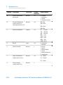
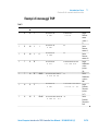
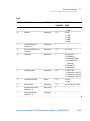
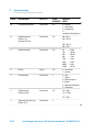
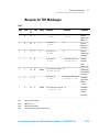
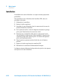
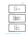
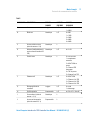
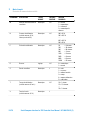
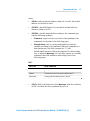
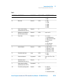
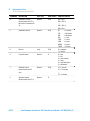
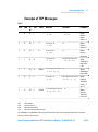
1
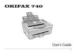
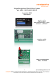
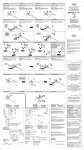
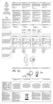
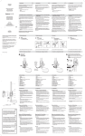
Serial Computer Interface for TSP Controller Models 929-0024, 929-0025, 929-0026 Manuale di Istruzioni Bedienungshandbuch Notice de Mode D’Emploi User Manual 87-900-079-01 (F) 05/2011 Warranty Notices © Agilent Technologies, Inc. 2011 No part of this manual may be reproduced in any form or by any means (including electronic storage and retrieval or translation into a foreign language) without prior agreement and written consent from Agilent Technologies, Inc. as governed by United States and international copyright laws. Manual Part Number Publication Number: 87-900-079-01 (F) Edition Edition 05/2011 Printed in ITALY Agilent Technologies Italia S.p.A. Vacuum Products Division Via F.lli Varian, 54 10040 Leinì (TO) ITALY The material contained in this document is provided “as is,” and is subject to being changed, without notice, in future editions. Further, to the maximum extent permitted by applicable law, Agilent disclaims all warranties, either express or implied, with regard to this manual and any information contained herein, including but not limited to the implied warranties of merchantability and fitness for a particular purpose. Agilent shall not be liable for errors or for incidental or consequential damages in connection with the furnishing, use, or performance of this document or of any information contained herein. Should Agilent and the user have a separate written agreement with warranty terms covering the material in this document that conflict with these terms, the warranty terms in the separate agreement shall control. Technology Licenses The hardware and/or software described in this document are furnished under a license and may be used or copied only in accordance with the terms of such license. Restricted Rights Legend If software is for use in the performance of a U.S. Government prime contract or subcontract, Software is delivered and licensed as “Commercial computer software” as defined in DFAR 252.227-7014 (June 1995), or as a “commercial item” as defined in FAR 2.101(a) or as “Restricted computer software” as defined in FAR 52.227-19 (June 1987) or any equivalent agency regulation or contract clause. Use, duplication or disclosure of Software is subject to Agilent Technologies’ standard commercial license terms, and nonDOD Departments and Agencies of the U.S. Government will receive no greater than Restricted Rights as defined in FAR 52.227-19(c)(1-2) (June 1987). U.S. Government users will receive no greater than Limited Rights as defined in FAR 52.227-14 (June 1987) or DFAR 252.227-7015 (b)(2) (November 1995), as applicable in any technical data. Trademarks Windows and MS Windows are U.S. registered trademarks of Microsoft Corporation. Safety Notices CAUTION A CAUTION notice denotes a hazard. It calls attention to an operating procedure, practice, or the like that, if not correctly performed or adhered to, could result in damage to the product or loss of important data. Do not proceed beyond a CAUTION notice until the indicated conditions are fully understood and met. WARNING A WARNING notice denotes a hazard. It calls attention to an operating procedure, practice, or the like that, if not correctly performed or adhered to, could result in personal injury or death. Do not proceed beyond a WARNING notice until the indicated conditions are fully understood and met. Serial Computer Interface for TSP Controller User Manual / 87-900-079-01 (F) Serial Computer Interface for TSP Controller Serial Computer Interface for TSP Controller Serial Computer Interface for TSP Controller User Manual / 87-900-079-01 (F) 3/76 Serial Computer Interface for TSP Controller 4/76 Serial Computer Interface for TSP Controller User Manual / 87-900-079-01 (F) Contents Contents 1 Istruzioni per l’uso 7 Informazioni Generali 8 Descrizione delle schede di interfaccia seriale per il controller TSP 9 Dimensioni delle schede di interfaccia 11 Immagazzinamento 12 Smaltimento 12 Preparazione per l’installazione 13 Installazione 14 Protocollo di comunicazione seriale 16 2 Gebrauchsanleitung 23 Allgemeines 24 Beschreibung der Karten zum seriellen Anschluss von TSPControllern 25 Abmessungen der Seriellen Karten Lagerung 27 28 Entsorgung 28 Vor Installation 29 Installation 30 Serielles Datenübertragungs-Protokoll 32 Serial Computer Interface for TSP Controller User Manual / 87-900-079-01 (F) 5/76 Contents 3 Mode d’emploi 39 Indications Generales 40 Description des cartes d'interface serielles pour le controleur TSP 41 Dimensions des cartes d'interface 43 Emmagasinage 44 Mise au rebut 44 Preparation pour l'installation 45 Installation 46 Protocole de communication serielle 48 4 Instructions for Use 55 General Information 56 TSP Controller Serial Interface PCB Description 57 Interface Boards Dimensions 59 Storage 60 Disposal 60 Preparation for Installation 61 Installation 62 Serial Communication Protocol 64 6/76 Serial Computer Interface for TSP Controller User Manual / 87-900-079-01 (F) Serial Computer Interface for TSP Controller User Manual 1 Istruzioni per l’uso Informazioni Generali 8 Descrizione delle schede di interfaccia seriale per il controller TSP 9 Dimensioni delle schede di interfaccia 11 Immagazzinamento 12 Smaltimento 12 Preparazione per l’installazione 13 Installazione 14 Protocollo di comunicazione seriale 16 Formato di comunicazione 16 Protocollo di comunicazione 16 Esempi di messaggi TSP 21 Traduzione delle istruzioni originali 7/76 Istruzioni per l’uso Informazioni Generali 1 Informazioni Generali Questa apparecchiatura è destinata ad uso professionale. L'utilizzatore deve leggere attentamente il presente manuale di istruzioni ed ogni altra informazione addizionale fornita dalla Agilent prima dell'utilizzo dell'apparecchiatura. La Agilent si ritiene sollevata da eventuali responsabilità dovute all'inosservanza totale o parziale delle istruzioni, ad uso improprio da parte di personale non addestrato, ad interventi non autorizzati o ad uso contrario alle normative nazionali specifiche. Nei paragrafi seguenti sono riportate tutte le informazioni necessarie a garantire la sicurezza dell'operatore durante l'utilizzo dell'apparecchiatura. Questo manuale utilizza le seguenti convenzioni: AVVERTENZA! I messaggi di avvertenza attirano l’attenzione dell’operatore su una procedura o una pratica specifica che, se non eseguita in modo corretto, potrebbe provocare gravi lesioni personali. ATTENZIONE! I messaggi di attenzione sono visualizzati prima di procedure che, se non osservate, potrebbero causare danni all’apparecchiatura. NOTA 8/76 Le note contengono informazioni importanti estrapolate dal testo. Serial Computer Interface for TSP Controller User Manual / 87-900-079-01 (F) Istruzioni per l’uso Descrizione delle schede di interfaccia seriale per il controller TSP 1 Descrizione delle schede di interfaccia seriale per il controller TSP Sono disponibili tre modelli di schede di interfaccia seriale per il controller TSP corrispondenti ad altrettanti tipi di protocollo di comunicazione (vedere le figure seguenti): modello 929-0024: Scheda seriale RS 232 modello 929-0025: Scheda seriale RS 422 modello 929-0026: Scheda seriale RS 485. Figura 1 Scheda seriale RS 232 modello 929-0024 Serial Computer Interface for TSP Controller User Manual / 87-900-079-01 (F) 9/76 1 Istruzioni per l’uso Descrizione delle schede di interfaccia seriale per il controller TSP Figura 2 Scheda seriale RS 422 modello 929-0025 Figura 3 Scheda seriale RS 485 modello 929-0026 10/76 Serial Computer Interface for TSP Controller User Manual / 87-900-079-01 (F) Istruzioni per l’uso Dimensioni delle schede di interfaccia 1 Tutti i modelli delle schede sono costituiti da un circuito elettronico che provvede a decodificare i comandi ricevuti dal computer remoto negli opportuni segnali di controllo per il TSP Controller, ed a codificare ed inviare i dati rilevati dal TSP Controller al computer remoto. Il kit fornito per tutti i modelli è costituito dai seguenti elementi: la scheda di interfaccia; un cavo piatto con i relativi connettori per il collegamento tra la scheda e il pannello posteriore del TSP; il presente manuale di istruzioni. Dimensioni delle schede di interfaccia La figura seguente illustra le dimensioni in mm [pollici] delle schede di interfaccia. Figura 4 Dimensioni delle schede di interfaccia Serial Computer Interface for TSP Controller User Manual / 87-900-079-01 (F) 11/76 1 Istruzioni per l’uso Immagazzinamento Immagazzinamento Durante il trasporto e l’immagazzinamento delle schede di interfaccia seriale non devono essere superate le seguenti condizioni ambientali: temperatura da 20 °C a +70 °C umidita relativa: 0 – 95 % (non condensante) Smaltimento Significato del logo "WEEE" presente sulle etichette. Il simbolo qui sotto riportato è applicato in ottemperanza alla direttiva CE denominata "WEEE". Questo simbolo (valido solo per i paesi della Comunità Europea) indica che il prodotto sul quale è applicato, NON deve essere smaltito insieme ai comuni rifiuti domestici o industriali, ma deve essere avviato ad un sistema di raccolta differenziata. Si invita pertanto l'utente finale a contattare il fornitore del dispositivo, sia esso la casa madre o un rivenditore, per avviare il processo di raccolta e smaltimento, dopo opportuna verifica dei termini e condizioni contrattuali di vendita. 12/76 Serial Computer Interface for TSP Controller User Manual / 87-900-079-01 (F) 1 Istruzioni per l’uso Preparazione per l’installazione Preparazione per l’installazione Le schede di interfaccia vengono fornito in un imballo protettivo speciale; se si presentano segni di danni, che potrebbero essersi verificati durante il trasporto, contattare l'ufficio vendite locale. Durante l'operazione di disimballaggio, prestare particolare attenzione a non lasciar cadere la scheda, a non sottoporla ad urti e a non toccare con le mani i componenti elettronici onde evitare che le cariche statiche possano danneggiare la scheda. Non disperdere l'imballo nell'ambiente. Il materiale è completamente riciclabile e risponde alla direttiva CEE 85/399 per la tutela dell'ambiente. La figura seguente illustra l’imballo delle schede di interfaccia. Figura 5 Serial Computer Interface for TSP Controller User Manual / 87-900-079-01 (F) 13/76 1 Istruzioni per l’uso Installazione Installazione L’installazione delle schede di interfaccia non richiede particolari predisposizioni. Per installare la scheda all’interno del TSP Controller occorre eseguire la seguente procedura: 1. Scollegare il controller dall’alimentazione elettrica. 2. Rimuovere la copertura superiore. 3. Inserire la scheda di interfaccia nell’apposito connettore della scheda del pannello frontale del controller. 4. Rimuovere la copertura di chiusura dello spazio sul pannello posteriore previsto per l’inserimento del connettore seriale. 5. Collegare il cavo piatto da un lato al connettore P1 della scheda di interfaccia e far passare l’altro capo all’interno del controller fino a far uscire il connettore a vaschetta da 9 pin dall’apposito spazio del pannello posteriore. 6. Fissare il connettore a vaschetta al pannello posteriore con le apposite viti di fissaggio. 7. Reinserire la copertura superiore del TSP controller. 8. Ricollegare il controller all’alimentazione. Le figure seguenti illustrano la disposizione dei piedini e dei relativi segnali sul connettore a vaschetta delle schede di interfaccia. 14/76 Serial Computer Interface for TSP Controller User Manual / 87-900-079-01 (F) Istruzioni per l’uso Installazione 1 Figura 6 Scheda seriale RS 232 Figura 7 Scheda seriale RS 422 Figura 8 Scheda seriale RS 485 Serial Computer Interface for TSP Controller User Manual / 87-900-079-01 (F) 15/76 1 Istruzioni per l’uso Protocollo di comunicazione seriale Protocollo di comunicazione seriale Formato di comunicazione 8 bit di dato nessuna parità 1 bit di stop baud rate: 600/1200/2400/4800/9600 programmabile Protocollo di comunicazione Di tipo Master/Slave con il computer host Master ed il Controller Slave. Massimo numero di periferiche: 32 (solo per connessione in RS485). La comunicazione avviene nel seguente modo: Host Controller Messagio Risposta Il Messaggio ha il seguente formato: <ADR>+<LDAT>+<DATA>+<CRC> 16/76 Serial Computer Interface for TSP Controller User Manual / 87-900-079-01 (F) 1 Istruzioni per l’uso Protocollo di comunicazione seriale dove: <ADR>: 0x80+indirizzo della periferica (da 0x1 a 0x20). L’impostazione di un indirizzo non valido configura l’unità come unità 1. <LDAT>: lunghezza del campo dati codificato in decimale su due caratteri (da 00 a 99). <DATA>: campo di lunghezza variabile in funzione del tipo di comando costituito dai seguenti elementi: Comando: lettera maiuscola o minuscola che identifica il comando (vedere la tabella dei comandi della pagina seguente). Parametri: stringa di lunghezza e conte-nuto dipendente dal comando. Nel caso in cui il comando sia un comando di lettura di un dato questo campo conterrà il carattere “?” (0x3f esadecimale). Nel caso in cui il comando sia un comando di impostazione dati, o nel caso in cui sia il Messaggio sia la risposta del Controller ad un comando di lettura, il campo conterrà una stringa di dati di uno dei tipi dettagliati nella tabella seguente: Tab. 1 TIPO DI DATO CARATTERI VALIDI Logico 0 1 Numerico Stringa di 5 caratteri numerici giustificati a destra con dei caratteri “0”. Esponenziale Stringa con formato: “XXe-YY” <CRC>: XOR di tutti i caratteri che costituiscono il Messaggio, con l’esclusione del CRC, e con il bit più significativo posto a 0. Serial Computer Interface for TSP Controller User Manual / 87-900-079-01 (F) 17/76 1 Istruzioni per l’uso Protocollo di comunicazione seriale La struttura della Risposta dell’unità Slave indirizzata dipenderà dal Messaggio ricevuto: 18/76 non conterrà alcun carattere nel caso di Messaggio con CRC errato, o con indirizzo Slave non corretto, o con lunghezza campo/tipo dati non corretta, o con comando sconosciuto; conterrà il carattere ACK (0x6 esadecimale) per confermare l’avvenuta impostazione del parametro associato al comando inviato dal Master quando il comando è un comando di scrittura; sarà costituita da un Messaggio con la stessa struttura del Messaggio descritta precedente-mente, ma con il campo <DATA> contenente il parametro richiesto dal Master e con il campo <ADR> con il bit più significativo posto a 0 quando il comando è un comando di lettura. Serial Computer Interface for TSP Controller User Manual / 87-900-079-01 (F) 1 Istruzioni per l’uso Protocollo di comunicazione seriale Tab. 2 COMANDO DESCRIZIONE TIPO DI DATO LETTURA/ SCRITTURA VALORI POSSIBILI A Autostart Logico L/S 0 = SI 1 = NO B Baud rate Numerico L/S 0 = 600 1 = 1200 2 = 2400 3 = 4800 4 = 9600 C Lettura ingresso corrente (unità di misura: 0,1 A) Numerico L D Indirizzo (non utilizzato nel caso di scheda di interfaccia RS 232) Numerico L/S da 1 a 32 E Codice di errore Numerico L 0 = nessun errore 1 = sovratemperatura 2 = Mini Ti-Ball guasto 3 = filamento TSP interrotto 4 = TSP guasto 5 = corto circuito F Filamento attivo Numerico L/S 0 = Mini Ti-Ball 1 = filamento 1 del TSP 2 = filamento 2 del TSP 3 = filamento 3 del TSP G Avvio/arresto del controller Logico L/S 0 = arresto 1 = avvio H Soglia pressione Esponenziale L/S da “01e-10” a “01e-04” I Corrente erogata (unità di misura: 0,1 A) Numerico L L Lettura ingresso pressione (unità di misura: 0,1 V) Esponenziale L Serial Computer Interface for TSP Controller User Manual / 87-900-079-01 (F) 19/76 1 Istruzioni per l’uso Protocollo di comunicazione seriale COMANDO DESCRIZIONE TIPO DI DATO LETTURA/ SCRITTURA VALORI POSSIBILI M Modo di funzionamento del controller Numerico L/S 0 = manuale 1 = automatico 2 = remoto 3 = automatico/remoto N Corrente di sublimazione (unità di misura: 0,1 A; valore approssimato a 0,5 A) Numerico L/S 300 = 30 A 305 = 30,5 A ...... 495 = 49,5 A 500 = 50 A P Periodo di sublimazione Numerico L/S 30 = 3 minuti 100 = 10 minuti 300 = 30 minuti 600 = 1 ora 1200 = 2 ore 2400 = 4 ore 4800 = 8 ore 19200 = 32 ore R Recover Logico L/S 0 = automatico 1 = manuale S Stato del controller Numerico L 0 = arresto 1 = guasto 2 = attesa interlock 3 = rampa 4 = attesa sublimazione 5 = sublimazione T Tempo di sublimazione (unità di misura: 0,1 min.) Numerico L/S 10 = 1 minuto 15 = 1,5 minuti ..... 70 = 7 minuti V Tensione erogata (unità di misura: 0,1 V) Numerico L 20/76 Serial Computer Interface for TSP Controller User Manual / 87-900-079-01 (F) Istruzioni per l’uso Protocollo di comunicazione seriale 1 Esempi di messaggi TSP Tab. 3 ADD. CMD R/ W TYPE VALUE MESSAGE RESPONCE COMMENT 1 R R L - 81 30 32 52 JF 6E 01 30 32 52 J0 61 0 2 R ? 0 2 R 0 Legge Recover status (value = 1) 1 R W L 1 81 30 32 52 31 60 1 R W L 0 81 30 32 52 30 61 1 T R N - 81 30 32 54 3F 68 01 30 36 54 30 30 30 31 30 62 0 2 T ? 0 6 T 0 0 0 1 0 1 T W N 00600 81 30 36 54 30 30 36 30 30 56 1 H R P - 81 30 32 48 JF 74 01 30 37 4B 30 31 65 2D 30 37 00 0 2 H ? 0 7 H 0 1 e - 0 7 1 H W P 05e-06 81 30 37 48 30 35 65 2D 30 36 05 06 Scrive Recover status a 1 06 Scrive Recover status a 0 0 2 R 1 0 2 R 0 06 Legge Sublimatio n time (value = 10) Scrive Sublimatio n time a 600 0 6 T 0 0 6 0 0 06 0 7 H 0 5 e - 0 6 Serial Computer Interface for TSP Controller User Manual / 87-900-079-01 (F) Legge Pressure Thresold (value = 1e-7) Scrive Pressure Thresold a 5e-6 21/76 1 Istruzioni per l’uso Protocollo di comunicazione seriale Add Indirizzo del dispositivo Cmd Comando (A, B, C…) R/W Operazione (Read/Write) Type Tipo di dato (Logico/Numerico/Potenza) I campi “MESSAGE” e “RESPONCE” sono rappresentati in forma esadecimale (i corrispondenti valori ASCII sono indicati, quando possibile, sotto a ciascun byte). 22/76 Serial Computer Interface for TSP Controller User Manual / 87-900-079-01 (F) Serial Computer Interface for TSP Controller User Manual 2 Gebrauchsanleitung Allgemeines 24 Beschreibung der Karten zum seriellen Anschluss von TSP-Controllern 25 Abmessungen der Seriellen Karten 27 Lagerung 28 Entsorgung 28 Vor Installation 29 Installation 30 Serielles Datenübertragungs-Protokoll 32 Datenübertragungsformat 32 Datenübertragungsprotokoll 32 Beispiele für TSP Meldungen 37 Übersetzung der Originalanleitungen 23/76 2 Gebrauchsanleitung Allgemeines Allgemeines Dieser Apparat ist für Fachbetriebe bestimmt. Vor Gebrauch sollte der Benutzer dieses Handbuch sowie alle weiteren mitgelieferten Zusatzdokumente genau lesen. Bei - auch nur teilweisem Nichtbeachtung der enthaltenen Hinweise, unsachgemäßem Gebrauch durch ungeschultes Personal, nicht autorisierten Eingriffen und Mißachtung der einheimischen, hier zur Geltung kommenden Bestimmungen übernimmt die Fa. Agilent keinerlei Haftung. In den folgenden Abschnitten sind alle erforderlichen Informationen für die Sicherheit des Bedieners bei Anwendung des Geräts angeführt. Ins einzelne gehende Informationen über das Installierte Gerät finden sich in den mitgelieferten technischen Handbüchern. In dieser Gebrauchsanleitung werden Sicherheitshinweise folgendermaßen hervorgehoben: WARNUNG! Die Warnhinweise lenken die Aufmerksamkeit des Bedieners auf bestimmte Vorgänge oder Praktiken, die bei falscher Ausführung zu schweren Verletzungen führen können. VORSICHT! Die Vorsichtshinweise vor bestimmten Prozeduren machen den Bediener darauf aufmerksam, dass bei Nichtbeachten Schäden an der Anlage entstehen können. HINWEIS 24/76 Die HInweise enthalten wichtige Informationen, die im Text hervorgehoben werden. Serial Computer Interface for TSP Controller User Manual / 87-900-079-01 (F) 2 Gebrauchsanleitung Beschreibung der Karten zum seriellen Anschluss von TSP-Controllern Beschreibung der Karten zum seriellen Anschluss von TSP-Controllern Es stehen drei verschiedene Arten von Karten zum seriellen Anschluss des entsprechenden TSP-Controllers mit ebenso vielen Protokollen zur Datenübertragung zur Verfügung (siehe nachstehende Abbildungen): Baureihe 929-0024: serielle Karte RS232 Baureihe 929-0025: serielle Karte RS422 Baureihe 929-0026: serielle Karte RS485 Abbildung 1 Serielle Karte RS 232 für Baureihe 929-0024 Serial Computer Interface for TSP Controller User Manual / 87-900-079-01 (F) 25/76 2 Gebrauchsanleitung Beschreibung der Karten zum seriellen Anschluss von TSP-Controllern Abbildung 2 Serielle Karte RS 422 für Baureihe 929-0025 Abbildung 3 Serielle Karte RS 485 für Baureihe 929-0026 26/76 Serial Computer Interface for TSP Controller User Manual / 87-900-079-01 (F) Gebrauchsanleitung Abmessungen der Seriellen Karten 2 Alle lieferbaren Karten bestehen aus einem elektronischen Schaltkreis zum Dekodieren der von einem angeschlossen Computer übertragenen Befehle in Steuersignale für den TSP-Controller sowie zum Codieren und Übertragen der vom TSP-Controller aufgenommenen Daten an einen angeschlossenen Computer. Für alle Karten wird folgender Bausatz geliefert: serielle Karte Flachkabel mit Steckern zum Anschluss der Karte an die hintere Schalttafel des TSP-Controllers diese Gebrauchsanleitung Abmessungen der Seriellen Karten Die folgende Abbildung zeigt die Einbaumaße in mm [Zoll] der seriellen Karten. Abbildung 4 Kartenabmessungen Serial Computer Interface for TSP Controller User Manual / 87-900-079-01 (F) 27/76 2 Gebrauchsanleitung Lagerung Lagerung Bei Transport und Lagerung der seriellen Karten müssen folgende Umgebungsbedingungen eingehalten werden: Temperatur: -20°C bis +70°C rel. Luftfeuchtigkeit: 0- 95% (nicht kondens.) Entsorgung Bedeutung des "WEEE" Logos auf den Etiketten. Das folgende Symbol ist in Übereinstimmung mit der EU-Richtlinie WEEE (Waste Electrical and Electronic Equipment) angebracht. Dieses Symbol (nur in den EU-Ländern gültig) zeigt an, dass das betreffende Produkt nicht zusammen mit Haushaltsmüll entsorgt werden darf sondern einem speziellen Sammelsystem zugeführt werden muss. Der Endabnehmer sollte daher den Lieferanten des Geräts - d.h. die Muttergesellschaft oder den Wiederverkäufer - kontaktieren, um den Entsorgungsprozess zu starten, nachdem er die Verkaufsbedingungen geprüft hat. 28/76 Serial Computer Interface for TSP Controller User Manual / 87-900-079-01 (F) 2 Gebrauchsanleitung Vor Installation Vor Installation Die seriellen Karten werden in einer speziellen Schutzverpackung geliefert. Eventuelle Transportschäden müssen der zuständigen örtlichen Vertretung gemeldet werden. Beim Auspacken vorsichtig vorgehen, damit die Karten nicht fallen oder gestoßen werden. Um eine Beschädigung der Karten durch elektrostatische Entladungen zu vermeiden, dürfen elektronische Bauteile nicht mit der Hand angefasst werden. Das Verpackungsmaterial muss korrekt entsorgt werden. Es ist vollständig recyclebar und entspricht der EG-Richtlinie 85/399 für Umweltschutz. Die folgende Abbildung zeigt die Verpackung der seriellen Karten. Abbildung 5 Serial Computer Interface for TSP Controller User Manual / 87-900-079-01 (F) 29/76 2 Gebrauchsanleitung Installation Installation Zum Einbau der seriellen Karten sind keine besonderen Vorbereitungen nötig. Zur Installation der Karten im TSP-Controller wie folgt vorgehen: 1. Trennen Sie den TSP-Controller vom Stromnetz. 2. Nehmen Sie das Gehäuseoberteil ab. 3. Stecken Sie die serielle Karte in den Stecker auf der vorderen Schalttafel des TSP-Controllers 4. Entfernen Sie Kappe auf der hinteren Schalttafel von der Öffnung für den seriellen Stecker. 5. Schließen Sie das Flachkabel auf der einen Seite an die serielle Karte an und führen das andere Kabelende so durch den Controller, dass der 9-stiftige Stecker aus der Steckeröffnung auf der hinteren Schalttafel herausschaut. 6. Befestigen Sie den 9-stiftige Stecker mit den entsprechenden Schrauben an der hinteren Schalttafel. 7. Setzen Sie das Gehäuseoberteil wieder auf den TSP-Controller. 8. Schließen Sie den TSP-Controller wieder an das Stromnetz an. Die folgenden Abbildungen zeigen die Stiftanordnung des Ausgangssteckers der seriellen Karten mit den zugehörigen Signalen. 30/76 Serial Computer Interface for TSP Controller User Manual / 87-900-079-01 (F) Gebrauchsanleitung Installation 2 Abbildung 6 Serielle Karte RS 232 Abbildung 7 Serielle Karte RS 422 Abbildung 8 Serielle Karte RS 485 Serial Computer Interface for TSP Controller User Manual / 87-900-079-01 (F) 31/76 2 Gebrauchsanleitung Serielles Datenübertragungs-Protokoll Serielles Datenübertragungs-Protokoll Datenübertragungsformat 8 Datenbits keine Parität 1 Stopbit Baudraten: 600/1200/2400/4800/9600, programmierbar Datenübertragungsprotokoll Master/Slave mit Hostrechner als Master und TSP-Controller als Slave max. Zahl von Peripheriestationen: 32 (nur bei RS485) Die Datenübertragung geht wie folgt vor sich: Host Controller Meldung Antwort Die Meldung hat das Format: <ADR>+<LDAT>+<DATA>+<CRC> 32/76 Serial Computer Interface for TSP Controller User Manual / 87-900-079-01 (F) 2 Gebrauchsanleitung Serielles Datenübertragungs-Protokoll mit: <ADR>: 0x80 + Adresse der Peripheriestation (von 0x01 bis 0x20). Bei Eingabe einer ungültigen Adresse wird die Einheit mit 1 konfiguriert <LDAT>: mit zwei Ziffern (00 bis 99) dezimal codierte Länge des Datenfelds. <DATA>: variable Länge je nach Art des aus folgenden Elementen bestehenden Steuerbefehls: Befehl: Groß- oder Kleinbuchstaben für den Befehlscode (siehe Tabelle der Befehle auf der folgenden Seite.): Parameter: Länge und Inhalt dieser Zeichenfolge hängen vom Steuerbefehl ab. Wenn der Befehl ein Befehl zur Datenaufnahme ist, enthält dieses Feld das Zeichen "?" (0x3F hex.). Ist es ein Befehl zur Dateneingabe oder handelt es sich um eine Anwort des Controllers auf einen Befehl zur Datenaufnahme, enthält das Feld eine der folgenden Zeichenfolgen: Tab. 1 DATENTYP GÜLTIGE ZEICHEN Logisch 0 1 Numerisch Folge von 5 Ziffern, mit "0" rechtsbündig gemacht. Exponential Zeichenkette im Format: “XXe-YY” <CRC>: XOR aller Zeichen der Meldung mit Ausnahme der CRC und dem signifikantesten Bit auf "0". Serial Computer Interface for TSP Controller User Manual / 87-900-079-01 (F) 33/76 2 Gebrauchsanleitung Serielles Datenübertragungs-Protokoll Die Struktur der Antwort vom angesprochenen Slave hängt von der von ihm empfangenen Meldung ab: 34/76 Bei Meldungen mit falscher CRC oder ungültiger Slave-Adresse oder ungültiger Feldlänge/Datenart oder unbekanntem Befehlscode enthält die Antwort keine Zeichen. Wenn es sich um einen Schreibbefehl handelt, enthält die Antwort das Zeichen "ACK" (0x6 hex) zur Bestätigung, dass der mit dem Befehl assoziierte und vom Master übertragene Parameter erfolgreich programmiert ist. Wenn es sich um einen Lesebefehl handelt, hat die Antwort die gleiche Struktur wie die oben beschriebene, jedoch enthält das <DATA> Feld den vom Master angeforderten Parameter und im <ADR> Feld ist das signifikanteste Bit auf "0" gesetzt. Serial Computer Interface for TSP Controller User Manual / 87-900-079-01 (F) 2 Gebrauchsanleitung Serielles Datenübertragungs-Protokoll Tab. 2 BEFEHL BESCHREIBUNG DATEN-TYP LESEN/ SCHREIBEN MÖGLICHE WERTE A Autostart logisch L/S 0 = JA 1 = NEIN B Baudrate Nummerisch L/S 0 = 600 1 = 1200 2 = 2400 3 = 4800 4 = 9600 C Lesen Stromeingang (Einheit 0,1 A) Nummerisch L D Adresse (bei RS232 nicht verfügbar) Nummerisch L/S von 1 bis 32 E Fehlercode Nummerisch L 0 = kein Fehler 1 = Überhitzung 2 = Ausfall Mini Ti-Ball 3 = Fadenstrang TSP gebrochen 4 = Störung TSP 5 = Kurzschluss F Fadenstrang aktiv Nummerisch L/S 0 = Mini Ti Ball 1 = Fadenstrang 1 des TSP 2 = Fadenstrang 2 des TSP 3 = Fadenstrang 3 des TSP G Controller-Start/Stop logisch L/S 0 = Stop 1 = Start H Druckschwelle Exponential L/S von “01e-10” bis “01e-04” I Aufgenommener Strom (Einheit: 0,1 A) Nummerisch L L Lesen Druckeingang (Einheit: 0,1 V) Exponential L Serial Computer Interface for TSP Controller User Manual / 87-900-079-01 (F) 35/76 2 Gebrauchsanleitung Serielles Datenübertragungs-Protokoll BEFEHL BESCHREIBUNG DATEN-TYP LESEN/ SCHREIBEN MÖGLICHE WERTE M Controllerbetriebsmodus Nummerisch L/S 0 = manuell 1 = automatisch 2 = ferngesteuert 3= automatisch/ferngesteuert N Sublimationsstrom (Einheit 0,1 A; gerundet auf 0,5 A) Nummerisch L/S 300 = 30 A 305 = 30,5 A ...... 495 = 49,5 A 500 = 50 A P Sublimationsdauer Nummerisch L/S 30 100 300 600 1200 2400 48000 19200 R Recover logisch L/S 0 = automatisch 1 = manuell S Controllerstatus Nummerisch L 0 = Stop 1 = Störung 2 = Wartezeit Sperre 3 = Rampe 4 = Wartezeit Sublimation 5 = Sublimation T Sublimationszeit (Einheit 0,1 Min.) Nummerisch L/S 10 = 1 Min 15 = 1,5 Min …… 70 = 7 Min V Aufgenommene Spannung (Einheit: 0,1 V) Nummerisch L 36/76 = 3 Min = 10 Min = 20 Min = 1 Std = 2 Std = 4 Std = 8 Std = 32 Std Serial Computer Interface for TSP Controller User Manual / 87-900-079-01 (F) Gebrauchsanleitung Serielles Datenübertragungs-Protokoll 2 Beispiele für TSP Meldungen Tab. 3 ADD. CMD R/ W TYPE VALUE MESSAGE RESPONCE COMMENT 1 R R L - 81 30 32 52 JF 6E 01 30 32 52 J0 61 0 2 R ? 0 2 R 0 Recover Status lesen (Wert = 1) 1 R W L 1 81 30 32 52 31 60 1 R W L 0 81 30 32 52 30 61 1 T R N - 81 30 32 54 3F 68 01 30 36 54 30 30 30 31 30 62 0 2 T ? 0 6 T 0 0 0 1 0 1 T W N 00600 81 30 36 54 30 30 36 30 30 56 1 H R P - 81 30 32 48 JF 74 01 30 37 4B 30 31 65 2D 30 37 00 0 2 H ? 0 7 H 0 1 e - 0 7 1 H W P 05e-06 81 30 37 48 30 35 65 2D 30 36 05 Add 06 Recover Status auf 1 schreiben 06 Recover Status auf 0 schreiben 0 2 R 1 0 2 R 0 06 Sublimationszeit lesen (Wert = 10) Sublimation szeit auf 600 schreiben 0 6 T 0 0 6 0 0 06 0 7 H 0 5 e - 0 6 Schwellendruck lesen (Wert = 1 und -7) Schwellendruck auf 5 und -6 schreiben Adresse der Einrichtung Cmd Befehl (A, B, C…) R/W Operation (Read/Write) Type Datentyp (logisch/numerisch/exponential) Serial Computer Interface for TSP Controller User Manual / 87-900-079-01 (F) 37/76 2 Gebrauchsanleitung Serielles Datenübertragungs-Protokoll Die Felder “MESSAGE” und “RESPONCE” sind hexadezimal (wenn möglich werden die entsprechenden ASCII Werte unter jedem Byte angegeben). 38/76 Serial Computer Interface for TSP Controller User Manual / 87-900-079-01 (F) Serial Computer Interface for TSP Controller User Manual 3 Mode d’emploi Indications Generales 40 Description des cartes d'interface serielles pour le controleur TSP 41 Dimensions des cartes d'interface 43 Emmagasinage 44 Mise au rebut 44 Preparation pour l'installation 45 Installation 46 Protocole de communication serielle 48 Datenübertragungsformat 48 Protocole de communication 48 Exemples de messages TSP 53 Traduction de la mode d’emploi originale 39/76 3 Mode d’emploi Indications Generales Indications Generales Cet appareillage a été conçu en vue d'une utilisation professionnelle. Il est conseillé à l'utilisateur de lire attentivement cette notice d'instructions ainsi que toute autre indication supplémentaire fournie par Varia, avant l'utilisation de l'appareillage. Agilent décline toute responsabilité en cas d'inobservation totale ou partielle des instructions données, d'utilisation incorrecte de la part d'un personnel non formé, d'opérations non autorisées ou d'un emploi contraire aux réglementations nationales spécifiques. Les paragraphes suivants donnent toutes les indications nécessaires à garantir la sécurité de l'opérateur pendant l'utilisation de l'appareillage. Cette notice utilise les signes conventionnels suivants: AVERTISSEMENT! Les messages d’avertissement attirent l'attention de l'opérateur sur une procédure ou une manoeuvre spéciale qui, si elle n'est pas effectuée correctement, risque de provoquer de graves lésions. ATTENTION! NOTE 40/76 Les messages d'attention apparaissent avant certaines procédures dont le non respect pourrait endommager sérieusement l'appareillage. Les notes contiennent des renseignements importants, extrapolés du texte. Serial Computer Interface for TSP Controller User Manual / 87-900-079-01 (F) Mode d’emploi Description des cartes d'interface serielles pour le controleur TSP 3 Description des cartes d'interface serielles pour le controleur TSP Trois modèles de cartes d'interface sérielles sont disponibles pour le contrôleur TSP (correspondant à autant de types de protocoles de communication (Cf. les figures suivantes): modèle 929-0024: Carte sérielle RS 232 modèle 929-0025: Carte sérielle RS 422 modèle 929-0026: Carte sérielle RS 485. Figure 1 Carte sérielle RS 232 modèle 929-0024 Serial Computer Interface for TSP Controller User Manual / 87-900-079-01 (F) 41/76 3 Mode d’emploi Description des cartes d'interface serielles pour le controleur TSP Figure 2 Carte sérielle RS 422 modèle 929-0025 Figure 3 Carte sérielle RS 485 modèle 929-0026 42/76 Serial Computer Interface for TSP Controller User Manual / 87-900-079-01 (F) 3 Mode d’emploi Dimensions des cartes d'interface Tous les modèles de cartes sont constitués d'un circuit électronique chargé de décodifier les commandes en provenance de l'ordinateur à distance en signaux de contrôle appropriés au contrôleur TSP et à codifier et envoyer les données relevées par le Contrôleur TSP à l'ordinateur à distance. Le kit fourni pour tous les modèles est constitué des éléments suivants: la carte d'interface; un câble plat doté des connecteurs pour la liaison entre la carte et le panneau arrière du TSP; le présent manuel d'instructions. Dimensions des cartes d'interface La figure ci-après illustre les dimensions en mm (pouces) des cartes d'interface. Figure 4 Dimensions des cartes d'interface Serial Computer Interface for TSP Controller User Manual / 87-900-079-01 (F) 43/76 3 Mode d’emploi Emmagasinage Emmagasinage Pendant le transport et l'emmagasinage des carte d'interface sérielles, il faudra veiller à respecter les conditions environnementales suivantes: Température: de -20 °C à +70 °C Humidité relative: 0 to 95 % (non condensante) Mise au rebut Signification du logo "WEEE" figurant sur les étiquettes. Le symbole ci-dessous est appliqué conformément à la directive CE nommée "WEEE". Ce symbole (uniquement valide pour les pays de la Communauté européenne) indique que le produit sur lequel il est appliqué NE doit PAS être mis au rebut avec les ordures ménagères ou les déchets industriels ordinaires, mais passer par un système de collecte sélective. Après avoir vérifié les termes et conditions du contrat de vente, l’utilisateur final est donc prié de contacter le fournisseur du dispositif, maison mère ou revendeur, pour mettre en œuvre le processus de collecte et mise au rebut. 44/76 Serial Computer Interface for TSP Controller User Manual / 87-900-079-01 (F) 3 Mode d’emploi Preparation pour l'installation Preparation pour l'installation Les cartes d'interface sont livrées dans un emballage de protection spécial; si l'on constate des marques de dommages pouvant s'être produits pendant le transport, contacter aussitôt le bureau de vente local. Pendant l'opération d'ouverture de l'emballage, veiller tout particulièrement à ne pas laisser tomber les cartes, à ne leur faire subir aucun choc et à ne pas poser les doigts sur les composants électroniques afin d'éviter que les charges statiques puissent endommager les cartes. Ne pas jeter l'emballage dans la nature. Le matériel est entièrement recyclable et il est conforme aux directives CEE 83/399 en matière de protection de l'environnement. La figure suivante illustre l'emballage des cartes d'interface. Figure 5 Serial Computer Interface for TSP Controller User Manual / 87-900-079-01 (F) 45/76 3 Mode d’emploi Installation Installation L'installation des cartes d'interface ne requiert aucune préparation particulière. Pour installer la carte à l'intérieur du Contrôleur TSP, suivre la procédure ci-dessous: 1. Débrancher le contrôleur. 2. Retirer le boîtier supérieur. 3. Introduire la carte d'interface dans le connecteur de la carte du panneau frontal du contrôleur. 4. Sur le panneau arrière, retirer la languette obstruant le passage prévu pour l'introduction du connecteur sériel. 5. Brancher une extrémité du câble plat au connecteur P1 de la carte d'interface et faire passer l'autre extrémité à l'intérieur du contrôleur jusqu'à faire sortir la prise à 9 contacts du logement prévu sur le panneau arrière. 6. Fixer la prise au panneau arrière à l'aide des vis de fixation prévues. 7. Replacer le boîtier supérieur du contrôleur TSP. 8. Rebrancher le contrôleur à l'alimentation électrique. Les figures suivantes illustrent la disposition des pieds et des signaux sur la prise de la carte d'interface. 46/76 Serial Computer Interface for TSP Controller User Manual / 87-900-079-01 (F) Mode d’emploi Installation 3 Figure 6 Carte sérielle RS 232 Figure 7 Carte sérielle RS 422 Figure 8 Carte sérielle RS 485 Serial Computer Interface for TSP Controller User Manual / 87-900-079-01 (F) 47/76 3 Mode d’emploi Protocole de communication serielle Protocole de communication serielle Datenübertragungsformat 8 bit de données aucune parité 1 bit de stop baud rate: 600/1200/2400/4800/9600 programmables Protocole de communication Du type Master/Slave avec l'ordinateur host Master et Contrôleur Slave. Nombre maximum de périphériques: 32 (uniquement pour connexions en RS 485) La communication s'établit de la façon suivante: Host Contrôleur Message Réponse Le message présente le format suivant: <ADR>+<LDAT>+<DATA>+<CRC> 48/76 Serial Computer Interface for TSP Controller User Manual / 87-900-079-01 (F) 3 Mode d’emploi Protocole de communication serielle Dans lequel: <ADR>: 0x80+adresse du périphérique (de 0x1 à 0x20). L'introduction d'une adresse non valable configure l'unité comme unité 1. <LDAT>: longueur du champ données codifié en décimales sur deux caractères (de 00 à 99). <DATA>: champ de longueur variable en fonction du type de commande constitué par les éléments suivants: Commande: lettre majuscule ou minuscule identifiant la commande (Cf tableau des commandes de la page suivante); Paramètres: chaîne dont la longueur et le contenu dépendent de la commande. Au cas où la commande serait une commande de lecture d'une donnée, ce champ contiendra le caractère "?" (0x3f hexadécimal). Au cas où la commande serait une commande d'introduction de données ou au cas où le Message serait la réponse du Contrôleur à une commande de lecture, le champ contiendra une chaîne de données d'un des type présentés dans le tableau suivant: Tab. 1 TYPE DE DONNEE CARACTERES VALABLES Logique 0 1 Numérique Chaîne de 5 caractères numériques justifiés à droite avec des caractères “0”. Exponentielle Chaîne avec format “XXe-YY” <CRC>: XOR de tous les caractères qui constituent le Message, à l'exclusion du CRC et avec le bit le plus significatif placé à 0. Serial Computer Interface for TSP Controller User Manual / 87-900-079-01 (F) 49/76 3 Mode d’emploi Protocole de communication serielle La structure de la Réponse de l'unité Slave dépendra du Message reçu: 50/76 elle ne contiendra aucun caractère en cas de Message avec CRC erroné ou avec adresse Slave incorrecte ou avec longueur du champ/type de données incorrecte ou avec commande inconnue. elle contiendra le caractère ACK (0x6 hexadécimal) pour confirmer l'introduction du paramètre associé à la commande envoyée par le Master lorsque la commande est une commande d'écriture. Elle sera constituée d'un Message ayant la même structure que le Message décrit précédemment mais avec le champ <DATA> contenant le paramètre requis par le Master et avec le champ <ADR> avec le bit le plus significatif placé à 0 lorsque la commande est une commande de lecture. Serial Computer Interface for TSP Controller User Manual / 87-900-079-01 (F) 3 Mode d’emploi Protocole de communication serielle Tab. 2 COMMANDE DESCRIPTION TYPE DE DONNEE LECTURE/ ECRITURE VALEURS POSSIBLES A Autostart Logique L/E 0 = OUI 1 = NON B Baud rate Numérique L/E 0 = 600 1 = 1200 2 = 2400 3 = 4800 4 = 9600 C Lecture arrivée courant (unité de mesure: d.1 A) Numérique L D Adresse (inutilisable dans le cas de cartes d’interface RS 232) Numérique L/E de 1 à 32 E Code d’erreur Numérique L 0 = aucun erreur 1 = température excessive 2 = Mini Ti-Ball en panne 3 = Filament TSP interrompu 4 = TSP en panne 5 = filament 3 du TSP F Filament actif Numérique L/E 0 = Mini Ti-Ball 1 = Filament 1 du TSP 2 = Filament 2 du TSP 3 = Filament 3 du TSP G Démarrage/Arrêt du contrôleur Logique L/E 0 = arrêt 1 = démarrage H Seuil de pression Exponentielle L/E de “01e-10” à “01e-04” I Courant fourni (unité de mesure : o,1 A) Numérique L L Lecture arrivée pression (unité de mesure: 0,1 V) Exponentielle L Serial Computer Interface for TSP Controller User Manual / 87-900-079-01 (F) 51/76 3 Mode d’emploi Protocole de communication serielle COMMANDE DESCRIPTION TYPE DE DONNEE LECTURE/ ECRITURE VALEURS POSSIBLES M Mode de fonctionnement du contrôleur Numérique L/E 0 = manuel 1 = automatique 2 = à distance 3 = automatique/à distance N Courant de sublimation (unité de mesure: 0,1 A; valeur proche de 0,5) Numérique L/E 300 = 30 A 305 = 30,5 A ...... 495 = 49,5 A 500 = 50 A P Période de sublimation Numérique L/E 30 100 300 600 1200 2400 4800 19200 R Recover Logique L/E 0 = automatique 1 = manuel S Etat du contrôleur Numérique L 0 = arrêt 1 = en panne 2 = attente interlock 3 = rampe 4 = attente sublimation 5 = sublimation T Temps de sublimation (unité de mesure: 0,1 min.) Numérique L/E 10 = 1 minute 15 = 1,5 minutes ..... 70 = 7 minutes V Tension fournie (unité de mesure: 0,1 V) Numérique L 52/76 = 3 minutes = 10 minutes = 30 minutes = 1 heure = 2 heures = 4 heures = 8 heures = 32 heures Serial Computer Interface for TSP Controller User Manual / 87-900-079-01 (F) Mode d’emploi Protocole de communication serielle 3 Exemples de messages TSP Tab. 3 ADD. CMD R/ W TYPE VALUE MESSAGE RESPONCE COMMENT 1 R R L - 81 30 32 52 JF 6E 01 30 32 52 J0 61 0 2 R ? 0 2 R 0 Lit Recover status (valeur = 1) 1 R W L 1 81 30 32 52 31 60 1 R W L 0 81 30 32 52 30 61 1 T R N - 81 30 32 54 3F 68 01 30 36 54 30 30 30 31 30 62 0 2 T ? 0 6 T 0 0 0 1 0 1 T W N 00600 81 30 36 54 30 30 36 30 30 56 1 H R P - 81 30 32 48 JF 74 01 30 37 4B 30 31 65 2D 30 37 00 0 2 H ? 0 7 H 0 1 e - 0 7 1 H W P 05e-06 81 30 37 48 30 35 65 2D 30 36 05 06 Ecrit Recover status à 1 06 Ecrit Recover status à 0 0 2 R 1 0 2 R 0 06 Lit Sublimation time (valeur = 10) Ecrit Sublimation time à 600 0 6 T 0 0 6 0 0 06 0 7 H 0 5 e - 0 6 Serial Computer Interface for TSP Controller User Manual / 87-900-079-01 (F) Lit Pressure Thresold (valeur = 1e-7) Ecrit Pressure Thresold à 5e-6 53/76 3 Mode d’emploi Protocole de communication serielle Add Adresse du dispositif Cmd Commande (A, B, C…) R/W Opération (Read/Write) Type Type de donnée (Logique/Numérique/Puissance) Les champs “MESSAGE” et “RESPONCE” sont représentés sous forme héxadécimale (les valeurs correspondantes ASCII sont indiquées, si possible, sous chaque octet). 54/76 Serial Computer Interface for TSP Controller User Manual / 87-900-079-01 (F) Serial Computer Interface for TSP Controller User Manual 4 Instructions for Use General Information 56 TSP Controller Serial Interface PCB Description 57 Interface Boards Dimensions 59 Storage 60 Disposal 60 Preparation for Installation 61 Installation 62 Serial Communication Protocol 64 Communication Format 64 Communication Protocol 64 Example of TSP Messages 69 Original Instructions 55/76 4 Instructions for Use General Information General Information This equipment is destined for use by professionals. The user should read this instruction manual and any other additional information supplied by Agilent before operating the equipment. Agilent will not be held responsible for any events occurring due to non-compliance, even partial, with these instructions, improper use by untrained persons, non-authorised interference with the equipment or any action contrary to that provided for by specific national standards. The following paragraphs contain all the information necessary to guarantee the safety of the operator when using the equipment. Detailed information about the installed equipment are available into the supplied relevant technical manuals. This manual uses the following standard protocol: WARNING! The warning messages are for attracting the attention of the operator to a particular procedure or practice which, if not followed correctly, could lead to serious injury. CAUTION! The caution messages are displayed before procedures which, if not followed, could cause damage to the equipment. NOTE 56/76 The notes contain important information taken from the text. Serial Computer Interface for TSP Controller User Manual / 87-900-079-01 (F) Instructions for Use TSP Controller Serial Interface PCB Description 4 TSP Controller Serial Interface PCB Description Three models of serial interface board for TSP controller are available. Each model corresponds to a serial communication protocol (see the following figures): model 929-0024: RS 232 serial interface board model 929-0025: RS 422 serial interface board model 929-0026: RS 485 serial interface board. Figure 1 RS 232 Serial Interface Board Model 929-0024 Serial Computer Interface for TSP Controller User Manual / 87-900-079-01 (F) 57/76 4 Instructions for Use TSP Controller Serial Interface PCB Description Figure 2 RS 422 serial interface board model 929-0025 Figure 3 RS 485 Serial Interface Board Model 929-0026 58/76 Serial Computer Interface for TSP Controller User Manual / 87-900-079-01 (F) 4 Instructions for Use Interface Boards Dimensions All the board models include an electronic circuitry. It decodes the commands from the host computer into suitable control signals for the TSP Controller, and encodes and sends data from TSP Controller to the host computer. The furnished kit of all models comprises the following elements: the interface board; a flat cable with relevant connectors to connect the board to the TSP rear panel; this instruction manual. Interface Boards Dimensions The following figure shows the interface boards dimensions in mm [inches]. Figure 4 Interface Boards Dimensions Serial Computer Interface for TSP Controller User Manual / 87-900-079-01 (F) 59/76 4 Instructions for Use Storage Storage When transporting and storing the serial interface boards the following environmental requirements should be satisfied: Temperature: from -20 °C to +70 °C Relative humidity: 0 to 95 % (without condensing) Disposal Meaning of the "WEEE" logo found in labels The following symbol is applied in accordance with the EC WEEE (Waste Electrical and Electronic Equipment) Directive. This symbol (valid only in countries of the European Community) indicates that the product it applies to must NOT be disposed of together with ordinary domestic or industrial waste but must be sent to a differentiated waste collection system. The end user is therefore invited to contact the supplier of the device, whether the Parent Company or a retailer, to initiate the collection and disposal process after checking the contractual terms and conditions of sale. 60/76 Serial Computer Interface for TSP Controller User Manual / 87-900-079-01 (F) 4 Instructions for Use Preparation for Installation Preparation for Installation The interface boards are supplied in a special protective packing. If this shows signs of damage which may have occurred during transport, contact your local sales office. When unpacking the board, be sure not to drop it, avoid any kind of sudden impact or shock vibration to it and avoid any hand contact with the electronic circuitry: the electrostatic charges may damage the board. Do not dispose of the packing materials in an unauthorized manner. The material is 100 % recyclable and complies with EEC Directive 85/399. The following figure shows the boards packaging. Figure 5 Serial Computer Interface for TSP Controller User Manual / 87-900-079-01 (F) 61/76 4 Instructions for Use Installation Installation The interface boards installation does not require specific presettings. The following procedure must be executed to install the interface board inside the TSP Controller: 1. Disconnect the controller from the mains. 2. Remove the upper cover. 3. Insert the interface board into the suitable connector of the controller front panel board. 4. Remove the closing cover of the serial connector space of the controller rear panel. 5. Connect one side of the flat cable to P1 connector of the interface board and get the other side through the controller until the 9-pin D-type connector go out from the suitable space of the rear panel. 6. Fix the connector to the rear panel by means of the fixing screws. 7. Reassemble the TSP controller upper cover. 8. Reconnect the controller to the mains. The following figures show the pin layout and relevant signals of the interface boards D-type connectors. 62/76 Serial Computer Interface for TSP Controller User Manual / 87-900-079-01 (F) Instructions for Use Installation 4 Figure 6 RS 232 Serial Board Figure 7 RS 422 Serial Board Figure 8 RS 485 Serial Board Serial Computer Interface for TSP Controller User Manual / 87-900-079-01 (F) 63/76 4 Instructions for Use Serial Communication Protocol Serial Communication Protocol Communication Format 8 data bit no parity 1 stop bit baud rate: 600/1200/2400/4800/9600 programmable Communication Protocol Master/Slave type with host computer Master and Controller Slave Maximum peripheral number: 32 (only for RS 485 protocol) The communication is performed in the following way: Host Controller Message Answer Message is a string with the following format: <ADR>+<LDAT>+<DATA>+<CRC> 64/76 Serial Computer Interface for TSP Controller User Manual / 87-900-079-01 (F) 4 Instructions for Use Serial Communication Protocol where: <ADR>: 0x80+peripheral address (from 0x1 to 0x20). An invalid address set the unit as unit 1. <LDAT>: data field length. It is encoded in decimal with two character (from 00 to 99). <DATA>: variable length field according to the command type, with the following elements: Command: upper or lower case letter corresponding to the command (see the table of the following page): Parameters: this is a string with length and content variable according to the command. When the command is a data reading one, this field contains the “?” (0x3f hexadecimal) character. When the command is a data setting one, or when the Message is a Controller answer to a reading command, this field contains a data string of one of the following types: Tab. 1 DATA TYPE VALID CHARACTER Logic 0 1 Numeric 5 characters numeric string right justified with “0”. Exponential A string with the following format: “XXe-YY” <CRC>: XOR of all characters of the Message, with the exclusion of CRC, and with the most significant bit set to 0. Serial Computer Interface for TSP Controller User Manual / 87-900-079-01 (F) 65/76 4 Instructions for Use Serial Communication Protocol The addressed slave unit will respond with an Answer whose structure depends from the received Message: 66/76 when the Message has a wrong CRC, or an unavailable address, or an incorrect field length/data type, or an unknown command, the Answer will not contain any character; the Answer will contain the ACK character (0x6 hexadecimal) to confirm the setting of the parameter associated with the command sent from Master when the command is a writing one; the Answer will contain a Message with the same structure of the Message previously described, but with <DATA> field containing the Master requested parameter and with the <ADR> field with the most significant bit set to 0 when the command is a reading one. Serial Computer Interface for TSP Controller User Manual / 87-900-079-01 (F) 4 Instructions for Use Serial Communication Protocol Tab. 2 COMMAND DESCRIPTION DATA TYPE READ/WRITE ADMITTED VALUES A Autostart Logic R/W 0 = YES 1 = NO B Baud rate Numeric R/W 0 = 600 1 = 1200 2 = 2400 3 = 4800 4 = 9600 C Input current reading (measurement unit: 0,1 A) Numeric R D Address (not available for RS 232 interface board) Numeric R/W from 1 to 32 E Error Code Numeric R 0 = no error 1 = overtemperature 2 = Mini Ti-Ball interrupt. 3 = TSP filament interrupt 4 = TSP defective 5 = short circuit F Active filament Numeric R/W 0 = Mini Ti-Ball 1 = filament 1 of TSP 2 = filament 2 of TSP 3 = filament 3 of TSP G Controller start/stop Logic R/W 0 = stop 1 = start H Pressure threshold Exponential R/W from “01e-10” to “01e04” I Absorbed current (measurement unit: 0,1 A) Numeric R L Input pressure reading (measurement unit: 0,1 V) Exponential R M Controller operating mode Numeric R/W 0 = manual 1 = automatic 2 = remote 3 = automatic/remote Serial Computer Interface for TSP Controller User Manual / 87-900-079-01 (F) 67/76 4 Instructions for Use Serial Communication Protocol COMMAND DESCRIPTION DATA TYPE READ/WRITE ADMITTED VALUES N Sublimation current (measurement unit: 0,1 A; this value is rounded to 0,5 A) Numeric R/W 300 = 30 A 305 = 30,5 A ...... 495 = 49,5 A 500 = 50 A P Sublimation period Numeric R/W 30 100 300 600 1200 2400 48000 19200 R Recover Logic R/W 0 = automatic 1 = manual S Controller status Numeric R 0 = stop 1 = fail 2 = wait interlock 3 = ramp 4 = wait sublimation 5 = sublimation T Sublimation time (measurement unit: 0,1 min.) Numeric R/W 10 = 1 minute 15 = 1,5 minutes ..... 70 = 7 minutes V Absorbed voltage (measurement unit: 0,1 V) Numeric R 68/76 = 3 minutes = 10 minutes = 30 minutes = 1 hour = 2 hours = 4 hours = 8 hours = 32 hours Serial Computer Interface for TSP Controller User Manual / 87-900-079-01 (F) 4 Instructions for Use Serial Communication Protocol Example of TSP Messages Tab. 3 ADD. CMD R/ W TYPE VALUE MESSAGE RESPONCE COMMENT 1 R R L - 81 30 32 52 JF 6E 01 30 32 52 J0 61 0 2 R ? 0 2 R 0 Reads Recover status (value = 1) 1 R W L 1 81 30 32 52 31 60 1 R W L 0 81 30 32 52 30 61 1 T R N - 81 30 32 54 3F 68 01 30 36 54 30 30 30 31 30 62 0 2 T ? 0 6 T 0 0 0 1 0 1 T W N 00600 81 30 36 54 30 30 36 30 30 56 1 H R P - 81 30 32 48 JF 74 01 30 37 4B 30 31 65 2D 30 37 00 0 2 H ? 0 7 H 0 1 e - 0 7 1 H W P 05e-06 81 30 37 48 30 35 65 2D 30 36 05 Add Device address Cmd Command (A, B, C…) R/W Operation (Read/Write) Type Data type (Logical/Numeric/Power) 06 Writes Recover status to 1 06 Writes Recover status to 0 0 2 R 1 0 2 R 0 06 Reads Sublimation time (value = 10) Writes Sublimation time to 600 0 6 T 0 0 6 0 0 06 0 7 H 0 5 e - 0 6 Reads Pressure Threshold (value = 1 and -7) Writes Pressure Threshold to 5 and -6 The “MESSAGE” and “RESPONSE” fields are represented in hex format (the corresponding ASCII values are indicated, wherever possible, under each byte). Serial Computer Interface for TSP Controller User Manual / 87-900-079-01 (F) 69/76 4 Instructions for Use Serial Communication Protocol 70/76 Serial Computer Interface for TSP Controller User Manual / 87-900-079-01 (F) Request for Return Form United States Agilent Technologies Vacuum Products Division 121 Hartwell Avenue Lexington, MA 02421 - USA Tel.: +1 781 861 7200 Fax: +1 781 860 5437 Toll-Free: +1 800 882 7426 Sales and Service Offices India Agilent Technologies India Pvt. Ltd. Vacuum Product Division G01. Prime corporate Park, 230/231, Sahar Road, Opp. Blue Dart Centre, Andheri (East), Mumbai – 400 099.India Tel: +91 22 30648287/8200 Fax: +91 22 30648250 Toll Free: 1800 113037 Italy Agilent Technologies Italia S.p.A. Vacuum Products Division Via F.lli Varian 54 10040 Leini, (Torino) - Italy Tel.: +39 011 997 9111 Fax: +39 011 997 9350 Toll-Free: 00 800 234 234 00 Southeast Asia Agilent Technologies Sales Sdn Bhd Vacuum Products Division Unit 201, Level 2 uptown 2, 2 Jalan SS21/37, Damansara Uptown 47400 Petaling Jaya, Selangor, Malaysia Tel : +603 7712 6106 Fax: +603 6733 8121 Taiwan Agilent Technologies Taiwan Limited Vacuum Products Division (3F) 20 Kao-Shuang Rd., Pin-Chen City, 324 Taoyuan Hsien , Taiwan, R.O.C. Tel. +886 34959281 Toll Free: 0800 051 342 Canada Central coordination through: Agilent Technologies Vacuum Products Division 121 Hartwell Avenue Lexington, MA 02421 - USA Tel.: +1 781 861 7200 Fax: +1 781 860 5437 Toll-Free: +1 800 882 7426 Japan Agilent Technologies Japan, Ltd. Vacuum Products Division 8th Floor Sumitomo Shibaura Building 4-16-36 Shibaura Minato-ku Tokyo 108-0023 - Japan Tel.: +81 3 5232 1253 Fax: +81 3 5232 1710 Toll-Free: 0120 655 040 UK and Ireland Agilent Technologies UK, Ltd. Vacuum Products Division 6 Mead Road Oxford Industrial Park Yarnton, Oxford OX5 1QU – UK Tel.: +44 (0) 1865 291570 Fax: +44 (0) 1865 291571 Toll free: 00 800 234 234 00 China Agilent Technologies (China) Co. Ltd Vacuum Products Division No.3, Wang Jing Bei Lu, Chao Yang District, Beijing, 100102 China Tel.: +86 (10) 6439 7718 Toll-Free: 800 820 6556 France Agilent Technologies France Vacuum Products Division 7 Avenue des Tropiques Z.A. de Courtaboeuf - B.P. 12 91941 Les Ulis cedex - France Tel.: +33 (0) 1 69 86 38 84 Fax: +33 (0) 1 69 86 29 88 Toll free: 00 800 234 234 00 Germany and Austria Agilent Technologies Vacuum Products Division Alsfelder Strasse 6 Postfach 11 14 35 64289 Darmstadt – Germany Tel.: +49 (0) 6151 703 353 Fax: +49 (0) 6151 703 302 Toll free: 00 800 234 234 00 Korea Agilent Technologies Korea, Ltd. Vacuum Products Division Shinsa 2nd Bldg. 2F 966-5 Daechi-dong Kangnam-gu, Seoul Korea 135-280 Tel.: +82 2 3452 2452 Fax: +82 2 3452 2451 Toll-Free: 080 222 2452 Mexico Agilent Technologies Vacuum Products Division Concepcion Beistegui No 109 Col Del Valle C.P. 03100 – Mexico, D.F. Tel.: +52 5 523 9465 Fax: +52 5 523 9472 Other Countries Agilent Technologies Italia S.p.A. Vacuum Products Division Via F.lli Varian 54 10040 Leini, (Torino) Italy Tel.: +39 011 997 9111 Fax: +39 011 997 9350 Toll-Free: 00 800 234 234 00 Benelux Agilent Technologies Netherlands B.V. Vacuum Products Division Herculesweg 8 4338 PL Middelburg The Netherlands Tel.: +31 118 671570 Fax: +31 118 671569 Toll-Free: 00 800 234 234 00 Singapore Agilent Technologies Singapore Pte. Ltd, Vacuum Products Division Agilent Technologies Building, 1 Yishun Avenue 7, Singapore 768923 Tel : (65) 6215 8045 Fax : (65) 6754 0574 © Agilent Technologies, Inc. 2011 Printed in ITALY 05/2011 Publication Number: 87-900-079-01 (F) Customer Support & Service NORTH AMERICA: Toll Free: 800 882 7426, Option 3 [email protected] EUROPE: Toll Free: 00 800 234 234 00 [email protected] PACIFIC RIM: please visit our website for individual office information http://www.agilent.com Worldwide Web Site, Catalog and Order On-line: www.agilent.com Representative in most countries 12/10