1
21 010-02
4D
Betriebsanleitung
4GB Operating instructions
4F
Manuel dutilisation
PNOZ mc3p
Erweiterungsmodul PNOZ mc3p
PROFIBUS
PNOZ mc3p PROFIBUS expansion
module
Module d’extension PNOZ mc3p
PROFIBUS
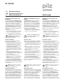
Das Erweiterungsmodul PNOZ mc3p darf
nur an ein Basisgerät (z. B. PNOZ m1p des
modularen Sicherheitssystems PNOZmulti)
angeschlossen werden. Es koppelt das
modulare Sicherheitssystem PNOZmulti an
den PROFIBUS-DP. Das modulare Sicherheitssystem PNOZmulti dient dem sicherheitsgerichteten Unterbrechen von Sicherheitsstromkreisen und ist bestimmt für den
Einsatz in:
• NOT-AUS-Einrichtungen
• Sicherheitsstromkreisen nach VDE 0113
Teil 1, 11/98 und EN 60204-1, 12/97
(z. B. bei beweglichen Verdeckungen)
The PNOZ mc3p expansion module may
only be connected to a base unit (e.g.
PNOZ m1p from the PNOZmulti modular
safety system). It connects the PNOZmulti
modular safety system to PROFIBUS-DP.
The PNOZmulti modular safety system is
used for the safety-related interruption of
safety circuits and is designed for use in:
• Emergency stop equipment
• Safety circuits in accordance with
VDE 0113 Part 1, 11/98 and EN 60204-1,
12/97 (e.g. on movable guards)
Le module d’extension PNOZ mc3p ne doit
être raccordé qu’à un appareil de base (par
exemple PNOZ m1p du système de sécurité
modulaire PNOZmulti). Il assure le couplage
du système de sécurité PNOZmulti au
PROFIBUS-DP. Le système de sécurité
modulaire PNOZmulti est conçu pour
interrompre en toute sécurité des circuits de
sécurité. Il est conçu pour être utilisé dans
les :
• Circuits d’arrêt d’urgence
• Circuits de sécurité selon les normes
VDE 0113-1, 11/98 et EN 60204-1, 12/97
(p. ex. pour protections mobiles)
Achtung! Das Erweiterungsmodul
PNOZ mc3p darf nicht für
sicherheitsgerichtete Funktionen
verwendet werden.
Caution! The PNOZ mc3p expansion module may not be used for
safety-related functions.
Attention ! Le module d’extension
PNOZ mc3p ne doit pas être utilisé
pour des fonctions de sécurité.
Zu Ihrer Sicherheit
For your safety
Pour votre sécurité
Beachten Sie nachfolgend aufgeführte
Sicherheitsbestimmungen:
• Installieren und nehmen Sie das Modul
nur dann in Betrieb, wenn Sie mit dieser
Betriebsanleitung und den geltenden
Vorschriften über Arbeitssicherheit und
Unfallverhütung vertraut sind.
• Verwenden Sie das Modul nur gemäß
seiner Bestimmung. Beachten Sie dazu
auch die Werte im Abschnitt "Technische
Daten".
• Halten Sie beim Transport, bei der
Lagerung und im Betrieb die Bedingungen
nach EN 60068-2-6, 04/95 ein (siehe
"Technische Daten").
• Öffnen Sie nicht das Gehäuse und
nehmen Sie auch keine eigenmächtigen
Umbauten vor.
• Schalten Sie bei Wartungsarbeiten
unbedingt die Versorgungsspannung ab.
Beachten Sie unbedingt die Warnhinweise in
den anderen Abschnitten dieser Anleitung.
Diese Hinweise sind optisch durch Symbole
hervorgehoben.
Please note the following safety regulations:
• Only install and commission the module if
you are familiar with both these instructions and the current regulations for health
and safety at work and accident prevention.
• Only use the module in accordance with
its intended purpose. Please also take
note of the values in the “Technical
details” section.
• Transport, storage and operating conditions should all conform to EN 60068-2-6,
04/95 (see “Technical details”).
• Do not open the housing or undertake any
unauthorised modifications.
• Always switch off the supply voltage when
carrying out maintenance work.
You must take note of the warnings given in
other sections of these operating instructions. These are highlighted visually through
the use of symbols.
Toutefois, vous êtes tenu de respecter les
prescriptions de sécurité suivantes :
• Vous n’installerez le module et ne le mettrez
en service qu’après vous être familiarisé
avec le présent manuel d’utilisation et les
prescriptions en vigueur sur la sécurité du
travail et la prévention des accidents.
• N’utilisez le module que conformément à
l’usage auquel il est destiné. À ce sujet,
respectez les valeurs indiquées dans les
“ Caractéristiques techniques ”.
• Observez les exigences de la norme EN
60068-2-6, 04/95 lors du transport, du
stockage et de l’utilisation de l’appareil (voir
les caractéristiques techniques).
• N’ouvrez pas le boîtier et n’effectuez pas de
modifications non autorisées.
• Lors de l’exécution de travaux de
maintenance, coupez impérativement la
tension d’alimentation.
Respectez impérativement les avertissements
dans les autres paragraphes du présent
manuel d’utilisation. Ces avertissements sont
signalés par des symboles visuels.
Wichtig: Beachten Sie die Sicherheitsbestimmungen, sonst erlischt
jegliche Gewährleistung.
Notice: Failure to keep to these safety
regulations will render the warranty
invalid.
Important : respectez les consignes de
sécurité, sinon la garantie devient
caduque.
Modulbeschreibung
Module description
Description du module
Der PROFIBUS-DP ist konzipiert für den
schnellen Datenaustausch in der Feldebene.
Das Erweiterungsmodul PNOZ mc3p ist ein
passiver Teilnehmer (Slave) des PROFIBUS-DP. Die Grundfunktionen der Kommunikation mit dem PROFIBUS-DP entsprechen den EN 50170. Die zentrale Steuerung
(Master) liest zyklisch die Eingangsinformationen von den Slaves und schreibt die
Ausgangsinformationen zyklisch an die
The PROFIBUS-DP is designed for fast data
exchange at the field level. The PNOZ mc3p
expansion module is a passive PROFIBUS-DP
subscriber (slave). The basic functions of
communication with PROFIBUS-DP
correspond to EN 50170. The central
controller (master) reads input information
from the slaves and writes output information to the slaves as part of each cycle. As
well as the cyclical transfer of usable data,
Le PROFIBUS-DP est conçu pour un
échange rapide de données sur le terrain. Le
module d’extension PNOZ mc3p est un
abonné passif (Slave) de PROFIBUS-DP.
Les fonctions de base de communication
avec le bus PROFIBUS-DP sont conformes
à la norme EN 50170. Le système central
(Master) lit cycliquement les informations
d’entrée sur les esclaves (Slaves) et écrit
cycliquement les informations de sortie dans
Slaves. Neben der zyklischen Nutzdatenübertragung verfügt der PROFIBUSDP auch über Funktionen für Diagnose und
Inbetriebnahme.
PROFIBUS-DP can also be used for
diagnostics and commissioning functions.
les esclaves. Outre la transmission cyclique
des données utiles, le bus PROFIBUS-DP est
également doté de fonctions de diagnostic et
de mise en service.
Modulmerkmale:
• konfigurierbar mit PNOZmulti Configurator
• Stationsadressen wählbar von 0 ... 99 mit
Drehschalter
• Statusanzeigen für Kommunikation mit
dem PROFIBUS-DP und von Fehlern
Module features:
• Can be configured using the PNOZmulti Configurator
• Station addresses from 0 ... 99, selected
via rotary switch
• Status indicators for communication with
PROFIBUS-DP and for errors
Caractéristiques du module :
• Paramétrable avec PNOZmulti Configurator
• Adresses des stations sélectionnables de
0 ... 99 par commutateurs rotatifs
• Affichage d’état pour la communication avec
le bus PROFIBUS-DP et pour les erreurs
Funktionsbeschreibung
Function description
Descriptif du fonctionnement
Arbeitsweise:
Die über den PROFIBUS-DP zu übertragenden Daten werden im PNOZmulti Configurator ausgewählt und konfiguriert.
Die Verbindung zwischen Basisgerät und
dem PNOZ mc3p erfolgt über eine Steckbrücke. Über diese Steckbrücke wird das
PNOZ mc3p auch mit Spannung versorgt.
Die Stationsadresse wird mit 2 Drehschaltern eingestellt. Nach Einschalten der
Versorgungsspannung oder einem Reset
des Sicherheitssystems PNOZmulti wird das
PNOZ mc3p automatisch konfiguriert und
gestartet.
Operation:
The data to be transferred via PROFIBUS-DP
are selected and configured in the
PNOZmulti Configurator.
The base unit and the PNOZ mc3p are
connected via a jumper. The PNOZ mc3p is
also supplied with voltage via this jumper.
The station address is set via 2 rotary
switches. After the supply voltage is
switched on or the PNOZmulti safety system
is reset, the PNOZ mc3p is configured and
started automatically.
Mode de travail :
Les données à transmettre par PROFIBUS-DP
sont sélectionnées et configurées dans le
Configurateur PNOZmulti.
Le raccordement entre l’appareil de base et le
PNOZ mc3p est réalisé au moyen d’un pont
enfichable. Celui-ci assure également
l’alimentation du PNOZ mc3p. L’adresse de
station est réglée au moyen de deux
commutateurs rotatifs. Après application de la
tension d’alimentation ou réinitialisation du
système de sécurité PNOZmulti, le module
PNOZ mc3p est automatiquement configuré et
démarré.
Funktionen:
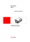
LEDs zeigen den Status des Erweiterungsmoduls PNOZ mc3p am PROFIBUS-DP an.
Functions:
LEDs indicate the status of the PNOZ mc3p
expansion module on PROFIBUS-DP.
Fonctions :
Les LED affichent l’état du module d’extension
PNOZ mc3p sur le PROFIBUS-DP.
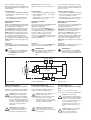
INFO
In der Online-Hilfe des PNOZmulti
Configurators ist die Konfiguration
des PNOZ mc3p ausführlich
beschrieben.
INFORMATION
The configuration of the PNOZ mc3p
is described in detail in the
PNOZmulti Configurator’s online
help.
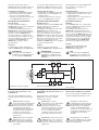
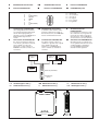
OFFLINE
ONLINE
PNOZ m1p
DC
0
56
0
2 34
x10
78
91
91
56
Controller
2 34
PROFIBUS DP
DC
78
INFORMATION
La configuration du module PNOZ
mc3p est décrite en détail dans l’aide
en ligne du Configurateur PNOZmulti.
x1
FAULT
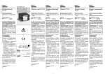
Internal wiring diagram
Schéma interne
PNOZ mc3p montieren
Installing the PNOZ mc3p
Installer PNOZ mc3p
Basisgerät und PNOZ mc3p verbinden
Connect the base unit and PNOZ mc3p
Raccorder l’appareil de base et le PNOZ
mc3p
Beachten sie vor der Montage des PNOZ
mc3p die folgenden Sicherheitshinweise:
Before installing the PNOZ mc3p, please
note the following safety guidelines:
Innenschaltbild
Achtung! Durch elektrostatische
Entladung können Bauteile des
Erweiterungsmoduls beschädigt
werden. Sorgen Sie für Entladung,
bevor Sie das Erweiterungsmodul
berühren, z. B. durch Berühren einer
geerdeten, leitfähigen Fläche oder
durch Tragen eines geerdeten
Armbands.
Caution! Electrostatic discharge can
damage components on the
expansion module. Ensure against
discharge before touching the
expansion module, e.g. by touching
an earthed, conductive surface or by
wearing an earthed armband.
Achtung! Montieren Sie das
Sicherheitssystem PNOZmulti in
einen Schaltschrank mit einer
Schutzart von mindestens IP54.
Caution! The PNOZmulti safety
system should be installed in a
control cabinet with a protection type
of at least IP54.
Observez les consignes de sécurité
suivantes lors du montage du PNOZ mc3p :
Attention ! Une décharge
électrostatique peut endommager
les éléments du module d’extension.
Veillez à vous décharger avant de
toucher le module d’extension, par
ex. en touchant une surface
conductrice mise à la terre ou en
portant un bracelet de mise à la
terre.
Attention ! Montez le système de
sécurité PNOZmulti dans une
armoire ayant un indice de
protection d’au moins IP 54.
Achtung! Montieren Sie das
Sicherheitssystem auf eine waagrechte Tragschiene. Andere
Einbaulagen können zur Zerstörung
des Sicherheitssystems führen.
Caution! Fit the safety system to a
horizontal DIN rail. Other mounting
positions could damage the safety
system.
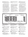
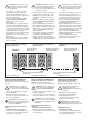
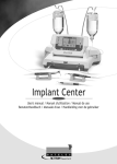
• Die Module werden mit Steckbrücken
verbunden. Auf der Geräterückseite des
Basisgeräts PNOZ m1p befinden sich
2 Stiftleisten. An der rechten Stiftleiste
befindet sich ein Abschlussstecker.
• Montieren Sie das Erweiterungsmodul
PNOZ mc3p links vom Basisgerät mit
der mitgelieferten Steckbrücke.
• Befestigen Sie das PNOZ mc3p mit Hilfe
der Rastelemente auf der Rückseite auf
einer Normschiene. Führen Sie das PNOZ
mc3p gerade auf die Normschiene, so
dass die Erdungsfedern am PNOZ mc3p
auf die Normschiene gedrückt werden.
• Um die EMV-Anforderungen einzuhalten,
muss die Normschiene mit dem Schaltschrankgehäuse niederohmig verbunden
sein.
• Zwischen dem PNOZ mc3p und externen
Wärmequellen muss mind. 20 mm
Abstand eingehalten werden.
• The modules are linked via jumpers. There
are 2 pin connectors on the rear of the
PNOZ m1p base unit. The right-hand pin
connector contains a terminating plug.
• Install the PNOZ mc3p expansion module
to the left of the base unit using the
jumper supplied.
• Use the notches on the back of the
PNOZ mc3p to attach it to a DIN rail.
Connect the PNOZ mc3p to the DIN rail in
an upright position so that the earthing
springs on the PNOZ mc3p are pressed on
to the DIN rail.
• To comply with EMC requirements, the
DIN rail must have a low impedance
connection to the control cabinet housing.
• A minimum distance of 20 mm must be
maintained between the PNOZ mc3p and
external heat sources.
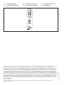
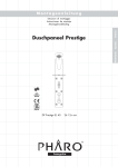
PNOZ mc3p links vom Basisgerät
montieren!
Install the PNOZ mc3p to the left of the
base unit!
Basisgerät/
Base unit/
Appareil de base
PNOZ mc3p
PROFIBUS
• Les modules sont reliés par des cavaliers
de pontage. La face arrière de l’appareil
de base PNOZ m1p comporte 2 broches.
Une fiche de terminaison est branchée sur
la broche de droite.
• Montez le module d’extension PNOZ mc3p
à gauche de l’appareil de base au
moyen du pont enfichable fourni.
• Accrochez le PNOZ mc3p sur un rail DIN à
l’aide des ergots à l’arrière de l’appareil.
Installez le PNOZ mc3p droit sur le rail DIN
de sorte que les ressorts de mise à la terre
sur le PNOZ mc3p reposent sur le rail DIN.
• Pour respecter les exigences CEM, le rail
DIN doit être relié par une liaison à basse
impédance au corps de l’armoire.
• Une distance d’au moins 20 mm doit être
respectée entre le PNOZ mc3p et les
sources de chaleur externes.
Monter le PNOZ mc3p à gauche de
l’appareil de base !
Erweiterungsmodul 1/
Expander module 1/
Module d'extension 1
774 640: Steckbrücke/Link/
Cavalier de pontage
PNOZ mc3p montieren
Attention ! Montez le système de
sécurité sur un profilé support
horizontal. D’autres positions de
montage pourraient aboutir à une
destruction du système de sécurité.
Erweiterungsmodul 8/
Expander module 8/
Module d'extension 8
779 110: Abschlussstecker/Terminator/
Fiche de terminaison
Installing the PNOZ mc3p
Installer PNOZ mc3p
PNOZ mc3p inbetriebnehmen
Commissioning the PNOZ mc3p
Mettre en service le PNOZ mc3p
Inbetriebnahme vorbereiten:
Beachten Sie bei der Vorbereitung der
Inbetriebnahme:
Preparing for commissioning:
Please note the following when preparing to
commission the unit:
Préparation de la mise en service :
Tenez compte des points suivants lors de la
préparation de la mise en service :
Achtung! Das Erweiterungsmodul
PNOZ mc3p nur im spannungslosen Zustand ziehen und stecken.
• Verwenden Sie nur Metallstecker oder
metallisierte Kunststoffstecker.
• Die Verbindungskabel zu den Schnittstellen müssen paarweise verdrillt und
abgeschirmt sein.
Wichtig: Beachten Sie bei der
Installation unbedingt die "Aufbaurichtlinien" der PROFIBUS-Nutzerorganisation.
Betriebsbereitschaft herstellen:
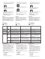
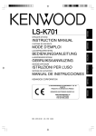
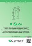
• Stationsadresse einstellen
Die Stationsadresse des PNOZ mc3p wird
mit zwei Drehschaltern x1 und x10 von
0 ... 99 (dezimal) eingestellt.
Caution! Only connect and disconnect
the PNOZ mc3p expansion module
when the supply voltage is
switched off.
• Only use metal plugs or metallised plastic
plugs.
• Twisted pair, screened cable must be used
to connect the interfaces.
Important: When installing, you must
refer to the set-up guidelines published
by the PROFIBUS User Group.
Preparing the unit for operation:
• Setting the station address
The station address of the PNOZ mc3p is
set between 0 ... 99 (decimal) via two
rotary switches x1 and x10.
Attention ! Le module d’extension
PNOZ mc3p ne doit être mis en place
ou retiré que lorsqu’il est hors tension.
• Utilisez exclusivement des connecteurs
métalliques ou des connecteurs plastiques
métallisés.
• Le câble des raccordements aux interfaces
doit être torsadé par paires et être blindé.
Important : lors de l’installation,
respectez impérativement les "directives
de montage" de l’organisation des
utilisateurs de PROFIBUS.
Mise en route :
• Régler l’adresse de station
L’adresse de station du PNOZ mc3p est
réglée au moyen de deux commutateurs
rotatifs x1 et x10 de 0 ... 99 (décimal).
0
56
0
0
56
0
56
0
56
2 34
0
78
2 34
2 34
56
x10
- Réglez l’unité de l’adresse sur le
commutateur rotatif inférieur x1
(dans notre exemple "6").
x1
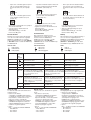
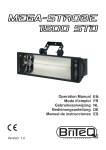
Station address 36 is set in the diagrams
as an example.
• Connect the supply voltage to the base
unit:
Terminals 24 V and A1 (+): + 24 V DC
Terminals 0 V and A2 (-): 0 V
78
91
x1
2 34
2 34
In den Abbildungen ist als Beispiel die
Stationsadresse 36 eingestellt.
• Legen Sie die Versorgungspannung an
das Basisgerät:
Klemmen 24 V und A1 (+): + 24 V DC
Klemmen 0 V und A2 (-): 0 V
x10
- On the lower rotary switch x1, set the
ones digit for the address (“6” in the
example).
78
- Réglez les dizaines de l’adresse sur le
commutateur rotatif supérieur x10, au
moyen d’un petit tournevis (dans notre
exemple "3").
91
x10
91
91
78
78
91
91
78
- Stellen Sie am unteren Drehschalter
x1 die Einerstelle der Adresse ein (im
Beispiel "6").
56
- On the upper rotary switch x10, use a
small screwdriver to set the tens digit for
the address (“3” in the example).
2 34
- Stellen Sie am oberen Drehschalter x10
mit einem kleinen Schraubendreher die
Zehnerstelle der Adresse ein (im
Beispiel "3").
x1
Les illustrations présentent comme exemple
une adresse de station égale à 36.
• Appliquez la tension d’alimentation sur
l’appareil de base :
Bornes 24 V et A1 (+) : + 24 V DC
Bornes 0 V et A2 (-) : 0 V
Betrieb
Operation
Exploitation
Nach Einschalten der Versorgungsspannung
oder einem Reset des Sicherheitssystems
PNOZmulti wird das PNOZ mc3p automatisch konfiguriert und gestartet. Die LEDS
"ONLINE" und "OFFLINE" zeigen den
Status des PNOZ mc3p am PROFIBUS-DP
an.
After the supply voltage is switched on or the
PNOZmulti safety system is reset, the
PNOZ mc3p is configured and started
automatically. The LEDs “ONLINE” and
“OFFLINE” indicate the status of the PNOZ
mc3p at PROFIBUS-DP.
Après application de la tension d’alimentation
ou une réinitialisation du système de sécurité
PNOZmulti, le module PNOZ mc3p est
automatiquement configuré et démarré. Les
LEDS "ONLINE" et "OFFLINE" indiquent l’état
du PNOZ mc3p sur bus PROFIBUS-DP.
LED-Anzeige
LED aus
LED leuchtet
LED blinkt
LEDs
LEDs de visualisation
LED éteinte
LED allumée
LED clignote
LED
LED off
LED on
LED flashes
LED-Zustand/ Bedeutung
LED status/
état de la
LED
ONLINE/
EN LIGNE
OFFLINE
FAULT
1 Hz
2 Hz
4 Hz
Key
Signification
PNOZ mc3p Online,
Datenaustausch möglich
PNOZ mc3p online, data exchange
possible
PNOZ mc3p en ligne, échange de
données possible
PNOZ mc3p nicht Online
PNOZ mc3p not online
PNOZ mc3p n’est pas en ligne
PNOZ mc3p Offline,
Datenaustausch nicht möglich
PNOZ mc3p offline, data exchange
not possible
PNOZ mc3p hors ligne, échange de
données impossible
PNOZ mc3p nicht Offline
PNOZ mc3p not offline
PNOZ mc3p n’est pas en ligne
Konfigurationsfehler, Länge der Einund/oder Ausgangsdaten bei der
Initialisierung des PNOZ mc3p
entsprechen nicht der Konfiguration
Configuration error, length of input
and/or output data during
initialisation of the PNOZ mc3p
does not correspond to the
configuration
Erreur de configuration, la longueur
des données d’entrée et/ou de
sortie ne correspondent pas à la
configuration lors de l’initialisation
du PNOZ mc3p
Konfigurationsfehler, Länge/Inhalt
der Projektierungsdaten bei der
Initialisierung des PNOZ mc3p
entsprechen nicht der Konfiguration
Configuration error, length/contents
of configuration data during
initialisation of the PNOZ mc3p does
not correspond to the configuration
Erreur de configuration, la longueur/le
contenu des données du projet ne
correspondent pas à la configuration
lors de l’initialisation du PNOZ mc3p
Fehler bei der Initialisierung des
PROFIBUS
Error when initialising PROFIBUS
Erreur d’initialisation du PROFIBUS
kein Fehler
No error
Aucune erreur
Ausgangsdaten
Output data
Données de sortie
Die Ausgangsdaten sind wie folgt aufgebaut:
• Byte 0 bis 2 (24 Ausgänge):
konfigurierbar im PNOZmulti Configurator
mit Ausgängen von Logikelementen,
Zeitgliedern, Ereigniszählern, Anschlusspunkten oder Eingängen des PNOZmulti.
Die Zuordnung der Ausgänge im
PNOZmulti Configurator zu den PROFIBUS-Ausgangsdaten entnehmen Sie der
Tabelle im folgenden Abschnitt.
• Byte 3:
Bit 0 ... 4: LED-Zustände des PNOZmulti
- Bit 0: OFAULT
- Bit 1: IFAULT
- Bit 2: FAULT
- Bit 3: DIAG
- Bit 4: RUN
Bit 5: Datenaustausch findet statt
The output data are structured as follows:
• Byte 0 to 2 (24 outputs):
Can be configured in the PNOZmulti Configurator
with outputs from logic elements, time
elements, event counters, connection points
or inputs on the PNOZmulti. The allocation
of outputs in the PNOZmulti Configurator to
the PROFIBUS output data can be found in
the table in the following section.
• Byte 3:
Bit 0 ... 4: Status of LEDs on the PNOZmulti
- Bit 0: OFAULT
- Bit 1: IFAULT
- Bit 2: FAULT
- Bit 3: DIAG
- Bit 4: RUN
Bit 5: Data are being exchanged
Les données de sortie sont structurées de la
manière suivante :
• Octets 0 à 2 (24 sorties) :
configurables dans le Configurateur PNOZmulti
avec des sorties d’éléments logiques, des
temporisateurs, des compteurs d’éléments, des
points de raccordement ou des entrées du
PNOZmulti. Vous pouvez consulter l’affectation
des sorties du Configurateur PNOZmulti aux
données de sorties PROFIBUS dans le tableau
de la section suivante.
• Octet 3 :
Bit 0 ... 4 : état des LED du PNOZmulti
- Bit 0 : OFAULT
- Bit 1 : IFAULT
- Bit 2 : FAULT
- Bit 3 : DIAG
- Bit 4 : RUN
Bit 5 : l´échange de données est en cours
Zuordnung der Ausgänge im PNOZmulti
Configurator zu den PROFIBUS-Ausgangsdaten
Allocation of outputs in the
PNOZmulti Configurator to the PROFIBUS
output data
Ausgänge PNOZmulti Configurator/Outputs on PNOZmulti Configurator/Sorties du Configurateur PNOZmulti
Ausgangsdaten PROFIBUS-DP/PROFIBUS-DP output data/Données de sortie
PROFIBUS-DP
Affectation des sorties dans le
Configurateur PNOZmulti aux données de
sortie PROFIBUS
O0 ... O7
O8 ... O15
O16 ... O23
Byte/Octet 0 : Byte/Octet 1 : Byte/Octet 2 :
Bit 0 ... 7
Bit 0 ... 7
Bit 0 ... 7
PROFIBUS-DP-Schnittstelle
PROFIBUS-DP interface
Interface PROFIBUS-DP
Für die Verbindung zum PROFIBUS-DP
verfügt das PNOZ mc3p über einen 9poligen
Sub-D-Buchsenstecker. Eine ausführliche
Beschreibung der PROFIBUS-DP-Schnittstelle finden Sie in der "Aufbaurichtlinie
PROFIBUS-DP" der PROFIBUS-Nutzerorganisation.
The PNOZ mc3p has a female 9-pin Sub-D
connector for connection to PROFIBUS-DP.
A detailed description of the PROFIBUS-DP
interface can be found in the PROFIBUS-DP
set-up guidelines published by the
PROFIBUS User Group.
Le module PNOZ mc3p est doté d’un
connecteur mâle Sub-D à 9 broches pour le
raccordement au bus PROFIBUS-DP. Vous
trouverez une description complète de
l’interface PROFIBUS-DP dans les
"Directives de montage du PROFIBUS-DP"
de l’organisation d’utilisateurs PROFIBUS.
Auf den beiden letzten Seiten finden Sie ein
Anschlussbeispiel, die Anschlussbelegung,
die Belegung der PROFIBUS-DP-Schnittstelle und die Abmessungen des Geräts.
The last two pages contain a connection
example, the pin configuration, the configuration of the PROFIBUS-DP interface and
the unit’s dimensions.
Vous trouverez sur les deux dernières pages
un exemple de raccordement, le brochage
de l’interface PROFIBUS-DP ainsi que les
dimensions de l’appareil.
Technische Daten
Technical details
Caractéristiques techniques
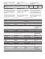
Elektrische Daten
Versorgungsspannung (UB) über
Basisgerät
Leistungsaufnahme bei UB
Zeiten
Überbrückung von
Spannungseinbrüchen
PROFIBUS-DP
Anwendungsbereich
Electrical data
Supply voltage (UB) via base unit
Power consumption at UB
Times
Supply interruption before deenergisation
PROFIBUS-DP
Application range
Données électriques
Tension d’alimentation (UB) par
l’appareil de base
Consommation pour UB
Temps
Temps de maintien si coupures de
tension
PROFIBUS-DP
Domaine d’utilisation
Gerätetyp
Statusanzeige
Stationsadresse
Übertragungsrate
Anschluss
Device type
Status display
Station address
Transmission rate
Connection
Type d’appareil
Visualisation de l’état
Adresse station
Vitesse de transmission
Raccordements
Galvanische Trennung
Prüfspannung
Galvanic isolation
Test voltage
Séparation galvanique
Tension de contrôle
Umweltdaten
Klimabeanspruchung
EMV
Schwingungen nach
Frequenz
Amplitude
Umgebungstemperatur
Lagertemperatur
Mechanische Daten
Schutzart
Einbauraum (z. B. Schaltschrank)
Gehäuse
Klemmenbereich
Gehäusematerial
Front
Gehäuse
Abmessungen H x B x T
Environmental data
Climatic suitability
EMC
Vibration to
Frequency
Amplitude
Ambient temperature
Storage temperature
Mechanical data
Protection type
Mounting (e.g. control cabinet)
Housing
Terminals
Housing material
Front panel
Housing
Dimensions H x W x D
Gewicht
Weight
Environnement
Sollicitations climatiques
DIN IEC 60068-2-3, 12/86
CEM
EN 61000-6-2, 10/01
Vibrations selon
EN 60068-2-6, 04/95
Fréquence
10 ... 55 Hz
Amplitude
0,35 mm
Température d’utilisation
0 ... + 55 °C
Température de stockage
-25 ... + 70 °C
Données mécaniques
Indice de protection
Lieu d’implantation (p. ex. armoire) IP54
Boîtier
IP20
Borniers
IP20
Matériau du boîtier
Face avant
ABS UL 94 V0
Boîtier
PPO UL 94 V0
Dimensions H x L x P
94 x 22,5 x 119 mm
(3.70" x 0.88" x 4.69")
Poids
140 g
24 V DC
max. 2,5 W
min. 20 ms
nicht sicherheitsgerichtete
Anwendungen/non-safetyrelated applications/pour
les applications ne touchant
pas à la sécurité
Slave
LED
0 ... 99
9,6 kBit/s ... 12 MBit/s
9poliger Sub-D-Buchsenstecker/female 9-pin
Sub-D connector /fiche
Sub-D femelle à 9 pôles
ja/yes/oui
500 V AC
21 010-02
4E
Instrucciones de uso
4I
Istruzioni per luso
4NL Gebruiksaanwijzing
PNOZ mc3p
Módulo de ampliación PNOZ mc3p
PROFIBUS
Modulo di espansione PNOZ mc3p
PROFIBUS
Uitbreidingsmodule PNOZ mc3p
PROFIBUS
El módulo de ampliación PNOZ mc3p puede
ser conectado sólo a un dispositivo básico
(p. ej. PNOZ m1p del sistema de seguridad
modular PNOZmulti). Acopla el sistema
modular de seguridad PNOZmulti al
PROFIBUS-DP. El sistema de seguridad
modular PNOZmulti sirve para la interrupción
orientada a la seguridad de circuitos eléctricos y
está diseñado para emplearse en:
• Dispositivos de PARADA DE EMERGENCIA
• Circuitos de seguridad según VDE 0113
parte 1, 11/98 y EN 60204-1, 12/97
(p. ej. con cubiertas móviles)
Il modulo di espansione PNOZ mc3p può
essere collegato soltanto ad un dispositivo base
(ad es. PNOZ m1p del sistema di sicurezza
modulare PNOZmulti). Con questo dispositivo, il
sistema di sicurezza modulare PNOZmulti viene
collegato al PROFIBUS-DP. Il sistema di
sicurezza modulare PNOZmulti consente
l’interruzione sicura dei circuiti di sicurezza ed è
concepito per essere utilizzato in:
• dispositivi di arresto di emergenza
• circuiti elettrici di sicurezza conformi alla
norma VDE 0113 Parte 1, 11/98 e EN 60204-1,
12/97 (p. es. in caso di coperture mobili)
De uitbreidingsmodule PNOZ mc3p mag
alleen op een basismodule (b.v. PNOZ m1p
van het modulaire veiligheidssysteem
PNOZmulti) aangesloten worden. De module
koppelt het modulaire veiligheidssysteem
PNOZmulti aan de PROFIBUS-DP. Het
modulaire veiligheidssysteem PNOZmulti
dient om veiligheidscircuits veilig te onderbreken en is bestemd voor gebruik in:
• noodstopvoorzieningen
• veiligheidscircuits volgens VDE 0113 deel 1,
11/98 en EN 60204-1, 12/97
(b.v. bij beweegbare afschermingen)
Attenzione! Il modulo di espansione
PNOZ mc3p non può essere
utilizzato per funzioni di sicurezza.
Let op! De uitbreidingsmodule
PNOZ mc3p mag niet voor veiligheidsgerelateerde functies gebruikt worden.
¡Atención! El módulo de ampliación
PNOZ mc3p no puede utilizarse para
funciones orientadas a la seguridad.
Para su propia seguridad
Per la Vostra sicurezza
Voor uw veiligheid
Tenga en cuenta las siguientes
prescripciones de seguridad:
• Instale y ponga en funcionamiento el
módulo sólo si usted está familiarizado con
estas instrucciones de uso y con las
prescripciones vigentes relativas a la
seguridad en el trabajo y a la prevención
de accidentes.
• Utilice el módulo solo para la aplicación a
la que está destinado. Para ello tenga en
cuenta los valores indicados en la sección
"Datos técnicos".
• Durante el transporte, almacenaje y
funcionamiento hay que atenerse a las
condiciones conforme a EN 60068-2-6, 04/
95 (ver "Datos técnicos").
• No abra la carcasa ni lleve a cabo
modificaciones por cuenta propia.
• Desconecte siempre la tensión de
alimentación durante los trabajos de
mantenimiento.
Es estrictamente necesario que observe las
indicaciones de advertencia en las otras
secciones de estas instrucciones. Esas
indicaciones están resaltadas ópticamente
por medio de símbolos.
È necessario osservare le seguenti norme
di sicurezza:
• Il modulo può venire installato e messo in
funzione solo se si conoscono bene le
presenti istruzioni per l’uso e le
disposizioni vigenti relative alla sicurezza
di lavoro e all’antinfortunistica.
• Utilizzare il modulo solo in base alle
disposizioni ad esso riferite. Osservare
anche i valori indicati al paragrafo "Dati
tecnici".
• Durante il trasporto, l’immagazzinamento
e il funzionamento attenersi alle
condizioni prescritte dalla norma
EN 60068-2-6, 04/95 (v. "Dati tecnici").
• Non aprire la custodia e non apportare
modifiche non autorizzate.
• Assicurarsi di aver interrotto la tensione
di alimentazione prima di procedere ai
lavori di manutenzione.
Osservare le avvertenze riportate nelle altre
sezioni delle presenti istruzioni. Queste
indicazioni sono evidenziate da appositi
simboli.
Neem de volgende veiligheidsvoorschriften
in acht:
• Installeer en neem de module alleen in
gebruik, als u vertrouwd bent met deze
gebruiksaanwijzing en de geldende
voorschriften op het gebied van arbeidsveiligheid en ongevallenpreventie.
• Gebruik de module alleen waarvoor hij
bestemd is. Neem daartoe ook de
waarden in de paragraaf „Technische
gegevens” in acht.
• Neem bij transport, opslag en in bedrijf de
richtlijnen volgens EN 60068-2-6, 04/95 in
acht (zie „Technische gegevens”).
• Open de behuizing niet en bouw het
apparaat ook niet eigenmachtig om.
• Schakel bij onderhoudswerkzaamheden
altijd de voedingsspanning uit.
Neem beslist de waarschuwingen in de
andere paragrafen in deze gebruiksaanwijzing in acht. Deze waarschuwingen zijn met
symbolen geaccentueerd.
Importante: observe las prescripciones de seguridad, en caso contrario
se extingue toda garantía.
Importante: osservare le disposizioni per
la sicurezza, poiché in caso contrario
decadrà qualsiasi diritto di garanzia.
Belangrijk: Neem de veiligheidsvoorschriften in acht, anders vervalt
elke garantie.
Descripción del módulo
Descrizione del modulo
Modulebeschrijving
El PROFIBUS-DP está concebido para el
rápido intercambio de datos a nivel de campo.
El módulo de ampliación PNOZ mc3p es un
participante pasivo (esclavo) del PROFIBUSDP. Las funciones básicas de la comunicación
con el PRIFIBUS-DP se corresponden con
EN 50170. El control central (master) lee
cíclicamente la información de entrada de los
esclavos y escribe cíclicamente la información
de salida a los esclavos. Además de la
Il PROFIBUS-DP è stato concepito per
consentire uno rapido scambio dei dati a
livello di campo. Il modulo di espansione
PNOZ mc3p rappresenta un utente passivo
(slave) del PROFIBUS-DP. Le funzioni base
di comunicazione con il PROFIBUS-DP sono
conformi alla norma EN 50170. Il dispositivo
di controllo centrale (master) legge ciclicamente le informazioni in ingresso dagli slave
e scrive ciclicamente le informazioni in uscita
PROFIBUS-DP is ontworpen voor het snel
uitwisselen van data op veldniveau. De
uitbreidingsmodule PNOZ mc3p is een
passieve deelnemer (slave) van PROFIBUSDP. De basisfuncties van de communicatie
met PROFIBUS-DP voldoen aan EN 50170.
De centrale besturing (master) leest cyclisch
de ingangsinformatie van de slaves en
schrijft de uitgangsinformatie cyclisch naar
de slaves. Naast het cyclisch oversturen van
transmisión cíclica de datos útiles, el
PROFIBUS-DP dispone también de funciones
para el diagnóstico y la puesta en marcha.
verso gli slave. Oltre alla trasmissione ciclica
dei dati utili, il PROFIBUS-DP dispone anche
delle funzioni di diagnosi e messa in funzione.
gebruiksgegevens beschikt PROFIBUS-DP
ook over functies voor diagnose en
ingebruikneming.
Características del módulo:
• Configurable con PNOZmulti Configurator
• Direcciones de estación seleccionables
de 0 ... 99, con conmutador giratorio
• Indicadores de estado para la comunicación
con el PROFIBUS-DP y para errores
Caratteristiche del modulo:
• Configurabile con PNOZmulti Configurator
• Indirizzi stazione selezionabili da 0 ... 99
mediante selettore.
• Visualizzazioni di stato per la comunicazione con il PROFIBUS-DP e di errore.
Modulekenmerken:
• Configureerbaar met PNOZmulti Configurator
• Stationsadressen te kiezen van 0 ... 99
met draaischakelaar
• Statusweergave voor communicatie met
PROFIBUS-DP en storingen
Descripción del funcionamiento
Descrizione del funzionamento
Functiebeschrijving
Modo de trabajo:
Los datos a transmitir mediante el
PROFIBUS-DP se seleccionan y configuran en
el PNOZmulti Configurator.
La conexión entre el dispositivo básico y el
PNOZ mc3p tiene lugar mediante un puente
insertable. A través de ese puente también se
alimenta con tensión al PNOZ mc3p. La
dirección de estación se configura con dos
conmutadores giratorios. Después de conectar
la tensión de alimentación o de un reset del
sistema de seguridad PNOZmulti, el
PNOZ mc3p se configura y arranca
automáticamente.
Modalità di lavoro:
I dati da trasmettere tramite PROFIBUS-DP
vengono selezionati e configurati nel
PNOZmulti Configurator.
Il collegamento tra il dispositivo base ed il
PNOZ mc3p avviene attraverso un
ponticello. Attraverso lo stesso ponticello
viene anche alimentata la tensione per il
PNOZ mc3p. L’indirizzo della stazione viene
impostato con 2 selettori. Dopo l’inserimento
della tensione di alimentazione o in seguito
ad un reset del sistema di sicurezza
PNOZmulti, il PNOZ mc3p viene configurato
e avviato automaticamente.
Werking:
De via PROFIBUS-DP over te dragen data
worden in PNOZmulti Configurator geselecteerd en geconfigureerd.
De verbinding tussen basismodule en
PNOZ mc3p wordt gerealiseerd via een
busconnector. Via deze busconnector vindt
ook de voeding van PNOZ mc3p plaats. Het
stationsadres wordt met 2 draaischakelaars
ingesteld. Na inschakelen van de voedingsspanning of een reset van het veiligheidssysteem PNOZmulti wordt PNOZ mc3p
automatisch geconfigureerd en gestart.
Funciones:
Los LEDs indican el estado del módulo de
ampliación PNOZ mc3p en el PROFIBUS-DP.
Funzioni:
I LED indicano lo stato del modulo di
espansione PNOZ mc3p nel PROFIBUS-DP.
Functies:
De status van de uitbreidingsmodule
PNOZ mc3p wordt met LED’s op
PROFIBUS-DP aangegeven.
INFORMACIÓN
En la ayuda online del PNOZmulti
Configurator se describe detalladamente cómo configurar el PNOZ mc3p.
INFORMAZIONE
Nella guida Online del PNOZmulti
Configurator la configurazione del
PNOZ mc3p è descritta in maniera
dettagliata.
OFFLINE
ONLINE
0
56
0
78
91
91
56
Controller
2 34
x10
Esquema de conexiones internas
PNOZ m1p
DC
2 34
PROFIBUS DP
DC
78
INFO
In de online hulp van PNOZmulti
Configurator is de configuratie van
PNOZ mc3p uitvoerig beschreven.
x1
FAULT
Schema di collegamento interno
Intern schema
Montar el PNOZ mc3p
Montaggio del PNOZ mc3p
PNOZ mc3p monteren
Conectar el dispositivo básico con
el PNOZ mc3p
Collegamento del dispositivo base con il
PNOZ mc3p
Basismodule en PNOZ mc3p verbinden
Antes de montar el PNOZ mc3p, tenga en
cuenta las siguientes indicaciones de seguridad:
Prima di procedere al montaggio del
PNOZ mc3p, osservare le seguenti
indicazioni di sicurezza:
Neem voor de montage van PNOZ mc3p de
volgende veiligheidsaanwijzingen in acht:
¡Atención! Debido a descarga
electrostática pueden resultar dañados
componentes del módulo de ampliación. Antes de entrar en contacto con
el módulo hay que descargar la
electricidad estática del propio cuerpo,
por ejemplo tocando una superficie
conductora con toma de tierra o
llevando puesta una muñequera con
puesta a tierra.
Attenzione! Le scariche
elettrostatiche possono danneggiare
i componenti del modulo di
espansione. Scaricare l’energia
elettrostatica dal proprio corpo prima
di toccare il modulo di espansione,
per es. toccando una superficie
conduttiva collegata a terra, oppure
indossando un bracciale a massa.
Let op! Door elektrostatische
ontlading kunnen componenten van
de uitbreidingsmodule beschadigd
worden. Zorgt u voor ontlading
voordat u de uitbreidingsmodule
aanraakt, b.v. door het aanraken van
een geaard, geleidend vlak of door
het dragen van een geaarde
armband.
¡Atención! El sistema de seguridad
PNOZmulti tiene que ser montado
dentro de un armario de distribución
con un grado de protección de IP54
como mínimo.
Attenzione! Il sistema di sicurezza
PNOZmulti deve essere montato in
un armadio elettrico con un tipo di
protezione corrispondente almeno al
grado IP 54.
Let op! Monteer het veiligheidssysteem PNOZmulti in een schakelkast met een beschermingsgraad
van minimaal IP54.
¡Atención! Monte el sistema en una
guía portadora horizontal. Si monta el
dispositivo en otra posición, podría
resultar dañado.
• Los módulos se conectan con puentes
insertables. En la parte posterior del
dispositivo básico PNOZ m1p hay dos
regletas de clavijas. En la de la derecha se
encuentra un terminador.
• Monte el módulo de ampliación PNOZ
mc3p a la izquierda del dispositivo
básico, con el puente insertable
suministrado.
• Fije el PNOZ mc3p con ayuda del elemento
de encaje a la guía normalizada de la parte
trasera. Coloque el PNOZ mc3p, derecho,
en la guía normalizada, de tal manera que
los resortes de puesta a tierra en el PNOZ
mc3p hagan presión sobre la guía.
• Para cumplir con los requerimientos CEM,
la guía debe estar unida, con baja
impedancia, con la carcasa del armario de
distribución.
• Entre el PNOZ mc3p y la fuente externa
de calor debe haber una distancia de 20
mm como mínimo.
Montar el PNOZ mc3p a la izquierda
del dispositivo básico
Let op! Monteer het veiligheidssysteem
op een horizontale draagrail. Andere
inbouwposities kunnen ertoe leiden
dat het veiligheidssysteem defect
raakt.
• I moduli vengono collegati con l’ausilio di
ponticelli. Sul retro del dispositivo base
PNOZm1p sono previste 2 spine. Sulla
spina destra è applicato un connettore
terminale.
• Montare il modulo di espansione PNOZ
mc3p a sinistra del dispositivo base con
il ponticello fornito.
• Fissare il PNOZ mc3p su una guida con
l’aiuto dei dispositivi di incastro situati sul
retro. Applicare il PNOZ mc3p diritto sulla
guida, in modo che le molle di messa a
terra previste sul PNOZ mc3p facciano
presa sulla guida.
• Per rispettare i requisiti di compatibilità
elettromagnetica, la guida deve essere
collegata alla custodia dell’armadio
elettrico con bassa resistenza ohmica.
• Il PNOZ mc3p deve trovarsi ad almeno 20
mm di distanza da eventuali fonti di calore.
• De modulen worden met busconnectoren
verbonden. Op de achterzijde van de
basismodule PNOZ m1p bevinden er zich
2 pennenstroken. Op de rechter pennenstrook bevindt zich een afsluitconnector.
• Monteer de uitbreidingsmodule PNOZ
mc3p links van de basismodule met de
meegeleverde busconnector.
• Bevestig PNOZ mc3p op een DIN-rail met
behulp van de relaisvoet op de achterzijde.
Plaats het PNOZ mc3p recht op de DINrail, zodat de aardingsveren van het PNOZ
mc3p op de DIN-rail gedrukt worden.
• Om te voldoen aan de EMC-eisen, moet
de DIN-rail laagohmig met de schakelkastbehuizing verbonden zijn.
• Tussen de PNOZ mc3p en externe
warmtebronnen moet ten minste 20 mm
afstand worden aangehouden.
Montare il PNOZ mc3p a sinistra del
dispositivo base
Dispositivo básico/
Dispositivo base/
Basismodule
PNOZ mc3p
PROFIBUS
Montar el PNOZ mc3p
Attenzione! Montare il sistema di
sicurezza su una guida orizzontale.
Posizioni di montaggio differenti
possono provocare la distruzione del
sistema di sicurezza.
774 640: Puente insertable/Ponticello/
Busconnector
Montaggio del PNOZ mc3p
PNOZ mc3p links van de basismodule
monteren!
Módulo de ampliación 1/
Modulo di espansione 1/
Uitbreidingsmodule 1
Módulo de ampliación 8/
Modulo di espansione 8/
Uitbreidingsmodule 8
779 110: Terminador/Connettore terminale/
Afsluitstekker
PNOZ mc3p monteren
Puesta en marcha del PNOZ mc3p
Messa in funzione del PNOZ mc3p
PNOZ mc3p in gebruik nemen
Preparación de la puesta en marcha:
Al preparar la puesta en marcha hay que tener
en cuenta:
Preparazione della messa in funzione:
Durante la preparazione alla messa in
funzione occorre considerare quanto segue:
Ingebruikneming voorbereiden:
Neem bij de voorbereiding van de ingebruikneming de volgende zaken in acht:
¡Atención! Extraer e insertar el
módulo de ampliación PNOZ mc3p
sólo cuando se encuentre sin tensión.
• Utilice sólo clavijas metálicas o clavijas de
plástico metalizadas.
• Los cables de conexión que van a los
interfaces tienen que estar entrelazados de
dos en dos y apantallados.
Importante: durante la instalación se
deben tener en cuenta las "Directivas de
montaje" de la PNO (organización de
usuarios de PROFIBUS).
Preparar el dispositivo para su funcionamiento:
• Configurar la dirección de estación
La dirección de estación del PNOZ mc3p se
configura con dos conmutadores giratorios
x1 y x10 de 0 ... 99 (decimal).
Attenzione! Inserire e disinserire il
modulo di espansione PNOZmc3p
soltanto in assenza di tensione.
• Utilizzare soltanto spine in metallo o spine
in plastica metallizzate.
• Il cavo di collegamento con le interfacce
deve essere twistato a coppie e schermato.
Importante: Nel corso dell’installazione,
osservare scrupolosamente le "Direttive
di montaggio" dell’organizzazione utenti
PROFIBUS.
Preparazione al funzionamento del
dispositivo:
• Impostare l’indirizzo della stazione
L’indirizzo della stazione del PNOZ mc3p
viene impostata con due selettori x1 e x10 da
0 ... 99 (decimale).
Let op! De uitbreidingsmodule
PNOZ mc3p alleen in de
spanningsloze toestand uittrekken
en plaatsen.
• Gebruik alleen metalen stekkers of
gemetalliseerde kunststofstekkers.
• De verbindingskabels met de
communicatiepoorten moeten per paar
getwist en afgeschermd zijn.
Belangrijk: Neem bij de installatie
beslist de „Opbouwrichtlijnen” van de
PROFIBUS-gebruikersorganisatie in acht.
Bedrijfsklaar maken:
• Stationadres instellen
Het stationadres van PNOZ mc3p wordt
met twee draaischakelaars x1 en x10 van
0 ... 99 (decimaal) ingesteld.
78
2 34
2 34
2 34
En las figuras está ajustada como ejemplo la
dirección de estación 36.
• Conecte la tensión de alimentación al
dispositivo básico:
Bornes 24 V y A1 (+): + 24 V CC
Bornes 0 V y A2 (-): 0 V
0
x1
Nelle figure è descritta come esempio
l’impostazione dell’indirizzo 36.
• Applicare la tensione di alimentazione al
dispositivo base:
Morsetti 24 V e A1 (+): +24 V DC
Morsetti 0 V e A2 (-): 0 V
x10
- Stel op de onderste draaischakelaar x1
de eenheid onder tien van het adres in
(in het voorbeeld „6”).
56
0
2 34
56
0
56
0
56
0
56
2 34
x1
78
91
0
x10
- Nel selettore inferiore x1 impostare la
posizione delle unità dell’indirizzo
(nell’esempio "6").
78
- Stelt u op de bovenste draaischakelaar
met een kleine schroevendraaier het
tiental van het adres in (in het voorbeeld
„3”).
91
x10
91
91
78
78
91
91
78
- Ajuste en el conmutador giratorio inferior
x1 las unidades de la dirección (en el
ejemplo "6").
56
- Impostare nell selettore superiore x10 con un
piccolo cacciavite la posizione dei decimali
dell’indirizzo (nell’esempio "3").
2 34
- Ajuste en el conmutador giratorio superior
x10 con un destornillador pequeño las
decenas de la dirección (en el ejemplo
"3").
x1
In de afbeeldingen is als voorbeeld het
stationadres 36 ingesteld.
• Sluit de voedingsspanning aan op de
basismodule:
klemmen 24 V en A1 (+): + 24 V DC
klemmen 0 V en A2 (-) : 0 V
Funzionamento
Funcionamiento
Dopo l’inserimento della tensione di
alimentazione o in seguito ad un reset del
sistema di sicurezza PNOZmulti, il
PNOZ mc3p viene configurato e avviato
automaticamente. I LED "ONLINE" e
"OFFLINE" indicano lo stato del PNOZ mc3p
sui PROFIBUS-DP.
Bedrijf
Después de conectar la tensión de alimentación o de un reset del sistema de seguridad
PNOZmulti, el PNOZ mc3p se configura y
arranca automáticamente. Los LEDs "ONLINE"
y "OFFLINE" indican el estado del PNOZ mc3p
en PROFIBUS-DP.
Indicador LED
LED apagado
LED iluminado
LED parpadea
LED di indicazione
LED spento
LED acceso
LED lampeggiante
LED’s
LED
Estado LED/ Significado
Stato LED/
LEDtoestand
ONLINE
OFFLINE
FAULT
1 Hz
2 Hz
4 Hz
Na inschakelen van de voedingsspanning of
een reset van het veiligheidssysteem
PNOZmulti wordt PNOZ mc3p automatisch
geconfigureerd en gestart. De LED’s
„ONLINE” en „OFFLINE” geven de status
van PNOZ mc 3p op PROFIBUS-DP weer.
LED uit
LED licht op
LED knippert
Significato
Betekenis
PNOZ mc3p online, es posible el
intercambio de datos
PNOZ mc3p online, scambio dati
possibile
PNOZ mc3p on line, datauitwisseling mogelijk
PNOZ mc3p no online
PNOZ mc3p non online
PNOZ mc3p niet on line
PNOZ mc3p offline, no es posible el PNOZ mc3p offline, scambio dati
intercambio de datos
non possibile
PNOZ mc3p off line, datauitwisseling niet mogelijk
PNOZ mc3p no offline
PNOZ mc3p non offline
PNOZ mc3p niet off line
Error de configuración, la longitud
de los datos de entrada y/o salida
en la inicialización del PNOZ mc3p
no se corresponde con la
configuración
Errore di configurazione, lunghezza
dei dati in ingresso e/o in uscita nel
corso dell’inizializzazione del PNOZ
mc3p non corrispondono alla
configurazione
Configuratiefout, lengte van de inen/of uitgangsdata bij het
initialiseren van PNOZ mc3p komen
niet overeen met de configuratie
Error de configuración, la longitud/
contenido de los datos de
proyección en la inicialización del
PNOZ mc3p no se corresponden
con la configuración
Errore di configurazione, lunghezza/
contenuto dei dati di progettazione
nel corso dell’inizializzazione del
PNOZ mc3p non corrispondono alla
configurazione
Configuratiefout, lengte/inhoud van
de engineeringsdata bij het
initialiseren van PNOZ mc3p komen
niet overeen met de configuratie
Error en la inicialización del
PROFIBUS
Errore nel corso dell’inizializzazione Fout bij het initialiseren van de
del PROFIBUS
PROFIBUS
Sin errores
Nessun errore
Geen fout
Datos de salida
Dati in uscita
Uitgangsdata
Los datos de salida están estructurados de la
siguiente manera:
• Byte 0 a 2 (24 salidas):
configurable en el PNOZmulti Configurator
con salidas de elementos lógicos, elementos
temporizadores, contadores de sucesos,
puntos de conexión o entradas del
PNOZmulti. La asignación de las salidas en
el PNOZmulti Configurator a los datos de
salida del PROFIBUS puede consultarse en
la tabla en el siguiente apartado.
• Byte 3:
Bit 0 ... 4: estados del LED del PNOZmulti
- Bit 0: OFAULT
- Bit 1: IFAULT
- Bit 2: FAULT
I dati in uscita sono strutturati nel seguente
modo:
• Byte da 0 a 2 (24 uscite):
configurabili in PNOZmulti Configurator
con le uscite degli elementi logici,
dispositivi di ritardo, contaeventi, punti di
connessione oppure ingressi del
PNOZmulti. L’assegnazione delle uscite
nel PNOZmulti Configurator ai dati in
uscita del PROFIBUS si evince dalla
tabella nel paragrafo seguente.
• Byte 3:
Bit 0 ... 4: stato dei LED del PNOZmulti
- Bit 0: OFAULT
- Bit 1: IFAULT
- Bit 2: FAULT
De uitgangsdata zijn als volgt opgebouwd:
• Byte 0 tot 2 (24 uitgangen):
configureerbaar in PNOZmulti
Configurator met uitgangen van logicaelementen, tijdelementen, event counters,
aansluitpunten of ingangen van
PNOZmulti. De toewijzing van de
uitgangen in PNOZmulti Configurator aan
de PROFIBUS-uitgangsgegevens vindt u
in de tabel in de volgende paragraaf.
• Byte 3:
Bit 0 ... 4: LED-toestanden van PNOZmulti
- Bit 0: OFAULT
- Bit 1: IFAULT
- Bit 2: FAULT
- Bit 3: DIAG
- Bit 3: DIAG
- Bit 4: RUN
Bit 5: el intercambio de datos tiene lugar
Asignación de las salidas en el
configurador PNOZmulti a los datos de
salida del PROFIBUS
- Bit 3: DIAG
- Bit 4: RUN
Bit 5: avviene lo scambio dei dati
- Bit 4: RUN
Bit 5: datauitwisseling vindt plaats
Toewijzing van de uitgangen in
PNOZmulti Configurator aan de PROFIBUS-uitgangsdata
Assegnazione delle uscite nel PNOZmulti
Configurator ai dati in uscita del PROFIBUS
Salidas del PNOZmulti Configurator/Uscite PNOZmulti Configurator/Uitgangen PNOZmulti Configurator
O0 ... O7
O8 ... O15
O16 ... O23
Datos de salida PROFIBUS-DP/Dati d’uscita PROFIBUS-DP/Uitgangsdata PROFIBUS-DP
Byte 0:
Byte 1:
Byte 2:
Bit 0 ... 7
Bit 0 ... 7
Bit 0 ... 7
Interface PROFIBUS-DP
Interfaccia PROFIBUS-DP
PROFIBUS-DP-poort
Para la conexión con el PROFIBUS-DP el
PNOZ mc3p dispone de un conector macho
Sub-D de 9 polos. Encontrará una descripción
detallada del interface del PROFIBUS-DP en
las "Directivas de montaje del PROFIBUS-DP"
de la PNO (organización de usuarios de
PROFIBUS).
Per collegarsi al PROFIBUS-DP, il
PNOZ mc3p dispone di un connettore
SUB-D a 9 pin. Una descrizione dettagliata
dell’interfaccia PROFIBUS-DP è riportata
nelle "Direttive di montaggio PROFIBUS-DP"
dell’organizzazione utenti PROFIBUS.
Voor de verbinding naar PROFIBUS-DP
heeft PNOZ mc3p een 9-polige sub-Dconnector (female). Een uitvoerige beschrijving van de PROFIBUS-DP-poort kunt u
vinden in de „Opbouwrichtlijn PROFIBUS-DP”
van de PROFIBUS-gebruikersorganisatie.
Nelle ultime due pagine sono riportati un
esempio di collegamento, lo schema di
collegamento, la configurazione
dell’interfaccia PROFIBUS-DP e le
dimensioni del dispositivo.
Op de beide laatste pagina’s vindt u een
aansluitvoorbeeld, het aansluitschema, de
bezetting van de Profibus-DP-poort en de
afmetingen van het apparaat.
En las dos últimas páginas encontrará un
ejemplo de conexión, la asignación de
conexiones, la asignación del interface del
PROFIBUS-DP y las dimensiones del dispositivo.
Datos técnicos
Dati tecnici
Technische gegevens
Datos eléctricos
Tensión de alimentación (UB) a través
del dispositivo básico
Consumo de energía con UB
Tiempos
Inmunidad a cortes de tensión
PROFIBUS-DP
Ámbito de aplicación
Dati elettrici
Tensione di alimentazione (UB)
mediante dispositivo base
Potenza assorbita con U B
Periodi
Ininfluenza mancanza tensione
PROFIBUS-DP
Campo di applicazione
Elektrische gegevens
Voedingsspanning (UB) via
basismodule
Opgenomen vermogen bij UB
Tijden
Maximale spanningsonderbreking
PROFIBUS-DP
Toepassingsgebied
Tipo de dispositivo
Indicación de estado
Dirección de estación
Velocidad de transmisión
Conexión
Tipo di dispositivo
Indicatore di stato
Indirizzo stazione
Velocità di trasferimento
Collegamento
Apparaattype
Statusweergave
Stationadres
Overdrachtssnelheid
Aansluiting
Separación galvánica
Tensión de prueba
Datos ambientales
Condiciones ambientales
CEM
Oscilaciones según
frecuencia
amplitud
Temperatura ambiente
Temperatura de almacenaje
Datos mecánicos
Grado de protección
lugar de montaje (p. ej. armario de
distribución)
carcasa
zona de bornes
Material de la carcasa
frente
carcasa
Dimensiones Al x An x Pr
Separazione galvanica
Tensione di prova
Dati ambientali
Sollecitazione climatica
CEM
Vibrazioni secondo norma
Frequenza
Ampiezza
Temperatura ambiente
Temperatura di immagazzinamento
Dati meccanici
Tipo di protezione
Spazio di montaggio (ad es.
armadio elettrico)
Custodia
Zona morsetti
Materiale della custodia
Fronte
Custodia
Dimensioni: altezza x larghezza x
profondità
Peso
Galvanische scheiding
Testspanning
Omgevingscondities
Klimaatcondities
EMC
Trillingsbestendigheid volgens
Frequentie
Amplitude
Omgevingstemperatuur
Opslagtemperatuur
Mechanische gegevens
Beschermingsgraad
Inbouwruimte (b.v. schakelkast)
Peso
Behuizing
Aansluitklemmen
Behuizingsmateriaal
Front
Behuizing
Afmetingen h x b x d
Gewicht
24 V DC
máx. 2,5 W/max. 2,5 W
mín. 20 ms/min. 20 ms
aplicaciones no orientadas a la
seguridad/applicazioni non
orientate alla sicurezza/nietveiligheidsrelevante
toepassingen
esclavo/slave/slave
LED
0 ... 99
9,6 kBit/s ... 12 MBit/s
conector hembra Sub-D de
9 polos/connettore femmina
Sub-D a 9 pin/9-polige sub-D
connector (female)
sí/sì/ja
500 V AC
DIN IEC 60068-2-3, 12/86
EN 61000-6-2, 10/01
EN 60068-2-6, 04/95
10 ... 55 Hz
0,35 mm
0 ... +55 °C
-25 ... +70 °C
IP54
IP20
IP20
ABS UL 94 V0
PPO UL 94 V0
94 x 22,5 x 119 mm
(3.70" x 0,88" x 4,69")
140 g
D
4E
4
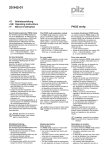
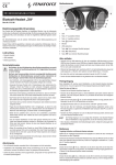
PROFIBUS-DP-Schnittstelle
Interface PROFIBUS-DP
1:
2:
3:
4:
5:
6:
7:
8:
9:
D
4
E
4
GB
4I
4
PROFIBUS-DP interface
Interfaccia PROFIBUS-DP
n.c
n.c.
B (RxD/TxD-P)
CNTR-P
DGND
VP
n.c.
A (RxD/TxD-N)
n.c.
Terminierung PROFIBUS-DP:
Um Leitungsreflexionen zu minimieren und einen definierten Ruhepegel
auf der Übertragungsleitung zu
garantieren, muss der PROFIBUS an
beiden Enden abgeschlossen
werden.
Terminación del PROFIBUS-DP:
Con objeto de minimizar reflexiones
en las líneas y garantizar un nivel de
reposo definido en la línea de
transmisión, se debe terminar el
PROFIBUS en ambos extremos con
resistencias.
6
GB
4
I
4
1
PROFIBUS-DP termination:
To minimise cable reflection and to
guarantee a defined rest signal on
the transmission line, the PROFIBUS
must be terminated at both ends.
Terminazione PROFIBUS-DP:
Per ridurre al minimo i riflessi di
conduzione e garantire una soglia di
riposo definita sulla linea di
trasmissione, il PROFIBUS deve
essere terminato su entrambe le
estremità.
PROFIBUS-DP
Slave 1
Interface PROFIBUS DP
PROFIBUS-DP-poort
n.c. = nicht belegt
n.c. = not connected
n.c. = non affecté
n.c. = sin asignar
n.c. = non occupato
n.c. = niet gebruikt
5
9
F
4NL
4
F
4
NL
4
Terminaison du bus
PROFI-BUS-DP:
Pour minimiser les réflexions le long
des conducteurs et pour garantir un
niveau de repos défini sur la liaison
de transmission, le bus PROFIBUS
doit être terminé à ses deux extrémités.
Afsluitweerstand PROFIBUS-DP:
Om kabelreflecties te minimaliseren
en een gedefinieerd rustniveau op de
overdrachtskabel te garanderen,
moet de PROFIBUS aan beide
uiteinden worden afgesloten.
PROFIBUS-DP
Slave n
PROFIBUS-DP
Slave 3
PROFIBUS-DP
X1
PROFIBUS-DP
Master
PNOZ mc3p PROFIBUS
ADDRESS
x10
x1
PNOZ mc3p
FAULT
OFFLINE
ONLINE
PROFIBUS-DP
Slave 2
4D
Abmessungen in mm (")
4GB Dimensions in mm (")
4F
4E
Dimensiones en mm (")
4I
4NL Afmetingen in mm (")
119 (4.69")
Dimensioni in mm (")
94 (3.70")
22,5
(0.88")
Dimensions en mm (")
4D
Anschlussbelegung
4GB Connector pin assignment
4F
4E
Asignación de conexiones
4I
4NL Klembezetting
Schema delle connessioni
Affectation des raccords
PROFIBUS-DP
X1
ADDRESS
x10
x1
ONLINE
A Pilz Ges.m.b.H., ✆ 01 7986263-0, Fax: 01 7986264, E-Mail: [email protected] AUS Pilz Australia Industrial Automation LP., ✆ 03 95446300, Fax: 03
95446311, E-Mail: [email protected]
B L Pilz Belgium, ✆ 09 3217570, Fax: 09 3217571, E-Mail: [email protected] BR Pilz do Brasil Sistemas Eletrônicos
Industriais Ltda., ✆ 11 4337-1241, Fax: 11 4337-1242, E-Mail: [email protected]
CH Pilz lndustrieelektronik GmbH, ✆ 062 88979-30, Fax: 062 88979-40,
E-Mail: [email protected]
DK Pilz Skandinavien K/S, ✆ 74436332, Fax: 74436342, E-Mail: [email protected] E Pilz lndustrieelektronik S.L., ✆ 938497433, Fax:
938497544, E-Mail: [email protected]
F Pilz France Electronic, ✆ 03 88104000, Fax: 03 88108000, E-Mail: [email protected] FIN Pilz Skandinavien K/S,
✆ 09 27093700, Fax: 09 27093709, E-Mail: [email protected] GB Pilz Automation Technology, ✆ 01536 460766, Fax: 01536 460866, E-Mail: [email protected]
I Pilz ltalia Srl, ✆ 031 789511, Fax: 031 789555, E-Mail: [email protected] IRL Pilz Ireland Industrial Automation, ✆ 021 4346535, Fax: 021 4804994, E-Mail:
[email protected]
J Pilz Japan Co., Ltd., ✆ 045 471-2281, Fax: 045 471-2283, E-Mail: [email protected] MEX Pilz de Mexico, S. de R.L. de C.V., ✆ 55 5572 1300,
Fax: 55 5572 4194, E-Mail: [email protected]
NL Pilz Nederland, ✆ 0347 320477, Fax: 0347 320485, E-Mail: [email protected] NZ Pilz New Zealand, ✆ 096345350, Fax: 09-6345350, E-Mail: [email protected]
P Pilz Industrieelektronik S.L., ✆ 229407594, Fax: 229407595, E-Mail: [email protected] PRC Pilz
China Representative Office, ✆ 021 62493031, Fax: 021 62493036, E-Mail: [email protected]
ROK Pilz Korea Office, ✆ 031 8159541, Fax: 031 8159542,
E-Mail: [email protected]
SE Pilz Skandinavien K/S, ✆ 0300 13990, Fax: 0300 30740, E-Mail: [email protected] TR Pilz Elektronik Güvenlik Ürünleri ve
Hizmetleri Tic. Ltd. Şti., ✆ 0224 2360180, Fax: 0224 2360184, E-Mail: [email protected]
USA Pilz Automation Safety L.P., ✆ 734 354-0272, Fax: 734 354-3355,
E-Mail: [email protected]
www www.pilz.com
D Pilz GmbH & Co. KG, Sichere Automation, Felix-Wankel-Straße 2, 73760 Ostfildern, Deutschland, ✆ +49 711 3409-0, Fax: +49 711 3409-133,
E-Mail: [email protected]
21 010-02-03/04 Printed in Germany
PNOZ mc3p
FAULT
OFFLINE