1
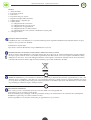
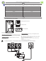
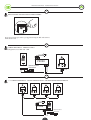
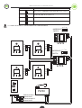
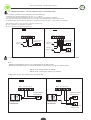
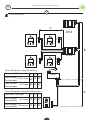
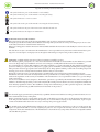
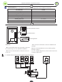
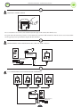
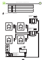
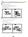
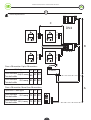
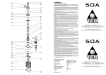
LIBRETTO ISTRUZIONI - INSTRUCTION MANUAL
Legenda dei simboli presenti nel manuale:
Questo simbolo evidenzia le parti del manuale da leggere con attenzione
Questo simbolo evidenzia le parti del manuale riguardante la sicurezza
Questo simbolo indica di prestare cautela
Questo simbolo evidenzia la parte del manuale riguardante il cablaggio elettrico
Questo simbolo indica la parte del manuale istruzione dedicato all’utente
Questo simbolo indica il capitolo riguardante la manutenzione
PREMESSA AL MANUALE ISTRUZIONI: le presenti istruzioni riguardano esclusivamente l’installazione elettrica e l’utilizzo
dei posti esterni PV1I e PV2I.
Nel corso delle operazioni di assemblaggio e montaggio e collaudo dell’impianto videocitofonico si possono verificare situazioni di pericolo se non si osservano le avvertenze di sicurezza contenute nelle istruzioni. Prima di procedere leggere
attentamente il presente manuale istruzioni. Rendere disponibili le istruzioni presso l’impianto per ogni necessità di utilizzo
e manutenzione.
I dati riportati sono da ritenersi puramente indicativi. Il costruttore declina ogni responsabilità per le possibili inesattezze
contenute nel presente manuale derivanti da errori di stampa o di trascrizione. L’ azienda si riserva il diritto di apportare modifiche atte a migliorare il prodotto senza preavviso.
AVVERTENZE : leggere attentamente le istruzioni prima di iniziare l’installazione del prodotto.
I materiali dell’imballaggio (plastica, polistirolo, ecc.) non vanno dispersi nell’ambiente e non devono essere lasciati alla portata dei bambini in quanto potenziali fonti di pericolo. La non corretta installazione può provocare gravi pericoli, seguire
attentamente tutte le istruzioni per l’installazione. Si raccomanda di lavorare nel pieno rispetto delle norme di sicurezza; di
operare in ambiente sufficientemente illuminato e idoneo per la salute; di indossare indumenti di protezione a norma di legge
(scarpe antinfortunistiche, occhiali di protezione, guanti ed elmetto) evitando di indossare articoli di abbigliamento che possano impigliarsi. Adottare misure di protezione adeguate al rischio di ferita dovuto a schegge acuminate e ai possibili rischi di
schiacciamento, urto e cesoiamento. si raccomanda di osservare rigorosamente le norme nazionali valide per la sicurezza nei
cantieri (in italia d. lgs. 528/99 coordinato con d. lgs. 494/96 “attuazione della direttiva 92/57/ cee concernente le prescrizioni
minime di sicurezza e di salute da adottare nei cantieri temporanei o mobili”). Delimitare il cantiere per impedire il transito a
persone non autorizzate e non lasciare incustodita la zona di lavoro. Installazione, collegamenti elettrici e regolazioni devono
essere effettuati nell’osservanza della buona tecnica e in ottemperanza alle norme vigenti nel paese di installazione. Il costruttore non è responsabile dell’inosservanza della buona tecnica nella costruzione. Un’ errata installazione può essere fonte di pericolo. Eseguire gli interventi come specificato dal costruttore. Prima di iniziare l’installazione, verificare l’integrità del prodotto
e verificare che la struttura esistente abbia i necessari requisiti di robustezza e stabilità e che risponda alle normative di settore
vigenti. L’installazione, il collaudo e la messa in funzione, così come le verifiche periodiche e gli interventi di manutenzione,
possono essere eseguiti soltanto da tecnici specializzati e formati sul prodotto.
L’impianto di alimentazione elettrica deve essere eseguito da un elettricista esperto e abilitato secondo i criteri nazionali, nel
rispetto delle norme nazionali di sicurezza degli impianti (in italia legge 46/90). Prima di collegare l’alimentazione elettrica
accertarsi che i dati di targa siano rispondenti a quelli della rete di distribuzione elettrica. Le misure di protezione sul primario
vengono adottate in cantiere/in opera. Prima di procedere a qualsiasi intervento di manutenzione, riparazione o sostituzione
sia meccaniche che elettriche è necessario interrompere l’alimentazione elettrica di rete.
L’installatore deve fornire tutte le informazioni relative al funzionamento e consegnare le istruzioni d’uso all’utilizzatore
dell’impianto. Per eventuali riparazioni o sostituzioni dovranno essere utilizzati esclusivamente ricambi originali. Non si riconosce la garanzia in caso di utilizzo combinato con componenti di altra marca. Il costruttore declina ogni responsabilità
qualora vengano installati componenti incompatibili ai fini della sicurezza e del buon funzionamento.
2
LIBRETTO ISTRUZIONI - INSTRUCTION MANUAL
INDICE:
1- Limiti di utilizzo
2- Descrizione generale
3- Dati tecnici
4- Descrizione del posto esterno
5- Regolazione anglolo della telecamera
6- Schema elettrico - Impianto tipo
7- Schemi elettrici
7.1- Collegamento fino a 4 monitor
7.2- Collegamento fino a 4 posti esterni
7.3- Collegamento di 2 appartamenti
7.4- Collegamento fino a 2 elettroserrature
7.5- Collegamento fino a due serrature controllate da contatto pulito
8- Cablaggio richiesto
REGOLE D’INSTALLAZIONE
L’installazione deve essere effettuata con ’osservanza delle disposizioni regolanti l’installazione del materiale elettrico in vigore
nel paese dove i prodotti sono installati.
Dichiarazione di conformità
Il prodotto è conforme alla direttiva europea 2004/108/CE e successive.
INFORMAZIONE AGLI UTENTI AI SENSI DELLA DIRETTIVA 2002/96 (RAEE)
Al fine di evitare danni all’ambiente e alla salute umana oltre che di incorrere in sanzioni amministrative, l’apparecchiatura
che riporta questo simbolo dovrà essere smaltita separatamente dai rifiuti urbani ovvero riconsegnata al distributore all’atto
dell’acquisto di una nuova. La raccolta dell’apparecchiatura contrassegnata con il simbolo del bidone barrato dovrà avvenire in
conformità alle istruzioni emanate dagli enti territorialmente preposti allo smaltimento dei rifiuti.
1
LIMITI DI UTILIZZO: I posti esterni PV1I e PV2I sono progettati per impianti videocitofonici rispettivamente per una o due
chiamate (mono o bifamiliari). Ogni altro uso è da considerarsi improprio e quindi pericoloso. È vietato utilizzare il prodotto
per scopi diversi da quelli previsti o impropri. È vietato manomettere o modificare il prodotto. ON Automation S.r.l. non assume
responsabilità per il mancato rispetto di tali prescrizioni.
2
DESCRIZIONE GENERALE
Posto esterno per una o due chiamate da incasso in acciaio INOX con tecnologia BUS 2K.
Videocamera a colori con angolo visuale di 105°
Facile da installare grazie al cablaggio a 2 fili non polarizzati, ideale per le ristrutturazioni e la sostituzione di vecchi impianti.
Installazione a parete del posto esterno tramite la cornice;
Sistema espandibile con un massimo di 4 monitor per appartamento e 4 posti esterni;
3
LIBRETTO ISTRUZIONI - INSTRUCTION MANUAL
3
DATI TECNICI:
prima installare il prodotto, verificare che i limiti di temperatura indicati siano adeguati all’ambiente di installazione.
DESCRIZIONE
VALORE
Alimentazione Posto esterno
24VDC
Consumo in Standby
60mA
Consumo di funzionamento
200mA
Camera
a colori
Uscita elettroserratura
12VDC 250mA
Range temperature di esercizio
- 0 ÷ +45 °C
Grado di protezione
IP56
Dimensioni (lxhxp)
130x270x38mm
4
ON
1 2
DESCRIZIONE DEL POSTO ESTERNO
DIP codice postazione esterna
1 2
ON
TR+ TR-
1 2 3
DIP elettroserratura
TR+ TR-
1 2 3
S1+
BUS PL
S2+S-
BUS collegamento
LEGENDA:
- BUS di collegamento: Morsetto per il collegamento della
linea BUS 2K e serrature.
- DIP codice postazione esterna: Si programma il codice del
posto esterno per un massimo di 4 posti esterni per impianto.
BUS: collegamento della linea BUS 2K, due fili senza polarità.
PL: Ingresso indipendente, tensione (+)
- DIP Elettroserratura: Si seleziona il numero di serrature
S1+ S2+: Uscita tensione serratura (+) per controllo di due
(vedi paragrafo 7.4)
serrature.
S-: Uscita tensione serratura (-)
7.1- SCHEMA ELETTRICO - COLLEGAMENTO FINO A 4 POSTI ESTERNI PER APPARTAMENTO
BUS
PL S1+ S2+ S-
BUS
PL S1+ S2+ S-
BUS
PL S1+ S2+ S-
ON
1
IMPEDENCE
SWITCH
BUS
PL S1+ S2+ S-
A B C D
DV4
PSV30
4
LIBRETTO ISTRUZIONI - INSTRUCTION MANUAL
5
REGOLAZIONE ANGOLO DELLA VIDEOCAMERA
Usare un cacciavite per svitare e poi aggiustare l’angolo della videocamera.
Infine fisare la vite
6
SCHEMA ELETTRICO - IMPIANTO TIPO
Collegamento base ONE -TO- ONE
PSV30
BUS
PL S1+ S2+ S-
Elettroserratura
Elettrolock
L1-L2
7
7.2- SCHEMA ELETTRICO - COLLEGAMENTO FINO A 4 MONITOR PER APPARTAMENTO
PSV30
BUS
5
PL S1+ S2+ S-
Elettroserratura
Elettrolock
LIBRETTO ISTRUZIONI - INSTRUCTION MANUAL
DIP POSTO ESTERNO
ON
1
2
ON
1
ID 01 (ON_OFF). Posto esterno n°3
2
ON
1
ID 10 (ON_OFF). Posto esterno n°2
2
ON
1
DESCRIZIONE
Impostazione di DEFAULT, ID 00 (OFF-OFF). Posto esterno n°1
ID 11 (ON_ON). Posto esterno n°4
2
7.3- SCHEMA ELETTRICO - COLLEGAMENTO DI 2 APPARTAMENTI
A B C D
ON
1
IMPEDENCE
SWITCH
L1
L2
S+
S-
L1
L2
S+
S-
DV4
A B C D
DV4
L1
L2
S+
S-
L1
L2
S+
S-
PSV30
BUS
PL S1+ S2+ S-
Elettroserratura 1
Electro-lock 1
Elettroserratura 2
Electro-lock 2
6
ON
1
IMPEDENCE
SWITCH
LIBRETTO ISTRUZIONI - INSTRUCTION MANUAL
7.4 SCHEMA ELETTRICO - COLLEGAMENTO FINO A DUE SERRATURE
La serratura è controllata da una alimentazione interna alla targa.
- Utilizzare una serratura elettrica tipo Power -on- a - unlock.
- La serratura della porta è limitata a 12V e la corrente deve essere inferiore a 250mA.
- Il tempo di funzionamento della serratura si può impostare tramite le impostazioni del monitor.
- I monitor hanno le impostazioni di fabbrica, quindi il parametro di sblocco è impostato su 0 (default).
Collegamento di una o due serruature (dip in possizione 2-3).
PL - S1+: Apertura con pulsante serratura 1
PL - S2+: Apertura con pulsante serratura 2
1 23
BUS
1 23
PL S1+S2+ S-
BUS
Elettroserratura 1
Electro-lock 1
Pulsante 1
Button 1
PL S1+S2+ S-
Elettroserratura 1
Electro-lock 1
Pulsante 1
Button 1
Pulsante 2
Button 2
Elettroserratura 2
Electro-lock 2
7.5 SCHEMA ELETTRICO - COLLEGAMENTO DI UNA SERRATURA CONTROLLATA DA CONTATTO PULITO
Nota:
- Utilizzare un alimentatore esterno con caratteristiche in base alla serratura.
- Impostare la modalità di sblocco serratura del monitor (unlock mode) per i tipi di serratura diversi:
Unlock mode=0 (impostazione di default)
Unlock mode=1 interruzione tensione per serrature
Collegamento di una o due serrature (dip senza ponticello)
1 23
PL S1+S2+ S-
Elettroserratura 1
Electro-lock 1
12VAC
BUS
230VAC
12VAC
230VAC
BUS
1 23
PL S1+S2+ S-
Elettroserratura 1
Electro-lock 1
Trasformatore
Transformer
Trasformatore
Transformer
Elettroserratura 2
Electro-lock 2
7
LIBRETTO ISTRUZIONI - INSTRUCTION MANUAL
8
A B C D
CABLAGGIO RICHIESTO
C
DV4
L1
L2
S+
S-
A B C D
L1
L2
S+
S-
B
DV4
L1
L2
S+
S-
L1
L2
S+
S-
Fino a 20 monitor- Up to 20 monitors
Tipo cavo- Cable type
A
B
C
PSV30
Cavo twistato
2X0,75 mmq 60 60 30
Twisted cable
Cavo twistato
Twisted cable
2X1 mmq 80 80 40
Fino a 20 monitor- More than 20 monitors
Tipo cavo- Cable type
A B C
2X1 mmq 70 30 20
PL S1+ S2+ S-
Cavo twistato
Twisted cable
A
BUS
Cavo twistato
2X1,5 mmq 70 50 30
Twisted cable
8
LIBRETTO ISTRUZIONI - INSTRUCTION MANUAL
Legenda dei simboli presenti nel manuale:
This symbol indicates parts of the manual to read carefully
This symbol indicates parts of the manual concerning the safety
This symbol indicates to exercise caution
This symbol shows the part of the manual concerning the electrical wiring
This symbol indicates the part of the instruction manual dedicated user
This symbol indicates the chapter on maintenance
INTRODUCTION TO THE MANUAL:
These instructions apply only to the electrical installation and use of door stations PV1I and PV2I.
During the operations of assembly and installation and testing of the system video door may occur danger if you do not observe the safety instructions contained in the instructions.
Before proceeding please read this instruction manual. Make available the instructions at the facility for each need to use and
maintain.
The data shown are just as an indication. The manufacturer is not responsible for any inaccuracies in this manual due to printing errors or transcription. Company reserves the right to make changes to improve the product without notice.
WARNING: carefully read the instructions before beginning to install the product.
The materials (plastic, polystyrene, etc.) must not be abandoned and should not be left within reach of children as potential
sources of danger. Improper installation can cause serious dangers, carefully follow all instructions for installation.
It is recommended to work in full compliance with safety standards; to operate adequately lit and suitable for health; wear
protective clothing as required by law (safety shoes, goggles, gloves and helmet) avoid wearing clothing that could get caught.
Take protective measures appropriate to the risk of injury due to sharp splinters and the possible risks of crushing, impact and
shearing. please observe strictly national standards valid for safety in construction.
Reduce the construction site to prevent the transit to unauthorized persons and not leave unattended the work area.
Installation, electrical connections and adjustments must be performed in accordance with good technique and in accordance
with current regulations in the country of installation. The manufacturer is not responsible for failure to use good technique
in the construction.
An ‘incorrect installation can be dangerous. Perform the operations as specified by the manufacturer. Before starting the installation, check the integrity of the product and verify that the existing structure has the necessary strength and stability and
meets industry regulations in force. The installation, testing and commissioning, as well as periodic inspections and maintenance can be performed only by skilled technicians and trained on the product.
The electrical supply system must be performed by a qualified electrician and enabled according to national criteria, in accordance with national security of the plants.
Before connecting the power supply, make sure the data on the label correspond to those of the electricity distribution network. The protective measures are taken on the primary site / at work. Before carrying out any maintenance, repair or replacement of mechanical and electrical is necessary to interrupt the power supply network.
The installer must supply all information relating to the operation and deliver instructions to the user of the system. For
repairs or replacements will be used only original spare parts. Do not recognize the warranty if used in combination with
components from other manufacturers. The manufacturer is not liable for any components which are incompatible with the
safe and efficient operation.
9
LIBRETTO ISTRUZIONI - INSTRUCTION MANUAL
INDEX:
1- Use Limitations
2- Overview
3- Technical
4- Description of the Door station
5- Adjustment camera angle
6- System wiring and connections
7- Wiring diagrams
7.1- Connection of up to 4 monitors
7.2- Connection up to 4 outdoor
7.3- Connection of 2 apartments
7.4- Electric lock connection
7.5- Connect up to two locks controlled with dry contact
8- Cables Requirements
REGULATIONS OF INSTALLATION
The installation must be done with ‘according to rules for the installation of electrical systems in the country where the products
are installed.
Statement of compliance
The product complies with the European Directive 2004/108 / EC and following.
INFORMATION FOR USERS UNDER DIRECTIVE 2002/96 (WEEE)
In order to avoid damage to the environment and human health as well as any administrative sanctions, the equipment marked
with this symbol must be disposed of separately from the municipal waste or returned to the dealer on purchase of a new one.
The collection of the equipment marked with the symbol of crossed bin must be in accordance with the instructions issued by
the bodies of local waste disposal department.
1
LIMITS OF USE: The outer seats PV1I PV2I and are designed for video systems respectively for one or two calls. Any other use is
considered improper and dangerous. You may not use the product for purposes other than those intended or improper. You may
not alter or modify the product. ON Automation S.r.l. does not assume responsibility for the failure to meet those requirements.
2
GENERAL DESCRIPTION
Outdoor station for one or two calls built-in stainless steel with BUS technology 2K.
Color camera with a viewing angle of 105 °
Easy to install thanks to the wiring 2-wire non-polarized, ideal for renovations and the replacement of old systems.
Wall installation of the external unit through the frame;
Expandable system with up to 4 monitors for apartment and 4 door stations;
10
LIBRETTO ISTRUZIONI - INSTRUCTION MANUAL
3
SPECIFICATIONS:
First install the product, verify that the temperature limits are appropriate to the installation environment.
DESCRIPTION
VALUE
Power Supply
24VDC
Consumption Standby
60mA
Consumption Working status
200mA
Camera
color
Lock power supply
12VDC 250mA
Working temperature
- 0 ÷ +45 °C
Protection level
IP56
Dimension (lxhxp)
130x270x38mm
4
ON
1 2
DESCRIPTION OF THE DOOR STATION
DIP codice postazione esterna
1 2
ON
TR+ TR-
1 2 3
DIP elettroserratura
TR+ TR-
1 2 3
S1+
BUS PL
S2+S-
BUS collegamento
LEGEND:
- BUS connection: Terminal for connection of BUS line 2K
and locks.
- DIP code external location: You program the code for the
door station for up to 4 door stations for installation.
- DIP Lock: You select the number of electronic Lock (see
section 7.4)
BUS: line connection BUS 2K, two wires without polarity.
PL: Input, voltage (+)
S1 + S2 +: Output voltage lock (+) for the control of two locks.
S: Output voltage lock (-)
7.1- CONNECTING UP TO 4 DOOR STATIONS FOR APARTMENT
BUS
PL S1+ S2+ S-
BUS
PL S1+ S2+ S-
BUS
PL S1+ S2+ S-
ON
1
IMPEDENCE
SWITCH
BUS
PL S1+ S2+ S-
A B C D
PSV30
DV4
11
LIBRETTO ISTRUZIONI - INSTRUCTION MANUAL
5
ADJUSTING CAMERA ANGLE
Use a screwdriver to loosen the screw and then adjust the angle of the camera, then fix the screw.
In seguito fissare la viteioni nei pozzetti e i cavi di entrata nel contenitore della centrale di comando devono essere inseriti utilizzando appositi pressavi per mantenere il grado IP del contenitore.
6
SYSTEM WIRING AND CONNECTIONS: Basic ONE -TO- ONE connection
PSV30
BUS
PL S1+ S2+ S-
Elettroserratura
Elettrolock
L1-L2
7
7.2- CONNECTING UP TO 4 MONITOR FOR APARTMENT
PSV30
BUS
12
PL S1+ S2+ S-
Elettroserratura
Elettrolock
LIBRETTO ISTRUZIONI - INSTRUCTION MANUAL
DOOR STATION DIP
1
2
ID 10 (ON_OFF). Set to the second Door Station.
ON
1
2
ID 01 (ON_OFF). Set to the third Door Station
ON
1
2
ID 11 (ON_ON). Set to the fourth Door Staton.
ON
1
DESCRIPTION
DEFAULT setting, ID 00 (OFF-OFF). Set to the first Door Station
ON
2
7.3- CONNECTION OF 2 APARTMENTS
A B C D
ON
1
IMPEDENCE
SWITCH
L1
L2
S+
S-
L1
L2
S+
S-
DV4
A B C D
DV4
L1
L2
S+
S-
L1
L2
S+
S-
PSV30
BUS
PL S1+ S2+ S-
Elettroserratura 1
Electro-lock 1
Elettroserratura 2
Electro-lock 2
13
ON
1
IMPEDENCE
SWITCH
LIBRETTO ISTRUZIONI - INSTRUCTION MANUAL
7.4 - ELECTRIC LOCK CONNECTION
The lock is controlled by an internal power supply.
- Use an electric lock type Power -on- to - unlock.
- The door lock is limited to 12V and the current must be less than 250mA.
- The operating time of the lock can be set through the monitor settings.
- Monitors have the factory settings, then the unlock parameter is set to 0 (default).
Connecting one or two serruature (dip in possizione 2-3).
PL - S1 +: Opening with button lock 1
PL - S2 +: Opening with button lock 2
1 23
BUS
1 23
PL S1+S2+ S-
BUS
Elettroserratura 1
Electro-lock 1
Pulsante 1
Button 1
PL S1+S2+ S-
Elettroserratura 1
Electro-lock 1
Pulsante 1
Button 1
Pulsante 2
Button 2
Elettroserratura 2
Electro-lock 2
7.5 - CONNECTION OF A LOCK CONTROLLED WITH DRY CONTACT
Note:
- Use an external power supply with features according to the lock.
- Setup the unlock mode of monitor for different lock types:
Unlock mode = 0 (default)
Unlock mode = 1 for voltage interruption lock
Connecting one or two locks (dip without jumper)
1 23
Trasformatore
Transformer
PL S1+S2+ S-
BUS
12VAC
Elettroserratura 1
Electro-lock 1
230VAC
12VAC
230VAC
BUS
1 23
PL S1+S2+ S-
Elettroserratura 1
Electro-lock 1
Trasformatore
Transformer
Elettroserratura 2
Electro-lock 2
14
LIBRETTO ISTRUZIONI - INSTRUCTION MANUAL
8
A B C D
CABLES REQUIREMENTS
C
DV4
L1
L2
S+
S-
A B C D
L1
L2
S+
S-
B
DV4
L1
L2
S+
S-
L1
L2
S+
S-
Fino a 20 monitor- Up to 20 monitors
Tipo cavo- Cable type
A
B
C
PSV30
Cavo twistato
2X0,75 mmq 60 60 30
Twisted cable
Cavo twistato
Twisted cable
2X1 mmq 80 80 40
Fino a 20 monitor- More than 20 monitors
Tipo cavo- Cable type
B
A
C
2X1 mmq 70 30 20
PL S1+ S2+ S-
Cavo twistato
Twisted cable
A
BUS
Cavo twistato
2X1,5 mmq 70 50 30
Twisted cable
15