1
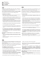
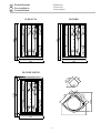
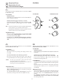
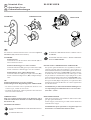
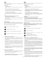
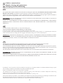
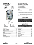
GB
DE
IT
GB
DE
Manuale di preinstallazione - installazione - uso
Pre-installation - installation - operating manual
Anweisungen für Vorinstallation - Installation - Gebrauch
Box doccia modelli
Shower booths models
Duschkabinen Modelle
D-DOCCIA
ID-IDRO
DI-NEBULIZER
NIAGARA A90
IT
IT
GB
DE
Premessa
Assumption
Vorwort
GB
IT
Il Box Doccia NIAGARA dopo essere stato sottoposto a
collaudo in azienda viene smontato per facilitarne il trasporto
e l’introduzione nel locale di destinazione.
Si raccomanda di ispezionare con cura i componenti del Box
Doccia prima di procedere all’installazione. Danni reclamati
ad installazione avvenuta sono esclusi dalla garanzia.
After having been inspected by the manufacturers, the
NIAGARA Shower Booth is disassembled for easier transportation and entrance into the premises of destination.
We suggest you carefully check all the Shower Booth parts before starting to install it. Any damages claimed after the installation has been effected are excluded from the guarantee.
NORME DI SICUREZZA
- I Box Doccia sono costruiti nel pieno rispetto delle direttive
CEE e delle Leggi nazionali vigenti in materia.
SAFETY RULES
- The Shower Booths are manufactured in full accordance with
the EEC directives and with the national Laws in force in
this field.
- L’INSTALLAZIONE DEVE ESSERE ESEGUITA DA
PERSONALE IN POSSESSO DEI REQUISITI TECNICOPROFESSIONALI CONFORMI ALLE LEGGI E NORME
NAZIONALI VIGENTI IN MATERIA.
- IL MONTAGGIO DEL BOX DOCCIA E LA SUA
INSTALLAZIONE DOVRANNO ESSERE ESEGUITI
OSSERVANDO LE ISTRUZIONI DI SEGUITO FORNITE.
- THE INSTALLATION MUST BE EFFECTED BY PERSONNEL POSSESSING THE TECHNICAL AND PROFESSIONAL QUALIFICATIONS REQUIRED BY THE NATIONAL REGULATIONS AND SPECIFICATIONS IN
FORCE IN THIS FIELD.
- THE ASSEMBLY AND INSTALLATION OF THE SHOWER
BOOTH MUST BE EFFECTED IN COMPLIANCE WITH
THE INSTRUCTIONS GIVEN HEREAFTER.
- L’installatore dovrà verificare, sotto la propria responsabilità,
la corretta predisposizione degli impianti.
- The installer must check, under his own responsibility, that
the waterworks are correctly set up for the installation.
- In caso di malfunzionamento del box doccia l’UTENTE deve
contattare il CENTRO DI ASSISTENZA TECNICA più
vicino.
- If the shower booth should not work properly, the USER must
contact the nearest AFTER SALES SERVICE.
- E’ vietato toccare, maneggiare o azionare apparecchi
elettrici utilizzando il box doccia. Il non rispetto di questa
norma di sicurezza può essere causa di grave pericolo
per l’UTENTE.
- It is strictly prohibited to touch, handle or switch on electric equipment while using the shower booth. It would be
very dangerous for the USER if he should not abide by this
safety rule.
IL PRODUTTORE DECLINA OGNI RESPONSABILITÀ:
- Qualora non vengano rispettate le disposizioni di Legge e
norme nazionali vigenti in materia di sicurezza per i locali
da bagno.
- Qualora non vengano rispettate le istruzioni fornite nel
presente manuale.
THE MANUFACTURER DECLINES ANY LIABILITY :
- If the national regulations and specifications in force in the
field of bathroom safety are not complied with.
- If the instructions supplied in this manual are not respected.
DE
Um den Transport bis zum Aufstellungsort zu erleichtern, wird
die Duschkabine NIAGARA, nachdem sie im Werk getestet
wurde, demontiert.
Prüfen Sie die Bestandteile Ihrer Duschkabine unbedingt vor
der Installation. Schäden, die erst nach der Installation gemeldet
werden, sind von der Garantie ausgeschlossen.
SICHERHEITSANWEISUNGEN
- Unsere Duschkabinen werden gemäß den EU-Richtlinien und
der national gültigen Gesetzen gebaut.
- DIE INSTALLATION MUSS DURCH - GEMÄSS DER
GÜLTIGEN GESETZEN UND NORMEN - TECHNISCH
QUALIFIZIERTES PERSONAL ERFOLGEN.
- DIE MONTAGE DER DUSCHKABINE UND DEREN
INSTALLATION MÜSSEN UNTER BEACHTUNG DER
ANSTEHENDEN ANWEISUNGEN ERFOLGEN.
Anlage unter eigener Verantwortung prüfen.
- Bei Betriebsstörungen der Duschkabine muß sich der
BENUTZER an die nächstliegende KUNDENDIENSTSTELLE wenden.
- Es ist untersagt, während der Anwendung der
Duschkabine elektrische Geräte anzufassen,
handzuhaben oder zu betätigen. Ein fehlendes Beachten
dieser Sicherheitsvorschrift kann für den BENUTZER
äußerst gefährlich sein.
DER HERSTELLER LEHNT JEGLICHE VERANTWORTUNG AB:
- wenn die einschlägig gültigen Sicherheitsvorschriften für
Badezimmer nicht beachtet werden.
- wenn die hier aufgelisteten Anweisungen nicht befolgt
werden.
- Der Installateur muß die einwandfreie Vorbereitung der
-2-
Dimensioni
Dimensions
Abmessungen
18
18
203
185
ID-IDRO
203
185
D-DOCCIA
131
131
12
46,5
,5
35
,5
35
15,5
DI-NEBULIZER
106,5
93
,5
93
76
,5
185
DE
218,5
GB
Preinstallazione
Pre-installation
Vorinstallation
131
18
IT
131
-3-
IT
GB
DE
Preinstallazione
Pre-installation
Vorinstallation
IT
Il Box doccia NIAGARA é disponibile nei modelli:
D-DOCCIA
Versione senza Tetto, con Pareti interne laterali.
Funzione doccia.
Funzionamento idraulico con miscelatore.
ID-IDRO
Versione completa di Tetto e Pareti interne laterali.
Funzione doccia, idromassaggio verticale-lombare e
cervicale.
Funzionamento idraulico con miscelatore e deviatore.
17
9
DI-NEBULIZER
Versione completa di Tetto e Pareti interne laterali.
Funzione doccia, Idromassaggio Verticale-Lombare e
Cervicale, Bagno Turco o Bagno Refrigerante con
vaporizzatori nebulizzanti.
Funzionamento idraulico con miscelatore e due deviatori.
10
F
V
130
PREDISPOSIZIONI ALLACCIAMENTO IDRAULICO
I tubi di alimentazione dell’acqua calda (C) e fredda (F) del
Box Doccia devono sporgere dal muro con attacchi da 1/2”.
Si consiglia di dotare i tubi di valvola a sfera (V) per agevolare
eventuali operazioni di manutenzione del box. In fase di
installazione si dovranno collegare le suddette uscite con il
gruppo miscelazione montato sul retro della colonna
utilizzando tubi flessibili in acciaio inossidabile da 1/2”.
C
12
76
SCARICO A PAVIMENTO
I Box Doccia vengono dotati di piletta di scarico con relativo
sifone. Lo scarico a pavimento, tenuto debito conto
dell’ingombro del sifone, va predisposto a circa 25-35 cm. dallo
scarico del piatto doccia.
5
-4-
÷3
SI CONSIGLIA L’INSTALLAZIONE DI UN FILTRO
DELL’ACQUA DI ALIMENTAZIONE DA 100 MICRON E
DI UN ANTICALCARE.
25
NOTA BENE: per il regolare funzionamento dell’impianto
devono essere garantiti:
- Portate e pressioni dell’acqua calda e fredda da 1,5 a 3,0 bar
- Alimentazione con acqua esente da impurità (sabbia, ruggine
ecc.).
IT
GB
DE
Preinstallazione
Pre-installation
Vorinstallation
DE
GB
The NIAGARA shower booth is available in:
Die Duschkabine NIAGARA ist in den Ausführungen:
D-DOCCIA
Version without ceiling, with internal side Panels.
Includes shower.
Hydraulic operation with mixer.
D-DOCCIA
Ausführung einschließlich inneren Seitenwänden.
Ohne Haube
Funktion Dusche.
Hydraulik Funktion mit Einhandmischer.
ID-IDRO
Version complete with ceiling and internal side Panels.
Includes shower, Vertical - Lumbar and Cervical watermassage.
Hydraulic operation with mixer and deviator.
DI-NEBULIZER
Version complete with ceiling and internal side Panels.
Includes shower, Vertical - Lumbar and Cervical watermassage, Turkish Bath and Cold Bath with vaporizing
nozzles.
Hydraulic operation with mixer and two deviator.
WATER PIPE CONECTIONS
The hot water pipes (C) and the cold water pipes(F) of the
Shower Booth must protrude from the wall with 1/2 “ connections. It is advisable to equip the pipes with ball valves (V) to
facilitate booth maintenance if necessary. During the installation phase, the pipe outlets must be connected to the cold/
hot water mixing unit situated at the back of the column, by
using 1/2 “ stainless steel flexible pipes.
FLOOR DRAIN
The shower booths are equipped with a floor drain and draintrap. The floor drain, keeping into account the size of the
drain-trap, must be located at about 25-35 cm. from the shower
tray drain.
NOTE : to ensure regular operation the following must be
guaranteed :
- Hot and cold water flow rate and pressure from 1,5 to 3,0
bars.
- Input of water without impurities (sand, rust,etc.).
WE RECOMMEND THE INSTALLATION OF A 100 MICRON
WATER FILTER AND A WATER SOFTENER.
ID-IDRO
Ausführung einschließlich Haube und inneren
Seitenwänden.
Funktion Dusche, vertikale Unterwassermassage,Unterwassermassage im Lenden- und Nackenbereich.
Hydraulik Funktion mit Einhandmischer und Umleiter.
DI-NEBULIZER
Ausführung einschließlich Haube und inneren
Seitenwänden.
Funktion Dusche, vertikale Unterwassermassage,Unterwassermassage im Lenden- und Nackenbereich, Türkisches
Bad und Erfrischungsbad mit Zerstäubern;
Hydraulik Funktion mit Einhandmischer und 2 Umleiter.
VORBEREITUNG WASSERANSCHLUSS
Die Warm- (C) und Kaltwasserleitungen (F) der Duschkabine
müssen aus der Wand hervorragen und mit 1/2”-Anschlüssen
ausgestattet sein.
Es ist empfehlenswert, die Leitungen mit Kugelventilen (V)
zu versehen, um eventuelle Instandhaltungsarbeiten an der
Duschkabine zu vereinfachen. Die oben angeführten Leitungen
müssen bei der Installation unter Anwendung von biegsamen
Edelstahlrohren zu 1/2” an die Mischeinheit hinter der Säule
angeschlossen werden.
ABFLUSS AM BODEN
Die Duschkabinen sind mit einer Abflußsäule einschließlich
Siphon ausgestattet. Der Abfluß am Boden muß unter
Beachtung der Sperrmaße des Siphons ca. 25-35 cm weit vom
Abfluß der Duschwanne vorbereitet werden.
ANMERKUNG: für einen einwandfreien Anlagenbetrieb
ist folgendes zu gewährleisten:
- Durchsatz und Druck des Warm- und Kaltwassers zwischen
1,5 und 3,0 bar
- Wasserversorgung mit sauberem Wasser (kein Sand, Rost,
usw.).
ES IST EMPFEHLENSWERT, AN DER VERSORGUNGSLEITUNG EINEN WASSERFILTER MIT 100 MICRON
UND
EINEN
ENTKALKUNGSFILTER
ZU
INSTALLIEREN.
-5-
IT
GB
DE
Distanze di sicurezza
Safety distances
Sicherheitsabstände
Preinstallazione
Pre-installation
Vorinstallation
Zona 1
Zona
a2
Zon
2
Zona 1
Zone 1
Bereich 1
Zona
3
3
Zona 2
Zone 2
Bereich 2
225 cm
a
Zon
60
240
60
cm
cm
Zona 3
Zone 3
Bereich 3
Zona 2
cm
240
cm
Zona 3
IT
PRECAUZIONE
Per evitare che residui solidi possano danneggiare la superficie del piatto doccia od ostruirne lo scarico, si consiglia di proteggere il
fondo del box con un foglio di cellophane e con del cartone.
NB:
Nell’installazione del box doccia é vietato l’uso di silicone acetico.
GB
PRECAUTIONS
To prevent solid particles from damaging the surface of the shower plate, or from obstructing the drain, we recommend you protect the
bottom of the booth with a sheet of cellophane and a piece of cardboard.
Note:
It is prohibited to use acetic silicone when installing the shower booth.
DE
VORSICHTSMASSNAHMEN
Um zu vermeiden, daß die Oberfläche der Duschwanne durch eventuelle Festkörper beschädigt wird oder daß diese den Abfluß
verstopfen, ist der Boden der Duschkabine mit Karton oder Plastikfolie abzudecken.
N.B.:
Bei der Installation der Duschkabine darf kein essigsaures Silikon verwendet werden.
-6-
IT
GB
DE
Istruzioni per l’installazione
Installation instructions
Installationsanweisungen
D-DOCCIA
ID-IDRO
DI-NEBULIZER
Fig. 1
IT
Posizionamento piatto
Posizionare il piatto doccia nell'angolo scelto e mettere in piano controllando l’appoggio dei piedini sul pavimento (eventualmente regolare l’altezza avvitandoli o svitandoli).
Controllare l'accostamento dei due fianchi al muro.
90°
GB
Fitting the shower tray
Place the shower tray in the corner chosen and level it by
checking that the feet are placed correctly on the floor (if
necessary, adjust their height by screwing or unscrewing them).
Check that the two panels are correctly positioned against the
wall.
1
2
DE
Positionierung der Duschwanne
Die Duschtasse ins gewünschte Eck stellen und nivellieren,
wobei darauf zu achten ist, dass die Stellfüsse am Boden
aufsitzen (die Höhe eventuell durch Ein- oder Ausschrauben
einstellen). Sicherstellen, dass die beiden Seitenteile gut an
der Wand stehen.
Fig. 1
Fig. 2
Montaggio piletta
Montare sul piatto doccia la piletta come da illustrazione
siliconando le parti necessarie.
Montare il tubo di scarico sulla piletta e predisporre per il collegamento allo scarico.
IT
1
GB
Fitting the drain
Fit the drain to the shower tray as shown in the picture and
apply silicone on the necessary parts.
Fit the drainpipe to the drain and prepare it for connection to
the floor drain.
DE
Montage der Abfluss-Säule
Die Abfluss-Säule laut Abbildung an der Duschtasse montieren
und an den nötigen Stellen mit Silikon abdichten.
Das Abflussrohr an der Abfluss-Säule montieren und für den
Anschluss an den Abfluss vorbereiten.
2
Fig. 2
-7-
IT
GB
DE
Istruzioni per l’installazione
Installation instructions
Installationsanweisungen
D-DOCCIA
ID-IDRO
DI-NEBULIZER
1
2
Fig. 3
Fig. 3
IT
Montaggio pareti su colonna
Prelevare la colonna e con punta Ø8 eseguire n°7+7 fori in corrispondenza con i fori del telaio.
Con n° 7+7 viti M6 complete di rondelle Ø6x12 e dadi montare senza bloccare le pareti, con alle estremità n°2 squadrette,
accoppiandole alla colonna.
Allineare internamente le pareti alla colonna e bloccare le viti.
GB
Fitting the shower panels onto the column
Take the column and, using an 8 mm diameter bit, drill 7 + 7 holes corresponding with the holes on the frame.
Using 7+7 M6 screws with 6x12 Ø washers, assemble the panels with 2 brackets on the ends by fitting them onto the column
without fixing them.
Align the shower panels to the column from the inside and tighten the screws.
DE
Montage der Wände an der Säule
Die Säule aus der Verpackung nehmen und 7+7 Bohrungen mit einer Spitze mit ∅ 8 übereinstimmend mit den Bohrungen im
Rahmen durchführen.
Die Wände mit Nr. 7+7 Schrauben M6 einschliesslich Unterlegscheiben ∅ 6x12 und Muttern mit den beiden Winkeln an den
Enden an der Säule montieren, ohne die Schrauben zu fest anzuziehen.
Die Wände innen an der Säule ausrichten und die Schrauben festziehen.
-8-
IT
GB
DE
Istruzioni per l’installazione
Installation instructions
Installationsanweisungen
D-DOCCIA
ID-IDRO
DI-NEBULIZER
40
0m
m
4
3
2
5
22
0m
m
1
Fig. 4
Fig. 4
IT
Montaggio assieme pareti / colonna su piatto
Posizionare l' assieme colonna pareti sul piatto doccia centrando il
raggio di curvatura della colonna con il raggio di curvatura del piatto
doccia.
Nella parte posteriore del box eseguire n°1+1 fori passanti Ø7 sulle
pareti e sul piatto doccia in corrispondenza dei fori delle squadrette.
Posizionare n°1+1 piastrina sui bordi delle pareti ponendo il centro
dell’asola a 220 mm dal foro della squadretta ed eseguire altri n°1+1
fori passanti Ø7.
Mettendole al centro dei fori, inserire n°2+2 rondelle in gomma
siliconica Ø4x16 tra il piatto doccia e le pareti.
Con n° 2+2 viti M6x60 complete di rondelle Ø6x12 e dadi fissare
l’assieme pareti/colonna sul piatto doccia.
N.B.: Eseguire le stesse forature anche nella parte alta delle due pareti ponendo i fori anteriori a circa 400 mm dai fori delle due
squadrette.
Fitting the shower panel/column assemnly to the shower
tray
Place the column/shower panel assembly onto the shower tray and
centre the radius of curvature of the column with the radius of
curvature of the shower tray.
Drill 1 + 1 Ø 7 mm through holes at the back of the shower booth on
the shower panels and on the shower tray in correspondence with the
bracket holes.
Place 1 + 1 plates on the edges of the shower panels by locating the
centre of the slot at 220 mm from the bracket hole and drill additional
1+1 Ø 7 mm through holes.
Place 2+2 Ø 4x16 mm washers in silicone rubber at the centre of the
holes between the shower tray and the shower panels and insert them.
By using 2+2 M6x60 screws with Ø 6x12 mm washers and nuts, fix
the shower panel/column assembly to the shower tray.
GB
N.B. Drill the same holes in the upper part of the shower panels,
locating the front holes at a distance of about 400 mm from the two
brackets.
DE
Montage der Einheit Wände/Säule an der Duschtasse
Die Einheit Wände/Säule auf die Duschtasse stellen wobei der Radius der Säule mit dem Radius der Duschtasse übereinstimmen muss.
Im hinteren Bereich der Duschkabine an den Wänden und an der Duschtasse 1+1 durchgehende Bohrungen mit ∅ 7 übereinstimmend mit den
Bohrungen der Winkel durchführen.
Die 1+1 Blechteile am Rand der Wände anordnen, wobei die Mitte der Öse 220 mm weit von der Bohrung des Winkels entfernt sein muss und
weitere 1+1 durchgehende Bohrungen mit ∅ 7 durchführen.
2+2 Unterlegscheiben aus Silikongummi mit ∅ 4x16 in der Mitte der Bohrungen zwischen der Duschtasse und den Wänden einsetzen.
Die Einheit Wände/Säule mit 2+2 Schrauben M6x60 einschliesslich Unterlegscheiben mit ∅ 6x12 und Muttern an der Duschtasse befestigen.
Anmerkung:
Die gleichen Bohrungen auch im oberen Bereich der beiden Wände durchführen, wobei die vorderen Bohrungen ca. 400 mm von den
Bohrungen der beiden Winkel entfernt sein müssen.
-9-
IT
GB
DE
Istruzioni per l’installazione
Installation instructions
Installationsanweisungen
D-DOCCIA
ID-IDRO
DI-NEBULIZER
2
Fig. 5
Assiemaggio telaio con vetri fissi
Montare la traversa inferiore e la traversa superiore inserendole sui rispettivi profili di un vetro fisso.
Inserire il secondo vetro fisso.
Fissare l’assieme telaio con vetri utilizzando n°2+2 viti
Ø3,9x32.
IT
4
Assembly of frame to fixed glass panel.
Assemble the lower and upper crosspiece by sliding them onto
the respective edges of 1 fixed glass panel.
Insert the second fixed glass panel.
Fix the frame assembly with glass panels using 2+2 Ø3,9x32
screws.
GB
Zusammenbau des Rahmens mit den fixen
Glasscheiben
Den unteren und oberen Querbalken in die diesbezüglichen
Profile einer der fixen Glasscheibe schieben.
Die zweite fixe Glasscheibe einschieben.
Den Rahmen mit den Glasscheiben mit Nr. 2+2 Schrauben Ø
3.9x32 fixieren.
3
DE
1
Fig. 5
Fig. 6
Montaggio assieme telaio con vetro
IT
Posizionare l' assieme telaio con vetro sul piatto doccia inserendolo nei profili compensatori fissati sulle pareti del box.
Centrare la posizione dell'assieme telaio nei profili
compensatori e sul piatto doccia.
GB
Fitting the frame and glass assembly
Place the frame and glass assembly onto the shower tray and
insert it into the compensating profiles fixed to the shower
panels.
Centre the position of the frame assembly with respect to the
compensating mouldings and to the shower tray.
DE
Montage der Einheit Rahmen mit Glasscheibe
Die Rahmeneinheit mit Glasscheibe auf die Duschtasse stellen
und dabei in die Ausgleichsprofile an den Duschwänden
einsetzen.
Die Einheit des Rahmens in den Ausgleichsprofilen und auf
den Duschtasse zentrieren.
Fig. 6
- 10 -
IT
GB
DE
Istruzioni per l’installazione
Installation instructions
Installationsanweisungen
D-DOCCIA
ID-IDRO
DI-NEBULIZER
Fig. 7
Montaggio componenti su porte vetro
Inserire le guarnizioni nelle sedi delle due traverse della porta.
Con n°8 viti Ø3,5x13 montare sulla porta senza bloccare, n°4
assieme carrello con rotelle.
Ripetere le stesse operazioni per la seconda porta.
IT
1
2
GB
Assembly of components on doors
Insert the gaskets in their housings on the two door crosspieces.
Using 8 Ø3,5x13 screws, assemble 4 roller elements with
wheels without locking them.
Repeat the same operation for the second door.
DE
Montage der Komponenten an der Tür
Die Dichtungen in den beiden Querbalken der Tür anordnen.
Die 4 Führungen mit Rollen mit Nr. 8 Schrauben Ø 3,5x13 an
der Tür befestigen, ohne die Schrauben festzuziehen.
Die gleichen Schritte für die zweite Tür vornehmen.
Fig. 7
4
Fig.8
Montaggio porte su assieme telaio
IT
Inserire le rotelline della porta prima nella guida del profilo
inferiore e poi, agendo sul perno di regolazione, nella guida
del profilo superiore.
Stringere bene le viti facendo in modo che le porte si chiudano
perfettamente.
2
GB
Fitting the door to the frame assembly
Fit the door wheels in the track of the lower edge first and
then in the track of the upper edge by pressing the adjusting
pin.
Tighten the screws securely, making sure that the doors shut
perfectly.
1
DE
Montage der Tür an der Rahmeneinheit
Die Rollen der Tür zuerst in der Schiene am unteren Profil und
dann durch Druck auf den Reglerzapfen in der Schiene am
oberen Profil einsetzen. Die Schrauben gut festziehen, damit
die Türen einwandfrei schließen.
3
Fig. 8
- 11 -
IT
GB
DE
Istruzioni per l’installazione
Installation instructions
Installationsanweisungen
ID-IDRO
DI-NEBULIZER
Fig. 9
Fig. 9
IT
Montaggio tetto
Prelevare e posizionare il tetto centrandolo sulle pareti e sul profilo superiore dell'assieme telaio con vetro.
Eseguire n° 2+2 fori Ø7 in corrispondenza dei fori superiori delle due pareti.
Fissare il tetto, con n° 4 viti M6x30 complete di rondelle Ø6x12 e dadi.
Inserire la guarnizione coprifuga sul bordo posteriore delle due pareti.
NB: Le alette delle guarnizioni coprifuga devono essere verso l’esterno del box doccia.
Fitting the ceiling
GB
Take the ceiling and place it central to the shower panels and to the upper edge of the frame and glass assembly.
Drill 2+2 x 7 cm holes in correspondence with the upper holes of the two shower panels.
Fix the ceiling using 4 x M6x30 screws with Ø 6x12 mm washers and nuts.
Insert the gap-covering gasket in the top edge of the two shower panels.
N.B. The tabs of the gap-covering gasket must point towards the outside of the shower booth.
DE
Montage der Haube
Die Haube aus der Verpackung nehmen und so anordnen, dass sie auf den Wänden und am oberen Profil der Einheit des
Rahmens mit Glasscheibe zentral sitzt.
Übereinstimmend mit den oberen Bohrungen der beiden Wände 2+2 Bohrungen mit ∅ 7 durchführen.
Die Haube mit 4 Schrauben M6x30 einschliesslich Unterlegscheiben mit ∅ 6x12 und Muttern befestigen.
Die Dichtung zur Fugenabdeckung am hinteren Rand der beiden Wände einsetzen.
Zur Beachtung: Die Dichtung zur Fugenabdeckung montieren Profile müssen gegen die Außenseite der Duschkabine
gerichtet sein.
- 12 -
IT
GB
DE
Istruzioni per l’installazione
Installation instructions
Installationsanweisungen
ID-IDRO
DI-NEBULIZER
1
2
20
0
3
4
Fig. 10
Fig. 10
Fissaggio box (consigliato)
IT
a) A 200 mm dal bordo esterno del tetto con punta Ø7 eseguire n°1+1 fori passanti tra tetto e parete.
Con n°1+1 vite M6x30 complete di rondelle Ø6x12 e dadi montare senza bloccare n°2 squadrette per il fissaggio del box al
muro.
b) Dopo aver posizionato correttamente il box nell’angolo scelto; in corrispondenza dei fori delle due squadrette di fissaggio
eseguire sul muro n°1+1 fori per tasselli Ø6.
Posizionare i tasselli e con viti Ø4,2x38 complete di rondelle fissare le squadrette sul muro.
Bloccare le squadrette sul box.
GB
Fixing the shower booth (recommended)
a) Using a Ø 7 bit, drill 1+1 holes through the ceiling and the shower panel at a distance of 200 mm from the external edge of
the ceiling.
Using 1+1 M6x30 screws with Ø6x18 mm washers and nuts, assemble 2 brackets for fixing the shower to the wall but do not
secure them.
b) After having placed the shower in its correct position, in correspondence with the holes of the two fixing brackets drill 1+1
holes for Ø 6 mm dowels in the wall.
Place the dowels in their correct position and using Ø 4.2 x 38 mm screws with washers fix the brackets to the wall.
Secure the brackets to the shower booth.
DE
Befestigung der Duschkabine (empfohlen)
a) Bei 200 mm Abstand vom äusseren Rand der Haube mit einer Bohrspitze mit ∅ 7 1+1 durchgehende Bohrungen zwischen der
Haube und der Wand durchführen.
Die 2 Winkel zur Befestigung der Duschkabine an der Wand mit 1+1 Schrauben M6x30 einschliesslich Unterlegscheiben ∅
6x18 und Muttern montieren, ohne die Schrauben festzuziehen.
b) Nachdem die Duschkabine korrekt aufgestellt wurde, an der Wand in Übereinstimmung mit den Bohrungen der beiden
Befestigungswinkeln 1+1 Löcher für Dübel mit ∅ 6 bohren.
Die Dübel einsetzen und die Winkel mit Schrauben mit ∅ 4.2x38 einschliesslich Unterlegscheiben an der Wand befestigen.
Die Winkel an der Duschkabine befestigen.
- 13 -
IT
GB
DE
Istruzioni per l’installazione
Installation instructions
Installationsanweisungen
D-DOCCIA
ID-IDRO
DI-NEBULIZER
Fig. 11
IT
Allacciamento allo scarico
Eseguire il collegamento dello scarico a pavimento.
GB
Connecting to the drain
Connect the floor drain.
DE
Anschluss an den Abfluss
Den Abfluss am Boden anschliessen.
Fig. 11
Fig. 12
IT
Alimentazione idraulica
Collegare il gruppo di miscelazione acqua calda (C) ed acqua
fredda (F), montato sul retro della colonna, alla rete idraulica
dell’abitazione utilizzando due tubi flessibili in acciaio inossidabile con attacchi da 1/2”.
Verificare che i collegamenti eseguiti non abbiamo perdite d’acqua.
Spostare il box nell’angolo previsto.
D-DOCCIA
F
C
GB
Water supply
Connect the hot (C) and cold (F) water mixing unit located at
the back of the column to the water pipeline on the premises,
using two flexible tubes in stainless steel with 1/2” connections.
Check that there are no water leaks in the pipe fittings.
Move the shower to the chosen corner.
ID-IDRO
F
C
Wasserversorgung
Die an der Rückseite der Wand mit dem Sitz installierte
Mischeinheit für Warm- (C) und Kaltwasser (F) mit zwei
biegsamen Edelstahlrohren (Anschlüsse zu 1/2”) an die
Wasserleitung anschließen.
Sicherstellen, daß die Anschlüsse keine Leckstellen aufweisen.
Die Duschkabine ins vorgesehene Eck stellen.
DE
DI-NEBULIZER
F
C
Fig. 12
- 14 -
IT
GB
DE
Istruzioni per l’installazione
Installation instructions
Installationsanweisungen
D-DOCCIA
ID-IDRO
DI-NEBULIZER
3
4
1
2
Fig. 13
Fig. 13
IT
Fissaggio telaio - regolazione porta
Forare i profili compensatori ed i montanti dell'assieme telaio
con vetro.
Bloccare l’assieme telaio sui profili compensatori con n°2+2
viti Ø3,5x13 complete di rondelle in PVC.
Montare n° 4 coprivite.
GB
Fixing the frame - Adjusting the door
Drill the compensating mouldings and the uprights of the frame
and glass assembly.
Secure the frame assembly to the compensating mouldings
using 2+2 Ø 3,5 x 13 mm screws with PVC washers.
Fit 4 screw caps.
Montare n° 8 tappi sui rispettivi assieme carrello.
Con viti Ø3,5x13 montare n°4 gommini fermaporta fissandoli
sugli appositi fori predisposti alle estremità delle traverse.
Montare n° 4 coprivite.
Riverificare la chiusura delle porte.
Se si ha repulsione magnetica togliere il tappo del profilo maniglia e capovolgere il profilo magnetico.
Reinserire il tappo del profilo maniglia.
Fit 8 plugs on the respective roller element.
Using Ø3,5x13 screws, assembly 4 door stop grommets by
fixing them in the special holes at the ends of the crosspieces.
Fit 4 screw caps.
Check for perfect door closure again.
If there is a magnetic repulsion, remove the plug from the handle
and turn the handle upside down.
Reinsert the handle plug.
DE
Befestigung des Rahmens – Einstellung der Tür
Die Ausgleichsprofile und die Steher der Einheit des Rahmens mit Glasscheibe durchbohren.
Die Einheit des Rahmens mit 2+2 Schrauben mit ∅ 3.5x13 einschliesslich PVC-Unterlegscheiben an den Ausgleichsprofilen
befestigen.
4 Schraubenabdeckungen montieren.
Nr. 8 Abdeckungen auf den diesbezüglichen Führungseinheiten montieren
Die 4 Türanschläge aus Gummi mit den Schrauben Ø 3,5x13 an den Bohrungen an den Enden der Querbalken montieren.
4 Schraubenabdeckungen montieren. Das Schließen der Türen prüfen. Sollten sich die Magnete abstoßen, die Abdeckung vom
Griffprofil entfernen und das Magnetprofil umkehren. Die Abdeckung wieder am Griffprofil anbringen.
- 15 -
IT
GB
DE
Istruzioni d’uso
Instructions for use
Gebrauchsanweisungen
D-DOCCIA
IT
STANDARD
STANDARD:
Azionando la leva del miscelatore monocomando (M) entrerà in funzione la doccia.
THERMOSTATIC:
Dopo aver regolato la temperatura con il miscelatore
(M) si rende attiva la funzione ruotando verso sinistra
la manopola del deviatore (D).
M
GB
STANDARD:
The shower will start operating when lifting the mixer tap
lever (M).
THERMOSTATIC:
After having adjusted the temperature by using the mixer
(M), the function is activated by turning the deviator knob
(D) to the left.
THERMOSTATIC
D
M
DE
STANDARD:
Durch Betätigung des Einhandmischers (M) tritt die Dusche
in Betrieb.
THERMOSTATIC:
Nach der Einstellung der gewünschten Temperatur über
die Mischarmatur (M), schaltet sich die Funktion ein,
indem der Umschalter (D) nach links gedreht wird.
- 16 -
IT
GB
DE
Istruzioni d’uso
Instructions for use
Gebrauchsanweisungen
ID-IDRO
IT
Per utilizzare le funzioni del Box Doccia è necessario aprire
il miscelatore (M).
STANDARD
THERMOSTATIC
STANDARD:
Funzione Doccia
Azionando la leva del miscelatore monocomando (M) entrerà in funzione la doccia.
Funzione idromassaggio Verticale e Cervicale
Azionando il deviatore (D), posto sopra il miscelatore (M),
entrerà in funzione l’idromassaggio cervicale e lombare
(IC).
D1
D
IC
M
NB: - Per attivare la funzione: tirare il pomello del deviatore
verso l’esterno e, poi, ruotarlo in senso orario.
- Per disattivare la funzione: ruotare il pomello in senso
antiorario fino al suo rientro automatico.
M1
THERMOSTATIC:
Dopo aver regolato la temperatura con il miscelatore (M1)
si rende attiva la funzione Doccia ruotando verso sinistra
la manopola del deviatore (D1).
Si rende attiva la funzione Idromassaggio Verticale e
Cervicale ruotando verso sinistra la manopola del deviatore
(D2).
D2
DE
GB
In order to operate the Shower Booth it is necessary to turn on
the hot/cold water mixer (M).
Für die verschiedenen Funktionen der Duschkabine ist der
Einhandmischer (M) zu öffnen.
STANDARD:
Shower operation
The shower will start operating when lifting the mixer tap
lever (M).
STANDARD:
Funktion Dusche
Durch Betätigung des Einhandmischers (M) tritt die Dusche
in Betrieb.
Cervical and Lumbar water-massage operation
By turning on deviator (D) situated above mixer (M), the
cervical and lumbar water massage (IC) will start operating.
Funktion Zervical- und Lendenwasser-massage
Durch Betätigung des über dem Umschalter (D)
positionierten Mischer (M) startet Zervical- und
Lendenwassermassage (IC) ein.
NOTE: - To start up the function, pull the deviator knob
outwards and then turn it clockwise.
- To stop the function, turn the knob counterclockwise
until it goes back in automatically.
THERMOSTATIC:
After having adjusted the temperature by means of the mixer
(M1), the Shower function can be activated by turning the
deviator knob (D1) to the left.
The Vertical and Cervical watermassage function is
activated by turning the deviator knob (D2) to the left.
ANMERKUNG:
- Um die gewünschte Funktion einzuschalten, den Knauf des
Umschalters nach außen ziehen und dann im Uhrzeigersinn
drehen.
- Um die Funktion auszuschalten, den Knauf gegen den
Uhrzeigersinn drehen, bis er automatisch wieder
einschnappt.
THERMOSTATIC:
- 17 -
Nach der Einstellung der gewünschten Temperatur über die
Mischarmatur (M1), den Drehschalter des Umschalters (D1)
nach links drehen, um die Funktion Dusche in Betrieb zu
nehmen.
Die Funktion Vertikale massage und massage im
Nackenbereich schaltet sich ein, indem der Umschalter (D2)
nach links gedreht wird.
IT
GB
DE
Istruzioni d’uso
Instructions for use
Gebrauchsanweisungen
STANDARD
DI-NEBULIZER
THERMOSTATIC
IDROVAPOR
D
D2
BT
D1
IC
M
M
IT
Per utilizzare le funzioni del Box Doccia è necessario aprire il
miscelatore (M) (alimentazione idraulica).
FUNZIONE IDROMASSAGGIO CERVICALE E
LOMBARE
STANDARD:
Funzione Doccia
Azionando la leva del miscelatore monocomando (M) entrerà in funzione la doccia.
FUNZIONE BAGNO TURCO / BAGNO REFRIGERANTE “IDROVAPOR”
Funzione Idromassaggio Cervicale e Lombare
Azionando il deviatore (D1), posto sopra il miscelatore (M),
entrerà in funzione l’idromassaggio cervicale e lombare.
BAGNO TURCO / REFRIGERANTE “IDROVAPOR”
Gli speciali ugelli nebulizzatori sono regolabili (avvitando o
svitando l’apposita ghiera di regolazione si può regolare l’intensità della nebulizzazione) ed orientabili agendo sullo snodo.
Impostando il miscelatore su acqua calda si produce all’interno del Box Doccia una finissima nuvola di microgocce calde
che per induzione si trasformano in vapore (Bagno turco). Allo
stesso modo impostando il miscelatore su acqua fredda si produce all’interno del Box Doccia una finissima nuvola di
microgocce fredde (Bagno refrigerante). La regolazione della
temperatura all’interno del Box Doccia si ottiene agendo sulla
leva del miscelatore.
Funzione Bagno Turco / Bagno Refrigerante
Azionando il deviatore (D2), posto sopra il deviatore (D2),
entrerà in funzione il Bagno Turco (BT) o il Bagno Refrigerante.
NB:
Funzione Idromassaggio Cervicale e Lombare
Funzione Bagno Turco / Bagno Refrigerante “IDROVAPOR”
- Per attivare la funzione: tirare il pomello del deviatore verso
l’esterno e, poi, ruotarlo in senso orario.
- Per disattivare la funzione: ruotare il pomello in senso antiorario
fino al suo rientro automatico.
ATTENZIONE: per il buon funzionamento del Bagno Turco l’acqua in ingresso al miscelatore deve avere circa 48°C 2,5 lt./min. - 1,5 bar.
THERMOSTATIC:
Dopo aver regolato la temperatura con il miscelatore (M) si
rende attiva la funzione ruotando verso sinistra la manopola
del deviatore (D).
DIFFUSORE ESSENZE
Sulla parete attrezzata è posto il diffusore delle essenze collegato agli ugelli nebulizzatori.
Svitare il tappo, versare alcune gocce dell’essenza desiderata e
richiudere bene il tappo.
SELEZIONE FUNZIONI
PUNTO DI RIFERIMENTO PER SELEZIONE FUNZIONI
FUNZIONE DOCCIA
- 18 -
ATTENZIONE: questa operazione va eseguita sempre con
il miscelatore o il rubinetto del deviatore chiuso.
GB
DE
In order to operate the Shower Booth it is necessary to turn on the
hot/cold water mixer (M).
Für die verschiedenen Funktionen der Duschkabine ist der
Einhandmischer (M) zu öffnen.
STANDARD:
Shower operation
The shower will start operating when lifting the mixer tap lever
(M).
STANDARD:
Funktion dusche
Durch Betätigung des Einhandmischers (M) tritt die Dusche in
Betrieb.
Cervical and Lumbar water-massage operation
By turning on deviator (D1) situated above mixer (M), the
Vertical and Cervical water massage will start operating.
Funktion zervical- und Lendenwasser-massage
Durch Betätigung des über dem Umschalter (D1) angeordneten
Mischer (M) schaltet sich die Vertikale- und Zervikalwassermassage ein.
Turkish bath / Cold bath operation
By turning on deviator (D2) situated above deviator (D1), the
Turkish Bath (BT) or the Cold Bath will start operating.
Note:
Cervical and Lumbar water-massage operation
Turkish Bath / Cold Bath operation
- To start up the function, pull the deviator knob outwards and then
turn it clockwise.
- To stop the function, turn the knob counterclockwise until it goes
back in automatically.
THERMOSTATIC:
After having adjusted the temperature by using the mixer (M), the
function is activated by turning the deviator knob (D) to the left.
HOW TO SELECT THE FUNCTIONS
Funktion Türkische Bad / Erfrischende Bad
Durch Betätigung des über dem Umschalter (D2) positionierten
Umschalters (D1) startet das Türkische Bad (BT) oder das
Erfrischende Bad.
Anmerkung:
Funktion Zervical- und Lendenwassermassage
Funktion Türkische Bad / Erfrischende Bad
- Um die gewünschte Funktion einzuschalten, den Knauf des
Umschalters nach außen ziehen und dann im Uhrzeigersinn
drehen.
- Um die Funktion auszuschalten, den Knauf gegen den
Uhrzeigersinn drehen, bis er automatisch wieder einschnappt.
THERMOSTATIC:
Nach der Einstellung der gewünschten Temperatur über die
Mischarmatur (M), schaltet sich die Funktion ein, indem der
Umschalter (D) nach links gedreht wird.
FUNKTIONSWAHL
ARROW FOR SELECTING FUNCTIONS
BEZUGSPUNKT FÜR DIE FUNKTIONSWAHL
SHOWER HEAD FUNCTION
FUNKTION DUSCHE
CERVICAL AND LUMBAR MASSAGE FUNCTION
FUNKTION MASSAGE IM NACKEN- UND
LENDENBEREICH
TURKISH/COLD BATH FUNCTION “IDROVAPOR”
FUNKTION TÜRKISCHES BAD
ERFRISCHUNGSBAD “IDROVAPOR”
TURKISH BATH - COLD BATH
The special vaporising nozzles are adjustable(by screwing or
unscrewing the special ring nut, the nebulising intensity can be
adjusted) and can be moved in different direction by means of an
articulated joint.
By turning the mixer tap lever to hot water a fine mist of hot
micro-drops are formed inside the Shower Booth which, through
induction, are transformed into steam (Turkish Bath). Likewise,
by turning the mixer tap lever to cold water a fine mist of cold
micro-drops is produced inside the Shower Booth (Cold Bath).
The temperature inside the Shower Booth is adjustable by moving
the mixer tap lever.
ATTENTION: To ensure good operation of the turkish bath,
the feed water to the mixer must have a temperature of last 48°
C - 2,5 lt./min. - 1,5 bar.
ESSENTIAL OIL DIFFUSER
The essential oil diffuser connected to the nebulising nozzles is
situated towards the top of the equipped panel.
Unscrew the cap, pour in a few drops of the desired essential oil
and screw the cap on again securely.
ATTENTION: this operation must always be carried out with
the mixer or deviator cock in the off position.
TÜRKISCHES BAD / ERFRISCHUNGSBAD
Die speziellen Zerstäuberdüsen sind einstellbar (durch Ein- oder
Ausschrauben des Reglerrings kann die Intensität der Zerstäubung
eingestellt werden) und durch Einwirken auf das Gelenk
schwenkbar.
Durch Einstellung des Einhandmischers auf Warmwasser, wird
im Duschkabineninneren eine feine Wolke kleinster warmer
Tropfen erzeugt, die sich zwecks Induktion in Dampf umwandeln
(Türkisches Bad). Durch Einstellung des Einhandmischers
hingegen auf Kaltwasser, wird im Duschkabineninneren eine
feine Wolke kleinster kalter Tropfen erzeugt (Erfrischungsbad).
Die Temperaturregelung im Duschkabineninneren erfolgt durch
Einwirken auf den Einhandmischer.
ACHTUNG! Für den einwandfreien Betrieb des Türkischen
Bads muß das Wasser zum Mischer eine Temperatur von 48°C
aufweisen - 2,5 lt./min. - 1,5 bar.
PARFUMSPENDER
An der mit verschiedenen Ausstattungen versehenen Wand
befindet sich im oberen Bereich der Parfumspender, der an die
Zerstäuberdüsen angeschlossen ist. Den Deckel abschrauben,
einige Tropfen des gewünschten Parfums einfüllen und den Deckel
wieder gut schließen.
ACHTUNG! Bei diesem Schritt muss die Mischarmatur oder
der Hahn des Umleiters immer geschlossen sein.
- 19 -
IT
GB
DE
Pulizia e manutenzione
Routine cleaning and maintenance
Reinigung und Instandhaltung
IT
Per la pulizia delle superfici del Box Doccia utilizzare solo detergenti liquidi neutri, non utilizzare i detersivi abrasivi, alcool,
diluenti o altri solventi. Per mantenere lucide le superfici, utilizzare periodicamente un panno e del normale polish.
Qualora sugli ugelli idromassaggio si venisse a depositare del calcare, si consiglia di svitare gli ugelli e pulirli lasciandoli a
bagno in una soluzione leggermente acida, avendo cura di non utilizzare attrezzi metallici.
NOTA BENE: PER GLI INTERVENTI DI MANUTENZIONE STRAORDINARIA RIVOLGERSI AI CENTRI DI
ASSISTENZA TECNICA AUTORIZZATI.
EVENTUALI MANOMISSIONI DA PARTE DI PERSONALE NON AUTORIZZATO COMPORTANO LA DECADENZA
IMMEDIATA DELLA GARANZIA E DELLA RESPONSABILITA’ DEL PRODUTTORE PER LA SICUREZZA DEL
PRODOTTO.
GB
To clean the Shower Booth surfaces use only neutral detergents.
Never use abrasive detergents, alcohol, thinners or other solvents.
To keep the surfaces shiny, use a cloth with normal polish from time to time.
If there should be some calcium and magnesium salt deposits on the water-massage nozzles, we recommend you remove the
nozzles and clean them by soaking them in a slightly acid solution, taking care not to use metal objects.
IMPORTANT: FOR SPECIAL MAINTENANCE , PLEASE CONTACT AUTHORIZED AFTER-SALES SERVICE CENTERS.
ANY TAMPERING BY NON-AUTHORIZED PERSONS WILL RESULT IN THE IMMEDIATELY EXPIRY OF THE MANUFACTURERS GUARANTEE, AS WELL AS OF HIS LIABILITY TO PRODUCT SAFETY.
DE
Zur Reinigung der Oberflächen der Duschkabinen sind nur neutrale, flüssige Reinigungsmittel anzuwenden.
Verwenden Sie niemals scheuernde Reinigungsmittel, Alkohol oder andere Lösungsmittel.
Um die Oberflächen glänzend zu erhalten, sind diese von Zeit zu Zeit mit einem Lappen und normaler Polierpaste zu polieren.
Sollte sich auf den Düsen der Unterwassermassage Kalk ansetzen, sind die Düsen auszuschrauben und in eine leicht saure
Lösung zu legen, wofür keine Metallgegenstände verwendet werden dürfen.
Für den Austausch des Brauseschlauchs ist der zentrale Halter dieses auszuschrauben und der Schlauch herauszuziehen.
ANMERKUNG: WENDEN SIE SICH FÜR AUSSERORDENTLICHE WARTUNGSARBEITEN IMMER AN EINE
BEFUGTE KUNDENDIENSTSTELLE.
ETWAIGE FALSCHE MANIPULATIONEN SEITENS UNBEFUGTEN PERSONALS HEBEN DIE GARANTIE UND DIE
HAFTUNG DES HERSTELLERS FUR DIE PRODUKTSICHERHEIT SOFORT AUF.
Il produttore si riserva il diritto di cessare la produzione, senza preavviso, di qualsiasi modello e/o introdurre modifiche senza per questo
essere in obbligo di effettuare tali modifiche sui prodotti precedentemente forniti.
Inoltre, non risponde di eventuali errori di trascrizione o di stampa.
The manufacturer has the right to cease production, without forewarning, of any model and/or to introduce modifications without being
obliged to effect the same modifications on products already supplied.
Furthermore, the manufacturers are not answerable for any transcription or printing errors.
Der Hersteller behält sich das Recht vor, die Produktion jedes Modells ohne Vorbescheid einzustellen u/o Änderungen vorzunehmen, ohne
daß dadurch die Pflicht besteht, diese Änderungen an zuvor gelieferten Produkten durchführen zu müssen.
Außerdem übernimmt die Firma für eventuelle Schreib- oder Druckfehler keinerlei Verantwortung.
- 20 -
- 21 -
203
185
ID-IDRO
18
18
203
185
D-DOCCIA
131
131
12
,5
185
106,5
93
,5
93
76
218,5
46,5
,5
35
,5
35
15,5
DI-NEBULIZER
18
131
131
RETE IDRICA DI ALIMENTAZIONE
PRESSIONE D’ESERCIZIO da 1,5 bar a 3,0 bar
(a rubinetto aperto)
GB
WATER SUPPLY NETWORK
WORKING PRESSURE from 1,5 to 3,0 bar
(with open cock)
DE
WASSERVERSORGUNGSNETZ
BETRIEBSDRUCK von 1,5 bis 3,0 bar
(bei offenem Hahn)
IT
PALAZZETTI LELIO S. p. A.
DIVISIONE IDROMASSAGGIO
Via Roveredo, 103
33080 Porcia (Pordenone) - ITALY
Tel. 0434 - 922655 - 922922, Fax 0434 - 922355
06 - 2001