1
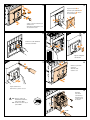
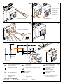
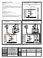
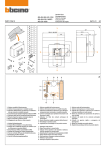
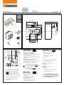
Ma400/630E
mh400/630E
ml400/630E
MS400/630E
part. Y3214B
A
1
4
1
1
1
B
C
D
E
Istruzioni d’uso
Instruction sheet
05/11-01
gf
1
Y
3P=140 - 4P=183
198
70
80
13
=
E
12
34
56
78
D
A
X
=
51
94
X
260
=
141
=
15
105
100
136
Y
C
B
7
5
3
2
1
FUNZION. AUTOMATICO
AUTOMATIC OPERATION
BLOCCO IN APERTO
LOCK IN OPEN POSITION
- Apertura con comando ad impulso
o mantenuto o con il pulsante 4.
- Opening through single impulse or continuous
control or push button 4.
- Impedisce l’esecuzione di manovre.
- Chiusura solo con comando (elettrico) impulsivo
o mantenuto.
- Electrical closing operation only (through
impulsive or continuous control).
Trips the breaker.
- Riarmo mediante motore elettrico o con la leva 1.
- Reset through the motor or with lever 1.
ROSSO
Breaker contacts indicator:
4
6
1 - Leva riarmo manuale / Manual reset lever.
2 - Indicatore molle / Springs indicator:
DISCHARGED
molle scariche / springs unloaded.
CHARGED molle cariche / springs loaded.
Stops any operation.
- Forza lo sgancio dell’interruttore.
6 - Indicatore posizione contatti interruttore:
RED
ROSSO
RED
N.B.:La calotta di copertura non deve
essere rimossa in questa modalità di
funzionamento.
VERDE
GREEN
ATT.:The cover shield must not be removed
in this operation mode.
VERDE
GREEN
FUNZION. MANUALE
MANUAL OPERATION
3 - Pulsante di chiusura / Closing push button.
- Chiusura e apertura esclusivamente tramite i pulsanti (3 e 4).
4 - Pulsante di apertura / Opening push button.
- Closing and opening only through
the push bottons (3 - 4).
5 - Selettore modalità funzionamento /
Mode selector.
- Riarmo esclusivamente con leva (1).
- Reset only through the lever (1).
= chiusi - closed
= aperti - open
7 - Blocco lucchetti in posizione di aperto.
Padlock in open position.
N.B.:Il blocco lucchetti (12) deve essere inserito
per avere abilitate le funzioni “Aut/Man”.
Att.: The padlock (12) have to be pushed inside
to get in “Aut/Man” mode.
2
3
➍
4
Togliere la mostrina ➊ ed
eliminare il primo diaframma ➋.
➌
Take the frame out ➊ and cut
the small window ➋.
➊
➋
➋
Togliere il coperchio interruttore ed
eliminare le viti.
➊
Dismount the small breaker’s cover
and exclude the screws.
5
6
Eliminare il secondo diaframma.
Cut the second window.
➋
➊
➌
C
Applicare la targhetta.
Stick the label.
7
➊
8
➋
Montare il coperchietto
interruttore.
Mount the small
breaker’s cover.
➊
➋
Togliere calotta motore.
Take the motor operator cover out.
9
Montare la
base motore
sull’interruttore.
N.B.:Portare il selettore (5)
modalità di funzionamento,
sulla posizione MAN.
ATT.:Set the mode selector (5) on
position MAN.
Mount the motor
operator base on
the breaker.
B
2 Nm
12
34
56
12
78
34
56
10
78
D
11
Sganciare e premere
(1). Spostare
il selettore (2).
Lucchettare (3).
12
34
56
78
1 Nm
➋
Trip and push (1).
Shift selector (2).
Lock (3).
3
➊
N° 3 max ø 8 mm
Avvitare la calotta motore.
Fix the motor operator cover screws.
12
34
56
12
13
78
➋
Ripristino funzione AUTO/MAN.
AUTO/MAN operation reset.
➊
M7375B
E
34
56
20.5
14
12
Y
A < 23
E
78
3
45
54
CRAC
Y
Q1
Interruttore automatico o di manovra
Automatic C.B. or isolator
M
Contatto protezione coperchio
Contacts for cover’s protection
Comando a motore
Motor operator
S2
Pulsante di apertura / sgancio
Opening / trip push button
Comando a camma - segnale di molle cariche
Cam control - spring loaded indication
D
Contatto ausiliario interruttore
(Art. M5/1CS)
Auxiliary contact MCCB
E
Contatto ausiliario interruttore
(Art. M5/1CS)
Auxiliary contact MCCB
(i)
Relè monostabile 2 N.O.
(Tipo art. FM4A/... FM2AC/....)
Release 2 N.O.
BC
Bobina di chiusura
Closing coil
(ii)
Pulsante monostabile N.O.
(Tipo art. F51NA)
Release N.O.
S1
Pulsante di chiusura
Closing push button
TABELLA COLORI / Colour table:
Bk: Nero / Black Wh: Bianco / White Rd: Rosso / Red
Bl: Blu / Blue
SE
Contatto consenso riarmo volontario
Contact for volontary reset
15
UTILIZZO IN COMMUTAZIONE AUTOMATICA
Attenzione:
in relazione alla modalità di utilizzo del motore con le seguenti combinazioni:
•Senza sganciatore
oppure
•Con sganciatore (M5T/…. O M4M/….)
Comando mantunuto
Switch Operated
Riarmo volontario
Volontary reset
C1C1
C1
Il tempo di commutazione tra linea principale e secondaria (tempo che intercorre
fra l’apertura dell’interruttore della linea principale e la chiusura di quella della
secondaria o viceversa) dovrà essere impostato in modo da risultare maggiore o
uguale rispettivamente a:
•6 secondi
oppure •0,5 secondi
USE FOR AUTOMATIC CHANGEOVER
Chiusura
Closing
Apertura e ricarica
Open and change
1
1
3
3
1
5
3
5 7
7
5
7
MANMAN
MAN
A A
C C
A
C
Q1 Q1
Caution: according to the use mode of the motor that is:
•without tripping device
or
•with tripping device (Bticino M5M/….M4M/….)
B B
Q1
The changeover time between main and secondary line (time between the opening
of the breakers of the main line and the closing of the breakers of the secondary line
and viceversa) should be setted at a value bigger or equal respectively to:
•6 sec
or
•0,5 sec
B
BC BC
M M
BC
M
2
SE SE
D D
2
4
4
6
4
2
SE
D
6 8
8
6
8
Comando impulsivo
Push buttom Operated
Comando impulsivo
Push buttom Operated
Riarmo volontario
Volontary reset
Riarmo automatico dopo lo sgancio
Automatic reset after trip
Chiusura
Closing
S1 S1
Apertura e ricarica
Open and change
(ii) (ii)
(ii)
(ii)
S1 S1
S2
1
1
3
1
3
5
3
(ii)
S2 S2
S2
(i) (i)
(i) (i)
(i)
(i)
5 7
7
5
7
1
1
3
1
3
5
3
57
7
5
7
MANMAN
A A
C C
A
C
MAN
Q1 Q1
Q1
(ii) (ii)
(ii)
S1
MANMAN
MAN
Apertura e ricarica
Open and change
(ii) (ii)
(ii) (ii)
S2 S2
S1
Chiusura
Closing
A A
C C
A
C
14 14 22
12 12
Rd Rd
Wh Wh Rd
12 14
Rd Wh
22
24 24
Rd
Wh Wh
22 24
Rd Wh
Q1 Q1
B B
D D
B
BC BC
M M
BC
M
2
2
2
4
4
Q1
D
6
4
6 8
8
6
8
B B
D D
B
BC BC
M M
BC
M
2
2
2
4
4
4
D
6
68
8
6
8
D D
E E
D
E
Bk Bk
11 11
Bk
11
Bk Bk
21 21
Bk
21
N.B.:Gli schemi indicati nelle figure rappresentano l’interruttore aperto con molle del motore cariche.
Att.: In the figures the C.B. is represented in open position, with spring’s motor loaded.
MORSETTO
LUG
FUNZIONE
FUNCTION
1
Alimentazione di chiusura /
Closing power supply
2
3
4
5
6
7
8
Alimentazione di apertura /
Opening power supply
NO (250
Vac/2A)
Molle cariche /
Spring loaded
Non collegati /
Not connected CARATTERISTICHE / TECHNICAL CHARACTERISTICS
TENSIONE
VOLTAGE
24V dc
48V dc
POTENZA ASSORBITA
TEMPO TOTALE APERTURA + RIPRISTINO
ALLO SPUNTO
TOTAL OPENING TIME + RESET
START INPUT POWER
TEMPO CHIUSURA
CLOSING TIME
300 W
2s
≤ 100 ms
300 VA
2s
≤ 100 ms
24V ac
48V ac
110V ac
230V ac