1
OPERATION AND SERVICE INFORMATION
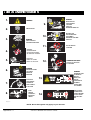
Read all of manual to become thoroughly familiar with this vehicle. Pay particular attention to all Notes, Cautions and Warnings
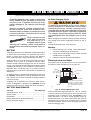
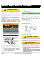
Provide Protection From Elements
The power (AC) c ord is equipped wit h a
grounded plug, do not attempt to pull out, cut or
bend the ground post.
The charging (DC) cord is equipped with a polarized connector which fits into a matching receptacle on the vehicle.
The power (AC) cord is equipped with a grounded plug.
Do not attempt to remove, cut or bend the ground post.
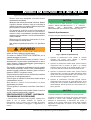
Do Not Block Louvered Airways
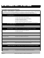
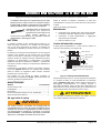
NEMA 15 - 5R Grounded AC Receptacle
110 - 120 VAC. Dedicated 15 AMP Circuit
Locations outside the US and Canada: Reference
appropriate local electrical code and charger manufacturer recommendations for AC power requirements
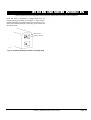
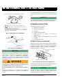
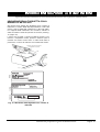
Ref Pci 1
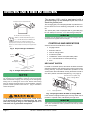
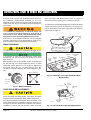
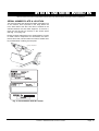
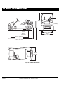
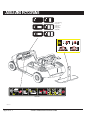
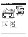
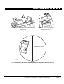
Fig. 2 Proper Charger Installation
Front of
Vehicle
Charger
Receptacle
If vehicle is to be charged with a non E-Z-GO charger, refer to
the instructions supplied with the charger.
CONTROLS AND INDICATORS
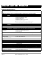
Vehicle controls and indicators consist of:
•
•
•
•
•
•
•
key/light switch
direction selector
state of charge meter
accelerator pedal
combination service and park brake pedal
run - tow/maintenance switch (PDS only)
horn
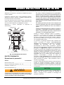
KEY/LIGHT SWITCH
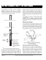
Ref Crl 1
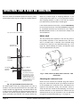
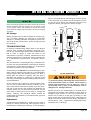
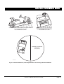
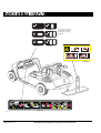
Fig. 3 Charger Receptacle Loation
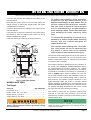
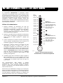
Located on the dash panel, this switch enables the basic
electrical system of the vehicle to be turned on and off by
turning the key. To prevent inadvertent operation of the
vehicle when left unattended, the key should be turned to
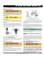
the ‘OFF’ position and removed (Ref Fig. 4 on page 2).
Direction Selector (PDS only)
Looping the DC cord through the steering wheel when charging, serves as a good reminder to store the cord out of the way
when finished with charging. The DC plug can be damaged by
driving over or catching the cord on the vehicle when driving
away. A charging interlock feature on the PowerWise™ charger
prevents vehicle operation while the DC plug is inserted in
vehicle receptacle.
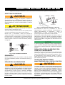
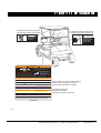
State of Charge Meter
OFF
ON
Ref Kes 1
Key/Light Switch
Fig. 4 Key/Light Switch & State of Charge Meter
To prevent a physical hazard that could result
in an electrical shock or electrocution, be sure
that the charger plug is not damaged and is
inserted into a grounded receptacle.
Page 2
If the vehicle is equipped with lights, the key switch has a
position to operate them, indicated by the light icon.
If the vehicle is equipped with factory installed custom accessories, some accessories remain operational with the key switch
in the ‘OFF’ position.
Owner’s Manual and Service Guide