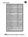
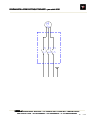
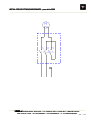
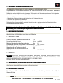
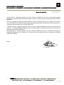
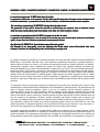
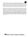
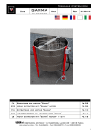
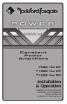
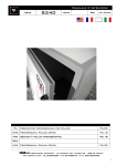
1
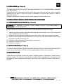
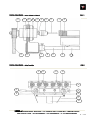
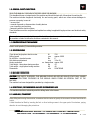
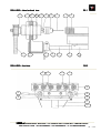
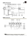
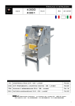
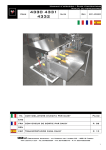
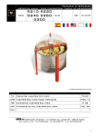
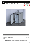
Manuale d’istruzioni
Code
ITA
3040
3060
Matr.
Rev.
20070314
Perforatrice Multipla a 6 mandrini
ENG Electric multiple bit drilling machine
Pg.02
Page 09
FRA Machine électrique à percer les cadres
DEU Mehrfachlocher
Mehrfachlocher für Rähmchen mit 6 Bohrern
Pg.16
Seite 23
LEGA srl Costruzioni Apistiche – via Maestri del Lavoro 23 – 48018 Faenza
www.legaitaly.com - Tel 054626834 – Fax 054628279 – P.iva 00043230390
1
1.0 AVVERTENZE GENERALI SULLA SICUREZZA
LEGGERE ATTENTAMENTE QUESTO MANUALE PRIMA D’UTILIZZARE LA MACCHINA
Questo libretto è parte integrante della macchina e l'accompagna fino alla demolizione.
La macchina presenta parti pericolose perché allacciata alla rete elettrica e dotata di movimento, pertanto
possono causare gravi danni a persone o cose:
-
un uso improprio
la rimozione delle protezioni e lo scollegamento dei dispositivi di protezione
la mancanza d’ispezioni e manutenzioni
la manomissione dell’impianto elettrico
Le istruzioni devono essere integrate ed aggiornate in base alle disposizioni legislative e dalle norme tecniche
di sicurezza vigenti.
La ditta costruttrice non si riterrà responsabile d’inconvenienti, rotture o incidenti dovuti al mancato rispetto o alla
non applicazione delle indicazioni contenute nel presente manuale.
1.1 IDENTIFICAZIONE DELLA MACCHINA
Perforatrice multipla a 6 mandrini per la foratura di telaini
1.2 DATI TECNICI
Potenza motore trifase o monofase
Velocità delle punte
Unità foratrici montate in versione standard
Regolazione quota di foratura dal piano
Produzione oraria telaini forati
Peso complessivo perforatrice trifase
Peso complessivo perforatrice monofase
Dimensioni
W
n/min
N
mm
n/ora
Kg
Kg
mm
750
5000 c.a.
6
da 10 a 40
500 circa
44
48
550x750x85
1.3 PERSONALE
PERSONALE ADDETTO
ATTENZIONE! AI FINI DELLA SICUREZZA QUESTA MACCHINA DEVE ESSERE UTILIZZATA ESCLUSIVAMENTE
DA PERSONALE ADULTO IL QUALE DEVE ESSERE INFORMATO DELLE ISTRUZIONI CONTENUTE IN QUESTO
MANUALE, CHE COSTITUISCE PARTE INTEGRANTE ED ESSENZIALE DELLA MACCHINA.
La lavorazione viene svolta da una sola persona.
1.4 AVVERTENZE / USO PREVISTO E NON PREVISTO
Questa macchina deve essere impiegata esclusivamente per la foratura di telaini.
2.1 MOVIMENTAZIONE / TRASPORTO
Per il sollevamento e lo spostamento della macchina bisogna considerare che Il baricentro della massa è a
circa 2/3 dell'altezza.
Il sollevamento perciò va eseguito con presa nella parte alta della struttura avendo cura di evitare il
danneggiamento delle protezioni.
LEGA srl
Costruzioni Apistiche – via Maestri del Lavoro 23 – 48018 Faenza
www.legaitaly.com - Tel 054626834 – Fax 054628279 – P. iva 00043230390
2 / 33
2.2 INSTALLAZIONE (FIG. 1-2 PAG. 5)
Per questa macchina non sono necessari ancoraggi al pavimento e ciò ne permette l'utilizzo in qualunque
punto del laboratorio.
Il listello di legno (64), fornito assieme alla macchina, deve essere fissato sul piano del carrello in posizione
perpendicolare alle punte. Il listello deve servire a contrastare la pressione della foratura e a dare un
riferimento al telaino.
Collegare la perforatrice ad un'idonea presa di corrente elettrica provvista di messa a terra.
3.0 REGOLAZIONE E MESSA A PUNTO INIZIALE DELLA MACCHINA
3.1 POSIZIONAMENTO DELLE FORATURE (FIG. 1-2 PAG. 5)
ATTENZIONE! LE OPERAZIONI DI MESSA A PUNTO VANNO ESEGUITE A MACCHINA FERMA E A
COLLEGAMENTI ELETTRICI DISINSERITI.
Qualora la distanza fra le punte non corrispondesse a quella desiderata, procedere come segue:
1) Togliere la protezione superiore sollevandola dalla guida dopo avere sbloccato, con la chiave a brugola da
4 mm in dotazione, le due viti sul fronte.
2) Allentare le due viti che fermano la staffa del motore sulla struttura, togliendo così tensione alla cinghia.
3) Spostare le unità secondo necessità allentando le viti (G) poste sulle due alette, facendo scorrere le unità
sulle guide e serrando nuovamente le viti.
4) Posizionare i rullini tendicinghia (40) fermandoli al centro tra due.
5) Ripristinare la tensione alla cinghia.
6) Rimontare la protezione.
3.2 QUOTA DI FORATURA (FIG. 1-2 PAG. 5)
Per registrare l'altezza di foratura, allentare il pomello di bloccaggio (58) posto sul lato destro della macchina e
muovere la leva dell'eccentrico (57) fino a trovare la giusta posizione; bloccare infine il pomello.
4.0 ISTRUZIONI D’USO
Il telaino da forare va posato sul piano del carrello e, trattenuto assieme a quest'ultimo, va spinto verso le
punte per eseguire i fori. Attenzione a non allentare la presa del telaino completamente o da una parte, prima
che questo sia uscito completamente dalle punte, perché in tal caso, si potrebbe rischiare la rottura di una o
più punte.
LEGA srl
Costruzioni Apistiche – via Maestri del Lavoro 23 – 48018 Faenza
www.legaitaly.com - Tel 054626834 – Fax 054628279 – P. iva 00043230390
3 / 33
5.0 MANUTENZIONE (FIG. 1-2 PAG. 5)
ATTENZIONE! LE OPERAZIONI DI MANUTENZIONE VANNO ESEGUITE A MACCHINA FERMA E A
COLLEGAMENTI ELETTRICI DISINSERITI.
La macchina non necessita di particolare manutenzione, salvo un periodico controllo dello stato dei cuscinetti
e della cinghia di trazione.
E' bene che sia le guide del carrello (52) che i relativi eccentrici (51) siano lubrificate con grasso per uso
meccanico.
6.0 POSSIBILI INCONVENIENTI E LORO SOLUZIONE (FIG. 1-2 PAG. 5)
In caso di necessità, il nostro personale tecnico è a Vostra disposizione per comunicazione telefonica o mezzo
fax, negli orari di lavoro, per qualunque informazione o consiglio tecnico relativo alla macchina; comunque
prima di interpellarci, Vi preghiamo di controllare le informazioni sotto riportate.
ATTENZIONE! TOGLIERE TENSIONE PRIMA DI RIMUOVERE I CARTER.
Una punta di foratura si è rotta
1) inserire la chiave in dotazione nel foro (F) che si trova sul perno e, utilizzando questo contrasto, svitare il
mandrino in senso antiorario. Sostituire la punta e serrare con giusta pressione.
Rumorosità anormale
1) Cattivo stato d'uso della cinghia
2) Cuscinetto di un’unità foratrice danneggiato
Per verificare la condizione dei cuscinetti, togliere la cinghia e fare girare a mano ogni unità e cuscinetto
tendicinghia ricercandone l'eventuale difetto.
Dislivello del piano di lavoro
Quando una delle due viti (V) che collegano i bracci di movimento (53-55) ai perni guida (52-54) del carrello
perde il bloccaggio, il piano di legno può non essere più allineato con le punte che forano.
Per rimettere in fase l'eccentrico è necessario svitare ulteriormente la vite lenta, far ruotare il perno guida
relativo fino a ritrovare l'allineamento e serrare infine bene la vite.
Sostituzione di un cuscinetto
1) Togliere tensione alla macchina e rimuovere il carter superiore
2) Allentare o togliere la cinghia di trascinamento (75)
3) Rimuovere, dopo averla sbloccata, l'unità (10) del cuscinetto danneggiato, facendola ruotare di 90°
rispetto alle guide del bancale di staffaggio.
4) Togliere il dado posteriore e la puleggia dentata
5) Con l'aiuto di una pinza per anelli seeger, togliere i seeger anteriore e posteriore
6) Riavvitare parzialmente il dado e battere su questo, con le opportune precauzioni, fino a liberare l'alberino
(12), assieme al cuscinetto anteriore, dal portacuscinetto (11).
7) Estrarre (eventualmente utilizzando un tubo di adatte dimensioni) il cuscinetto danneggiato, sempre con
cura di non danneggiare il perno e sostituirlo.
8) Per il ripristino, eseguire a ritroso le varie operazioni.
LEGA srl
Costruzioni Apistiche – via Maestri del Lavoro 23 – 48018 Faenza
www.legaitaly.com - Tel 054626834 – Fax 054628279 – P. iva 00043230390
4 / 33
TESTA FORATRICE – VISTA SEZIONE LATERALE
LATERALE
13
11
75
20
6
FIG. 1
12
G
20
16
V
17
53
T
52
64
62
6
TESTA FORATRICE – vista frontale
FIG.2
10
40
43
51
20
57
58
55
53
75
100
LEGA srl
Costruzioni Apistiche – via Maestri del Lavoro 23 – 48018 Faenza
www.legaitaly.com - Tel 054626834 – Fax 054628279 – P. iva 00043230390
5 / 33
TABELLA PARTICOLARI
Rif
1
10
11
12
13
15
17
18
20
30
35
40
43
50
51
52
53
55
57
58
60
6
62
64
70
75
90
91
92
93
94
95
96
97
98
100
F
V
S1
T
S2
G
LEGA srl
Descrizione
Testa perforatrice
Unità foratrice
Portacuscinetto unità foratrice
Alberino unità foratrice
Puleggia unità foratrice
Mandrino mm 8 M10 x 1
Punta elicoidale mm 3
Cuscinetto per unità (15,35,11)
Bancale di supporto unità
Carter superiore
Protezione cinghia
Tendicinghia
Cuscinetto tendicinghia (12,32,14)
Gruppo eccentrico
Eccentrico
Perno guida
Braccio destro eccentrico
Braccio sinistro eccentrico
Pomello leva eccentrico
Pomello a vite blocco eccentrico
Carrello
Canotto carrello
Piano in legno carrello
Appoggio per telaino
Puleggia motore perforatrice
Cinghia dentata
Impianto elettrico
Cavo e spina 3 m trifase
Cavo e spina 3 m monofase
Interruttore trifase
Interruttore monofase
Motore trifase
Motore monofase
Supporto motore trifase
Supporto motore monofase
struttura metallica di base
Foro per sblocco mandrino
Vite bloccaggio eccentrico
Seeger per foro mm 35
Telaino
Seeger per albero mm 40
Vite a grano M8 x 16
Codice
3040100
3040110
3040111
3040112
3040113
3040115
3080
65206202
3040120
3040130
3040180
3040140
3040143
3040150
3040151
3040152
3040153
3040154
81440002
81200850
3040160
3040161
3040162
82125050
6790260
6790270
3040190
5000013
5000012
41140003
41140002
43430100
42430100
3040197
3040198
3040200
Sigla
14L050
6202 2RS
62201 2RS
42L050
600L050
4P B3 Hp 1 M71
4P B3 Hp 1 M80
M6
Costruzioni Apistiche – via Maestri del Lavoro 23 – 48018 Faenza
www.legaitaly.com - Tel 054626834 – Fax 054628279 – P. iva 00043230390
6 / 33
SCHEMA IMPIANTO ELETTRICO TRIFASE – per articolo
articolo 3040
M
T1 T2 T3
L1 L2 L3
LEGA srl
Costruzioni Apistiche – via Maestri del Lavoro 23 – 48018 Faenza
www.legaitaly.com - Tel 054626834 – Fax 054628279 – P. iva 00043230390
7 / 33
IMPIANTO ELETTRICO monofase – per articolo 3060
M
T1 T2 T3
L1 L2 L3
LEGA srl
Costruzioni Apistiche – via Maestri del Lavoro 23 – 48018 Faenza
www.legaitaly.com - Tel 054626834 – Fax 054628279 – P. iva 00043230390
8 / 33
1.0 GENERAL SAFETY DIRECTIONS
READ THIS MANUAL THROUGHOUT BEFORE USING THE MACHINE
This handbook forms an integral part of the machine and should be kept with it throughout its working life.
The machine includes dangerous electrically live and moving parts, which can cause serious damages to
persons or property in case of:
- incorrect use
- removal of guards or disconnection of safety devices
- poor inspection and servicing
- tampering with the electric system
These directions must be completed and updated according to applicable legal provisions and technical safety
standards.
The manufacturer may not be held responsible for failures, breaks or accidents resulting from incorrect use of
the machine or failure to follow the directions contained in this manual.
1.1 IDENTIFICATION OF THE MACHINE
Electric multi spindle (6) frame drilling machine.
1.2 SPECIFICATIONS
Three-phase/single-phase electric motor
Drilling speed
No. drill bits – standard version
Hole distance adjustment
Hourly production
Total weight - three-phase boring machine
Total weight - single-phase boring machine
Dimensions
W
rpm
No.
mm
no. frames/hour
Kg
Kg
mm
750
approx. 5000
6
10 to 40
approx. 500
44
48
550x750x85
1.3 MACHINE OPERATORS
CAUTION! FOR SAFETY PURPOSES, THIS MACHINE SHOULD BE USED BY SKILLED STAFF ONLY, AWARE
OF THE INSTRUCTIONS CONTAINED IN THIS MANUAL WHICH FORMS AN INTEGRAL PART OF THE
MACHINE.
The machine has been designed for operation by a single worker.
1.4 DIRECTIONS / RECOMMENDED AND NOT RECOMMENDED USE
This machine should be exclusively used for drilling holes in the frames.
2.1 HANDLING
HANDLING / TRANSPORT
When lifting and moving the machine, remember that the center of gravity of the mass is at about two thirds its
height.
It must therefore be lifted by inserting the fork or other hoisting means in the upper part of its structure, paying
attention to avoid damaging the protections.
LEGA srl
Costruzioni Apistiche – via Maestri del Lavoro 23 – 48018 Faenza
www.legaitaly.com - Tel 054626834 – Fax 054628279 – P. iva 00043230390
9 / 33
2.2 INSTALLAT
INSTALLATION (fig.
fig. 1-2 page
page 5)
It is not necessary to anchor the machine to the ground, and it can be positioned anywhere inside the
workshop.
The wooden strip (64) supplied with the machine, must be fixed to the carriage perpendicular to the drill bits.
The strip serves to resist drilling pressure and as reference point.
Connect the boring machine to a suitable, properly grounded power socket.
3.0 PRELIMINARY OPERATIONS BEFORE USE
3.1 POSITI
POSITION
TION OF HOLES (fig.
fig. 1-2 page
page 5)
CAUTION!
CAUTION! ALL PRELIMINARY OPERATIONS SHOULD BE CARRIED OUT WITH THE MACHINE TURNED OFF
AND ELECTRIC POWER DISCONNECTED.
If the distance between the drill bits does not correspond to that needed, proceed as follows:
1) remove the upper guard by lifting it from the guide rail after loosening the two screws on the front with the 4 mm
wrench supplied with the machine.
2) loosen the two screws that secure the motor bracket to the structure, thus loosening the tension on the belt.
3) move the drill bits as needed by undoing the screws (G) on the two wings, make the bits slide along the guide
rail until in the correct position, then re-do the screws.
4) put the belt tensioner rollers (40) in position and block them.
5) re-tighten the belt.
6) replace the upper guard.
3.2 HOL
HOLE DRILLING HEIGHT (fig. 11-2 page
page 5)
To adjust drilling height, loosen the locking knob (58) on the right of the machine then move the eccentric
lever (57) to the desired position and re-tighten the knob.
4.0 OPERATION INSTRUCTIONS
INSTRUCTIONS
The frame to be drilled must be placed horizontal on the carriage, and then moved together with the carriage,
towards the drill bits. Always make sure not to lose your grip on it, even partially, until the operation is
completed otherwise the drill bits might get damaged or broken.
5.0 MAINTENANCE (FIG. 1-2 PAGE
PAGE 5)
LEGA srl
Costruzioni Apistiche – via Maestri del Lavoro 23 – 48018 Faenza
www.legaitaly.com - Tel 054626834 – Fax 054628279 – P. iva 00043230390
10 / 33
CAUTION! MAINTENANCE OPERATIONS SHOULD BE CARRIED OUT AFTER STOPPING THE MACHINE AND
DISCONNECTING ELECTRIC POWER.
No special maintenance is required, except for regularly checking the status of bearings and belt tensioner.
It is also recommended to lubricate the carriage guide rails (52) and eccentrics (51) with a suitable grease.
6.0 FAULTS, CAUSES AND REMEDIES (fig. 11-2 page
page 5)
Our after-sales staff can be contacted during working hours by telephone or fax for any information or technical advice
in regard to the machine; however, before contacting our after-sales service, please check the information provided here
below.
CAUTION!
CAUTION! DISCONNECT POWER BEFORE REMOVING THE PROTECTION GUARDS.
One of the drill bits got broken
1) insert the wrench (supplied with the machine) in hole (F) on the shaft, and rotate the spindle anti-clockwise.
Replace the bit then re-tighten to proper tension.
Excessive noise
noise
1) The belt is in bad condition
2) A drill bit bearing got damaged
To check for proper condition of bearings, remove the belt and manually rotate the drill bits and belt
tensioner bearings, one by one, to find out which one is not working properly.
The worktable
worktable is not perfectly
perfectly level
If one or both the screws (V) that connect the arms (53-55) to the carriage shaft guides (52-54) get loosen,
the wooden table may be misaligned with the drill bits.
To reset the eccentric, loosen the screw completely, make the guide shaft rotate until alignment is correct then
tighten back the screw.
Bearing replacement
1) Disconnect power then remove the upper guard
2) Loosen tension on the belt (75) or remove it (75)
3) Unlock the drill bit (10) with the damaged bearing, then remove it by rotating it through 90° to the
worktable guide rails
4) Remove the rear nut and the toothed pulley
5) Using Seeger ring pliers, remove the front and rear seeger rings
6) Partially tighten the nut and exert some pressure on it until the shaft (12) can be taken out of the bearing
holder (11) together with the front bearing
7) Take out the damaged bearing (using a pipe section of suitable length if necessary), making sure not to
damage the shaft, then replace it
8) To reassemble, repeat the above procedure in reverse.
LEGA srl
Costruzioni Apistiche – via Maestri del Lavoro 23 – 48018 Faenza
www.legaitaly.com - Tel 054626834 – Fax 054628279 – P. iva 00043230390
11 / 33
DRILL HEAD – lateral sectional view
13
11
75
20
6
FIG. 1
12
G
20
16
V
17
53
T
52
64
62
DRILL HEAD – front view
6
FIG.2
10
40
43
51
20
57
58
55
53
75
100
LEGA srl
Costruzioni Apistiche – via Maestri del Lavoro 23 – 48018 Faenza
www.legaitaly.com - Tel 054626834 – Fax 054628279 – P. iva 00043230390
12 / 33
PART LIST
Rif
1
10
11
12
13
15
17
18
20
30
35
40
43
50
51
52
53
55
57
58
60
6
62
64
70
75
90
91
92
93
94
95
96
97
98
100
F
V
S1
T
S2
G
LEGA srl
Descrizione
Drill head
Drill bit
Drill bit bearing holder
Drill bit shaft
Drill bit pulley
8 mm spindle M10 x 1
3 mm twist drill bit
Dril bit bearing (15, 35, 11)
Drill bit bench
Upper guard
Belt guard
Belt tensioner
Belt tensioner bearing (12, 32, 14)
Eccentric assembly
Eccentric
Guide pin
Eccentric right arm
Eccentric left arm
Eccentric lever knob
Eccentric lock knob
Carriage
Carriage sleeve
Carriage wooden element
Frame support
Drilling machine motor pulley
Toothed belt
Electric system
3 m cable with plug - three-phase motor
3 m cable with plug - single-phase motor
Three-phase switch
Single-phase switch
Three-phase eletric motor
Single-phase electric motor
Three-phase motor mount
Single-phase motor mount
Metal chassis
Spindle release hole
Eccentric lock screw
35 mm hole Seeger
Frame
40 mm shaft Seeger
Dowel screw M8 x 16
Codice
3040100
3040110
3040111
3040112
3040113
3040115
3080
65206202
3040120
3040130
3040180
3040140
3040143
3040150
3040151
3040152
3040153
3040154
81440002
81200850
3040160
3040161
3040162
82125050
6790260
6790270
3040190
5000013
5000012
41140003
41140002
43430100
42430100
3040197
3040198
3040200
Sigla
14L050
6202 2RS
62201 2RS
42L050
600L050
4P B3 Hp 1 M71
4P B3 Hp 1 M80
M6
Costruzioni Apistiche – via Maestri del Lavoro 23 – 48018 Faenza
www.legaitaly.com - Tel 054626834 – Fax 054628279 – P. iva 00043230390
13 / 33
WIRING SYSTEM – threethree-phase motor,
motor, for item 3040
M
T1 T2 T3
L1 L2 L3
LEGA srl
Costruzioni Apistiche – via Maestri del Lavoro 23 – 48018 Faenza
www.legaitaly.com - Tel 054626834 – Fax 054628279 – P. iva 00043230390
14 / 33
WIR
WIRING SYSTEM – singlesingle-phase motor, for item 3060
3060
M
T1 T2 T3
L1 L2 L3
LEGA srl
Costruzioni Apistiche – via Maestri del Lavoro 23 – 48018 Faenza
www.legaitaly.com - Tel 054626834 – Fax 054628279 – P. iva 00043230390
15 / 33
1.0 RECOMMANDATIONS GÉNÉRALES SUR LA SÉCURITÉ
LIRE ATTENTIVEMENT CE GUIDE AVANT D'UTILISER LA MACHINE
Ce guide fait partie intégrante de la machine et l'accompagne jusqu'à sa démolition.
La machine présente des parties dangereuses car elle est branchée au réseau électrique et comprend des
organes en mouvement, elle peut donc causer de graves dommages aux personnes ou aux biens dans les
situations suivantes :
-
une utilisation impropre ;
le retrait des protections et le débranchement des dispositifs de protection ;
le manque d'inspections et de maintenance ;
la modification de l'installation électrique.
Les instructions doivent être complétées et actualisées en fonction des dispositions législatives et des normes
techniques de sécurité en vigueur.
non--respect ou
Le constructeur ne sera aucunement responsable en cas de problèmes, ruptures ou accidents dus au non
à la nonnon-application des recommandations
recommandations contenues dans ce guide.
1.1 IDENTIFICATION DE LA MACHINE
Machine à électrique à percer les cadres à 6 mandrins pour la perforation de cadres
1.2 DONNÉES TECHNIQUES
Puissance moteur triphasé ou monophasé
Vitesse des forets
Unité perceuses montées en version standard
Réglage épaisseur de perçage
Production horaire cadres perforés
Poids total machine à percer triphasée
Poids total machine à percer monophasée
Dimensions
W
tr/min
n.
mm
n/h
Kg
Kg
mm
750
5000 env.
6
de 10 à 40
500 environ
44
48
550x750x85
1.3 PERSONNEL PRÉPOSÉ
ATTENTION ! AFIN DE GARANTIR LA SÉCURITÉ, CETTE MACHINE DOIT ÊTRE UTILISÉE EXCLUSIVEMENT
PAR DU PERSONNEL ADULTE QUI DOIT ÊTRE À CONNAISSANCE DES INSTRUCTIONS CONTENUES DANS
CE GUIDE, QUI CONSTITUE UNE PARTIE INTÉGRANTE ET ESSENTIELLE DE LA MACHINE.
Le travail est effectué par une seule personne.
1.4 RECOMMENDATIONS/UTILISATION
RECOMMENDATIONS/UTILISATION PRÉVUE ET NON PRÉVUE
Cette machine doit être exclusivement utilisée pour le perçage de cadres.
2.1 MANUTENTION/TRANSPORT
Pour le levage et le déplacement de la machine il faut tenir compte du fait que le barycentre de la masse est à
environ 2/3 de la hauteur.
Le levage doit donc être effectué en faisant prise sur la partie haute de la structure en ayant soin d'éviter
d'endommager les protections.
LEGA srl
Costruzioni Apistiche – via Maestri del Lavoro 23 – 48018 Faenza
www.legaitaly.com - Tel 054626834 – Fax 054628279 – P. iva 00043230390
16 / 33
2.2 INSTALLATION (fig. 11-2 page 5)
Cette machine n'a pas besoin d'ancrages au sol et cela permet de l'utiliser n'importe où dans le laboratoire.
La baguette en bois (64), fournie avec la machine, doit être fixée sur le plan du chariot perpendiculairement
aux forets. La baguette doit servir de butée de contraste à la pression de perçage et de repère au cadre.
Brancher la machine à percer dans une prise de courant électrique adaptée munie de mise à la terre.
3. 0 RÉGLAGE INITIAL ET PREMIÈRE MISE AU POINT DE LA MACHINE
3.1 POSITIONNEMENT DES PERÇAGES (fig. 11-2 page. 5)
ATTENTION ! LES OPÉRATIONS DE MISE AU POINT DOIVENT ÊTRE EFFECTUÉES AVEC LA MACHINE
ARRÊTÉE ET DÉBRANCHÉE DU RÉSEAU ÉLECTRIQUE.
Si la distance entre les forets n'est pas la distance voulue, procéder comme suit :
1) Enlever la protection supérieure en la soulevant de son guidage après avoir débloqué avec la clé Allen de
4 mm fournie, les deux vis sur le devant.
2) Desserrer les deux vis qui fixent l'étrier du moteur sur la structure, diminuant ainsi la tension de la
courroie.
3) Déplacer les unités en fonction des nécessités en desserrant les vis (G) qui se trouvent sur les deux
ailettes en faisant coulisser les unités sur les guidages et en serrant de nouveau les vis.
4) Positionner les galets tendeurs de courroie (40).
5) Rétablir la tension de la courroie.
6) Remonter la protection.
3.2 DIMENSION DE PERÇAGE (fig. 11-2 page. 5)
Pour régler la hauteur de perçage, desserrer le bouton de blocage (58) placé sur le côté droit de la machine et
déplacer le levier de l'excentrique (57) jusqu'à trouver la bonne position ; Enfin bloquer le bouton.
4.0 INSTRUCTIONS D’UTILISATION
Le cadre à percer doit être posé sur le plan du chariot et en le maintenant solidaire à celui-ci, il doit être
poussé vers les forets pour l’exécution des trous. Attention à ne pas lâcher la prise du cadre complètement ou
d'un côté, avant que celui-ci ne soit complètement sorti des forets, parce que cela risquerait de casser un ou
plusieurs forets.
5.0 MAINTENANCE
MAINTENANCE (fig. 11-2 page. 5)
ATTENTION ! LES OPÉRATIONS DE MAINTENANCE DOIVENT ÊTRE EFFECTUÉES AVEC LA MACHINE
ARRÊTÉE ET DÉBRANCHÉE DU RÉSEAU ÉLECTRIQUE.
La machine ne nécessite pas d'une maintenance particulière, mais simplement d'un contrôle périodique de
l'état des paliers et de la courroie de traction.
Il est conseillé de graisser avec une graisse mécanique les guidages du chariot (52) et leurs excentriques
(51).
LEGA srl
Costruzioni Apistiche – via Maestri del Lavoro 23 – 48018 Faenza
www.legaitaly.com - Tel 054626834 – Fax 054628279 – P. iva 00043230390
17 / 33
6.0 PROBLÈMES POSSIBLES ET SOLUTIONS. 11-2 page 5)
Si nécessaire, notre personnel technique est à votre disposition, par téléphone ou par fax, durant les horaires
de travail, pour toute information ou tout conseil technique relatif à la machine ; néanmoins avant de nous
contacter, nous vous prions de contrôler les informations ci-après.
ATTENTION ! COUPER LE COURANT AVANT DE RETIRER LES CARTERS.
Un foret de perçage s'est cassé
1) introduire la clé fournie avec la machine dans le trou (F) qui se trouve sur l'axe et dévisser le mandrin dans le
sens inverse aux aiguilles d'une montre. Remplacer le foret et serrer correctement.
Niveau de bruit anormal
1) Courroie usée
2) Palier d'une unité de perçage endommagé
Pour vérifier l’état des paliers, enlever la courroie et faire tourner manuellement chaque unité et chaque
palier tendeur de courroie en cherchant le défaut éventuel.
Désalignement du plan de travail
Quand une des deux vis (V) qui relient les bras de mouvement (53-55) aux axes de guidage (52-54) du
chariot perd le blocage, le plan de de bois peut ne plus être aligné avec les forets.
Pour réajuster l'excentrique il est nécessaire de dévisser encore la vis lente, faire tourner le goujon de guidage
concerné jusqu'à retrouver l'alignement et enfin bien serrer la vis.
Remplacement d'un palier
1) Couper le courant à la machine et enlever le carter supérieur
2) Desserrer ou enlever la courroie d'entraînement (75)
3) Après l'avoir débloquée, enlever l'unité (10) du palier endommagé, en la faisant tourner de 90 ° par
rapport aux guidages de la palette de fixation.
4) Enlever l'écrou arrière et la poulie dentée
5) À l'aide d'une pince pour anneaux Seeger, enlever les anneaux avant et arrière.
6) Revisser partiellement l'écrou et frapper dessus, en prenant les précautions nécessaires, jusqu’à libérer la
tige (12) et le palier avant du support de palier(11).
7) Extraire (éventuellement à l'aide d'un tube des dimensions appropriées) le palier endommagé, toujours en
ayant soin de ne pas endommager l'axe et le remplacer.
8) Pour remonter, effectuer ces opérations à l'inverse.
LEGA srl
Costruzioni Apistiche – via Maestri del Lavoro 23 – 48018 Faenza
www.legaitaly.com - Tel 054626834 – Fax 054628279 – P. iva 00043230390
18 / 33
TÊTE DE PERÇAGE
PERÇAGE – vue latérale
13
11
75
20
6
FIG. 1
12
G
20
16
V
17
53
T
52
64
62
6
TÊTE DE PERÇAGE – vue frontale
FIG. 2
10
40
43
51
20
57
58
55
53
75
100
LEGA srl
Costruzioni Apistiche – via Maestri del Lavoro 23 – 48018 Faenza
www.legaitaly.com - Tel 054626834 – Fax 054628279 – P. iva 00043230390
19 / 33
TABLEAU DES COMPOSANTS
Réf
1
10
11
12
13
15
17
18
20
30
35
40
43
50
51
52
53
55
57
58
60
6
62
64
70
75
90
91
92
93
94
95
96
97
98
100
F
V
S1
T
S2
G
LEGA srl
Description
Tête de perçage
Unité de perçage
Support de palier unité de perçage
Axe unité de perçage
Poulie unité de perçage
Broche 8 M10 x 1 mm
Foret hélicoïdal 3 mm
Palier pour unités (15,35,11)
Palette de support unité
Carter supérieur
Protection courroie
Tendeur de courroie
Palier tendeur de courroie (12,32,14)
Groupe excentrique
Excentrique
Axe de guidage
Bras droit excentrique
Bras gauche excentrique
Bouton levier excentrique
Bouton à vis blocage excentrique
Chariot
Fourreau chariot
Plan en bois du chariot
Appui pour cadre
Poulie moteur machine à percer
Courroie dentée
Installation électrique
Câble et fiche 3 m triphasés
Câble et fiche 3 m monophasés
Interrupteur triphasé
Interrupteur monophasé
Moteur triphasé
Moteur monophasé
Support moteur triphasé
Support moteur monophasé
Structure métallique de base
Trou pour déblocage broche
Vis de blocage excentrique
Seeger pour trou 35 mm
Cadre
Seeger pour arbre 40 mm
Goujon M8 x 16
Code
3040100
3040110
3040111
3040112
3040113
3040115
3080
65206202
3040120
3040130
3040180
3040140
3040143
3040150
3040151
3040152
3040153
3040154
81440002
81200850
3040160
3040161
3040162
82125050
6790260
6790270
3040190
5000013
5000012
41140003
41140002
43430100
42430100
3040197
3040198
3040200
Sigle
14L050
6202 2RS
62201 2RS
42L050
600L050
4P B3 Hp 1 M71
4P B3 Hp 1 M80
M6
Costruzioni Apistiche – via Maestri del Lavoro 23 – 48018 Faenza
www.legaitaly.com - Tel 054626834 – Fax 054628279 – P. iva 00043230390
20 / 33
SCHÉMA INSTALLATION ÉLECTRIQUE TRIPHASÉE – pour article 3040
M
T1 T2 T3
L1 L2 L3
LEGA srl
Costruzioni Apistiche – via Maestri del Lavoro 23 – 48018 Faenza
www.legaitaly.com - Tel 054626834 – Fax 054628279 – P. iva 00043230390
21 / 33
INSTALLATION ÉLECTRIQUE MONOPHASÉE – pour article 3060
M
T1 T2 T3
L1 L2 L3
LEGA srl
Costruzioni Apistiche – via Maestri del Lavoro 23 – 48018 Faenza
www.legaitaly.com - Tel 054626834 – Fax 054628279 – P. iva 00043230390
22 / 33
1.0 ALLGEMEINE SICHERHEITSHINWEISE DEUTSCH
VOR BENUTZEN DER MASCHINE IST DIESES HANDBUCH AUFMERKSAM ZU LESEN
Dieses Handbuch ist wesentlicher Bestandteil der Maschine und muss bis zur Verschrottung aufbewahrt
werden.
Die Maschine umfasst gefährliche und sich bewegende Teile und ist an das Stromnetz angeschlossen. Durch folgendes
Verhalten können schwere Personen- und Sachschäden entstehen:
- Unsachgemäße Benutzung
- Entfernung der Schutzvorrichtungen und Unterbrechung der Schutzmechanismen
- Unterlassen der Inspektionen und Wartungen
- Veränderung der elektrischen Anlage
Die Anweisungen müssen gemäß der gesetzlichen Vorschriften und der gültigen technischen Sicherheitsrichtlinien
vervollständigt und aktualisiert werden.
Das Herstellerunternehmen übernimmt keine Haftung für Störungen, Beschädigungen oder Unfälle, die in Folge der
Handbuchess entstehen.
Nichtbeachtung oder Nichtanwendung der Vorgaben dieses Handbuche
1.1 MASCHINENBESCHREIBUNG
Mehrfachlocher mit 6 Bohrfuttern zum Lochen von Rähmchen
1.2 TECHNISCHE DATEN
Leistung Drehstrom- oder Wechselstrommotor W
750
Drehgeschwindigkeit der Bohrer
U/min
ca. 5000
Montierte Bohreinheiten in der Standardversion
Einstellung der Höhe der Bohreinheiten ab Arbeitsplatte
Stundenproduktion gelochter Rähmchen
Gesamtgewicht des Drehstromlochers Kg
Gesamtgewicht des Wechselstromlochers Kg
Größe
Anz.
mm
Anz./Std
44
48
mm
6
von 10 bis 40
500 circa
550x750x85
1.3 PERSONAL
ACHTUNG! ACHTUNG! AUS SICHERHEITSGRÜNDEN DARF DIESE MASCHINE AUSSCHLIESSLICH VON
ERWACHSENEN BEDIENT WERDEN, WELCHE ÜBER DEN INHALT DIESES HANDBUCHES, DAS
WESENTLICHER BESTANDTEIL DER MASCHINE IST, INFORMIERT SIND.
Die Arbeit wird nur von einer Person ausgeführt.
1.4 WARNHINWEISE / VORGESEHENER UND NICHT VORGESEHENER EINSATZ
Diese Maschine ist ausschließlich zum Lochen von Rähmchen gedacht.
2.1 BEFÖRDERUNG / TRANSPORT
Beim Anheben und Verschieben der Maschine ist zu beachten, dass der Schwerpunkt auf ungefähr auf 2/3 der
Gesamthöhe liegt.
LEGA srl
Costruzioni Apistiche – via Maestri del Lavoro 23 – 48018 Faenza
www.legaitaly.com - Tel 054626834 – Fax 054628279 – P. iva 00043230390
23 / 33
Die Maschine ist daher am oberen Teil anzuheben, dabei ist darauf zu achten, dass die Schutzvorrichtungen
nicht beschädigt werden.
LEGA srl
Costruzioni Apistiche – via Maestri del Lavoro 23 – 48018 Faenza
www.legaitaly.com - Tel 054626834 – Fax 054628279 – P. iva 00043230390
24 / 33
2.2 INSTALLATION (Abb. 11-2 S. 5)
Diese Maschine erfordert keine Verankerung im Boden, daher kann sie an einem beliebigen Platz im Labor
aufgestellt werden.
Die Holzleiste (64), die mit der Maschine geliefert wird, muss im rechten Winkel zu den Bohrern auf der
Arbeitsplatte des Gestells befestigt werden. Die Leiste wirkt als Widerstand gegen den Druck des Bohrens und
gilt gleichzeitig als Bezugsmaß für die Rähmchen.
Schließen Sie den Rähmchenlocher an eine geeignete und geerdete Steckdose an.
3.0 ANFANGSEINSTELLUNG UND -EINRICHTUNG DER MASCHINE
3.1 POSITIONIERUNG DER BOHRLÖCHER
BOHRLÖCHER (Abb. 11-2 S. 5)
ACHTUNG! ALLE EINSTELLUNGSARBEITEN MÜSSEN BEI STILLSTEHENDER UND AN DER VOM STROMNETZ
GETRENNTEN MASCHINE DURCHGEFÜHRT WERDEN.
Sollte der Abstand zwischen den Bohrern geändert werden, so gilt die folgende Vorgehensweise:
1) Mit dem mitgelieferten 4-mm-Imbusschlüssel die beiden Schrauben an der Vorderseite lösen und die
Schutzabdeckung von der Führungsschiene abnehmen.
2) Die beiden Schrauben, mit denen der Motorhalter am Gestell befestigt ist, lösen und den Riemen lockern.
3) Die Bohrfutter wie gewünscht verschieben, indem die Schrauben (G) auf den beiden Flügeln gelockert
werden, so dass die Bohrfutter auf den Schienen bewegt werden können, die Schrauben dann wieder
anziehen.
4) Die Riemenspanner (40) in die richtige Position bringen und feststellen.
5) Den Riemen erneut spannen.
6) Die Schutzvorrichtung erneut befestigen.
3.2 BOHRERHÖHE (Abb. 11-2 S. 5)
Um die Höhe der Bohreinheiten einzustellen, das Befestigungsrad (58) auf der rechten Seite der Maschine
lösen und den Hebel des Exzenters (57) bewegen, bis die richtige Position gefunden ist; am Schluss das Rad
feststellen.
4.0 GEBRAUCHSANWEISUNGEN
Das zu lochende Rähmchen wird auf die Platte des Gestells gelegt und zusammen mit ihm zu den Bohrern geführt. Es
ist darauf zu achten, dass das Rähmchen gleichmäßig zu den Bohrer geführt wird, bis die Bohrer komplett durch den
Rahmen gestoßen sind, ansonsten könnten eine oder mehrere Bohrer Schaden nehmen.
5.0 WARTUNG (Abb. 11-2 S. 5)
ACHTUNG! ACHTUNG! DIE WARTUNGSARBEITEN DÜRFEN NUR BEI STILLSTEHENDER UND VOM
STROMNETZ GETRENNTER MASCHINE AUSGEFÜHRT WERDEN.
Die Maschine benötigt keine besonderen Wartungsarbeiten, allein der Zustand der Lager und des Riemens
müssen regelmäßig überprüft werden.
Die Führungsschienen des Gestells (52) und die entsprechenden Ekzenter (51) sollten mit Maschinenfett
geschmiert werden.
LEGA srl
Costruzioni Apistiche – via Maestri del Lavoro 23 – 48018 Faenza
www.legaitaly.com - Tel 054626834 – Fax 054628279 – P. iva 00043230390
25 / 33
6.0 MÖGLICHE STÖRUNGEN UND ABHILFEN (Abb. 11-2 S. 5)
Bei Bedarf sind unsere Techniker während der Bürozeiten per Telefon oder Fax erreichbar und stehen Ihnen für
Informationen oder technische Auskünfte in Bezug auf das Gerät gerne zur Verfügung. Wir bitten Sie, sich die
nachfolgenden Informationen anzusehen, bevor Sie sich mit uns in Verbindung setzen.
ACHTUNG! VOR ENTFERNEN DES GEHÄUSES DIE NETZSPANNUNG UNTERBRECHEN.
Eine Bohrspitze ist kaputt
1) Den mitgelieferten Schlüssel in die Öffnung (F) auf dem Stift einführen und das Bohrfutter gegen den
Uhrzeigersinn drehen. Den Bohrer austauschen und mit dem richtigen Druck anziehen.
Ungewöhnliche Geräusche
1) Schlechter Zustand des Riemens
2) Das Lager eines Bohrers ist beschädigt
Zur Überprüfung des Zustands der Lager den Riemen lösen und jeden Bohrer und jedes
Riemenspannerlagers per Hand drehen, um den eventuellen Schaden zu suchen.
Ungerade Arbeitsplatte
Wenn eine der beiden Schrauben (V), die die Arme (53-55) verbinden, nicht richtig an den Führungsstiften
(52-54) des Gestells befestigt ist, könnte die Holzarbeitsplatte schief zu den Bohrerspitzen sein.
Um den Ekzenter wieder einzustellen die Schraube erneut lösen und den entsprechenden Führungsstift solange
drehen, bis die Platte wieder gerade ist, am Schluss die Schraube wieder fest anziehen.
Austausch eines Lagers
1) Die Maschine vom Stromnetz trennen und das obere Gehäuse abnehmen
2) Den Riemen (75) lockern oder entfernen
3) Nach dem Lösen das beschädigte Lager (10) entfernen, indem es um 90° zu den Führungsschienen der
Befestigungseinheit gedreht wird.
4) Die hintere Mutter und die gezahnte Riemenscheibe entfernen
5) Mit einer Zange für Seeger-Ringe die vorderen und hinteren Seeger-Ringe entfernen
6) Die Mutter wieder ein wenig aufschrauben und mit vorsichtig Schlägen die Welle (12) zusammen mit dem
vorderen Lager vom Lagerfutter (11) befreien.
7) Das beschädigte Lager (eventuell mittels eines geeigneten Rohrs) entfernen und ein neues einsetzen,
dabei darauf achten, den Stift nicht zu beschädigen.
8) Zum Wiedereinbau, die oben genannten Schritte umgekehrt ausführen.
LEGA srl
Costruzioni Apistiche – via Maestri del Lavoro 23 – 48018 Faenza
www.legaitaly.com - Tel 054626834 – Fax 054628279 – P. iva 00043230390
26 / 33
BORHKOPF – Seitlicher Querschnitt
13
11
20
ABB. 1
6
12
16
17
53
T
52
64
62
BORHKOPF
BORHKOPF – Ansicht von vorne
6
ABB.2
10
40
43
55
75
100
LEGA srl
Costruzioni Apistiche – via Maestri del Lavoro 23 – 48018 Faenza
www.legaitaly.com - Tel 054626834 – Fax 054628279 – P. iva 00043230390
27 / 33
TABELLE EINZELTEILE
Bez.
1
10
11
12
13
15
17
18
20
30
35
40
43
50
51
52
53
55
57
58
60
6
62
64
70
75
90
91
92
93
94
95
96
97
98
100
F
V
S1
T
Beschreibung
Bohrkopf
Bohreinheit
Lagergehäuse der Bohreinheit
Welle der Bohreinheit
Riemenscheibe der Bohreinheit
Bohrfutter mm 8 M10 x 1
Schraubenspitze mm 3
Lager für Einheit (15,35,11)
Platte mit Bohreinheiten
Oberes Gehäuse
Riemenabdeckung
Riemenspanner
Lager Riemenspanner (12,32,14)
Exzentergruppe
Exzenter
Führungstift
Rechter Exzenterarm
Linker Exzenterarm
Knauf Exzenterhebel
Schraubrad zur Blockierung des Exzenters
Gestell
Rohrhülse des Gestells
Holzplatte des Gestells
Rähmchenhalter
Riemenscheibe des Bohrermotors
Zahnriemen
Elektrische Anlage
3 m Kabel mit Stecker Drehstrom
3 m Kabel mit Stecker Wechselstrom
Drehstromschalter
Wechselstromschalter
Drehstrommotor
Wechselstrommotor
Halterung Drehstrommotor
Halter Wechselstrommotor
Grundgestell aus Metall
Öffnung zum Lösen des Bohrfutters
Befestigungsschraube für Exzenter
Seegerring für 35-mm-Öffnung
Rähmchen
LEGA srl
Nummer
3040100
3040110
3040111
3040112
3040113
3040115
3080
65206202
3040120
3040130
3040180
3040140
3040143
3040150
3040151
3040152
3040153
3040154
81440002
81200850
3040160
3040161
3040162
82125050
6790260
6790270
3040190
5000013
5000012
41140003
41140002
43430100
42430100
3040197
3040198
3040200
Abk.
14L050
6202 2RS
62201 2RS
42L050
600L050
4P B3 Hp 1 M71
4P B3 Hp 1 M80
M6
Costruzioni Apistiche – via Maestri del Lavoro 23 – 48018 Faenza
www.legaitaly.com - Tel 054626834 – Fax 054628279 – P. iva 00043230390
28 / 33
S2
G
Seegerring für 40-mm-Welle
Madenschraube M8 x 16
SCHALTPLAN DREHSTROMDREHSTROM-ELEKTROANLAGE - für Artikel 3040
M
T1 T2 T3
L1 L2 L3
LEGA srl
Costruzioni Apistiche – via Maestri del Lavoro 23 – 48018 Faenza
www.legaitaly.com - Tel 054626834 – Fax 054628279 – P. iva 00043230390
29 / 33
WechselstromWechselstrom-ELEKTROANLAGE - für Artikel 3060
M
T1 T2 T3
L1 L2 L3
LEGA srl
Costruzioni Apistiche – via Maestri del Lavoro 23 – 48018 Faenza
www.legaitaly.com - Tel 054626834 – Fax 054628279 – P. iva 00043230390
30 / 33
DICHIARAZIONE DI CONFORMITA’
DECLARATION OF CONFORMITY / DÉCLARATION DE CONFORMITÉ / KONFORMITÄTSERKLÄRUNG
Numero di matricola
La ditta LEGA srl - Costruzioni Apistiche con sede in Faenza, Via Maestri del Lavoro 23, fornitrice della seguente
macchina: art. 3040/3060 Perforatrice trifase/monofase dichiara che essa è conforme a quanto prescritto dalle Direttive
2006/42/CE.
LEGA srl - Costruzioni Apistiche with registered office in Faenza, Via Maestri del Lavoro 23, supplier of the machine:
item 3040/3060 Electric multiple bit drilling machine three-phase/single-phase, declares that the above machinery is in
compliance with the provisions of the Directive 2006/42/CE.
L’entreprise LEGA srl - Costruzioni Apistiche, ayant son siège à Faenza, Via Maestri del Lavoro 23, productrice de la
machine : art. 3040/3060 Machine électrique à percer les cadres triphasè/monophasé déclare qu’elle est conforme aux
prescriptions des directives 2006/42/CE.
Die Firma LEGA srl - Costruzioni Apistiche mit Sitz in Faenza, Via Maestri del Lavoro 23, Lieferfirma des Geräts: Art.
3040/3060 Mehrfachlocher für Rähmchen mit 6 Bohrern erklärt, dass dieses Gerät den Vorschriften der Richtlinie
2006/42/EG entspricht.
Faenza
LEGA srl
LEGA srl
Costruzioni Apistiche – via Maestri del Lavoro 23 – 48018 Faenza
www.legaitaly.com - Tel 054626834 – Fax 054628279 – P. iva 00043230390
31 / 33
24--MONATIG GARANTIE
GARANZIA 24 MESI / 24 MONTHS WARRANTY / GARANTIE DE 24 MOIS / 24
La macchina ha garanzia 24 MESI dalla data di vendita.
assistenza
nza o di
La garanzia è valida solo se al momento del ritiro della macchina da parte del nostro centro assiste
un tecnico autorizzato, si presenta la ricevuta fiscale o fattura, a testimonianza dell’avvenuto acquisto.
The machinery is guaranteed 24 MONTHS starting from the date of sale.
The guarantee is only valid if, when the machine is collected by our customer care or technical service
staff, the owner can produce proof of purchase in the form of a fiscal receipt or invoice.
La machine est garantie pendant 24 MOIS à compter de la date de vente.
La garantie n’est valable que si, lors du retrait de la machine
après--vente ou un technicien
machine par notre service après
agréé, le reçu fiscal ou la facture est présenté comme preuve d’achat.
Das Gerät ist 24 MONATE ab Verkaufsdatum durch Garantie gedeckt.
Die Garantie ist nur dann gültig, wenn bei Abholung des Geräts durch
durch unsere Servicestelle oder einen
befugten Techniker der Zahlungsbeleg oder die Rechnung vorgelegt wird.
La garanzia comprende la riparazione o la sostituzione gratuita dei componenti della macchina riconosciuti difettosi di
fabbricazione o nel materiale, dalla ditta Lega o da una persona espressamente autorizzata. La garanzia decade per i
danni provocati da incuria, uso errato o non conforme alle avvertenze riportate nel manuale d’istruzioni, per incidenti,
manomissioni, riparazioni errate o effettuate con ricambi non originali Lega, riparazioni effettuate da persone non
autorizzate dalla ditta Lega srl, danni intervenuti durante il trasporto da e per il cliente. Sono escluse dalla garanzia tutti i
componenti elettrici (motori elettrici, comandi ecc.), tutte quelle parti soggette ad un normale logorio e le parti estetiche.
Tutte le spese di manodopera, d’imballo, spedizione e trasporto sono a carico del cliente. Qualsiasi pezzo difettoso
sostituito, diverrà di nostra proprietà. Un eventuale guasto o difetto avvenuto nel periodo di garanzia o dopo lo scadere
dello stesso, non dà in nessun caso diritto al cliente di sospendere il pagamento o a qualsiasi sconto sul prezzo della
macchina. In ogni caso la ditta Lega srl non si assume alcuna responsabilità per danni derivanti dall’uso improprio della
macchina.
The guarantee includes free-of-charge repairing and replacement of any part of the machinery that is found to have
manufacturing or material defects by the manufacturer or the manufacturer’s authorised person. This guarantee shall not
apply to damages caused by negligence, misuse or use not in compliance with the directions contained in the
instruction manual, as well as in case of accidents, alteration, tampering, wrong repairing or repairing with non-original
parts, repairing by persons not authorised by Lega s.r.l. and damages during transport to/from the purchaser’s. All
electric parts (electric motors, controls etc.) and parts exposed to normal wear and tear as well as aesthetic parts are
also not covered by the guarantee. All labour, packing, forwarding and transport charges shall be borne by the
purchaser. Any defective parts which have been replaced shall be retained by and become the property of LEGA S.R.L.
Any breakdown or defect which should occur during the guarantee period or after its last date shall not in any case
entitle the purchaser to suspend the payments nor to any discount off the price of the machine. In any case, Lega s.r.l.
shall not be held responsible for any damages resulting from the incorrect use of the machinery.
La garantie comprend la réparation ou le remplacement gratuit des composants de la machine reconnus comme
défectueux (défauts de fabrication ou du matériau) par l’entreprise Lega ou par une personne expressément agréée. La
garantie est annulée si les dommages ont été causés par la négligence, une utilisation incorrecte ou non conforme aux
recommandations fournies dans le guide d’utilisation, des accidents, des modifications, des réparations incorrectes ou
LEGA srl
Costruzioni Apistiche – via Maestri del Lavoro 23 – 48018 Faenza
www.legaitaly.com - Tel 054626834 – Fax 054628279 – P. iva 00043230390
32 / 33
effectuées par des personnes non autorisées par Lega srl, dommages intervenus durant le transport en provenance et
vers le client. Sont exclus de la garantie tous les composants électriques (moteurs électriques, commandes etc.), toutes
les parties sujettes à une usure normale et les parties esthétiques. Tous les frais de main-d’œuvre, d’emballage,
d’expédition et de transport sont à la charge du client. Toute pièce défectueuse remplacée devient notre propriété.
Aucune panne éventuelle ni défaut se produisant durant ou après la période de garantie ne donne le droit au client
d'interrompre le paiement ni de prétendre une quelconque remise sur le prix de la machine. Dans tous les cas,
l’entreprise Lega srl décline toute responsabilité en cas de dommages dérivant d’une utilisation impropre de la machine.
Die Garantie umfasst die Reparatur oder den kostenlosen Austausch der Geräteteile, deren Herstellungs- oder
Materialmängel von der Firma Lega oder einer von ihr ausdrücklich befugten Person anerkannt wurden. Die Garantie
verfällt bei Schäden, die durch Nachlässigkeit, falschen oder nicht den im Handbuch angeführten Anweisungen
entsprechenden Gebrauch, durch Unfälle, mutwillige Änderungen, falsche Reparaturen oder Einsatz von Nicht-OriginalErsatzteilen von Lega, durch Reparaturen, die nicht von durch Lega srl befugtem Personal vorgenommen wurden bzw.
beim Transport sowohl bei der Fahrt zum als auch vom Kunden entstehen. Ausgeschlossen von der Garantie sind alle
Elektroteile (Elektromotoren, Steuerteile usw.), alle Verschleißteile und Ästhetikteile. Alle Kosten für Arbeitskräfte,
Verpackung, Spedition und Transport gehen zulasten des Kunden. Alle ausgetauschten defekten Teile gehen in unser
Eigentum über. Eventuelle Störungen oder Defekte, die während der Garantielaufzeit oder nach deren Ablauf auftreten,
geben dem Kunden keinesfalls das Recht, die Zahlung aufzuheben bzw. irgendwelche Rabatte auf das Gerät zu erzielen.
Die Firma Lega srl übernimmt auf jeden Fall keine Verantwortung für Schäden, die aus einem sachwidrigen Gebrauch
des Geräts entstehe.
LEGA srl
Costruzioni Apistiche – via Maestri del Lavoro 23 – 48018 Faenza
www.legaitaly.com - Tel 054626834 – Fax 054628279 – P. iva 00043230390
33 / 33