1
THE PLASMON 8000 SERIES
AUTOLOADER LF 8120
USER MANUAL
P/N 97664106 A
Storing More Of Your
Digital World ™. Permanently.
Reproduction of this manual, or any portion of this manual, is prohibited without the express permission of
Plasmon Laser Magnetic Storage (LMS). Plasmon LMS reserves the right to make changes in this
document and the product referred to herein without prior notice.
©
2000 Plasmon Laser Magnetic Storage
WARNING
Always observe the following when installing, operating or maintaining
this product:
•
This unit must be connected to a power distribution system that has a
direct connection to earth ground (Terminated Terra [TT] network/
ground connected). This unit is not suitable for use on a floating
ground (Interrupted Terra [IT]) network.
•
The AC input power cord must be shielded and must have a minimum
current rating of 10 A with a nominal cross-section area of 0.75 sq mm
(reference: AWG #18) per conductor, 2 wires plus ground and product
safety approvals as required for use in the country in which the unit is
installed.
•
When the unit is mounted in an equipment rack or cabinet, be certain
that the internal temperature within the rack or cabinet does not
exceed the limits defined in the Product Specification or this
document.
•
To ensure the integrity of safety features of this unit, maintenance must
be performed only by qualified service personnel using designated
Plasmon LMS parts.
•
In case of fire or other emergency, isolate the units from the main
power by disconnecting the power plugs from their site power
receptacles. In situations where disconnecting the plugs is not
possible or practical, use the system main power disconnect to isolate
the units from the main power.
•
To prevent fire or shock hazard, do not expose this unit to rain or
moisture. Refer servicing to qualified technicians.
(German Translation)
WARNING
Bei der Installation, Bedienung und Wartung dieses Produkts, bitte
immer die folgenden Vorsichtsmaßnahmen treffen:
•
Dieses Gerät muß an ein Stromversorgungssystem angeschlossen
werden, das direkt mit einem Erdungsanschluß verbunden ist
(Terminated- Terra-Netz [TT]/mit Erdanschluß). Dieses Gerät kann
nicht an ein ungeerdetes Netz (Interrupted Terra [IT]) angeschlossen
werden.
•
Die Verbindungsschnur des Wechselstromeingangs muß entstört sein
und ihr Minimalstrom unter folgenden Bedingungen bei 10 A liegen:
Der Nennquerschnitt beträgt 0,75 mm je Leiter (Referenz: American
Wire Gauge Nr. 18), es bestehen 2 Drähte plus ein Erdanschluß und
das Produkt entspricht den im Land, in dem es aufgestellt wird,
geltenden Sicherheitsvorschriften.
•
Wird das Gerät in ein Gerätegestell oder einen Geräteschrank
eingebaut, ist darauf zu achten, daß die interne Temperatur im Gestell
oder Schrank nicht über die in den Produktspezifikationen oder
diesem Dokument angegebenen Grenzwerte hinausgeht.
•
Um ein ordnungsgemäßes Funktionieren der Sicherheitsmerkmale
dieses Gerätes zu gewährleisten, dürfen Wartungsarbeiten nur von
qualifiziertem Fachpersonal ausgeführt werden. Es sind darüber
hinaus nur Ersatzteile zu verwenden, die von der Firma Plasmon LMS
angegeben werden.
•
Im Falle eines Feuers oder in einem anderen Notfall sind die Geräte
vom Hauptnetz zu trennen, indem die Netzstecker aus den
Steckdosen am Einbauort gezogen werden. Ist ein Herausziehen der
Stecker nicht möglich oder zu umständlich, trennen Sie die Geräte mit
Hilfe des System- Hauptnetzabschalters vom Hauptnetz.
•
Um Feuer- oder Stromschlaggefahr zu vermeiden, ist dieses Gerät
niemals Regen oder Feuchtigkeit auszusetzen. Wartungsarbeiten
sind qualifiziertem technischen Personal zu überlassen.
RADIO/TV INTERFERENCE (USA)
The information in this section applies only to units in use within the United States:
This equipment generates and uses radio frequency energy and, if not installed and used properly, that is,
in strict accordance with the manufacturer's instruction, may cause interference to radio and television
reception. It has been type tested and found to comply with the limits for a Class A computing device in
accordance with the specifications of Part 15 of FCC Rules, which are designed to provide reasonable
protection against such interference in a residential installation. However, there is no guarantee that
interference will not occur in a particular installation. If this equipment does cause interference to radio or
television reception, which can be determined by turning the equipment off and on, the user is encouraged
to try to correct the interference by one or more of the following measures:
•
reorient the receiving antenna
•
relocate the equipment away from the receiver
•
plug the equipment into a different outlet so that equipment and receiver are on different
branch circuits.
If necessary, the user should consult the dealer or an experienced radio/television technician for additional
suggestions. A pamphlet by the FCC ’How to Identify and Resolve Radio-TV Interference Problems' is
available from the US Government Printing Office, Washington, D.C., 20402, Stock No. 044-000-00345-4.
CDRH COMPLIANCE
LF 8120 contains a Class 1 Laser Product. This product complies with 21CFR Chapter 1, Subchapter J,
applicable at date of manufacture.
CANADIAN EMI COMPLIANCE
Canadian Department of Communications standards require that the following statement appear in
operating manuals for any digital apparatus imported into Canada:
This digital apparatus does not exceed the Class A limits for radio noise for digital apparatus set out in the
Radio Interference Regulations of the Canadian Department of Communications.
FRENCH TRANSLATION
Cet équipement digital ne dépasse pas les limites de la Classe A pour les interférences radioélectriques
des systémes digitaux fixées par les Réglements concernant les Interférences Radioélectriques établis par
le Ministére des Communications du Canada.
All Plasmon LMS products comply with the requirements of this standard.
Agency Compliance and Approval
For details on Agency Compliance and Approval refer to the LF 8100/LF 8120/LF 8600 /LF 8602 Product
Specification Manual.
TABLE OF CONTENTS
SCOPE
RELATED PUBLICATIONS
NOTICES
9
9
9
GENERAL DESCRIPTION
11
DRIVE CHARACTERISTICS
13
FRONT PANEL
REAR PANEL
DIMENSIONS AND WEIGHT
SHIPPING WEIGHT
TEMPERATURE, HUMIDITY AND ALTITUDE
MEDIA ENVIRONMENTAL CHARACTERISTICS
SHOCK AND VIBRATION
AC POWER REQUIREMENTS
AC GROUND
AC POWER CORD
POWER SUPPLY PROTECTION FEATURES
TILT RANGE
HEAT DISSIPATION
PARTICULATE LIMITS
WARNING LABELS
14
14
15
15
16
17
17
18
18
18
18
19
19
19
19
UNPACKING AND REPACKING INSTRUCTIONS
21
UNPACKING THE TOWER CONFIGURATION
UNPACKING THE RACK MOUNT CONFIGURATION
INSPECTING THE LF 8120
REPACKING THE LF 8120
CLOSING THE BASEPLATES
REPACKING THE TOWER CONFIGURATION
REPACKING THE RACK MOUNT CONFIGURATION
21
24
26
26
27
28
29
INSTALLATION AND DE-INSTALLATION
INSTALLATION REQUIREMENTS
TOWER INSTALLATION
SCSI BUS CONSIDERATIONS
CONNECTING POWER AND SCSI CABLES
CONNECTING THE POWER CORD
CONNECTING MULTIPLE DEVICES
CONNECTING A SINGLE DEVICE
CONNECTOR VERIFICATION
31
31
32
33
35
35
36
37
38
OPERATING INSTRUCTIONS
CONTROLS AND INDICATORS
POWER-ON PROCEDURE
MODES OF OPERATION
OPERATING MODE
CONFIGURATION MODE
VIEWING DIAGNOSTIC RESULTS OR PERFORMING
DIAGNOSTIC OPERATIONS ("DIAGNOSTICS")
SET THE INTERNAL DRIVE SERIAL NUMBER ("SET SERIAL #")
TEST MODE
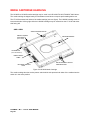
MEDIA CARTRIDGE HANDLING
SETTING THE WRITE PROTECTION SWITCH
AFFIXING LABELS
MEDIA INSERTION AND REMOVAL
CARTRIDGE INSERTION
CARTRIDGE REMOVAL
MANUAL CARTRIDGE RELEASE MECHANISM
OPENING THE BASEPLATES
RETRACTING THE CARTRIDGE
MEDIA LOADING
OPERATOR MAINTENANCE
INSPECTING AND CLEANING FAN AND BLOWER FILTERS
REPLACING FUSES
MEDIA CLEANING
MEDIA CLEANING USING CLEANING KIT P/N 97662550
APPENDIX A
GERMAN TRANSLATIONS/ÜBERSETZUNGEN INS DEUTSCHE
39
39
40
41
41
43
58
63
65
66
68
69
70
71
72
73
73
74
75
77
77
78
80
80
81
81
SCOPE
This User Manual describes unpacking, installing, operating, and maintaining the Plasmon LF 8120 Auto
Loader High-Performance Optical Disk Drive.
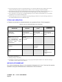
RELATED PUBLICATIONS
Publication
Part Number
LD 8100/LF 8120/LF 8600/LF 8602 Product Specification
97663035
LD 8100/LF 8120/LF 8600/ LF 8602 SCSI Interface Specification
97662164
LF 8120 Hardware Maintenance Manual
97664107
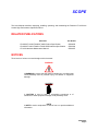
NOTICES
Three levels of notices are used throughout this document.
WARNING
A WARNING is used to alert the reader of situations or conditions that
could potentially result in personal injury, fire hazard or equipment
damage.
CAUTION
A CAUTION is used to warn of undesirable procedures or of
situations in which equipment damage could potentially result.
NOTE
A NOTE is used to emphasize an area of text or to provide additional
information.
97664106 A
Page 9
WARRANTY STATEMENT
The LF 8120 is warranted as stated in the purchase agreement between Plasmon and it’s customer,
or the Plasmon sales order acknowledgment, whichever is applicable.
The Plasmon LMS quality system is in compliance and registered to ISO 9001. The LF 8120 is
manufactured from new parts, or remanufactured parts.
LF 8120 warranty does not cover defects or damage caused by the use of unauthorized parts or
repairs or improper use or maintenance. Repairs or replacements not covered by the warranty will
be invoiced at LMS’ then current prices.
The warranty is void when installation, service or repairs are performed by unauthorized
personnel; when the product is affected by unauthorized alterations, modifications or other
tampering or misuse; when the product is incorporated into a system which causes or involves
any changes in the physical, mechanical or electrical arrangement of the product; or when the
product is not used in accordance with its applicable specifications.
The term, authorized personnel, is defined as those persons who have been trained by Plasmon
LMS Technical Services.
PLASMON L M S - LF 8120 USER MANUAL
Page 10
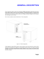
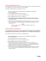
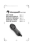
GENERAL DESCRIPTION
The LF 8120 Auto Loader is a write once read many (WORM), high-capacity optical disk drive with an
integral shuttle capable of holding up to twelve LM 8000, or LM 6000 media cartridges. The integral shuttle
moves laterally to position one of twelve media cartridges for automated loading and unloading into the
optical drive. The LF 8120 Auto Loader provides up to 30 GBytes (LM 8000 Cartridge) of online storage or
up to 360 GBytes nearline storage.
The LF 8120 is available in either a Rack Mount or Tower configuration.
RACK MOUNT
CONFIGURATION
TOWER
CONFIGURATION
Figure 1. LF 8120 Configurations
A Drive Operator Console (DOC) located on the front panel of the drive provides user control of drive
operation and configuration as explained in the Operating Instruction section of this manual. Operating
messages are presented on the alphanumeric display in English, French or German. The language used is
selectable. The front panel includes a lockable media access door to provide operator access to the shuttle
and media cartridges.
97664106 A
Page 11
The Auxiliary Diagnostic Port (ADP), located on the rear panel of each drive, can be used to download
updates to the drive firmware in the field. Refer to the LD 8100/LF 8120/LF 8600/LF 8602 Product
Specification (P/N 97663035) for more information.
The LD 8120 supports a maximum sustained read and write transfer rate of 6.0 MBytes/sec without data
verification. The drive will also support a 2.9 MBytes/sec write transfer rate with error correction and defect
management to maintain data integrity and manage media flaws.
The LF 8120 implements the Small Computer System Interface (SCSI) via standard SCSI-2 microconnectors located on the rear panel. Single-ended and differential interface options are available, and the
interface can be changed in the field. Both the single-ended and differential controllers support
asynchronous or synchronous data transfer operations.
Preventive maintenance for the LF 8120 is minimal (refer to Operator Maintenance section of this manual).
Corrective maintenance is simplified by internal diagnostic firmware which detects, isolates and reports
malfunctions to the operator and identifies the Field Replaceable Unit (FRU).
LM 8000 media is interchangeable between the LD 8100, LF 8120, LF 8600, and the LF 8602. The
LF 8120 can also read LM 6000 and LM 4000 media. Contact Plasmon LMS for availability and ordering
information for the LM 4000 media option.
PLASMON L M S - LF 8120 USER MANUAL
Page 12
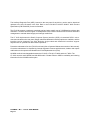
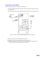
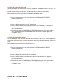
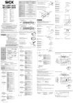
DRIVE CHARACTERISTICS
The LF 8120 Rack Mount and Tower configurations use the same major assemblies (refer to the next two
figures).
75.75 CM
(29.75 IN)
45.10 CN
(17.75 IN)
2.54 CM
(1.0 IN )
LF 8120 RACK MOUNT
CONFIGURATION
45.10 CN
(17.75 IN)
45.10 CN
(17.75 IN)
75.75 CM
(29.75 IN)
LF 8120 TOWER
CONFIGURATION
58.42 CM
(23.0 IN)
Figure 2. LF 8120 Dimensional Details
97664106 A
Page 13
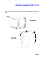
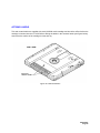
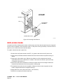
FRONT PANEL
The LF 8120 front panel (see figure on the
right) includes a Drive Operator Console
(DOC), media access door, and door lock
within a bezel assembly. Refer to the
Operating Instruction section of this
manual for a detailed description of the
DOC.
DOC
BEZEL
MEDIA
ACCESS
DOOR
KEY LOCK
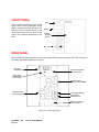
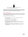
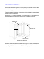
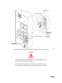
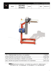
REAR PANEL
The LF 8120 rear panel contains the power switch along with AC power connector and fuses, the ground
connector, and external interface connectors.
SCSI-2 I/O
CONNECTORS
MANUAL RELEASE
ACCESS HOLE
AUXILLIARY
DIAGNOSTIC
PORT (ADP)
BLOWER GRILL
AND FILTER ELEMENT
FAN GRILL AND
FILTER ELEMENT
AC POWER SWITCH
AC POWER
RECEPTACLE
MANUAL RELEASE
ACCESS HOLE
Figure 3. LF 8120 Rear Panel
PLASMON L M S - LF 8120 USER MANUAL
Page 14
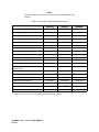
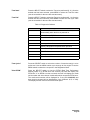
DIMENSIONS AND WEIGHT
The table below lists the reference dimensions of the LF 8120 configurations.
Table 1. Dimensions of the LF 8120 Configurations
DIMENTION
RACK MOUNT
TOWER
Length
75.57 CM (29.75 IN)
75.57 CM (29.75 IN)
Width
45.10 CM (17.75 IN)
45.10 CM (17.75 IN)
Height
47.0 CM (18.5 IN)
58.42 CM (23.0 IN)
SHIPPING WEIGHT
The LF 8120 shipping weight is listed below. These values do not include media cartridges.
Rack Mount: 71.21 kg (157 lbs)
Tower: 75.75 kg (167 lbs)
The weight of one LM 8000 cartridge is approximately 1.18 kg (2.6 lbs).
97664106 A
Page 15
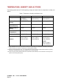
TEMPERATURE, HUMIDITY AND ALTITUDE
The following table lists the LF 8120 operating, storage and transit limits for temperature, humidity and
altitude.
Table 2. Temperature, Humidity and Altitude Limits
CONDITION
OPERATING
NONOPERATING
STORAGE/TRANSIT1
Temperature
10° to 42° C 2
(50° to 108° F)
-40° to 66° C
(-40° to 151° F)
-40° to 66° C
(-40° to 151° F)
Maximum Rate of
Change
11° C/hr (20° F/hr)
20° C/hr (36° F/hr)
20° C/hr (36° F/hr)
Humidity
(Noncondensing
10 to 90%
5 to 95%
5 to 95%
Maximum Rate of
Change
10%/hr
10%/hr
10%/hr
Maximum Wet Bulb
Temperature 3
28° C (82° F)
46° C (115° F)
46° C (115° F)
Minimum Dew Point
2° C (35.6° F)
2° C (35.6° F)
2° C (35.6° F)
Altitude
-300 to 3,000 m
(-984 to 9,840 ft)
-300 to 3,000 m
(-984 to 9840 ft)
Storage:
-300 to 3,000 m
(-984 to 9,840 ft)
Transit:
-300 to 12,000 m
(-984 to 40,000 ft)
1 Storage specifications are for 90 days maximum in Plasmon LMS packaging. No condensation is permitted. Transit specifications are based on a maximum 1-week period in a factory-sealed container.
2 Maximum operating temperature is 42 _C for a free-standing drive at sea level unless otherwise stated. Maximum operating
temperature is derated linearly above 300 m altitude to 38 _C at 2,000 m altitude.
3 See the LD 8100/LF 8120/LF 8600/LF 8602 Product Specification (P/N 97663035) for more information concerning the temperature and humidity operating range.
PLASMON L M S - LF 8120 USER MANUAL
Page 16
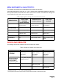
MEDIA ENVIRONMENTAL CHARACTERISTICS
The following table presents the LM 8000 Media environmental characteristics.
If the media temperature is more than 10° C (50° F) different from the ambient temperature of the Drive,
then the media should be acclimated in the Drive environment for at least 30 minutes before writing to the
media. Reading from the media may be done immediately.
Table 3. Media Operation, Storage and Transportation Environments
SPECIFICATION
OPERATION AND
SHORT TERM
STORAGE
(2 years maximum)
TRANSPORTATION
(2 weeks maximum)
LONG TERM
STORAGE
Temperature
10°C to 47°C
(50°F to 116.6°F)
-20°C to +55°C
(-4.0°F to 131.0°F)
10°C to 30°C
(50°F to 86.0°F)
Relative Humidity
(no condensation)
5% - 80%
5% - 90%
5% - 80%
Wet Bulb Temperature
26°C max. (78.8°F)
26°C max. (78.8°F)
26°C max. (78.8°F)
Temperature Gradient
10°C/hr max.
(18.0°F/hr max.)
31°C/hr max.
(55.8°F/hr max.)
5°C/hr max.
(9.0°F/hr max.)
Air Pressure
N/A
N/A
N/A
Solar Radiation
N/A
Case to be kept closed
Not to be stored in direct
sunlight
SHOCK AND VIBRATION
The following table lists the conditions and limits for shock and vibration.
Table 4. Shock and Vibration Criteria and Limits
CONDITION
OPERATING
Swept Vibration
(Bidirectional)
1 Octave/Min
5 to 250 Hz 0.1 g Peak,
250 to 500 Hz
0.25 g Peak
Shock 3
(Host Retries May Be
Required and Drive
Performance May
Degrade During Test
10 - msec Half Sine Pulse
of 2.5 g Peak, with pulses
applied every 3 sec
Unpacked (3 Axis)
STORAGE/TRANSIT2
5 to 44 Hz, 0.03 in
Double Amplitude,
44 to 500 Hz
3.0 g Peak
5 - msec Half Sine
Pulse of 20 g Peak
Packed on Pallet
1 With media removed.
NONOPERATING1
5 to 44 Hz, 0.03 in
Double Amplitude,
44 to 500 Hz
3.0 g Peak
46 - cm (18 - in)
Drop Test Flat
2 In LMS - approved packaging.
3 Shock repetition rate should be limited to allow mechanical system transients to subside between pulses.
97664106 A
Page 17
AC POWER REQUIREMENTS
The LF 8120 has a grounded power connector integrated into the AC power switch. Over current
protection is provided by two fuses integrated into the AC power switch. Two spare fuses are included
within the power connector. Refer to the Operator Maintenance section for the fuse replacement
procedure.
The drive's power supply accepts the input line voltages listed in the table below. The power supply is auto
ranging and does not require mechanical switching for input voltage or frequency selection.
Table 5. AC Power Requirements
READY
SURGE PEAK
<1s
(SPIN-UP)
READY + 1 SPINUP/DN
CYCLE EVERY
10 s
MIN SERVICE
RATING
95.0V TO 128V
1.4A / 110W
10A
2.0A / 160W (1)
15A
173.0 TO 268V
0.7 / 110W
5A
1.0A / 160W
15A
AC LINE
VOLTAGE
1
This current measurement determines the stated power and maximum heat dissipation of the Drive (546 BTU/hr) based on RMS
current over the 10S cycle derated by the Power Factor. It also determines the 2.0 A UL plate rating.
NOTE
After the power has been turned off, the operator must wait 1 second
before turning on the power again
AC GROUND
The LF 8120 chassis should be connected to earth ground for operator safety. The AC power cord has a
grounding conductor which connects the LF 8120 chassis to safety ground through the site AC power
system. If the site AC system ties its ground wire connection to earth ground, then the LF 8120 chassis will
also be tied to earth ground. All site AC power connections must be maintained on the same safety
ground.
A line grounding connector located on the rear panel can also be used to tie the LF 8120 chassis to earth
ground. This ground connector is a 6-mm (0.24-in.) M4 with a nut and lock washer.
AC POWER CORD
The type of AC power cord supplied with the LF 8120 will depend upon the configuration ordered.
POWER SUPPLY PROTECTION FEATURES
The LF 8120 power supply provides over and under voltage protection, over current protection, power
failure detection and over temperature protection. Should an out-of-range condition be detected, the
LF 8120 will shut down the DC outputs of the power supply. After the situation is corrected, power can be
restored by turning the AC power switch to the off position and then to the on position again.
PLASMON L M S - LF 8120 USER MANUAL
Page 18
TILT RANGE
The LF 8120 is not designed for use when tilted from the vertical position.
HEAT DISSIPATION
The drive will typically present a heat load of 95 kg-calories/hr (376 BTU/hr) during a read/write operation.
When media cartridges are inserted, loaded, spun up, spun down, unloaded and removed at the drive's
maximum rate, the LF 8120 will typically present a heat load of 138 kg-calories/hr (546 BTU/hr).
PARTICULATE LIMITS
The LF 8120 is designed for use in an office or computer room. The environment must have a low dust
level. The LF 8120 filters incoming air for cooling to reduce the quantity of particles entering the drive;
however, the filter is not effective against small particles (including tobacco smoke) which will become
deposited on optical components and media, causing degradation in drive performance. Refer to the
Operator Maintenance section for media cleaning and air filter cleaning instructions.
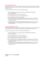
WARNING LABELS
The LF 8120 is classified as a laser product and meets all United States federal requirements. The warning
labels shown in the figure below have been applied to the Drive to ensure compliance with federal
regulations and must not be removed from the LF 8120.
LASER DANGER
LABEL
LASER CLASS
LABEL
CANADIAN
CLASS A LABEL
FCC, RFI,
CLASS A LABEL
Figure 4. Location of LF 8120 Warning Labels
97664106 A
Page 19
PLASMON L M S - LF 8120 USER MANUAL
Page 20
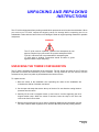
UNPACKING AND REPACKING
INSTRUCTIONS
The LF 8120 is shipped with foam packing material which protects the unit from shock and vibration. When
you receive your LF 8120, inspect the shipping carton for damage before unpacking the unit to
substantiate a claim with the carrier if the unit is damaged. Retain all original packing materials for possible
reshipment.
WARNING
The LF 8120 must be unpacked, repacked and transported by two
persons. Physical injury can result if one person attempts to lift the
LF 8120. A wheeled cart is recommended for transporting the
LF 8120 within a building. Precautions should be taken to guard
against sudden bumps and jarring.
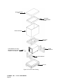
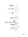
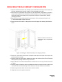
UNPACKING THE TOWER CONFIGURATION
The LF 8120 is packaged as illustrated in the next figure. The top, bottom and sides of the LF 8120 are
protected from shock and vibration by foam cushions. The top cushions are also used to hold the
accessories box (inner box) which is placed between the blocks of foam.
To unpack the unit:
1. Move the carton to the installation site. Unpacking the carton at the installation site
minimizes the effects of vibration and shock.
2. Cut the tape and straps that secure the top of the box. Do not allow the cutting blade to
penetrate into the carton.
3. Carefully lift the outer corrugated carton up and remove it while supporting the inner
hinged wooden ramp. When the carton is removed, lower the ramp to the floor and
remove the front foam cushion.
4. Remove the accessories box (inner carton) containing cables and documentation and the
two foam cushions which support the box. Remove the ESD protective packing material.
97664106 A
Page 21
OUTER CARTON
LID
OPTIONS/
ACCESSORIES
TRAY
OUTER CARTON
TOP FOAM
CUSION
FOAM
CUSHION
FOAM INSERT LOCATED
BETWEEN SHUTTLE AND
FRAME OF THE DRIVE
FOAM CUSHION
PALLET
Figure 5. LF 8120 Tower Packing
PLASMON L M S - LF 8120 USER MANUAL
Page 22
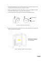
5. Ensure that the casters are locked. Lift the front end of the LF 8120 high enough to remove
the pallet cushion and then lower the LF 8120 onto its casters.
6. Unlock the casters and roll the LF 8120 down the ramp to its installation location.
Precautions should be taken to avoid sudden bumps and jarring.
7. Lock the casters once you have the LF 8120 situated at its installation location.
UNLOCKED
LOCKED
Figure 6. Caster for the LF 8120 Tower
8. Open the media access door and remove the foam insert. Manually move shuttle all the
way to the right to the home position.
MANUALLY MOVE SHUTTLE
TO THE RIGHT TO REMOVE
THE FOAM INSERT
Figure 7. Moving the Shuttle to the Home Position
97664106 A
Page 23
UNPACKING THE RACK MOUNT CONFIGURATION
To unpack the LF 8120 Rack Mount configuration, refer to the next figure and perform the following
procedure:
1) Move the carton to the installation site. Unpacking the carton at the installation site
minimizes the effects of vibration and shock.
2. Cut the tape that secures the top of the box. Do not allow the cutting blade to penetrate
into the carton.
3. Carefully lift the outer corrugated carton up and remove it.
4. Remove the accessories box (inner carton) containing cables and documentation, and
remove the ESD protective packing material.
5. Remove the two cushions which support the accessories box (inner carton).
6. Carefully lift and remove the LF 8120 from the shipping carton and place it on a flat surface
capable of supporting 48 kg (106 lbs). A wheeled cart is recommended for transporting
the LF 8120 within a building. Precautions should be taken to avoid sudden bumps and
jarring.
CAUTION
The bezel is slightly larger than the chassis. When placing the drive
onto a flat surface, allow the front end of the LF 8120 to extend over
the edge of the supporting surface so that the bezel does not bear any
weight.
7. Open the media access door and remove the foam insert. Manually move the shuttle all
the way to the right to the home shuttle position.
PLASMON L M S - LF 8120 USER MANUAL
Page 24
OUTER CARTON
LID
OPTION/
ACCESSORIES
TRAY
OUTER CARTON
FOAM
CUSHION
FOAM INSERT LOCATED
BETWEEN SHUTTLE AND
DRIVE FRAME
FOAM
CUSHION
PALLET
Figure 8. LF 8120 Rack Mount Packing
97664106 A
Page 25
INSPECTING THE LF 8120
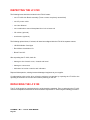
The following items should be included in the LF 8120 carton:
•
one LF 8120 with Bezel assembly (Tower comes completely assembled)
•
one AC power cable
•
one User Manual
•
one combination manual baseplate/door lock release tool
•
I/O cables (optional)
•
terminators (optional)
The following optional items, if ordered, will have been shipped with the LF 8120 in separate cartons:
•
LM 8000 Media Cartridges
•
Rack Mount Installation Kit
•
Blank Panel Kit
After unpacking the LF 8120, check for:
•
damage to the chassis cover, chassis and bezel
•
damage to connectors
•
dislocated or broken controls and indicators
Report all discrepancies, missing items and damaged equipment to your supplier.
If condensation exists on the drive, allow the moisture to evaporate by exposing the LF 8120 to the
operating environment for at least 6 hours before powering on the unit.
REPACKING THE LF 8120
The LF 8120 should be repacked using the original packing materials. Prior to packaging the LF 8120,
close the baseplates as described in the next section. Repack the LF 8120 using the following procedure.
PLASMON L M S - LF 8120 USER MANUAL
Page 26
CAUTION
Shipping the LF 8120 without closing the baseplates may result in
damage to the drive which is not covered under warranty.
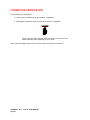
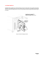
CLOSING THE BASEPLATES
1. Ensure that a cartridge is not inserted in the drive; if it is, unload the cartridge. Remove all
cartridges from the shuttle. To remove cartridges from a drive that is not operational, follow
the procedure below:
2. Ensure that the AC Power switch is set to the OFF ( O ) position.
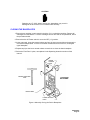
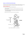
3. At the rear panel, insert the manual release tool into the upper access hole and engage the
recessed D-shaped shaft. Turn the tool handle clockwise as far as it will turn, closing the
upper baseplate.
4. Repeat step b) at the lower manual release access hole to close the lower baseplate.
5. Select the "Park Drive" option, as explained in the Operating Instruction section of this
manual.
UPPER
ACCESS
HOLE
MANUAL RELEASE
TOOL
LF 8120 SKIN
NOT SHOWN
REAR PANEL
LOWER ACCESS
HOLE
Figure 9. Manually Closing the Drive's Baseplates
97664106 A
Page 27
REPACKING THE TOWER CONFIGURATION
1. Open the media access door.
2. Manually push the shuttle all the way to the left and insert the foam shipping block to hold it in
place. Close the media access door.
3. Roll the LF 8120 up onto its shipping pallet and lock all four casters to prevent rolling.
4. Lift the front and rear of the LF 8120 high enough and place the caster support underneath the
drive.
5. Raise the wooden ramp to the vertical position and place the pallet cushion between the ramp
and the front panel of the LF 8120. Place the ESD protective packing material on top of the
drive.
6. Place the two end cushions which hold the accessories box on the top front and rear of the LF
8120.
7. Place the power and interface cables, User Manual and other accessories into the options and
accessories box and seal with tape. Place this box between the top end cushions.
8. Slip the corrugated shipping carton over the LF 8120 and the raised ramp, and lower the
carton down to the top of the pallet.
9. Strap the carton to the pallet at each end.
PLASMON L M S - LF 8120 USER MANUAL
Page 28
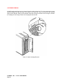
REPACKING THE RACK MOUNT CONFIGURATION
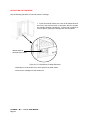
1. Open the media access door and manually move the shuttle all the way to the left and insert
the foam shipping block to hold it in place. Close the media access door.
2. Remove the LF 8120 chassis with its bezel from the Rack Mount configuration by reversing
the procedure detailed in the Installation and De-installation section. The bezel extends
below the chassis; ensure that you do not place the unit flat on a hard surface, thereby
damaging the bezel.
3. Ensure that the lower packing material is positioned to form a rectangular frame for the
LF 8120 chassis which opens to the front.
4. Place the bezel relief cushion on the pallet so that it will support the chassis just behind the
bezel.
MANUALLY MOVE THE SHUTTLE
TO THE LEFT INTO THE SHIPPNG
POSITION
Figure 10. Moving the Shuttle Assembly to the Shipping Position
5. Place the LF 8120 into the foam frame so that the drive rests on the bezel relief cushion and
the bezel bears no weight.
6. Place the lower front foam cushion between the carton and the front of the LF 8120. Place the
ESD protective packing material on top of the drive.
7. Position the two end cushions which hold the accessories box on the top front and rear of the
LF 8120.
8. Place the power and interface cables, User Manual and other accessories into the options and
accessories box and seal with tape. Place this box in between the foam end cushions.
9. Lower the upper sleeve down onto the lower carton and pallet.
10. Strap the carton to the pallet at each end.
97664106 A
Page 29
PLASMON L M S - LF 8120 USER MANUAL
Page 30
INSTALLATION AND
DE-INSTALLATION
INSTALLATION REQUIREMENTS
Adequate clearances must be provided around the LF 8120 during installation to prevent crimping and
bending of cables and to ensure that future servicing can be performed safely. These clearances are also
required to properly ventilate the LF 8120 and to provide operator access to the DOC and to the media
access door for loading and unloading media.
CAUTION
When the LF 8120 is mounted in an equipment rack or cabinet,
ensure that the internal temperature within the rack or cabinet does
not exceed the operating limits as stated in the Product Specification
and this document. When vertically stacked, these units require
special attention at the top area where higher temperatures exist.
The LF 8120 must be connected to a power distribution system that
has a direct connection to earth ground (Terminated Terra [ TT ]
network/ground connected). This unit is not suitable for use on a
floating ground (Interrupted Terra [ IT ] network).
Ensure the drive is connected to a power distribution system with
adequate current-handling capacity.
The following table lists the clearances required to provide proper cooling air circulation, adequate access
for cartridge loading and unloading, and full rack extension.
Table 6. Operational Clearances for LF 8120 Configurations
AREA
RACK MOUNT
TOWER
Front
132 cm (52 in)
51 cm (20 in)
Rear
51 cm (20 in)
51 cm (20 in)
Sides
12.7 cm (5 in)
97664106 A
Page 31
Ensure that the site selected for the LF 8120 Tower or Rack Mount configuration is able to support a
volumetric air flow of 0.77 m3/min. (27 cfm). For the Rack Mount configuration, the back door of the
enclosing equipment cabinet must have air vents. Ensure that the operating environment is free from dust.
WARNING
To prevent fire or shock hazard, do not expose the LF 8120 to rain or
moisture. Refer servicing to qualified technicians.
In case of fire or other emergency, isolate the units from the main
power by disconnecting the power plugs from their site power
receptacles. In situations where disconnecting the plugs is not
possible or practical, disconnect the system main power to isolate the
units from the main power. Use of controls or adjustments, or
performance of procedures other than those specified herein may
result in exposure to hazardous laser radiation.
Do not stare directly into the laser beam or its reflection on any
reflecting mirror-like surface. Invisible laser radiation can be emitted if
the unit is open and safety interlocks are defeated.
TOWER INSTALLATION
The LF 8120 Tower configuration is shipped as a complete assembly, ready for cable connections and
power up. No tools are required for the installation.
CAUTION
Remove the foam shipping block from the shuttle assembly before
powering on the LF 8120.
To install the Tower configuration:
1. Connect the AC power cord as explained in the Connecting the Power Cord section. (Refer to
the Installation and De-installation section for information regarding the AC ground.)
2. Connect the host interface SCSI cables and appropriate signal terminators, if required, as
explained in the Installation and de-installation section.
PLASMON L M S - LF 8120 USER MANUAL
Page 32
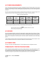
SCSI BUS CONSIDERATIONS
The length of the SCSI interface cables used to interconnect the LF 8120 with other SCSI devices is
dictated by the type of SCSI controller installed in each LF 8120. A maximum of seven LF 8120's can be
connected to a host computer in a daisy chained configuration using the appropriate SCSI controller and
cable options.
When the single-ended interface controller is used on all SCSI devices, the total length of the SCSI
interface cable cannot exceed 6 m (19.5 ft). (Plasmon LMS does not recommend single-ended fast
synchronous.) When a differential interface controller is used on all SCSI devices, the total SCSI interface
cable length cannot exceed 25 m (82 ft).
NOTE
The internal SCSI cable for each LF 8120 is approximately 22.86 mm
(9.0 in.). This distance must be considered as part of the total SCSI
cable length.
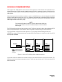
The SCSI interface cabling used to interconnect an LF 8120 to a host can be daisy chained between SCSI
devices as illustrated below. One interface cable is required to interface each pair of SCSI devices.
Any Single Ended configured Drive that is placed on a Low Voltage Differential/Single Ended bus
(LVD/SE) bus must be terminated using a standard SCSI SE terminator on at least one end of the SCSI
bus for proper operation.
LF 8120
HOST
HOST SCSI
CONNECTOR
SCSI
CONNECTORS
LF 8120
SCSI
CONNECTORS
LF 8120
SCSI
CONNECTORS
TERMINATOR
NOTE: The SCSI bus must also be
terminated at the host. Normally, the
termination function is built into the
host adapter.
8K/SCSI_DAISY.vsd
Figure 11. Host-to-LF 8120 Daisy Chain Cable Connections
A terminator must be installed on the vacant connector of the last SCSI device in the SCSI bus chain. The
SCSI bus must be terminated externally on the LF 8120 rear panel when an LF 8120 is the last SCSI
device on the bus.
97664106 A
Page 33
NOTE
You must first determine the type of termination your host system
requires.
In a daisy chain configuration, a terminator must be used on both the first and last devices on the bus.
One of these devices may be the host adapter. All other LF 8120's between the first and last device in the
daisy chain should not be terminated.
NOTE
Installation of both an active single-ended terminator and a passive
single-ended terminator on the same bus is not recommended.
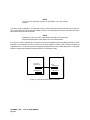
If only one LF 8120 is attached to a host, the bus must be terminated at the host adapter and the LF 8120.
Normally, the termination function is built into the host adapter. Power for the external terminator is
supplied by the LF 8120 and may also be supplied by another device in the SCSI daisy chain. Terminator
power for external terminators is provided by the LF 8120 power supply.
HOST
LD 8120
HOST SCSI
CONNECTOR
TERMINATOR
SCSI
CONNECTORS
TERMINATOR
Figure 12. LF 8120-to-Host Cable Connection
PLASMON L M S - LF 8120 USER MANUAL
Page 34
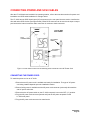
CONNECTING POWER AND SCSI CABLES
After the LF 8120 has been installed in its operating location, refer to the next three sections for power cord
installation and SCSI cable installation for a single device.
The LF 8120 has two SCSI input/output (I/O) connectors on the rear panel that are used to interface the
drive with other SCSI devices (see figure below). Either SCSI connector can be used as the input or output
port because the internal controller cable connection is common to both connectors.
LF 8120 SKIN
NOT SHOWN
SCSI
CONNECTORS
AC POWER
CABLE
AC POWER
SWITCH
Figure 13. Rear Panel of the LF 8120 Showing SCSI Connectors and AC Power Cord
CONNECTING THE POWER CORD
To install the power cord on an LF 8120:
1. Ensure that an AC power cord is available and ready for installation. The type of AC power
cord being installed depends upon the installation location.
2. Ensure facility power is available and the AC power cord connector (male end) will match the
site AC power wall outlet.
3. Ensure that the AC power switch on the LF 8120 rear panel is set to the OFF ( O ) position.
4. Plug the AC power cord connector (female end) into the AC power receptacle on the
LF 8120 rear panel.
5. Plug the AC power cord connector into a wall outlet.
97664106 A
Page 35
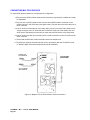
CONNECTING MULTIPLE DEVICES
To install SCSI interface cables for a multiple-device configuration:
1. Ensure that the SCSI interface cables and a terminator (if required) are available and ready
for installation.
2. Plug one end of a SCSI interface cable into the vacant SCSI interface connector on the
previous device in the SCSI chain (see figure below). Plug the other end of the cable into a
SCSI connector.
3. If the LF 8120 is not the last unit in the daisy chain, plug one end of the other cable into the
vacant connector on the LF 8120 and then connect the other end of the cable to the next
SCSI device. Repeat this process until you reach the last SCSI device in the daisy chain.
4. If the LF 8120 is the last unit in the daisy chain, install a terminator on the LF 8120's vacant
SCSI connector.
5. Ensure that the SCSI bus is also terminated at the host adapter end.
6. The SCSI bus must be terminated at both ends in accordance with the LD 8100/LF 8120/
LF 8600/LF 8602 SCSI Interface Specification (P/N 97662164).
FROM LAST
SCSI DEVICE
LF 8120 SKIN
NOT SHOWN
OUT TO NEXT
SCSI DEVICE
Figure 14. Multiple LF 8120 SCSI Interface Cable Connections
PLASMON L M S - LF 8120 USER MANUAL
Page 36
CONNECTING A SINGLE DEVICE
To install a SCSI interface cable for a single-device configuration:
1. Plug one end of the SCSI interface cable into the vacant SCSI interface connector on the host
(see figure below).
2. Plug the other end of the interface cable into a SCSI I/O connector on the LF 8120 rear panel.
INPUT FROM
HOST
LF 8120 SKIN
NOT SHOWN
TERMINATOR
Figure 15. Single LF 8120 SCSI Interface Cable and Terminator Connection
3. Install a terminator on the vacant connector of the LF 8120.
4. Ensure that the SCSI bus is also terminated at the host adapter end.
5. The SCSI bus must be terminated at both ends in accordance with the LD 8100/LF 8120/
LF 8600/LF 8602 SCSI Interface Specification (P/N 97662164).
97664106 A
Page 37
CONNECTOR VERIFICATION
Prior to powering on the system:
1) Verify proper termination at the host adapter, if applicable.
2. Verify proper termination at the last LF 8120 on the bus, if applicable.
CAUTION
Ensure that the foam shipping block has been removed from the
shuttle assembly before powering on the LF 8120.
Refer to the Operating Instruction section in this manual for power-on procedures.
PLASMON L M S - LF 8120 USER MANUAL
Page 38
OPERATING INSTRUCTIONS
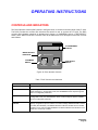
CONTROLS AND INDICATORS
The Drive Operator Console (DOC) shown in the figure below, is located on the front panel of the LF 8120.
The DOC provides the controls and indicators that enable a user to operate the LF 8120. The DOC
controls and indicators consist of an alphanumeric display, a LOAD/MENU switch, a TEST/SELECT
switch, and a WRITE PROTECT indicator. Refer to the table below for a description of the DOC controls
and indicator.
ALPHANUMERIC
DISPLAY
WRITE PROTECT
INDICATOR
WRITE PROTECT
LOAD/MENU
SWITCH
TEST/SELECT
SWITCH
LOAD/MENU
TEST/SELECT
Figure 16. Drive Operator Console
Table 7. DOC Controls and Indicators
CONTROL/INDICATOR
Alphanumeric Display
PURPOSE/FUNCTION
Displays operating, configuration and test status messages
LOAD/MENU Switch
In operating mode, the LOAD/MENU switch controls the loading and unloading of
media cartridges. In Configuration mode, the LOAD/MENU switch steps through the
menu of configurable parameters.
TEST/SELECT Switch
In operating mode, the TEST/SELECT switch invokes the diagnostic self-test. In
Configuration mode, the TEST/SELECT switch scrolls through the options available
for each configurable parameter.
WRITE PROTECT
Indicator
The WRITE PROTECT indicator illuminates when either the Write Protect (WRT
PROT) configuration option is enabled or a media cartridge WRITE PROTECT switch
is locked (write disabled). The WRITE PROTECT indicator will flash when an RTPM
condition occurs. Also, the WRITE PROTECT indicator will flash when the drive or the
media is in a read only condition.
97664106 A
Page 39
POWER-ON PROCEDURE
The LF 8120 is powered on with the AC Power Switch located on the rear panel. The ON position is
indicated by a ( I ) and the OFF position is indicated by a ( O ) as illustrated below.
LF 8120 SKIN
NOT SHOWN
AC POWER OFF (O)
AC POWER ON (I)
Figure 17. LF 8120 AC Power Switch Positions
Perform the following procedure to power on the LF 8120:
1. Ensure that the LF 8120 is properly connected (see SCSI Bus Considerations sections).
2. Refer to the Media Insertion and Removal section and insert a cartridge into slot 1. If slot 1 is
empty, the LF 8120 will display "1 Empty" on the DOC shortly after initial power on.
NOTE
Slot 1 is the factory setting for the media autoload configuration
option.
If this option has been changed by the user, all references to slot 1 in
this manual apply instead to the slot number selected in the autoload
configuration option.
Refer to the Configuration Mode section for more information on
setting configuration options.
PLASMON L M S - LF 8120 USER MANUAL
Page 40
3. Set the AC Power Switch to the ON ( I ) position and verify that air is flowing through the
LF 8120.
4. Verify that the WRITE PROTECT indicator is illuminated briefly.
5. Verify that the "Selftest" message is displayed on the DOC.
The "Selftest" message indicates that the power-on selftests are running. When the power-on selftests
have run without errors, the drive will perform a test to determine which slots in the shuttle are occupied by
media cartridges and then will load media number 1.
When the "1 Ready" message is displayed, the LF 8120 has passed the power-on selftests and has
successfully loaded the LM 8000 media cartridge in slot 1.
6. Verify that the "Selftest" message displayed on the DOC is replaced by the "1 Ready"
message.
7. Refer to the Modes of Operation section of this manual to familiarize yourself with the
LF 8120 modes of operation.
The LF 8120 is now in the normal Operating mode, and is ready to be controlled and accessed by a host
system.
MODES OF OPERATION
The LF 8120 has three modes of operation that are selectable from the DOC:
•
Operating Mode
•
Configuration Mode
•
Test Mode
In Operating mode the host system can read and write data, and select and load media cartridges. In
Configuration mode an operator can view a menu of parameters and select options for each parameter.
Test mode invokes drive diagnostics to verify proper drive operation.
OPERATING MODE
The LF 8120 enters the Operating mode after being powered on and displays the "# Ready" message on
the DOC. The DOC will display the appropriate messages listed in the next table during normal operation.
To enter Operating mode if the drive is in Test mode, wait until the tests are completed and then press the
LOAD/MENU switch. To enter Operating mode if the drive is in Configuration mode, press the LOAD/
MENU and the TEST/SELECT switches simultaneously.
97664106 A
Page 41
NOTE
The pound symbol #, shown in the table below, designates the slot
number.
Table 8. LF 8120 DOC Operating Mode Messages
DOC DISPLAY
(ENGLISH)
DOC DISPLAY
(FRENCH)
DOC DISPLAY
(GERMAN)
Inserting Cartridge #
Inserting #
Insere#
Einfügend
Loading Media #
Loading #
Charger #
Ladend #
Drive Ready (Cartridge # not Locked(1)
# Ready
# Prêt
# Bereit
Drive Ready (Cartridge # Locked1
Locked
Verrouillé
Gesperrt
Reading #
Lecture #
Lesend #
Writing #
Eriture #
Schreibend #
Unload Cartridge #
Unloding #
Decharge #
Entladend #
Removing Cartridge
Removing #
Retir Disk #
Entfernend #
Moving to Cartridge #
Moving to #
Deplace #
Gehe Zu #
Cartridge # Positioned
# Positioned
Positione #
# In Pos
Home
Origine
Ruheposition
SCSI reset
SCSI Reinit
SCSI Reinit
Illegal Request (Spindown Disabled/
Door Locked)
Denied
Refuse
Abgelehnt
Drive is Testing Itself
Selftest
Autotest
Selbsttest
Drive is Scanning Media #
Scanning #
Scanning #
Media Prüf #
Insert Cartridge #
# Inserted
# Insere
# Eingelert
Shuttle is being Initialized
Init Shuttle
Init Shuttle
Shuttle Init
Slot # in Shuttle is Empty
# Empty
# Vide
# Leer
Door Open
Porte Ouvert
Türe Offen
Move to Home
Depl Origine
Zur Ruhepos
OPERATING CONDITION
Drive Reading Cartridge #
Drive Writing Cartridge #
Shuttle in Home Position
Drive is in Rest
Door is Open
Shuttle Moving to Home Position
1 "Locked" means that the host has issued a PREVENT MEDIA REMOVAL command.
PLASMON L M S - LF 8120 USER MANUAL
Page 42
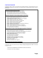
CONFIGURATION MODE
Configuration mode is used to view and set drive operating parameters. The parameters that can be
configured and displayed are summarized in the following (the corresponding DOC display is shown in
parentheses).
Viewing the configuration ("View Config")
View the current operating parameters ("View Current")
View the firmware revisions of the drive ("View FW Revs")
View the hardware revisions of the drive ("View HW S/Ns")
View the hardware part numbers of the drive ("View HW P/Ns")
Setting the configuration of the operating parameters ("Set Config")
Set all parameters to the default value ("Set Defaults")
Set device SCSI identification number 0 through 15 ("SCSI ID")
Enable or disable parity checking ("Parity")
Set language option to English, French or German ("Language")
Enable or disable write protect option ("Wrt Prot")
Enable or disable media AutoLoad option ("AutoLoad")
Enable or disable load switch option ("Load SW")
Enable or disable read ahead ("Rd Ahead")
Enable or disable Controller Detected Error blink option ("CDE Curs")
Enable or disable Busy option ("Busy")
Enable or disable Mode Select Read Ahead ("ModSelRA")
Enable or disable Media Management Spin Up ("MMSpinUp")
Set Target Negotiation ("Negotiation")
Viewing diagnostic results or performing diagnostic operations ("Diagnostics")
Park the drive in preparation for shipment ("Park Drive")
Display the state of the drive sensors ("Test Sensors")
Clear the drive initialization variables in nonvolatile memory ("Clear NvRAM")
To calibrate the shuttle for correct positioning ("Cal Shuttle")
Display controller detected error information ("View CDEs")
Change ADP Baud Rate ("Baud")
Set Test Start Number ("Test Start 0")
Set Test End Number ("Test End 0")
Set Number of tests to be performed ("Test Cycles")
View Real Time Performance Monitor ("View RTPM")
Clear RTPM error ("Clear RTPM")
Initialize DPC ("Init DPC")
Write Power Calibration ("WPC Options")
Set the internal drive serial number ("Set Serial #")
Configuration mode can be entered when the "Ready" message is displayed on the DOC. To enter the
Configuration mode:
1. Press both the LOAD/MENU and TEST/SELECT switches simultaneously.
2. Verify that "View Config" is displayed.
97664106 A
Page 43
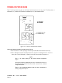
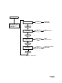
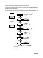
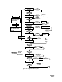
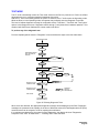
Entry to Configuration mode starts with a Main menu, allowing the user to select one of four submenus.
The Main menu includes the following submenu options:
"View Config"
This is the entry point into the Configuration menu. Press the SELECT switch
to enter a submenu allowing the user to view the drive operating parameters,
firmware revisions and hardware serial numbers. Press the MENU switch to
select the next option in the Main menu.
"Set Config"
Press the SELECT switch to enter a submenu allowing the user to select and
set the drive operating parameters. Press the MENU switch to select the next
option in the Main menu.
"Diagnostics"
Press the SELECT switch to enter a submenu allowing the user to display
diagnostic parameters or perform diagnostic operations. Diagnostics includes
the "Park Drive" option to prepare the drive for shipping. Press the MENU
switch to select the next option in the Main menu.
"Set Serial #"
Press the SELECT switch to enter the Set Serial # submenu thereby allowing
the user to set the right digit of the serial number. Press MENU to advance to
the next digit in the serial number. Press SELECT to change the value of
each digit.
NOTE
The serial number set in the drive must correspond to the last 5 digits
of the drive's actual serial number for accurate internal event logging
to occur. The drive's actual serial number is written on the back of the
drive enclosure.
A structure diagram for the Main menu is shown in the next figure.
To move up a level in the Configuration menu hierarchy, press the LOAD/MENU and TEST/SELECT
switches simultaneously.
To exit the Configuration mode, press the LOAD/MENU and TEST/SELECT switches simultaneously from
the Main menu. The display will show the message which appeared prior to the drive entering the
Configuration mode.
The "Ready" message is displayed when a media cartridge is loaded on the drive spindle.
PLASMON L M S - LF 8120 USER MANUAL
Page 44
MAIN MENU
View Config
PRESS BOTH SWITCHES
SIMULTANEOUSLY FROM
ANY MENU TO RETURN TO
THE MAIN MENU
SELECT
ENTER VIEW
CONFIG MENU
SELECT
ENTER
SET CONFIG MENU
SELECT
ENTER
DIAGNOSTIC MENU
SELECT
ENTER SERIAL NUMBER
ENTRY MENU
MENU
Set Config
MENU
Diagnostics
MENU
Set Serial #
MENU
Figure 18. Main Menu
97664106 A
Page 45
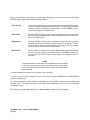
VIEWING THE CONFIGURATION ("VIEW CONFIG")
To view the configuration, press the TEST/SELECT switch while "View Config" is displayed in the Main
menu. The drive will enter the View Configuration menu which includes the following options:
"View Current"
Press the SELECT switch to display the current drive operating parameters.
The operating parameters are listed in the table below. Press the MENU
switch to select the next option in the View Configuration menu.
"View FW Revs"
Press the SELECT switch to display the drive firmware revisions. These
include firmware revisions for the WOODI, DPC, RWS A and RWS B. Press
the MENU switch to select the next option in the View Configuration menu.
"View HW S/Ns"
Press the SELECT switch to display the serial numbers. These include serial
numbers for the Drv SN, Woodi, Rws A, Rws B, Oma A, Oma B, and Dpc.
Press the MENU switch to select the next option in the View Configuration
menu.
"View HW P/Ns"
Press the SELECT switch to display the hardware part numbers. These
include part numbers for WOODI, RWS A, RWS B and DPC. Press the
MENU switch to select the next option in the View Configuration menu.
Table 9. View Configuration Messages
OPTION
NAME
CURRENT
SETTING
DEFAULT FACTORY
SETTING
# 0 - 15
0
On or Off
On
Eng, Frh or Grm
Eng
On or Off
Off
AutoLoad
Slot 1-12 or MRU
1
Load SW
On or Off
On
Rd Ahead
On or Off
Off
CDE Curs
On or Off
Off
Busy
On or Off
On
ModSelRA
On or Off
On
MMSpinUp
On or Off
Off
TargSDTR
On or Off
On
TargWDTR
On or Off
On
SCSI ID
Parity
Language
Wrt Prot
PLASMON L M S - LF 8120 USER MANUAL
Page 46
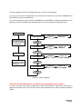
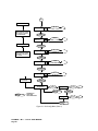
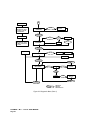
A structure diagram for the View Configuration menu is shown in the next figure.
To move up a level in the Configuration menu hierarchy to the Main menu, press the LOAD/MENU and
TEST/SELECT switches simultaneously.
To exit the Configuration mode, press the LOAD/MENU and TEST/SELECT switches simultaneously. The
display will show the message which appeared prior to the drive entering the Configuration mode.
MAIN MENU
View Current
PRESS BOTH SWITCHES
SIMULTANEOUSLY FROM
VIEW CONFIG TO RETURN
TO THE MAIN MENU
SELECT
DISPLAY CURRENT
SELECTIONS
MENU
View FW Revs
SELECT
DISPLAY FW
REVISIONS
MENU
VIEW CONFIG MENU
View HW S/Ns
PRESS BOTH SWITCHES
SIMULTANEOUSLY FROM
ANY MENU TO RETURN TO
VIEW CONFIG
SELECT
DISPLAY HW
SERIAL NUMBERS
MENU
View HW P/Ns
SELECT
DISPLAY HW
PART NUMBERS
MENU
Figure 19. View Config Menu
SETTING THE CONFIGURATION OF THE OPERATING PARAMETERS ("SET CONFIG")
To enter the mode to set the drive configuration, press the TEST/SELECT switch while "Set Config" is
displayed in the Main menu. The drive will enter the Set Configuration menu which includes the following
options:
97664106 A
Page 47
"Set Defaults"
Press the SELECT switch to set all drive operating parameters to the factory defaults.
Press the MENU switch to select the next option in the Set Configuration menu.
"SCSI ID"
Press the SELECT switch to scroll through the possible SCSI ID values (0 through
15). When the desired ID value is displayed, press the MENU switch to enter that
value as the SCSI ID and select the next option in the Set Configuration menu.
"Parity"
Press the SELECT switch to turn parity checking on or off. SCSI bus parity generation
is always enabled but SCSI bus parity checking by the drive may be turned on or off.
When the desired state (on or off) is displayed, press the MENU switch to enter that
state for parity checking and select the next option in the Set Configuration menu.
"Language"
Press the SELECT switch to scroll through the language options (Eng = English, Frh =
French, Grm = German) for the DOC operating messages. When the desired
language option is displayed, press the MENU switch to enter that option and select
the next option in the Set Configuration menu.
"Wrt Prot"
Press the SELECT switch to turn write protect on or off. When the desired state (on or
off) is displayed, press the MENU switch to enter that state for write protect and select
the next option in the Set Configuration menu.
"AutoLoad"
Press the SELECT switch to scroll through the Auto Load options. The drive
can be configured to load the cartridge residing in a specific slot 0 - 12 or the
Most Recently Used (MRU) cartridge. When the desired option is displayed,
press the MENU switch to enable that option and select the next option in the
Set Configuration menu.
"Load SW"
Press the SELECT switch to enable or disable the LOAD switch on the DOC. When
the desired state (on or off) is displayed, press the MENU switch to enter that state for
load switch and select the next option in the Set Configuration menu.
"Rd Ahead"
Press the SELECT switch to turn read ahead on or off. When the desired state (on or
off) is displayed, press the MENU switch to enter that state for read ahead and select
the next option in the Set Configuration menu.
"CDE Curs"
Press the SELECT switch to turn the CDE indicator (a blinking solid cursor in the
rightmost display position) on or off. When the desired state (on or off) is displayed,
press the MENU switch to enter that state for CDE Curs and select the next option in
the Set Configuration Menu.
"Busy"
Press the SELECT switch to toggle the Busy option between On and Off. When the
desired mode has been selected, press the LOAD/MENU switch to select the next
option.
"ModSelRA"
Press the SELECT switch to toggle the Mode Select Read Ahead option between On
and Off. When the desired mode has been selected, press the LOAD/MENU switch to
select the next option.
"MMSpinUp"
Press the SELECT switch to toggle the Media Management Spin Up option between
On and Off. When the desired mode has been selected, press the LOAD/MENU
switch to select the next option.
"Negotiation"
Press SELECT switch to toggle between TargSDTR OFF or ON. Press MENU to
switch to TargSWTR. Press SELECT again to toggle between TargSWTR OFF and
ON. When the desired selections have been made, press MENU and SELECT
simultaneously to return to the NEGOTIATIONS menu.
PLASMON L M S - LF 8120 USER MANUAL
Page 48
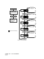
A structure diagram for the Set Configuration menu is shown in the next figure.
To move up a level in the configuration menu hierarchy to the Main menu, press the LOAD/MENU and
TEST/SELECT switches simultaneously.
To exit the Configuration mode, press the LOAD/MENU and TEST/SELECT switches simultaneously. The
display will show the message which appeared prior to the drive entering the Configuration mode.
MAIN MENU
PRESS BOTH SWITCHES
SIMULTANEOUSLY FROM
SET CONFIG TO RETURN
TO THE MAIN MENU
SET VALUES
TO DEFAULT
SELECT
SET DEFAULT
MENU
SCSI ID
0
SELECT
0
7
SET CONFIG MENU
MENU
SELECT
PARITY
ON
ON
OFF
PRESS BOTH SWITCHES
SIMULTANEOUSLY FROM
ANY MENU TO RETURN TO
SET CONFIG
MENU
SELECT
LANGUAGE
ENG
ENG
FRH
GRM
MENU
SELECT
WrtProt
OFF
ON
OFF
MENU
SELECT
AutoLoad
1
1 - 12/
MRU
MENU
SELECT
Load SW
ON
ON
OFF
MENU
A
FROM LAST MENU
SELECTION
Figure 20. Set Config Menu (Part 1)
97664106 A
Page 49
A
MAIN MENU
SELECT
Rd Ahead
OFF
OFF
ON
PRESS BOTH SWITCHES
SIMULTANEOUSLY FROM
SET CONFIG TO RETURN
TO THE MAIN MENU
MENU
OFF
SELECT
CDE Curs
OFF
ON
SET CONFIG MENU
MENU
SELECT
PRESS BOTH SWITCHES
SIMULTANEOUSLY FROM
ANY MENU TO RETURN TO
SET CONFIG
Busy
ON
ON
OFF
MENU
SELECT
ModSel RA
ON
ON
OFF
MENU
SELECT
MM SpinUp
ON
OFF
OFF
CYCLE BACK TO
TOP OF MENU
MENU
Negotiation
SELECT
TargSDTR
SELECT
OFF
ON
MENU
MENU
SELECT
PRESS BOTH
= SWITCHES
SIMULTANEOUSLY
MENU
SELECT
TargWDTR
SELECT
OFF
ON
MENU
Figure 21. Set Config Menu (Part 2)
PLASMON L M S - LF 8120 USER MANUAL
Page 50
SELECT
SET DEFAULTS
The SET DEFAULT function will reset all operating parameters to factory defaults.
Perform the following procedure to set the LF 8120's to the factory defaults:
1. Enter the Configuration mode by pressing both the LOAD/MENU and TEST/SELECT
switches simultaneously.
2. Press the MENU switch until "Set Config" is displayed.
3. Press the SELECT switch to enter the Set Configuration menu. "SET DEFAULTS" will be
displayed.
4. Press SELECT to set parameters to the factory defaults.
5. Simultaneously press the LOAD/MENU and TEST/SELECT switches to move up to the Main
menu. Simultaneously press the LOAD/MENU and TEST/SELECT Switches again to exit
Configuration mode.
SETTING THE SCSI ID
The SCSI ID can be set to one of 16 device Identification (ID) numbers (0 through 15); however, each
device connected to the same SCSI bus must have a unique SCSI ID.
Perform the following procedure to set the LF 8120's SCSI ID number:
1. Enter the Configuration mode by pressing both the LOAD/MENU and TEST/SELECT
switches simultaneously.
2. Press the MENU switch until "Set Config" is displayed.
3. Press the SELECT switch to enter the Set Configuration menu.
4. Press the MENU switch until "SCSI ID" is displayed.
5. Press the SELECT switch to scroll through the options for the SCSI ID value (0 through 15).
When the desired value is displayed for the SCSI ID, press MENU to enter the SCSI ID value
and move to the next option in the Set Configuration menu.
6. Simultaneously press the LOAD/MENU and TEST/SELECT switches to move up to the Main
menu. Simultaneously press the LOAD/MENU and TEST/SELECT Switches again to exit
Configuration mode.
NOTE
After resetting the device ID, turn the drive off, wait 5 sec and then
turn the drive on again. This ensures that the new device ID will be
acknowledged by the SCSI bus.
97664106 A
Page 51
SETTING THE BUS PARITY CHECKING
SCSI bus parity generation is always enabled; however, SCSI bus parity checking at the drive can be
disabled.
Perform the following procedure to turn parity checking on or off:
1. Enter the Configuration mode by pressing both the LOAD/MENU and TEST/SELECT
switches simultaneously.
2. Press the MENU switch until "Set Config" is displayed.
3. Press the SELECT switch to enter the Set Configuration menu.
4. Press the MENU switch until "Parity:" is displayed.
5. Press the SELECT switch to scroll through the states for parity checking (on, off). When the
desired state is displayed, press MENU to enter the state and move to the next option in the
Set Configuration menu.
6. Simultaneously press the LOAD/MENU and TEST/SELECT switches to move up to the Main
menu. Simultaneously press the LOAD/MENU and TEST/SELECT switches again to exit
Configuration mode.
SETTING THE LANGUAGE
The language option enables the user to select the language used by the LF 8120 to display messages in
the Operating mode. (English is the only available language for Configuration mode.)
Perform the following procedure to set the operating mode display language:
1. Enter the Configuration mode by pressing both the LOAD/MENU and TEST/SELECT
switches simultaneously.
2. Press the MENU switch until "Set Config" is displayed.
3. Press the SELECT switch to enter the Set Configuration menu.
4. Press the MENU switch until "Language:" is displayed.
5. Press the SELECT switch to scroll through the language display options (Eng = English, Frh =
French, Grm = German). When the desired language option is displayed, press MENU to
enter the language option and move to the next option in the Set Configuration menu.
6. Simultaneously press the LOAD/MENU and TEST/SELECT switches to move up to the Main
menu. Simultaneously press the LOAD/MENU and TEST/SELECT switches again to exit
Configuration mode.
PLASMON L M S - LF 8120 USER MANUAL
Page 52
SETTING THE WRITE PROTECT OPTION
The write protect option enables the user to inhibit the LF 8120 from writing to any media inserted into the
drive, regardless of the write protect setting on the media cartridges.
Perform the following procedure to turn write protect on or off:
1. Enter the Configuration mode by pressing both the LOAD/MENU and TEST/SELECT
switches simultaneously.
2. Press the MENU switch until "Set Config" is displayed.
3. Press the SELECT switch to enter the Set Configuration menu.
4. Press the MENU switch until "Wrt Prot:" is displayed.
5. Press the SELECT switch to scroll through the states for write protect (off, on). When the
desired state is displayed, press MENU to enter the state and move to the next option in the
Set Configuration menu.
6. Simultaneously press the LOAD/MENU and TEST/SELECT switches to move up to the Main
menu. Simultaneously press the LOAD/MENU and TEST/SELECT switches again to exit
Configuration mode.
NOTE
The Write Protect indicator on the DOC is illuminated when write
protect is enabled.
SETTING THE MEDIA AUTOLOAD OPTION
The media AutoLoad load option enables a user to choose which media cartridge is automatically inserted
and loaded at power up and whenever the LOAD/MENU switch is pressed while in the Operating mode.
The factory default selects the cartridge in slot 1. The options are 1 - 12 or Most Recently Used (MRU).
Perform the following procedure to set the LF 8120's AutoSpin option:
1. Enter the Configuration mode by pressing both the LOAD/MENU and TEST/SELECT
switches simultaneously.
2. Press the MENU switch until "Set Config" is displayed.
3. Press the SELECT switch to enter the Set Configuration menu.
4. Press the MENU switch until "AutoLoad:" is displayed.
5. Press the SELECT switch to scroll through the Auto Load options. The drive can be
configured to load the cartridge residing in a specific slot 0 - 12 or the Most Recently Used
(MRU) cartridge. When the desired option is displayed, press the MENU switch to enable
that option and select the next option in the Set Configuration menu.
6. Simultaneously press the LOAD/MENU and TEST/SELECT switches to move up to the Main
menu. Simultaneously press the LOAD/MENU and TEST/SELECT switches again to exit
Configuration mode.
97664106 A
Page 53
SETTING THE LOAD SWITCH OPTION
The load switch option enables the user to enable or disable the LOAD/MENU switch on the DOC. The
LOAD/MENU switch can be disabled to prevent accidentally spinning down a media cartridge. This also
prevents cartridge loading from the DOC, giving the host exclusive control of media loading.
Perform the following procedure to enable or disable the LOAD/MENU switch:
1. Enter the Configuration mode by pressing both the LOAD/MENU and TEST/SELECT
switches simultaneously.
2. Press the MENU switch until "Set Config" is displayed.
3. Press the SELECT switch to enter the Set Configuration menu.
4. Press the MENU switch until "Load SW:" is displayed.
5. Press the SELECT switch to scroll through the states for the load switch (on, off). When the
desired state is displayed, press MENU to enter the state and move to the next option in the
Set Configuration menu.
6. Simultaneously press the LOAD/MENU and TEST/SELECT switches to move up to the Main
menu. Simultaneously press the LOAD/MENU and TEST/SELECT switches again to exit
Configuration mode.
SETTING THE READ AHEAD OPTION
The read ahead option often improves the overall read data transfer rate of the LF 8120 in applications
which require continuous blocks of data to be read (as compared to the same subsystem without read
ahead).
Perform the following procedure to turn read ahead on or off:
1. Enter the Configuration mode by pressing both the LOAD/MENU and TEST/SELECT
switches simultaneously.
2. Press the MENU switch until "Set Config" is displayed.
3. Press the SELECT switch to enter the Set Configuration menu.
4. Press the MENU switch until "Rd Ahead:" is displayed.
5. Press the SELECT switch to scroll through the states for read ahead (off, on). When the
desired state is displayed, press MENU to enter the state and move to the next option in the
Set Configuration menu.
6. Simultaneously press the LOAD/MENU and TEST/SELECT switches to move up to the Main
menu. Simultaneously press the LOAD/MENU and TEST/SELECT switches again to exit
Configuration mode.
PLASMON L M S - LF 8120 USER MANUAL
Page 54
CAUTION
The read ahead option is system dependent. Ensure that you check
with your system analyst before setting this option.
When enabled, the read ahead option uses the data buffer (12.8 MBytes) to store data sectors read from
the disk beyond those sectors requested by the host. Subsequent sequential sectors will be read directly
from the buffer instead of incurring the latency time it takes to access sequential sectors. (Refer to the
LD 8100/ LF 8120/ LF 8600/ LF 8602 SCSI Interface Specification, P/N 97662164.)
SETTING THE CDE CURS OPTION
The CDE Curs (Controller Detected Error) option enables a blinking solid cursor in the rightmost character
location of the DOC panel when a CDE has occurred. In most system installations, the host system will
recover from reported CDE's and no user intervention is required. A developer may wish to enable this
indicator during system development or installation.
Perform the following procedure to turn CDE Curs on or off:
1. Enter the Configuration mode by pressing both the LOAD/MENU and TEST/SELECT
switches simultaneously.
2. Press the MENU switch until "Set Config" is displayed.
3. Press the SELECT switch to enter the Set Configuration menu.
4. Press the MENU switch until "CDE Curs:" is displayed.
5. Press the SELECT switch to scroll through the states for CDE Curs (off, on). When the
desired state is displayed, press MENU to enter the state and move to the next option in the
Set Configuration menu.
6. Simultaneously press the LOAD/MENU and TEST/SELECT switches to move up to the main
menu. Simultaneously press the LOAD/MENU and TEST/SELECT switches again to exit
Configuration mode.
97664106 A
Page 55
SETTING THE BUSY OPTION
When enabled, the “Busy” message is displayed at the DOC during a spin up or spin down operation.
Enabling this option will cause the Drive to respond to a Start command (via SCSI or MCLI) with a "BUSY"
message over SCSI.
Perform the following procedure to enable or disable the BUSY option:
1. Enter the Configuration mode by pressing both the LOAD/MENU and TEST/SELECT
switches simultaneously.
2. Press the MENU switch until "Set Config" is displayed.
3. Press the SELECT switch to enter the Set Configuration menu.
4. Press the MENU switch until "Busy:" is displayed.
5. Press the SELECT switch to scroll through the states for the load switch (on, off). When the
desired state is displayed, press MENU to enter the state and move to the next option in the
Set Configuration menu.
6. Simultaneously press the LOAD/MENU and TEST/SELECT switches to move up to the main
menu. Simultaneously press the LOAD/MENU and TEST/SELECT switches again to exit
Configuration mode.
SETTING THE MODSEL RA OPTION
ModSel RA setting determines if the Drive will acknowledge a Mode Select from the host that changes the
state of the Read Ahead. When disabled, the Drive will ignore a MODSEL RA send over SCSI.
Perform the following procedure to enable or disable the ModSel RA option:
1. Enter the Configuration mode by pressing both the LOAD/MENU and TEST/SELECT
switches simultaneously.
2. Press the MENU switch until "Set Config" is displayed.
3. Press the SELECT switch to enter the Set Configuration menu.
4. Press the MENU switch until "ModSelRA:" is displayed.
5. Press the SELECT switch to scroll through the states for the load switch (on, off). When the
desired state is displayed, press MENU to enter the state and move to the next option in the
Set Configuration menu.
6. Simultaneously press the LOAD/MENU and TEST/SELECT switches to move up to the main
menu. Simultaneously press the LOAD/MENU and TEST/SELECT switches again to exit
Configuration mode.
PLASMON L M S - LF 8120 USER MANUAL
Page 56
SETTING THE MM SPINUP OPTION
When enabled, the (Media Management Spin Up) MM SpinUp option allows the LaserDrive to read
necessary media management information during spin up. If not enabled, the media management
information will be recovered on the first media access command.
Perform the following procedure to enable or disable the MM SpinUp option:
1. Enter the Configuration mode by pressing both the LOAD/MENU and TEST/SELECT
switches simultaneously.
2. Press the MENU switch until "Set Config" is displayed.
3. Press the SELECT switch to enter the Set Configuration menu.
4. Press the MENU switch until "MMSpinUp:" is displayed.
5. Press the SELECT switch to scroll through the states for the load switch (off, on). When the
desired state is displayed, press MENU to enter the state and move to the next option in the
Set Configuration menu.
6. Simultaneously press the LOAD/MENU and TEST/SELECT switches to move up to the main
menu. Simultaneously press the LOAD/MENU and TEST/SELECT switches again to exit
Configuration mode.
SELECT TARGET NEGOTIATION
The Negotiation menu allows the Drive to be set to initiate the NEGOTIATE for SCSI Wide and SCSI
Synchronous communication.
Perform the following procedure to enable or disable the MM SpinUp option:
1. Enter the Configuration mode by pressing both the LOAD/MENU and TEST/SELECT
switches simultaneously.
2. Press the MENU switch until "Set Config" is displayed.
3. Press the SELECT switch to enter the Set Configuration menu.
4. Press the MENU switch until "Negotiation" is displayed.
5. Press SELECT switch. "TargSDTR" is displayed. Press SELECT to toggle between OFF or
ON.
6. When the desired selection has been made, press MENU to display TargWDTR.
7. Press SELECT to toggle between OFF and ON.
8. Simultaneously press the LOAD/MENU and TEST/SELECT switches to move up to the main
menu. Simultaneously press the LOAD/MENU and TEST/SELECT switches again to exit
Configuration mode.
97664106 A
Page 57
VIEWING DIAGNOSTIC RESULTS OR PERFORMING DIAGNOSTIC
OPERATIONS ("DIAGNOSTICS")
To enter the diagnostic submenu, press the TEST/SELECT switch while "Diagnostics" is displayed in the
Main menu. The drive will enter the Diagnostics menu which includes the following options:
"Park Drive"
Press the SELECT switch to park the baseplates for drive shipment. If the
"Park Failed, Close Manually" message appears, refer to the Manual Release
section of this manual. Press the MENU switch to select the next option in the
Diagnostics menu.
"Test Sensors"
Press the SELECT switch to enter sensor display mode. In sensor display
mode the DOC panel will display the status of the sensors within the drive.
For details, see the LF 8120 Hardware Maintenance Manual (P/N 97663082).
Press the MENU switch to select the next option in the Diagnostics menu.
"Clear NvRAM"
CAUTION
Since the initialization variables cannot
be recovered once they are cleared, this
operation should only be performed by a
trained Customer Engineer (CE).
Press the SELECT switch; the message "Drive will reset and NvRAM will be
cleared! To Continue Press Select" will appear. Press the MENU switch if you
do not want to clear the nonvolatile memory (NvRAM) initialization variables;
press the SELECT switch to clear the NvRAM initialization variables in the
drive. Press the MENU switch to select the next option in the Diagnostics
menu.
"Cal Shuttle"
Press SELECT switch; the message "Is Shuttle calibration required?" will be
displayed. Press SELECT switch again and follow all instructions that are
displayed on the DOC. After calibration is complete, press the SELECT and
MENU switch to select the next option in the Diagnostics menu.
"View CDEs"
Press the SELECT switch to view the controller detected error (CDE). The
DOC will display the error code. When no error has occurred, the "No CDE
Error" message is displayed. The error code is cleared upon exiting the
Diagnostics menu. The error code should be logged by the operator for aiding
the CE in diagnosing the drive problem. Press the MENU switch to select the
next option in the Diagnostics menu.
"Baud"
Press the SELECT switch to cycle through the available baud rates. When
the desired is displayed, press MENU to go to the next menu item.
PLASMON L M S - LF 8120 USER MANUAL
Page 58
"Test Start"
Press the SELECT switch to select the Test to be performed (0 - 9). Once the
desired test has been selected, press MENU to select the Test End value
(see the next table for the test value and test name).
"Test End"
Press the SELECT switch to select last Test to be performed (0 - 9). Once the
desired test has been selected, press MENU to select the Test Cycle value
(see the next table for the test value and test name).
Table 10. Diagnostics Selftests
TEST #
DESCRIPTION OF TEST
0
Power-on self-test. This test cannot be disabled; it runs
automatically when the drive is powered on.
1
PCA Self-tests, DPR Communication
2
Read/Write Data Path
3
OMA
4
Cartridge Guide Sensors
5
Shuttle, Baseplate and Spindle Motor Operation
6
Servo Control Systems
7
Read Performance
8
Reserved
9
Write Power Calibration
"Test Cycles"
Press the SELECT switch to select the number of times the test(s) is to be
performed. Use the MENU switch cycle through all four digits. Press the
MENU switch to select the next option in the Diagnostics Menu.
"View RTPM"
Press the SELECT switch to view the RTPM (Real Time Performance
Monitor) status. If no RTPM error has occurred, the DOC will display "No
RTPM Err". If an RTPM error has occurred, the DOC will display the media
serial number and drive channel combination which caused the RTPM error.
The media serial number will be displayed for 5 sec (S/N: ########) and
then the drive channel will be displayed for 4 sec (Channel: A, B, or A+B).
The display will then return to the View RTPM option.
97664106 A
Page 59
"Clear RTPM"
CAUTION
RTPM errors indicate the drive or media require maintenance, and place the
drive in a read only mode. Corrective action may be as simple as cleaning the
media that caused the error, or may require the attention of a trained
Customer Engineer (CE) to repair the drive. Clearing this error without
resolving the cause may reduce the total media capacity because of
abnormally high relocations during write operations.
Press the SELECT switch; if an RTPM error has not occurred, the message
"No RTPM Err" will briefly appear and the display will return to "Clear RTPM".
If an RTPM has occurred, a confirmation message will be displayed. Press
the SELECT switch to clear the RTPM error and enable writing. Press the
MENU switch to select the next option in the Diagnostic (Park Drive) menu
without clearing the RTPM error. The drive will not perform write operations
with an RTPM error.
"Init DPC"
Press SELECT switch to Initialize DPC. This option will clear all the serial
E-Prom values and reset the drive.
"WPC Options"
Press the SELECT switch. "Force WPC" is displayed. If Write Calibration is
required, press the SELECT switch again. The Drive will cycle through the
WPC Write, WPC GOOD, and back to Force WPC messages.
Press the MENU switch to display Clear WPC. If the WPC log needs to be
cleared from the Drive, press SELECT again. When the WPC Log has been
cleared, the message WPC CLEARED will be momentarily displayed. When
Clear WPC is displayed, press MENU and MENU/SELECT simultaneously to
return to the Diagnostic Menu.
A structure diagram for the Diagnostics menu is shown in the next figure.
To move up a level in the configuration menu hierarchy to the Main menu, press the LOAD/MENU and
TEST/SELECT switches simultaneously.
To exit the Configuration mode, press the LOAD/MENU and TEST/SELECT switches simultaneously from
the Main menu. The display will show the message which appeared prior to the drive entering the
Configuration mode.
PLASMON L M S - LF 8120 USER MANUAL
Page 60
Park Drive
SELECT
MENU
Test Sensors
MAIN MENU
Enter Sensor
SELECT
Display Mode
SELECT
PRESS BOTH SWITCHES
SIMULTANEOUSLY FROM
SET CONFIG TO RETURN
TO THE MAIN MENU
MENU
Confirm Clear
SELECT
Clear NV RAM
SELECT
SET CONFIG MENU
MENU
Follow all instructions
displayed on DOC
SELECT
PRESS BOTH SWITCHES
SIMULTANEOUSLY FROM
ANY MENU TO RETURN TO
SET CONFIG
Cal Shuttle
SELECT
MENU
View CDEs
FROM LAST MENU
SELECTION
Display Default
Information
SELECT
MENU
SELECT
19.2Kb
38.4Kb
57.6Kb
115.2Kb
BAUD: 19.2 kb
MENU
SELECT
0
9
Test Start: 0
MENU
MENU SELECT
PRESS BOTH
= SWITCHES
SIMULTANEOUSLY
Test End: 0
MENU
SELECT
SELECT
Cycles:
0001
0
9
SELECT
0001
9999
Test Cycles
MENU SELECT
MENU
A
Figure 22. Diagnostics Menu (Part 1)
97664106 A
Page 61
A
MAIN MENU
PRESS BOTH SWITCHES
SIMULTANEOUSLY FROM
SET CONFIG TO RETURN
TO THE MAIN MENU
Display RTPM
Information
SELECT
View RTPM
MENU
SET CONFIG MENU
RTPM
True
SELECT
PRESS BOTH SWITCHES
SIMULTANEOUSLY FROM
ANY MENU TO RETURN TO
SET CONFIG
Y
Confirm Clear
N
SELECT
Clear RTPM
No RTPM Err
RTPM Condition is Cleared
MENU
To top of Menu
SELECT
Reset Drive
Init Done
Init DPC
Self Test
MENU
MENU SELECT
WPC Options
SELECT
Force WPC
SELECT
Will Force a
single WPC
SELECT
Will Clear Drive
WPC Log
MENU
Clear WPC
MENU SELECT
MENU
MENU SELECT
PRESS BOTH
= SWITCHES
SIMULTANEOUSLY
Figure 23. Diagnostic Menu (Part 2)
PLASMON L M S - LF 8120 USER MANUAL
Page 62
SET THE INTERNAL DRIVE SERIAL NUMBER ("SET SERIAL #")
To enter the serial number submenu, press the TEST/SELECT switch while "Set Serial #" is displayed in
the Main menu. The drive will enter the menu allowing the operator to view and change the internal drive
serial number.
NOTE
The serial number set in the drive must correspond to the last 5 digits
of the drive's actual serial number for accurate internal event logging
to occur. The drive's actual serial number is located on the back of the
drive enclosure.
To change the drive's 5-digit serial number, follow these steps:
1) Enter the Configuration mode by simultaneously pressing the LOAD/MENU and TEST/
SELECT switches.
2. Press the MENU switch until "Set Serial #" is displayed.
3. Press the SELECT switch to enter the serial number mode. The serial number will be
displayed.
4. If the serial number does not require revision, simultaneously press the LOAD/MENU and
TEST/SELECT switches to move up to the Main menu. Simultaneously press the LOAD/
MENU and TEST/SELECT switches again to exit Configuration mode.
If the serial number requires revision, press the MENU switch until the digit position to be
changed is blinking. Then press the SELECT switch until the desired digit value is
displayed. Continue to select digit positions and values until the correct serial number is
displayed.
5. Simultaneously press the LOAD/MENU and TEST/SELECT switches to move up to the
Main menu. Simultaneously press the LOAD/MENU and TEST/SELECT switches again
to exit Configuration mode.
A structure diagram for the Set Serial # menu is shown in the next figure.
97664106 A
Page 63
SELECT
MAIN MENU
0
.
DRV SN 1
PRESS BOTH SWITCHES
SIMULTANEOUSLY FROM
THE SET SERIAL # MENU
TO RETURN TO THE MAIN
MENU
2
3
4
5
.
9
Blank
MENU
SELECT
0
.
SET CONFIG MENU
DRV SN 1
2
3
4
5
.
9
Blank
MENU
PRESS BOTH SWITCHES
SIMULTANEOUSLY AFTER
SETTING A DIGIT TO
RETURN TO THE SET
SERIAL # MENU
SELECT
0
DRV SN 1
2
3
4
.
.
5
9
Blank
MENU
SELECT
0
.
DRV SN 1
N
2
3
4
5
.
9
Blank
= Digit to be Set is Flashing
MENU
SELECT
0
DRV SN 1
2
3
4
MENU
Figure 24. Set Serial # Menu
PLASMON L M S - LF 8120 USER MANUAL
Page 64
5
.
.
9
Blank
TEST MODE
The LF 8120 automatically enters the Test mode each time the Drive is powered on. Power-on selftest
diagnostics are run to verify the operational readiness of the drive.
After the LF 8120 successfully passes the power-on selftests, the LF 8120 enters the Operating mode.
While the Drive is in the Operating mode, the operator may manually enter the Diagnostic Test mode.
The level of selftest diagnostic coverage is configurable via the "Test Start:", "Test End" and "Test Cycles"
options in the Diagnostics menu. Diagnostic tests 0 through 7 verify basic drive hardware operation. Test
number 9 will Write Power Calibrate the current media in the Drive.
To perform any of the diagnostic test:
From the Operating Mode enter the "Diagnostic" menu and follow the steps in the flow chart below:
ENTER DIAGNOSTIC MENU
DIAGNOSTICS
SELECT
PRESS MENU REPEATEDLY
UNTIL TEST START 0: IS
DISPLAYED
MENU
SELECT
0
9
Test Start: 0
MENU
SELECT
Test End: 0
MENU
SELECT
0
9
Cycles: 0001
SELECT
0001
9999
Test Cycles
MENU SELECT
SWITCH BACK TO THE
"DIAGNOSTIC" MENU
MENU
SELECT
SWITCH BACK TO THE
"OPERATING" MENU
MENU
SELECT
START TESTING
PRESS BOTH
MENU SELECT = SWITCHES
SIMULTANEOUSLY
SELECT
FOLLOW INSTRUCTIONS
DISPLAYED ON THE DOC
Figure 25. Entering Diagnostic Tests
When errors are detected, the appropriate diagnostic message will be displayed on the DOC. Diagnostic
messages are presented to the operator in the form of failed test codes and Field Replaceable Unit (FRU)
mnemonics that can be relayed to a CE for repairing the malfunction.
If no problems are detected by the system function diagnostics, the display will show "Diagnostics
Complete. Press TEST to restart drive...".. Pressing TEST resets the Drive.
97664106 A
Page 65
MEDIA CARTRIDGE HANDLING
The LM 8000 or LM 6000 media cartridge may be used in all LD 8100/LF 8120/LF 8600/LF 8602 drives.
The media cartridge is shipped ready for immediate use and does not require preformatting before use.
The LF 8120 accesses both sides of the media cartridge (see next figure). The LM 8000 cartridge must be
inserted with side A facing right while the LM 6000 cartridge may be inserted into the LF 8120 with either
side facing left.
SIDE A VIEW
SIDE A IDENDIFICATION
MEDIA LOADING
NOTCHES
CARTRIDGE DOOR
(BOTH SIDES)
COLOR PLUG
(FOR CARTRIDGE ID)
MEDIA DIRECT
LABEL
WRITE PROTECT SWITCH
AND INDICATOR
BLOCKED GRIPPER
HOLE
Figure 26. LM 8000 Media Cartridge
The media cartridge also has a write protect switch which write protects both sides of the media when the
switch is in the active position.
PLASMON L M S - LF 8120 USER MANUAL
Page 66
Observe the following precautions to ensure data integrity when handling or storing a media cartridge:
1) Do not drop the media cartridge onto hard surfaces.
2. Do not physically abuse the cartridge exterior or access mechanisms.
3. Do not store the media cartridge in the drive.
4. Remove cartridges from the drive when the drive is going to be moved.
5. Apply labels only in designated areas. Refer to the Affixing Label section for instructions
on label placement.
6. Avoid exposing the media cartridge to direct sunlight and condensation.
CAUTION
Careful attention to the environmental constraints specified in the
LM 8000 Media Specification (P/N 97663080) is strongly
recommended to prevent damage to the media.
7. Do not expose the media cartridge to temperature extremes.
8. Stabilize the media cartridge to the specified operating temperature range 1 hr before use.
9. Do not open the media access shutter.
10. Do not touch the disk surface through the media access shutter.
11. Do not remove the disk from the cartridge.
12. Use, handle and store the media cartridge in clean office conditions.
13. Do not smoke while handling the media. Smoke is a prime source of disk contamination.
All smoking materials should be kept away from areas where the media are in use or
storage.
14. Keep external surfaces of the cartridge clean. Dust the cartridge periodically with a soft,
dry, lint-free cloth.
97664106 A
Page 67
SETTING THE WRITE PROTECTION SWITCH
To manually write protect a cartridge, set the write protect switch on the data cartridge as indicated in the
next figure.
WRITE PROTECT
SWITCH
NOT
WRITE PROTECTED
WRITE
PROTECTED
(NOT WRITE PROTECTED
HOLE IS OPEN
WRITE PROTECTED
HOLE IS CLOSED)
WRITE PROTECT SWITCH
AND INDICATOR
(ON OTHER SIDE)
EP004350
Figure 27. Manually Write Protecting the Media Cartridge
PLASMON L M S - LF 8120 USER MANUAL
Page 68
AFFIXING LABELS
Title and content labels are supplied with each LM 8000 media cartridge and should be affixed before the
cartridge is inserted into the LF 8120. Before affixing the labels in the recessed areas (see figure below),
ensure that the surface of the cartridge is clean and dry.
SIDE A VIEW
POSITION
LABELS HERE
Figure 28. Label Placement
97664106 A
Page 69
MEDIA INSERTION AND REMOVAL
Individual media cartridges are inserted and removed through the front panel media access door. When
fully closed, the door is held by magnetic contacts. A safety switch prevents operation of the shuttle if the
door is open. When the door is opened and closed, the drive tests the six slots to determine which slots
have media cartridges present.
The door is automatically locked by a electrical safety lock when the drive begins operation. An
independent manual key lock, located in the bezel assembly, provides an additional locking method for
preventing unauthorized media access.
Operator access to the media requires the shuttle to be in the home position. The home shuttle position
squarely aligns all six cartridge slots with the media access door as illustrated in the next figure.
SAFETY LOCK
LATCH KEY LOCK
DOOR SAFETY SWITCH
KEY LOCK
DOOR LATCH (2X)
Figure 29. LF 8120 Media Access
Returning the shuttle to home can be accomplished by host command or by pressing LOAD/MENU at the
DOC. If access is authorized, the drive will unload the media cartridge into the shuttle, move the shuttle to
the home position, and unlock the electrical safety door lock. If access is denied by command from the
host, pressing LOAD/MENU will have no effect and the DOC will briefly display the "Denied" message.
PLASMON L M S - LF 8120 USER MANUAL
Page 70
CARTRIDGE INSERTION
LM 8000 media cartridges are inserted directly into the LF 8120 shuttle via the media access door
described in the Media Access Door section. Ensure that the arrows on the cartridge point toward the
shuttle and insert the cartridge into the slot until it is fully seated and its back edge is flush with the edge of
the shuttle.
ENSURE THAT CARTRIDGES
DIRECTIONAL ARROWS
POINT IN TOWARD THE SHUTTLE
INSERTION
DIRECTION
ARROWS
CARTRIDGE
SIDE B
Figure 30. Media Cartridge Insertion
97664106 A
Page 71
CARTRIDGE REMOVAL
LM 8000 media cartridges may be removed from the media access door. To aid in removing the closely
spaced cartridges, the top rear edge of the shuttle is cut away and a notch is provided on the exposed
edge of each cartridge. Pulling on the cartridge notch with one finger as shown in the next figure, will back
the cartridge out far enough so that it can be grasped and removed.
Figure 31. Media Cartridge Removal
PLASMON L M S - LF 8120 USER MANUAL
Page 72
MANUAL CARTRIDGE RELEASE MECHANISM
If power fails or if the drive fails with a media cartridge inserted, the media cartridge can be manually
removed by opening the drive baseplates, removing the bezel and then retracting the cartridge.
OPENING THE BASEPLATES
With the manual release tool, perform the following procedure:
1) Move the AC power switch to the OFF ( O ) position and disconnect the AC power cable
from the wall outlet.
2. At the rear panel, insert the manual release tool into the upper access hole and engage
the recessed D-shaped shaft. Turn the tool handle counterclockwise as far as it will turn
to open the upper baseplate.
3. Repeat step 2) at the lower access hole to open the lower baseplate.
UPPER
ACCESS
HOLE
MANUAL RELEASE
TOOL
LF 8120 SKIN
NOT SHOWN
REAR PANEL
LOWER ACCESS
HOLE
Figure 32. Manually Opening the LF 8120 Baseplates
97664106 A
Page 73
RETRACTING THE CARTRIDGE
Use the following procedure to manually retract a cartridge:
1. Insert the manual release tool onto the D-shaped shaft at
the front of the drive as shown in the figure above to operate
the cartridge insertion mechanism. Turn the tool clockwise as
far as it will turn, pulling the cartridge back into the shuttle.
INSERT MANUAL
RELEASE TOOL HERE
Figure 33. LF 8120 Manual Cartridge Retraction
2. Manually move the shuttle to the home position as shown below.
3. Remove the cartridge from the shuttle slot.
PLASMON L M S - LF 8120 USER MANUAL
Page 74
MANUALLY MOVE THE SHUTTLE
TO THE LEFT INTO THE SHIPPNG
POSITION
Figure 34. Manually Moving the Shuttle Assembly to the Home Position
MEDIA LOADING
Individual media cartridges can be selected for loading by host command or by the autoload configuration
option. The host can select and load a media cartridge from any shuttle slot by issuing an appropriate
SCSI bus command.
Selection by the autoload configuration option occurs at initial power up and when the LOAD/MENU switch
on the DOC is pressed while the LF 8120 is in Operating mode. Depending on the setting of the autoload
option, the LF 8120 automatically inserts and loads one specified media cartridge or the most recently
used (MRU) cartridge or moves the shuttle to the home position.
If the selected cartridge is not present, the DOC displays "# Empty", where # represents cartridges 1-12.
For more information on viewing and setting drive configuration options, refer to the Configuration Mode
section of this manual.
97664106 A
Page 75
PLASMON L M S - LF 8120 USER MANUAL
Page 76
OPERATOR MAINTENANCE
INSPECTING AND CLEANING FAN AND BLOWER FILTERS
Inspect the Filters at the rear of the drive on a 1 - 6 month schedule and clean, if necessary, to ensure that
cooling air flow is not restricted. If the drive is exposed to excessive amounts of dust, decrease the time
between inspection intervals.
Remove dust on the drive's exterior with a dry, lint-free cloth. Dust can migrate to the media cartridge and
cause performance degradation.
CAUTION
Failure to maintain a clean Filter Element can reduce air flow through
the drive. This will create high temperatures in the LF 8120 which may
shorten the life of the drive.
Perform the following procedure to clean the Filter Elements:
1. Set the drive's AC power switch to the OFF ( O ) position and verify that the fan and blower
have stopped running.
2. Remove each Outer Grill Half by grasping its sides and pulling it away from the chassis.
3. Remove each Filter Element by pulling it away from the inside of the Grill.
4. Wash the Filter Element in warm soapy water.
5. Rinse the Element thoroughly and let it air dry.
6. Re-install the Filter Element in the Outer Grill Half.
7. Replace the Outer Grill Half by snapping it onto the inner Grill
97664106 A
Page 77
LF 8120 SKIN
NOT SHOWN
BLOWER
FAN
FILTER GRILL
ASSEMBLY
OUTER GRILL HALF
EP006058
Figure 35. Removing Filter Element
REPLACING FUSES
As stated in the Drive Characteristics section of this manual, two fuses and two spare fuses are integrated
into the power receptacle on the rear panel of the LF 8120 (refer to the figure below). If the drive will not
power up, one or both of the fuses may have blown.
To replace a blown fuse with a spare fuse:
1. Set the drive's AC power switch to the OFF ( O ) position and remove the AC power cord.
2. Insert a small, flat-blade screwdriver between the fuse holder and the receptacle housing, as
shown.
3. Gently pry the fuse holder open. Slide the fuse holder out of the receptacle and visually
inspect the active fuse to determine if it is blown. If the active fuse is blown, proceed to step
4); otherwise, proceed to 5).
4. Remove the active fuse and discard it. Remove the spare fuse from its storage location and
insert the fuse between the fuse housing and the retaining clip.
5. Re-install the fuse holder into the receptacle, sliding the holder into the receptacle until the
holder is aligned flush with the receptacle housing.
6. Apply power to the unit (refer to the Power - On Procedure).
7. If power is not restored, check the other fuse.
PLASMON L M S - LF 8120 USER MANUAL
Page 78
RETAINING
CLIP
ACTIVE FUSE
SPARE FUSE
IN STORAGE
LOCATION
FUSE HOLDERS
FUSE
HOUSING
AC POWER
RECEPTACLE
EP006079
Figure 36. Removing Fuse from AC Power Receptacle (Rear View of LF 8120)
WARNING
If a spare fuse blows immediately after you have replaced the original
fuse, contact your next level of support.
Do not replace the spare fuse. This may be a symptom of a more
serious problem, either with the power supply or the power system.
97664106 A
Page 79
MEDIA CLEANING
Media disk surfaces should be inspected periodically and cleaned on an as-needed basis.
MEDIA CLEANING USING CLEANING KIT P/N 97662550
The Cleaning Kit P/N 97662550 provides a semi-automated cleaning method for cleaning the Plasmon
LM 4000, LM 6000 and LM 8000 12 inch optical media. Follow the procedures given in the enclosed
Cleaning Instructions.
The Kit contains the following items:
•
One 12 inch media cleaning fixture
•
Two containers of cleaning liquid
•
Five packages of cleaning tissues
•
One pair of protective gloves
•
Cleaning Instructions
PLASMON L M S - LF 8120 USER MANUAL
Page 80
APPENDIX A
GERMAN TRANSLATIONS/ÜBERSETZUNGEN INS
DEUTSCHE
ABMESSUNGEN UND GEWICHT
Die Bezugsabmessungen für den LF 8120 (wie auch aus Abbildung 4 ersichtlich) betragen wie folgt:
Höhe:
75.57 cm
Breite:
45.10 cm
Tiefe:
58.42cm
Der LF 8120 wiegt 75.75 kg.
TEMPERATUR, LUFTFEUCHTIGKEIT UND SEEHÖHE
In Tabelle 1 sind die Temperatur-, Luftfeuchtigkeits- und Meereshöhengrenzwerte für die im LF 8120
installierten LF 8120-Laufwerke aufgeführt.
Tabelle 1. Temperatur-, Luftfeuchtigkeits- und Höhengrenzwerte
BETRIEB
RUHE
LAGERUNG/
TRANSPORT(1)
10 bis 42 C2
-40 bis 66 C
-40 bis 66 C
11 C/h
20 C/h
20 C/h
10 bis 90%
5 bis 95%
5 bis 95%
Maximale
Änderungsrate
10%/h
10%/h
10%/h
Maximale
Feuchtkugel-temperatur3
28 C
46 C
46 C
Minimale Taupunkt
2 C
2 C
2 C
BEDINGUNG
Temperatur
Maximale
Änderungsrate
Luftfeuchtigkeit
(Nicht Kondensierend)
Lagerung: -300 bis 3000 m
Seehöhe4
-300 bis 3000 m
Transport: -300 bis 12000 m
97664106 A
Page 81
1 Die Lagerungsangaben beziehen sich auf maximal 90 Tage in der Plasmon LMS-Verpackung. Kondensation ist nicht
zulässig. Die Transportangaben gelten für maximal 1 Woche in einem werkseitig verschlossenen Behälter.
2 Falls nicht anders angegeben ist die maximale Betriebstemperatur für ein freistehendes Laufwerk auf Meereshöhe. 42 C.
Die maximale Betriebstemperatur über 300 m Höhe wird bei 2000 m Höhe linear auf 38 C herabgesetzt.
3 Weitere Informationen zu Temperatur- und Luftfeuchtigkeitsgrenzwerten im Betriebszustand finden Sie in der Produktspezifikation für den LD 8100/ LF 8600/LF 8120 .
4 Für Datenträger gilt ein Grenzwert von 2000 m. Umgebungsbedingungen und Grenzwerte für Datenträger finden Sie in
der Produktspezifikation für den LM 8000-Datenträger.
STOSS UND VIBRATION
In Tabelle 2 sind die Stoß- und Vibrationskriterien und -grenzwerte für den LF 8120 angegeben:
Tabelle 2. Stoß- und Vibrationskriterien und -Grenzwerte
BETRIEB
RUHE1
LAGERUNG/
TRANSPORT2
Wobbelvibration
(Bidirektional)
1 Oktave/Minute
5 bis 250 Hz 0,1 Zoll
Doppelamplitude
250 bis 500 Hz, 0,25 g
Peak
5 bis 44 Hz 0,03 Zoll
Doppelamplitude
44 bis 500 Hz, 3,0 g
Peak
5 bis 44 Hz 0,03 Zoll
Doppelamplitude
44 bis 500 Hz, 3,0 g
Peak
Stoss3
(Hostwiederholungen Sind
U.u.
Erforderlich
Und
Laufwerksleistung Kann Sich
Während
Des
Tests
Verschlechtern)
10 msek.
Halb- Sinusimpuls Von
2.5 g Peak4
BEDINGUNG
Unverpackt
(3 Achsen)
Verpackt Auf
Palette
5msek.HalbSinusimpuls
20 g Peak
Verpackt Auf
Palette
46 cm Fallversuch
- Flach
1 Mit entfernten Datenträgern
2
In LMS-genehmigter Verpackung
3 Die Häufigkeit wiederholter Stoßeinwirkungen ist so weit gering zu halten, daß mechanische bzw. elektrische Störungen
zwischen den einzelnen Stößen wieder nachlassen.
WECHSELSTROMBEDARF
Der primäre Netzkabeltyp hängt von der bestellten Konfiguration für den LF 8120 ab. Das primäre
Netzkabel versorgt die Steckdosenleiste im Gehäuse des LF 8120 mit Strom.
PLASMON L M S - LF 8120 USER MANUAL
Page 82
Jeder LF 8120 ist über ein geerdetes Netzkabel an die Steckdosenleiste angeschlossen. Beim LF 8120 ist
der Verbindungstecker in die Netzsteckdose integriert. Schutz gegen Überlaststrom wird durch zwei
Sicherungen gewährleistet, die zusammen mit zwei Reservesicherungen in die Netzsteckdose integriert
sind. Das Netzteil jedes Laufwerks erfordert die in Tabelle 3 angegebenen Netzspannungen.
Das Netzteil ist selbstregulierend und erfordert kein mechanisches Schalten der Eingangsspannung oder
Netzfrequenz.
Tabelle 3. Wechselstrombedarf
FREQUENZ
WECHSELSPANNUNG
LEISTUNG
(TYPISCH)
EINSCHALTSTROMSTOSS1
NENNLEISTUNG,
MIN
47 bis 66 Hz
95.0 V bis 128 V
1,4 A
10,0 A
15 A
47 bis 66 Hz
173,4 bis 268 V
0,7 A
5,0 A
15 A
1 Weniger als 1 Sek., Kaltstarthinweis
HINWEIS
Nach Ausschalten des Stroms müssen Sie 1 Sekunde warten, bevor
der Strom wieder eingeschaltet werden darf.
WECHSELSTROMERDUNG
Um einen sicheren Betrieb zu gewährleisten, muß das Gehäuse des LF 8120 geerdet sein. Das
Wechselstromkabel enthält eine Erdleitung, die das Gehäuse des LF 8120 durch die
Wechselstromversorgung des Standorts an Sicherheitserde legt. Die Wechselstromversorgung des
Standorts wiederum muß diese Erdung an einen Erdanschluß legen. Alle Wechselstromverbindungen am
Standort müssen denselben Erdanschluß verwenden.
Ein Erdanschlußteil an der Geräterückseite (vgl. Abschnitt 2.2.) kann ebenfalls dazu verwendet werden,
den LF 8120 an einen Erdanschluß zu legen. Dieser Erdanschlußteil ist ein 6 mm M4-Bolzen mit Mutter
und Sicherungsscheibe.
KIPPTOLERANZ
Ermöglicht den Kippbetrieb von der waagrechten Stellung.
WÄRMEAUSSTRAHLUNG
Das Gehäuse des LF 8120 weist während eines Schreib-/Lesevorgangs eine typische Wärmebelastung
von 292 kcal/h (1160 BTU/h) auf. Wenn Datenträgerkassetten mit der Maximalgeschwindigkeit des
Laufwerks eingelegt, geladen, aktiviert, deaktiviert, entladen und entfernt werden, beträgt die typische
Wärmebelastung des LF 8120 ungefähr 364 kcal/h (1450 BTU/h).
97664106 A
Page 83
WARNHINWEISE
Der LF 8120 ist als Lasergerät eingestuft und unterliegt den US-amerikanischen Anforderungen bezüglich
Lasergeräte. Die in Abbildung 5 dargestellten Warnhinweise sind erforderlich, um den USBundesvorschriften nachzukommen. Diese Warnhinweise dürfen nicht von den Laufwerken im Gehäuse
des LF 8120 entfernt werden.
AUSPACHEN DER LF 8120
WARNUNG
Um Personenverletzungen zu vermeiden, darf der LF 8120 nicht ohne
geeignete Hilfsvorrichtungen angehoben werden.
Beim Auspacken und Transport des LF 8120 ist sicherzustellen, daß
die Einheit um nicht mehr als 10 Grad gekippt wird. Der LF 8120 wiegt
über 181 kg. Wenn die Einheit um mehr als 10 Grad gekippt wird,
kann sie unversehens umfallen und zu Personenverletzungen führen.
WARNUNG
Um Personenverletzungen zu vermeiden, sind zwei Personen
erforderlich, um den LF 8120 auf einer Rampe nach unten zu rollen.
Hierbei ist sicherzustellen, daß die Einheit um nicht mehr als 10 Grad
gekippt wird. Der LF 8120 wiegt über 181 kg. Wenn die Einheit um
mehr als 10 Grad gekippt wird, kann sie unversehens umfallen und zu
Personenverletzungen führen.
WIEDERVERPACKEN DES LF 8120
Der LF 8120 sollte nur in seiner Originalverpackung wiederverpackt werden. Vor dem Wiederverpacken
sind die Grundplatten jedes Laufwerks zu schließen (weiteres hierüber finden Sie unter Schritt 2 im
nachfolgenden Verfahren).
PLASMON L M S - LF 8120 USER MANUAL
Page 84
VORSICHT
Die Grundplatten der Laufwerke müssen sich in geschlossener
Stellung befinden, bevor der LF 8120 transportiert wird. Nur so kann
eine nicht unter den Garantieschutz fallende Beschädigung der
Laufwerke vermieden werden.
WARNUNG
Der LF 8120 darf nicht ohne geeignete Hilfsvorrichtungen angehoben
werden.
WARNUNG
Um Personenverletzungen zu vermeiden, sind zwei Personen
erforderlich, um den LF 8120 auf einer Rampe nach oben zu rollen.
Hierbei ist sicherzustellen, daß die Einheit um nicht mehr als 10 Grad
gekippt wird. Der LF 8120 wiegt über 181 kg. Wenn die Einheit um
mehr als 10 Grad gekippt wird, kann sie unversehens umfallen und zu
Personenverletzungen führen.
INSTALLATIONSANFORDERUNGEN
VORSICHT
Vor dem Einschalten der Laufwerke des LF 8120 müssen die
Transportblöcke aus Schaumstoff aus den Wagenvorrichtungen
entfernt werden.
97664106 A
Page 85
Wenn der LF 8120 in ein Gerätegestell oder -Gehäuse eingebaut ist,
stellen Sie sicher, daß die interne Temperatur des Gestells oder
Gehäuses die in der Produktspezifikation und dem vorliegenden
Handbuch angegebenen Betriebsgrenzen nicht überschreiten.
Senkrecht gestapelte Einheiten erfordern spezielle Aufmerksamkeit
im oberen Bereich, in dem höhere Temperaturen herrschen.
Sie müssen das LF 8120 an eine Stromversorgung anschließen, die
eine direkte Erdung hat
(Netzwerk-/Erdungsverbindung TT =
Terminated Terra). Diese Einheit ist nicht für den Einsatz mit einer
schwimmenden Erdung (Netzwerk IT = Interrupted Terra)
vorgesehen.
Achten Sie darauf, daß das Laufwerk an eine Stromversorgung mit
ausreichender Stromstärke angeschlossen ist.
WARNUNG
Um Brand oder Elektroschock zu vermeiden, darf der LF 8120 weder
Regen noch Feuchtigkeit ausgesetzt werden. Wartungsarbeiten
dürfen nur von qualifizierten Technikern ausgeführt werden.
Trennen Sie die Einheiten im Falle eines Brandes oder einer anderen
Notsituation von der Hauptstromversorgung, indem Sie die Stecker
aus den Steckdosen ziehen. Sollte das Herausziehen der Stecker
nicht
möglich
oder
praktisch
sein,
trennen
Sie
die
Hauptstromversorgung.
Die betriebsfremde Benutzung von Bedienelementen oder Reglern
oder die Durchführung von Verfahren, die im vorliegenden Handbuch
nicht beschrieben sind, kann zu einer gefährlichen Belastung durch
Laserstrahlung führen.
Vermeiden Sie es, direkt in den Laserstrahl oder dessen
Rückstrahlung auf einer reflektierenden Oberfläche zu blicken.
Unsichtbare Laserstrahlung kann freigesetzt werden, wenn die
Einheit offen ist und die Sicherheitsverriegelungen außer Kraft gesetzt
sind.
ANSCHLUßÜBERPRÜFUNG
Vor dem Einschalten des Systems sind folgende Schritte durchzuführen:
1) Überprüfen Sie, ob der Host-Adapter, falls vorhanden, ordnungsgemäß abgeschlossen ist.
2) Überprüfen Sie, ob der letzte LF 8120 im Bus, falls ein Bus vorhanden, ordnungsgemäß
abgeschlossen ist.
PLASMON L M S - LF 8120 USER MANUAL
Page 86
VORSICHT
Vor dem Einschalten der Laufwerke ist sicherzustellen, daß die
Transportblöcke aus Schaumstoff aus den Wagenvorrichtungen
entfernt wurden.
Anweisungen zum Einschalten des Systems finden Sie in Abschnitt 5 des vorliegenden Handbuchs.
WARNUNG
Setzen Sie die Verriegelung des LF 8120 nicht außer Kraft, und
öffnen Sie nicht beide Laufwerke gleichzeitig.
EINSCHALTVERFAHREN
HINWEIS
Die Seriennummer, die dem Laufwerk zugeordnet wird, muß mit den
letzten 5 Ziffern der tatsächlichen Seriennummer des Laufwerks
übereinstimmen, damit eine exakte interne Ereignisprotokollierung
stattfinden kann. Die tatsächliche Seriennummer des Laufwerks
befindet sich an der Rückseite des Laufwerksgehäuses.
EINSTELLEN DIE "DEICE ID"
HINWEIS
Schalten Sie das Laufwerk nach Rücksetzung der Gerätekennung
aus, warten Sie 1 Sekunde und schalten Sie das Laufwerk dann
wieder ein. Dies stellt sicher, daß die neue Gerätekennung vom SCSIBus anerkannt wird.
EINSTELLEN DIE "READ OPTION"
VORSICHT
Die Option "Read ahead" ist systemabhängig. Setzen Sie sich mit
Ihrem Systemanalytiker in Verbindung, bevor Sie diese Option
einstellen.
97664106 A
Page 87
ANZEIGEN DER DIAGNOSEERGEBINISSE ODER DURCHFÜREN VON DIAGNOSERVER
FAHREN
VORSICHT
Da die Initialisierungsvariablen nicht wiederhergestellt werden
können, nachdem sie gelöscht wurden, sollte dieser Vorgang nur von
einem ausgebildeten Ingenieur des Kundendienstes durchgeführt
werden.
EINSTELLEN DER INTERNEN LAUFWERKSSERIENNUMMER ("SERIENNR. EINSTELLEN")
HINWEIS
Die Seriennummer, die dem Laufwerk zugeordnet wird, muß mit den
letzten 5 Ziffern der tatsächlichen Seriennummer des Laufwerks
übereinstimmen, damit eine exakte interne Ereignisprotokollierung
stattfinden kann. Die tatsächliche Seriennummer des Laufwerks
befindet sich an der Rückseite des Laufwerksgehäuses.
HANDHABUNG VON DATENTRÄGERKASSETTEN
Achten Sie bei der Handhabung und Lagerung von Datenträgerkassetten auf die folgenden
Vorsichtsmaßnahmen, um die Datenintegrität zu sichern.
1) Die Datenträgerkassette niemals auf harte Flächen fallen lassen.
2) Das Kassettengehäuse oder den Zugriffsmechanismus nicht mißbrauchen.
3) Die Datenträgerkassette nicht im Laufwerk lagern.
4) Die Kassetten vor einem Transport aus dem Laufwerk entfernen.
5) Etiketten nur an den vorgesehenen Stellen anbringen.
6) Die Datenträgerkassette vor direkter Sonneneinstrahlung und Kondensation schützen.
PLASMON L M S - LF 8120 USER MANUAL
Page 88
VORSICHT
Zur Vermeidung einer Beschädigung der Datenträger wird dringendst
empfohlen, die in der Spezifikation für LM 8000-Datenträger
angegebenen Umgebungsbeschränkungen sorgfältig zu beachten.
7) Die Datenträgerkassette nicht extremen Temperaturen aussetzen.
8) Die Datenträgerkassette eine Stunde
Betriebstemperaturbereich stabilisieren.
vor
Gebrauch
auf
den
angegebenen
9) Die Zugangsabdeckung des Datenträgers nicht öffnen.
10) Die Plattenoberfläche nicht durch die Zugangsabdeckung berühren.
11) Die Magnetplatte nicht aus der Kassette herausnehmen.
12) Die Datenträgerkassetten in einer sauberen Büroumgebung benutzen, handhaben und
lagern.
13) Während der Handhabung von Datenträgern nicht rauchen. Asche und Tabak sind eine
Hauptquelle für die Verunreinigung von Magnetplatten. Alle Rauchutensilien sind aus
den Bereichen fernzuhalten, in denen Datenträger benutzt oder gelagert werden.
14) Die Außenflächen der Kassetten sauber halten. Die Kassetten regelmäßig mit einem
weichen, trockenen, fusselfreien Tuch reinigen.Weitere Informationen zur Pflege und
Handhabung von Datenträgern finden Sie in der Spezifikation für den LM 8000Datenträger.
WARNUNG
Setzen Sie die Verriegelung des LF 8120 nicht außer Kraft, und
öffnen Sie nicht beide Laufwerke gleichzeitig.
97664106 A
Page 89
VORSICHT
Wenn die Gebläsefilterelemente nicht sauber gehalten werden, kann
die Luftzirkulation im Laufwerk beeinträchtigt werden. Dies kann zu
einem übermäßigen Temperaturanstieg und damit zu einer
Beschädigung der Laufwerke führen.
AUSWECHSELN VON SICHERUNGEN
Wie in Abschnitt 2.6. des vorliegenden Handbuchs dargestellt, sind zwei Sicherungen und zwei
Ersatzsicherungen in die Netzbuchse an der Geräterückseite des LF 8120 eingebaut (vgl. Abbildung 40).
Wenn sich das Laufwerk nicht einschalten läßt, könnte eine oder beide Sicherungen durchgebrannt sein.
So tauschen Sie eine durchgebrannte Sicherung gegen eine Ersatzsicherung aus:
1) Stellen Sie den Wechselstromschalter des Laufwerks auf AUS (0), und ziehen Sie das
Netzkabel ab.
2) Fügen Sie einen kleinen Flachschraubenzieher zwischen dem Sicherungshalter und dem
Gehäuse der Buchse ein (vgl. Abbildung 40).
3) Öffnen Sie den Sicherungshalter vorsichtig. Ziehen Sie den Sicherungshalter aus der
Buchse heraus und überprüfen Sie die aktive Sicherung, um festzustellen, ob sie
durchgebrannt ist. Wenn die Sicherung durchgebrannt ist, fahren Sie mit Schritt 4) fort,
ansonsten mit Schritt 5).
4) Entfernen Sie die aktive Sicherung und entsorgen Sie sie. Nehmen Sie die
Ersatzsicherung aus deren Aufbewahrungsort und fügen Sie die Sicherung zwischen
dem Sicherungsgehäuse und der Halteklammer ein.
5) Installieren Sie den Sicherungshalter wieder in der Buchse; schieben Sie dabei den Halter
in die Buchse, bis der Halter bündig auf das Gehäuse der Buchse ausgerichtet ist.
6) Wenn die Stromversorgung nicht wiederhergestellt wird, prüfen Sie die andere Sicherung.
PLASMON L M S - LF 8120 USER MANUAL
Page 90
WARNUNG
Sollte eine Ersatzsicherung unmittelbar nach dem Ersetzen der
Originalsicherung entfallen, dürfen Sie diese Sicherung nicht mehr
ersetzen.
Wenden Sie sich an die nächste Stufe technischer Unterstützung.
Dies könnte das Symptom eines schwerwiegenderen Problems sein,
das entweder am Netzteil des Laufwerks oder in der Stromversorgung
liegt.
97664106 A
Page 91
Storing More Of Your
Digital World ™. Permanently.