1
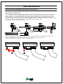
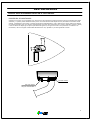
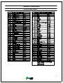
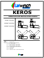
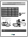
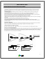
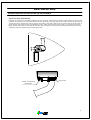
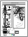
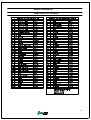
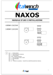
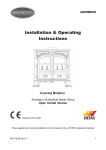
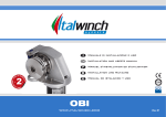
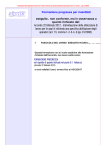
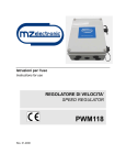
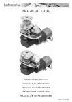
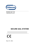
KEROS
MANUALE D'USO E INSTALLAZIONE
700W 12V/24V
1000W 12V/24V
1400W 12V/24V
I
PAG.
PAG.
PAG.
PAG.
PAG.
PAG.
PAG.
PAG.
PAG.
PAG.
1: INTRODUZIONE.
2: CARATTERISTICHE TECNICHE
3/4/5: INSTALLAZIONE.
6: SCHEMA ELETTRICO MOTORE 2 POLI
7: SCHEMA ELETTRICO MOTORE 3 POLI
8: SCHEMA ELETTRICO MOTORE 4 POLI
9/10: PARTI RICAMBIO 700W 1000W 1400W.
11: MANUTENZIONE.
12: USO.
13: TERMINI DI GARANZIA - TARGHETTA DI IDENTIFICAZIONE DEL MODELLO.
1
CARATTERISTICHE TECNICHE
VI PREGHIAMO DI LEGGERE ATTENTAMENTE LE ISTRUZIONI D'USO E DI MONTAGGIO DEL PRESENTE
MANUALE PRIMA DI OPERARE E INSTALLARE IL SALPA-ANCORA
KEROS
MODELLO
VERSIONE
700 12V / 24V
1000 12V / 24V
1400 12V / 24V
POTENZA MOTORE
700 W
1000 W
1400 W
TIRO ISTANTANEO MASSIMO
750 KG
900 KG
1200 KG
CARICO DI LAVORO MASSIMO
250 KG
350 KG
450 KG
CARICO DI LAVORO
90 KG
130 KG
130 KG
130A(12V) 80A(24V)
130A(12V) 80A(24V)
130A(12V) 80A(24V)
23.2-31 m/min.
23.2-31 m/min.
23.2-31 m/min.
VELOCITA' DI RECUPERO AL CARICO DI LAVORO (2)
18-24 m/min.
18-24 m/min.
18-24 m/min.
CATENA SUPPORTATA (3)
6-8-10
6-8-10
6-8-10
SEZIONE MINIMA CAVI MOTORE (4)
50mm(12V) 35mm(24V)
50mm(12V) 35mm(24V)
70mm(12V) 35mm(24V)
INTERRUTTORE DI PROTEZIONE (5)
125A(12V) 70A(24V)
125A(12V) 70A(24V)
150A(12V) 70A(24V)
SPESSORE COPERTA (6)
25-50 mm
25-50 mm
25-50 mm
PESO KEROS SENZA CAMPANA
KG 18 CIRCA
KG 20 CIRCA
KG 24 CIRCA
PESO KEROS CON CAMPANA
KG 19 CIRCA
KG 21 CIRCA
KG 25 CIRCA
ANGOLO DI LAVORO DEL TUBO (7)
45°/90°
45°/90°
45°/90°
VELOCITA DI BASCULAZIONE DEL TUBO (8)
90° IN 5" CIRCA
90° IN 5" CIRCA
90° IN 5" CIRCA
ASSORBIMENTO DI CORRENTE AL CARICO DI
LAVORO (1)
VELOCITA' MASSIMA DI RECUPERO (2)
ATTENERSI ALLO SPESSORE
INDICATO IN TABELLA
(1) DOPO UN PRIMO PERIODO D'USO
(2) LA VELOCITA VARIA DAL TIPO DI CATENA E BARBOTIN MONTATI
(3) BARBOTIN DI SERIE PER CATENA DA 8mm
(4) VALORE MINIMO
(5) CON INTERRUTTORE SPECIFICO PER CORRENTI CONTINUE E RITARDATO
(6) SU RICHIESTA POSSONO ESSERE FORNITI SALPA-ANCORA PER SPESSORI DI
COPERTA MAGGIORI
(7) REGOLAZIONE MECCANICA IN FASE D'OPERA
(8) VELOCITA RIFERITA AD UN SALPA-ANCORA DI 50 GIRI AL MINUTO
VERSIONE SENZA CAMPANA
PRUA
TIPO
KEROS 1000
KEROS 1400
A
76
76
B
110
110
C
139
139
D
180
180
E
F
25/50 149
25/50 149
G
68
79
H
245
280
I
114
114
L
250
250
M
165
165
N
117
117
O
175
195
P
118
118
Q
255
255
R
90
90
2
INSTALLAZIONE
VI PREGHIAMO DI LEGGERE ATTENTAMENTE LE ISTRUZIONI D'USO E DI MONTAGGIO DEL PRESENTE
MANUALE PRIMA DI OPERARE E INSTALLARE IL SALPA-ANCORA
-I
salpa-ancora integrati ITALWINCH sono stati esclusivamente realizzati per salpare l'ancora, non sono dei punti di
forza, non utilizzare questi apparecchi per altri usi, l'uso improprio potrebbe causare danni al salpa-ancora o a
persone.
-La ITALWINCH non si assume nessuna responsabilità per danni diretti o indiretti causati per uso improprio a
persone o cose.
-Il salpa-ancora non è stato progettato per reggere l'imbarcazione in particolari condizioni di tempo
(burrasca o per tempesta).
-Disattivare sempre il salpa-ancora quando non è in uso per prevenire azionamenti accidentali.
-Non eccedere nel carico, Vi suggeriamo di assistere il salpa-ancora durante l'operazione di recupero e calata in
mare dell'ancora, dirigendo l'imbarcazione nel punto di ancoraggio alla minima velocità.
-Accertarsi che non vi siano bagnanti o imbarcazioni nelle vicinanze prima di calare l'ancora.
-Installare sempre un appropriato interruttore magneto termico per proteggere il circuito e il motore elettrico da
surriscaldamenti o danni.
-Bloccare la catena con un fermo (schiavetto) prima di partire per la navigazione.
-Tenere sempre mani e piedi lontano dal salpa-ancora quando è in azione.
-Se la catena si incastra disattivare il salpa-ancora e con estrema cautela tentare di liberare la catena.
-Tutta la parte elettrica (motore, teleruttore, centraline) va montata al riparo da schizzi o getti d'acqua.
MATERIALE PRESENTE NELLA CONFEZIONE:
Salpa-ancora completo di parte superiore compreso stendicatena e motoriduttore cassetta teleruttori/teleinvertitori,
leva, viterie per l'assemblaggio, dima di foratura, manuale d'uso e installazione.
ATTREZZI NECESSARI PER L'INSTALLAZIONE:
Trapano con punta Ø10 sega a tazza Ø30 - Ø50 - Ø85, chiavi esagonali 10mm, 13mm, chiave a brugola 3mm
silicone.
REQUISITI PER L'INSTALLAZIONE:
Il salpa-ancora va posizionato cercando di mantenere la catena il più possibile allineata al puntale di prua, una
volta individuata la posizione per il montaggio verificare che le superfici siano il più parallele possibili se non
lo sono levigare opportunamente lo spessore della coperta sia quello indicato in tabella e che sotto la coperta il
motoriduttore, catena, tubo disponicatena e i cavi non abbiano interferenze o ostacoli.
ATTENERSI ALLO SPESSORE
INDICATO IN TABELLA
ANCORA
ANCORA
40cm
3
INSTALLAZIONE
VI PREGHIAMO DI LEGGERE ATTENTAMENTE LE ISTRUZIONI D'USO E DI MONTAGGIO DEL PRESENTE
MANUALE PRIMA DI OPERARE E INSTALLARE IL SALPA-ANCORA
PROCEDURA
DI MONTAGGIO:
Una volta stabilita la posizione di montaggio praticare i fori con la dima fornita a corredo, lisciare il più possibile
il foro in corrispondenza del passaggio della catena, seperare le due parti del salpa-ancora, siliconare con la
massima attenzione il perimetro sottostante della parte superiore del salpa-ancora, montare la parte superiore
del salpa-ancora in corrispondenza dei fori praticati precedentemente, collegare la parte inferiore a quella
superiore avendo cura di lasciare spazio per il brandeggiamento del tubo (tenere presente che la catena si disporra
meglio nella parte più profonda del gavone), fissare il salpa-ancora serrando i dadi
sui prigionieri, togliere il silicone in eccesso,
SI
LI
C
E
N
O
Montare il kit camma biella già pre-assemblati: avvitare il perno sul collare e allo stesso tempo montare la
camma sull'alberino conico avendo cura di rispettare la fase con la linguetta, montare la
rosetta antisvitamento e il dado sull'alberino e stingere a fondo.
4
INSTALLAZIONE
VI PREGHIAMO DI LEGGERE ATTENTAMENTE LE ISTRUZIONI D'USO E DI MONTAGGIO DEL PRESENTE
MANUALE PRIMA DI OPERARE E INSTALLARE IL SALPA-ANCORA
PROCEDURA
DI MONTAGGIO:
collegare il motore con gli appositi cavi provenienti dal teleruttore (togliere tensione prima di operare sulla parte
elettrica), a questo punto effettuare delle prove di funzionamento del salpa-ancora, facendolo funzionare senza
catena, il dispositivo comincera' a funzionare facendo brandeggiare il tubo, definire solo come disporre la catena
nel gavone avendo cura che l'angolo di brandeggio del tubo non interferisca con nessun ostacolo (motore, pareti)
e che la catena si disponga nel punto più basso del gavone, stingere a fondo la vite presente sul collare e se
necessario, ridurre l'angolo di basculata allentando la vite, spostare e poi stringendola a fondo.
vite del collare
vite che regola
l'angolo di basculata
5
7
LISTA RICAMBI
LISTA RICAMBI KEROS
CON STENDICATENA INTEGRATO
9
MANUTENZIONE
LISTA RICAMBI KEROS
10
MANUTENZIONE
ATTENZIONE PRIMA DI COMPIERE OPERAZIONI DI MANUTENZIONE SUL
SALPA-ANCORA TOGLIERE COMPLETAMENTE LA TENSIONE A TUTTA LA LINEA DEL
SALPA-ANCORA, RIMUOVERE CON CURA LA CATENA E TOGLIERE LA CIMA DALLA
CAMPANA.
Un'attenta e periodica manutenzione allunga la vita del Vostro salpa-ancora, rimuovere periodicamente almeno
una volta al mese i depositi di sale che si formano sulle superfici, per evitare pericolosi fenomeni di corrosione,
lavare con acqua dolce le superfici esterne e asciugare accuratamente.
Smontare almeno una volta all'anno la campana e il barbotin seguendo le istruzioni sotto elencate:
VERSIONE CON LA CAMPANA:
Con la chiave (19) svitare il volantino (28) rimuovere la campana (33), il cono frizione (25), svitare le viti della
cuffia (14), rimuovere la cuffia (13) e lo staccacatena (12), estrarre il barbotin (24).
VERSIONE SENZA CAMPANA:
Con la chiave(19) svitare il volantino (28) rimuovere il copribarbotin (27), il cono frizione (25), svitare le viti
della cuffia (14), rimuovere la cuffia (13) e lo staccacatena (12), estrarre il barbotin (24).
Pulire e controllare tutti i particolari affinchè non presentino tracce di corrosione, rimuovere se presente la
corrosione con un panno, non usare abrasivi, ingrassare con grasso marino il filetto dell'albero, l'albero stesso
(11) e il barbotin dove è a contatto con i coni frizione (22) (25), il filetto del volantino e rimontare il tutto.
Per le parti elettriche rimuovere l'ossido presente specialmente sui contatti del motore e teleruttore/teleinvertitore
con uno spray per contatti elettrici e cospargerli con grasso.
PARTI DI RICAMBIO:
Per identificare un ricambio esaminare il disegno esploso pag 10, ricavarne il codice e la quantità necessaria,
ordinare il ricambio allegando il numero di matricola presente sul salpa-ancora.
11
USO
-EVITARE DI AVVICINARSI O AVVICINARE OGGETTI AL SALPA-ANCORA QUANDO E'
IN FUNZIONE, TOGLIERE TENSIONE QUANDO SI OPERA MANUALMENTE ANCHE
QUANDO SI ALLENTA LA FRIZIONE, PERSONE PRESENTI A BORDO POTREBBERO
AZIONARE ACCIDENTALMENTE IL SALPA-ANCORE CON IL CONTROLLO REMOTO O IL
TELECOMANDO.
-BLOCCARE LA CATENA PRIMA DI PARTIRE PER LA NAVIGAZIONE, IL SALPA-ANCORA
NON DEVE ESSERE UTILIZZATO COME UNICO PUNTO DI FORZA PER LA CATENA.
-NON ATTIVARE IL SALPA-ANCORA CON LA CHIAVE PER LA FRIZIONE INSERITA
USO DELLA FRIZIONE:
La frizione è collegata al barbotin (24) e all'albero principale (11), per serrare la frizione inserire la chiave (19) nel
volantino(28) e girare la chiave in senso antiorario, per disinserire la frizione girare la chiave in senso orario.
COME SALPARE L'ANCORA:
-Accendere il motore dell'imbarcazione, assicurandosi che la frizione sia serrata ed estrarre la leva.
-Premere il pulsante UP del comando del salpa-ancora.
-Avvicinarsi con l'imbarcazione a bassa velocità verso il punto di ancoraggio per aiutare il salpa-ancora ad eseguire
la manovra, non usare mai il salpa-ancora per trascinare l'imbarcazione verso il punto di ancoraggio.
-Prestare molta attenzione agli ultimi metri di catena per evitare che l'ancora possa danneggiare la prua
dell'imbarcazione.
COME CALARE L'ANCORA:
-Per calare l'ancora manualmente disinserire la frizione, inserire la chiave (19) nel volantino (28) e girare molto
lentamente in senso orario, in questo modo il barbotin è svincolato dall'albero e libero di ruotare, il peso
dell'ancora trascinerà la catena in mare, non eccedere nella velocità di discesa, agire sulla frizione.
Per rallentare la discesa della catena in mare ruotare la leva in senso antiorario, alla fine dell'operazione serrare la
frizione.
Per calare l'ancora elettricamente premere il pulsante DOWN del comando del salpa-ancora, in questo modo la
calata dell'ancora a mare sarà perfettamente controllata, può essere interrotta in ogni istante rilasciando il
pulsante DOWN, a fine manovra è molto importante ridurre lo sforzo sul salpa-ancora, fissando la catena ad un
fermo (SCHIAVETTO) o in alternativa legando la catena ad una cima e fissandola ad un punto fisso (BITTA).
USO DELLA CAMPANA INDIPENDENTEMENTE DAL BARBOTIN:
Fissare la catena ad un punto fisso (SCHIAVETTO), disinserire la frizione agendo con la chiave (19) nel volantino
(28) girare in senso orario, mantenendo la cima in tensione avvolgere la campana con due o tre giri di cima in
senso orario, premere il pulsante UP, recuperare la cima, alla fine dell'operazione serrare la frizione.
12
GARANZIA
ITALWINCH garantisce i propri prodotti per un periodo di anni due (2) dalla data di acquisto, la garanzia copre i
pezzi riconosciuti difettosi e l'eventuale manodopera necessaria per cambiarli, è necessaria la restituzione porto
franco a ITALWINCH.
La responsabilità di ITALWINCH si limita esclusivamente alla riparazione o alla sostituzione del particolare ritenuto
difettoso.
La garanzia copre solo i guasti derivanti da difetti di fabbricazione e non è valida se il guasto è dovuto a cattiva e/o
errata installazione e/o manutenzione, e/o anomalia di impianti elettrici, uso improprio, incapacità, e/o incuria
dell'acquirente, corrosione, normale usura, scoloritura, sostituzione di componenti o accessori originali con altro
tipo non approvati da ITALWINCH e, comunque , per cause non dipendenti dalla ITALWINCH.
Sono escluse dalla garanzia tutte le parti danneggiate durante il trasporto.
La garanzia decade se il prodotto è stato manomesso, modificato oppure riparato da personale non autorizzato.
La richiesta di riparazione in garanzia deve essere prontamente inviata per iscritto alla ITALWINCH o al suo
rivenditore autorizzato accompagnata dalla prova di acquisto (SCONTRINO FISCALE O FATTURA). Il prodotto dovrà
essere inviato assieme a copia della richiesta a spese del rivenditore/cliente alla ITALWINCH la quale provvederà
alla sostituzione del/dei pezzo/i ritenuti difettosi.
La garanzia non prevede il cambio del prodotto.
Per ogni controversia è competente il foro di MONZA.
TARGHETTA IDENTIFICAZIONE MODELLO
Ricopiare in questo riquadro il seriale scritto sulla base del verricello come maggior sicurezza di rintracciabilità
LA ITALWINCH SI RISERVA IL DIRITTO DI APPORTARE MODIFICHE ALLE CARATTERISTICHE
TECNICHE DELL' APPARECCHIO E AL CONTENUTO DI QUESTO MANUALE SENZA ALCUN PREAVVISO .
LE CARATTERISTICHE ELENCATE SONO VALIDE SALVO ERRORI DI STAMPA. S.E.&0.
I PRODOTTI ITALWINCH RISPONDONO ALLE DIRETTIVE DELLA COMUNITA' EUROPEA
DISTRIBUITO DA:
MZ Electronic srl Via Bainsizza 2 - 20052 Monza (MI) Italy
Phone +39 039 21 48 126 Fax +39 039 21 46 244
e-mail: [email protected] www.mzelectronic.com
13
KEROS
OPERATION AND INSTALLATION MANUAL
700W 12V/24V
1000W 12V/24V
1400W 12V/24V
UK
PG.
PG.
PG.
PG.
PG.
PG.
PG.
PG.
PG.
PG.
1: INTRODUCTION
2: TECHNICAL CHARACTERISTICS
3/4/5: INSTALLATION
6: WIRING DIAGRAM 2-POLE MOTOR
7: WIRING DIAGRAM 3-POLE MOTOR
8: WIRING DIAGRAM 4-POLE MOTOR
9/10: SPARE PARTS 700W 1000W 1400W
11: MAINTENANCE
12: OPERATION
13: WARRANTY TERMS - MODEL IDENTIFICATION
1
TECHNICAL CHARACTERISTICS
PLEASE CAREFULLY READ THE INSTRUCTIONS FOR USE AND ASSEMBLY CONTAINED IN THIS MANUAL
BEFORE OPERATING AND INSTALLING THE ANCHOR WINCH
KEROS
MODEL
VERSION
700 12V / 24V
1000 12V / 24V
1400 12V / 24V
MOTOR POWER
700 W
1000 W
1400 W
MAXIMUM INSTANTANEOUS PULL
750 KG
900 KG
1200 KG
MAXIMUM WORKING LOAD
250 KG
350 KG
450 KG
WORKING LOAD
90 KG
130 KG
130 KG
CURRENT INTAKE UNDER WORKING (1)
LOAD
130A(12V) 80A(24V)
130A(12V) 80A(24V)
130A(12V) 80A(24V)
MAXIMUM RECOVERY SPEED (2)
23.2-31 m/min.
23.2-31 m/min.
23.2-31 m/min.
RECOVERY SPEED UNDER WORKING LOAD (2)
18-24 m/min.
18-24 m/min.
18-24 m/min.
COMPATIBLE CHAINS (3)
6-8-10
6-8-10
6-8-10
MINIMUM MOTOR CABLE SIZE (4)
50mm(12V) 35mm(24V)
50mm(12V) 35mm(24V)
70mm(12V) 35mm(24V)
SAFETY CIRCUIT BREAKER (5)
125A(12V) 70A(24V)
125A(12V) 70A(24V)
150A(12V) 70A(24V)
DECK THICKNESS (6)
25-50 mm
25-50 mm
25-50 mm
KEROS WEIGHT, DRUMLESS
APPROX. KG 18
APPROX. KG 20
APPROX. KG 24
KEROS WEIGHT W/ DRUM
APPROX. KG 19
APPROX. KG 21
APPROX. KG 25
PIPE WORKING ANGLE (7)
45°/90°
45°/90°
45°/90°
PIPE PIVOT SPEED (8)
APPROX. 90° IN 5"
APPROX. 90° IN 5"
APPROX. 90° IN 5"
ABIDE BY THE THICKNESS
SPECIFIED IN THE TABLE
(1) AFTER INITIAL PERIOD OF USE
(2) SPEED VARIES ACCORDING TO THE TYPE OF CHAIN AND GYPSY MOUNTED
(3) STANDARD GYPSY FOR 8mm CHAIN
(4) MINIMUM VALUE
(5) WITH TIME DELAY CIRCUIT BREAKER SPECIFIC FOR DIRECT CURRENT
(6) ANCHOR WINCHES FOR GREATER DECK THICKNESSES CAN BE SUPPLIED ON
REQUEST
(7) MECHANICAL ADJUSTMENT DURING OPERASTION
(8) SPEED FOR ANCHOR WINCH OPERATING AT 50 REVOLUTIONS PER MINUTE
DRUMLESS VERSION
BOW
TYPE
KEROS 700
KEROS 1000
KEROS 1400
A
76
76
76
B
110
110
110
C
139
139
139
D
180
180
180
E
F
25/50 149
25/50 149
25/50 149
G
68
68
79
H
245
245
280
I
95
114
114
L
250
250
250
M
165
165
165
N
117
117
117
O
175
175
195
P
118
118
118
Q
255
255
255
R
90
90
90
2
INSTALLATION
PLEASE CAREFULLY READ THE INSTRUCTIONS FOR USE AND ASSEMBLY CONTAINED IN THIS MANUAL
BEFORE OPERATING AND INSTALLING THE ANCHOR WINCH
-ITALWINCH integrated anchor winches have been built specifically for weighing anchor; they are not strong
points. Do not use these devices for other purposes: improper use could cause damage to the anchor winch
or injury to persons.
-ITALWINCH assumes no liability for direct or indirect injury or damage caused to persons or property as a
result of improper use.
-The anchor winch has not been designed to hold the craft in severe weather conditions (gales or storms).
-Always switch off the anchor winch when not in use so as to prevent accidental activation.
-Do not exceed the load limit. We recommend aiding the anchor winch during the operations of recovering and
casting the anchor by driving the boat at low speed toward the point of anchorage.
-Make sure there are no bathers or other craft nearby before casting the anchor.
-Always install an appropriate thermal magnetic breaker to protect the circuit and electric motor from overheating
or damage.
-Secure the chain with a fastener (shackle) before starting your boat trip.
-Always keep hands and feet away from the anchor winch while it is operating.
-If the chain gets caught, switch off the anchor winch and try to free the chain, using extreme caution.
-All electrical components (motor, contactor, controllers) must be installed so as to be protected again splashes
or sprays of water.
PACKAGE CONTENTS
Anchor winch complete with upper part, including chain spreader and gearmotor, contactors/reversing contactor
units, lever, assembly screws and bolts, drilling template, operation and installation manual.
TOOLS NEEDED FOR INSTALLATION
Drill with a Ø10 bit, Ø30 - Ø50 - Ø85 hole saw, 10mm, 13mm hex wrenches, 3mm Allen wrench, silicone.
INSTALLATION REQUIREMENTS
The anchor winch should be positioned so that the chain is maintained as much in line as possible with the bow roller.
After selecting the installation position, check that the surfaces as a parallel as possible; sand down if necessary.
Check that the deck thickness is as specified in the table and that below the deck the gearmotor, chain, chain pipe
and cables are free of any interferences or obstacles.
ABIDE BY THE THICKNESS
SPECIFIED IN THE TABLE
ANCHOR
ANCHOR
40cm
3
INSTALLATION
PLEASE CAREFULLY READ THE INSTRUCTIONS FOR USE AND ASSEMBLY CONTAINED IN THIS MANUAL
BEFORE OPERATING AND INSTALLING THE ANCHOR WINCH
INSTALLATION
PROCEDURE:
After selecting the installation position, drill holes using the template provided, smooth the surface of the hole where
the chain will pass through as much as possible, separate the two parts of the anchor winch and carefully apply silicone
along the bottom perimeter of the upper part of the anchor winch. Mount the upper part of the anchor winch so as to
match up with the previously drilled holes. Connect the lower part to the upper part, taking care to leave room for the
pivoting of the pipe (bear in mind that the chain will be better arranged in the deepest part of the peak); fasten the
anchor winch by tightening the nuts on the studs and remove any excess silicone.
SI
LI
C
E
N
O
Mount the pre-assembled cam-connecting rod kit: screw the pin on the collar and at the same time mount the cam
on the tapered spindle, taking care to ensure phase synchronisation with the key, fit the lock washer and nut on the
spindle and tighten all the way
4
INSTALLATION
PLEASE CAREFULLY READ THE INSTRUCTIONS FOR USE AND ASSEMBLY CONTAINED IN THIS MANUAL
BEFORE OPERATING AND INSTALLING THE ANCHOR WINCH
INSTALLATION
PROCEDURE
Connect the motor with the cables leading from the contactor (disconnect the power supply before working on the
electrical components); at this point test the anchor winch by running it without the chain. The device will start by
pivoting the pipe; decide only how to arrange the chain in the peak, taking care to ensure that the pivot angle of
the pipe does not interfere with any obstacles (motor, walls) and that the chain is laid in the lowest point of the
peak. Tighten the screw on the collar all the way and if necessary reduce the pivot angle by loosening the screw,
adjusting and then tightening the screw all the way.
Screw for adjusting
pivot angle
collar screw
5
7
SPARE PARTS LIST
LIST OF SPARE PARTS FOR KEROS
WITH INTEGRATED CHAIN SPREADER
9
MAINTENANCE
SPARE PARTS LIST FOR KEROS
10
MAINTENANCE
WARNING BEFORE PERFORMING ANY MAINTENANCE JOBS ON THE ANCHOR WINCH
COMPLETELY DISCONNECT THE POWER SUPPLY TO THE ENTIRE ANCHOR WINCH LINE
AND CAREFULLY REMOVE THE CHAIN AND THE ROPE FROM THE DRUM
Careful periodic maintenance will extend the life of your anchor winch. At least once a month remove the salt
build-up on surfaces in order to prevent dangerous corrosion; clean exterior surfaces with freshwater and dry
thoroughly.
At least once a year disassemble the drum and gypsy following the instructions listed below:
DRUM VERSION:
Unscrew the locking wheel (28) with the wrench (19), remove the drum (33) and clutch cone (25), unscrew the
cover screws (14), remove the cover (13) and chain stripper (12) and pull off the gypsy (24).
DRUMLESS VERSION:
Unscrew the locking wheel (28) with the wrench (19), remove the gypsy cover (27) and clutch cone (25), unscrew
the cover screws (14), remove the cover (13) and chain stripper (12) and pull off the gypsy (24).
Clean all the parts and check them for traces of corrosion. Remove any corrosion with a cloth: do not use
abrasives. Using marine grease, lubricate the shaft thread and the shaft itself (11), the gypsy where it is in contact
with the clutch cones (22) (25), and the thread of the locking wheel fit all the components back into place.
Remove any oxidation present on electrical parts, especially the motor contacts and contactor/reversing contactor,
using a specific spray for electrical contacts and spread grease over them.
SPARE PARTS:
In order to identify a spare part, examine the exploded drawing on page 10, determine the code and the required
quantity and order the spare part, making sure to include the serial number shown on the anchor winch.
11
OPERATION
- DO NOT GO NEAR OR BRING OBJECTS NEAR THE WINCH WHILE IT IS OPERATING.
DISCONNECT THE POWER SUPPLY WHEN OPERATING MANUALLY, ALSO WHEN
DISENGAGING THE CLUTCH. PERSONS ON BOARD COULD ACCIDENTALLY ACTIVATE
THE ANCHOR WINCH WITH THE REMOTE OR RADIO CONTROL.
-SECURE THE CHAIN BEFORE STARTING YOUR BOAT TRIP. THE ANCHOR WINCH MUST
NOT BE USED AS THE SOLE STRONG POINT FOR THE CHAIN.
-DO NOT OPERATE THE ANCHOR WINCH WHILE THE WRENCH FOR THE CLUTCH IS
INSERTED
USING THE CLUTCH:
The clutch is connected to the gypsy (24) and to the main shaft (11). To lock the clutch insert the wrench (19) in
the locking wheel (28) and turn the wrench anticlockwise. To disengage the clutch turn the wrench clockwise.
HOW TO WEIGH ANCHOR:
-Switch on the boat engine, making sure the clutch is locked and pull out the lever.
-Press the UP pushbutton on the anchor winch controls.
-Drive the boat toward the point of anchorage at low speed to help the anchor winch complete the manoeuvre.
Never use the anchor winch to drag the boat toward the point of anchorage.
-Pay careful attention to the last metres of chain in order to prevent the anchor from damaging the bow of the
boat.
HOW TO CAST ANCHOR:
-To cast the anchor manually disengage the clutch; insert the wrench (19) in the locking wheel (28) and turn
clockwise very slowly. This will release the gypsy from the shaft and leave it free to rotate; the weight of the
anchor will drag the chain into the water. Do not lower at an excessive speed; act on the clutch.
To slow down the chain lowering speed turn the lever anticlockwise. On completing the operation lock the clutch.
To cast the anchor electrically press the DOWN pushbutton on the anchor winch controls. This will ensure that the
anchor is lowered into the water in a perfectly controlled manner and lowering can be interrupted at any time by
releasing the DOWN pushbutton. On completing the manoeuvre it is very important to reduce the strain on the
anchor winch by securing the chain to a fastener (SHACKLE) or tying the chain to a rope and fastening it to a fixed
point (BITT).
USING THE DRUM INDEPENDENTLY OF THE GYPSY:
Secure the chain to a fixed point (SHACKLE) and disengage the clutch by inserting the wrench (19) in the locking
wheel (28) and turning clockwise; keeping the rope under tension, turn the drum clockwise to take up two or three
turns of rope and press the UP pushbutton.
Recover the rope and then lock the clutch on completing the operation
.
12
WARRANTY
ITALWINCH guarantees its products for a period of two years (2) from the purchase date. The warranty covers any
parts recognised to be defective and the labour costs necessary for replacing them. The products must be returned
to ITALWINCH carriage paid.
ITALWINCH's liability shall be limited solely to the repair or replacement of parts judged to be defective.
The warranty covers only failures due to manufacturing defects and shall be invalidated if the failure is due to
faulty and/or incorrect installation and/or maintenance, and or electrical system faults, improper use, the buyer's
incompetence and/or negligence, corrosion, normal wear, discolouring, the replacement of original components or
accessories with others of a type not approved by ITALWINCH or any other causes not ascribable to ITALWINCH.
The warranty does not extend to any parts damaged during transport.
The warranty shall be invalid if the product has been tampered with, modified or repaired by unauthorised
personnel.
Requests for warranty service must be submitted promptly in writing to ITALWINCH or one of its authorised
dealers together with proof of purchase (SALES RECEIPT OR INVOICE). The product must be sent together with a
copy of the request, at the retailer's/customer's expense, to ITALWINCH, which shall replace the part(s) judged to
be defective.
The warranty does not cover replacement of the product.
The court of MONZA shall have jurisdiction in any disputes.
MODEL IDENTIFICATION
In this box you should copy the serial number shown on the bottom of the winch as a further guarantee of traceability.
ITALWINCH RESERVES THE RIGHT TO INTRODUCE CHANGES TO THE TECHNICAL CHARACTERISTICS OF THE
DEVICE AND TO THE CONTENT OF THIS MANUAL WITHOUT NOTICE. THE CHARACTERISTICS LISTED ARE VALID
BARRING PRINTING ERRORS.
ITALWINCH PRODUCTS COMPLY WITH EUROPEAN COMMUNITY DIRECTIVES
DISTRIBUTED BY:
MZ Electronic srl Via Bainsizza 2 - 20052 Monza (MI) Italy
Phone +39 039 21 48 126 Fax +39 039 21 46 244
e-mail: [email protected] www.mzelectronic.com
13