1
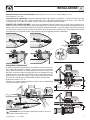
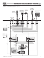
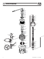
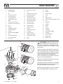
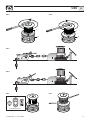
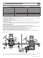
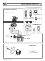
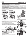
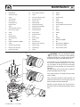
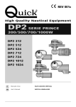
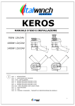
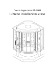
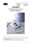
REV 000a
PRELIMINARE
PRELIMINARY
High Quality Nautical Equipment
XR7XROY SERIES
XR7
XR7
XR7
XR7
4024 DC
4000 AC
5500 AC
HYDRO
IT
Manuale d'uso
SALPA ANCORA VERTICALI
GB
User's Manual
VERTICAL WINDLASSES
IT
INDICE
Pag. 4
Pag. 5
Installazione
Pag. 6
Schema di collegamento XR7 4000W DC
Pag. 7
Pag. 8/9
Caratteristiche tecniche / Installazione
Schema di collegamento XR7 4000/5500W 400V AC
Manutenzione
Pag. 10
Avvertenze importanti - Uso
Pag. 11
Uso Pag.
12
Salpa ancora idraulico: caratteristiche tecniche - installazione
Pag.
13
Salpa ancora idraulico: schema di collegamento
GB
INDEX
Pag. 14
Technical data / Installation
Pag. 15
Installation
Pag. 16
Connection diagram XR7 4000W DC
Pag. 17 Connection diagram XR7 4000/5500W 400V AC
Pag. 1 8/19 Maintenance
Pag. 20
Warning - Usage
Pag. 21
Usage
Pag.
Hydraulic windlass: technical data - installation
22
Pag. 23
Hydraulic windlass: connection diagram
XR7 4000/5500/HY - IT GB - REV000A
3
CARATTERISTICHE TECNICHE - INSTALLAZIONE
IT
COME SI LEGGE IL MODELLO DEL SALPA ANCORA:
40
24
X
a
a
a
a
XR7
a
ESEMPIO: XR74024X
a
b
c
e
b
Nome della serie:
[ XR7 ] = base e campana in
acciaio inox AISI 316
c
Potenza motore:
[ 40 ] = 4000 W
[ 55 ] = 5500 W
MODELLO
POTENZA MOTORE
e
Tensione motore:
[ 24 ] = 24 V
[ TR ] = 230/400 V
Passacatena:
[ X ] = passacatena destro
[ Y ] = passacatena sinistro
XR7 4000 X/Y
4000 W
Tensione motore
24 V
Tiro istantaneo massimo
4000 Kg (8818 lb)
Carico di lavoro massimo
1500 Kg (3307 lb)
Carico di lavoro
700 Kg (1543 lb)
Assorbimento corrente al carico di lavoro (1)
190 A
Velocità massima di recupero (2)
29 m/min (95,1 ft/min)
Velocità di recupero al carico di lavoro (2)
15 m/min (49,2 ft/min)
Sezione minima cavi motore (3)
35 mm2 (AWG 2)
Interruttore di protezione (4)
40 A
Spessore coperta (5)
30 ÷ 60 mm (1” 3/16 ÷ 2” 5/16)
Peso
170 kg (375 lb)
MODELLI
POTENZA MOTORE
XR7 AC 4000 X/Y
4000 W TR
Tensione motore
Tiro istantaneo massimo
Carico di lavoro massimo
Velocità massima di recupero (2)
XR7 AC 5500 X/Y
5500 W TR
230/400 V
230/400 V
4000 Kg (8818 lb)
4500 Kg (8818 lb)
2000 Kg (4409 lb)
2350 Kg (5181 lb)
12,5 m/min (41 ft/min)
12,5 m/min (41 ft/min)
Spessore coperta (5)
30 ÷ 60 mm (1” 3/16 ÷ 2” 5/16)
Peso
180 kg (397 lb)
185 kg (408 lb)
• (1) Dopo un primo periodo d'uso. • (2) Misure effettuate con barbotin per catena da 14 mm. • (3) Valore minimo consigliato per una lunghezza totale L= <20m. Calcolare la
sezione del cavo in funzione della lunghezza del collegamento. • (4) Con interruttore specifico per correnti continue (DC) e ritardato (magneto-termico o magneto-idraulico).
• (5) Su richiesta possono essere forniti prigionieri per spessori di coperta maggiori.
BARBOTIN
12,5 mm
14 mm
16 mm
Catena supportata
12,5 mm
STUDLINK
14 mm
STUDLINK
16 mm
STUDLINK
INSTALLAZIONE
PRIMA DI UTILIZZARE IL SALPA ANCORA LEGGERE ATTENTAMENTE IL PRESENTE MANUALE D'USO.
IN CASO DI DUBBI CONSULTARE IL RIVENDITORE QUICK®.
ATTENZIONE: i salpa ancora Quick® sono stati progettati e realizzati per salpare l'ancora.
Non utilizzare questi apparecchi per altri tipi
Quick® non si assume alcuna responsabilità per i danni diretti o indiretti causati da un uso improprio dell'apparecchio.
di operazioni.
Il salpa ancora non è progettato per sostenere carichi generati in particolari condizioni atmosferiche (burrasca).
Disattivare sempre
Accertarsi che non vi siano bagnanti nelle vicinanze prima di calare l’ancora.
Per maggiore
il salpa ancora quando non è in uso.
Consigliasicurezza, nel caso in cui uno si danneggi suggeriamo di installare almeno due comandi per l’azionamento del salpa ancora.
mo l’uso dell’interruttore magneto-idraulico Quick® come sicurezza per il motore.
Bloccare la catena con un fermo prima di partire
La scatola teleinvertitori deve essere installata in un luogo protetto da possibili entrate d’acqua.
Dopo aver
per la navigazione.
Per prevenire rilasci non voluti l’ancora deve
completato l’ancoraggio, fissare la catena o cima a punti fissi quali chian stopper o bitta.
Isolare il salpa ancora dall’impianto elettrico durante
essere fissata, il salpa ancora non deve essere usato come unica presa di forza.
la navigazione (disinserire l’interruttore di protezione del motore) e bloccare la catena ad un punto fisso dell’imbarcazione.
LA CONFEZIONE CONTIENE: salpa ancora (top + motoriduttore) - cassetta teleinvertitori (XR7 4000W DC) - dima di foratura - leva viterie (per l'assemblaggio) - manuale di istruzioni - condizioni di garanzia.
F
Quick® si riserva il diritto di apportare modifiche alle caratteristiche tecniche dell'apparecchio e al contenuto di questo manuale senza alcun preavviso.
In caso di discordanze o eventuali errori tra il testo tradotto e quello originario in italiano, fare riferimento al testo italiano o inglese.
4
XR7 4000/5500/HY - IT GB - REV000A
INSTALLAZIONE
IT
ATTREZZI NECESSARI PER L'INSTALLAZIONE: trapano con punta: Ø 15 mm (19/32"); a tazza Ø 200 mm (7" 7/8);
chiave esagonale: 17 e 19 mm.
ACCESSORI QUICK® CONSIGLIATI: cassetta per collegamenti elettrici per motori AC (EC-Box40/55) - Comando da plancia (mod. 800)
- Pulsantiera stagna (mod. HRC 1002) - Pulsante a piede (mod. 915C) - Interruttore magneto-idraulico (mod. 10150) - Conta catena per
l'ancoraggio (mod. CHC 1102M e CHC 1202M) - Sistema di comando via radio RRC (mod. R02, P02, H02).
REQUISITI PER L'INSTALLAZIONE: il salpa ancora va posizionato allineando il barbotin con il puntale di prua. Verificare che le
superfici superiore e inferiore della coperta siano più parallele possibili; se ciò non dovesse accadere compensare opportunamente la
differenza (la mancanza di parallelismo potrebbe causare perdite di potenza del motore). Lo spessore di coperta dovrà essere compreso
fra i valori indicati in tabella. Se si avessero spessori differenti è necessario consultare il rivenditore Quick®. Non devono esistere ostacoli
sotto coperta per il passaggio della catena, la poca profondità del gavone potrebbe provocare inceppamenti.
max 5 mm
(3/16")
90°
90°
minimo
1m (39”3/8)
90°
RIFERIMENTO NUMERI A PAG. 8/9
PROCEDURA DI MONTAGGIO
A) stabilita la posizione ideale praticare i fori utilizzando la dima di foratura fornita a corredo. B) Rimuovere il materiale in eccesso dal foro di passaggio della
catena, rifinirlo e lisciarlo con un prodotto specifico (vernice marina, gel o resina
epossidica) assicurando il libero passaggio della catena. C) Posizionare la parte
superiore del salpa ancora. D Fissarlo avvitando i dadi sui prigionieri di bloccaggio. E) Inserire l’o-ring (38) nella flangia (42). F) Fissare la flangia all’inserto base
(35) tramite 6 viti (44). G) Inserire il motoriduttore nell’albero del salpa ancora.
H) Serrare con viterie (39 - 40 - 41).
Collegare i cavi di alimentazione provenienti dal salpa ancora al teleinvertitore
(DC) o all’alimentazione di rete (AC).
C
PRIGIONIERO (48)
RONDELLA (49)
GROWER (50)
DADO (51)
O-RING (38)
FLANGIA (42)
180 Nm
F
INSERTO
BASE (35)
D
E
VITE (44)
45°
A
B
VITE (39)
RONDELLA (40)
GROWER (41)
ATTENZIONE: prima di effettuare il collegamento accertarsi che non sia
presente l'alimentazione su cavi.
XR7 4000/5500/HY - IT GB - REV000A
H
G
5
SCHEMA DI COLLEGAMENTO
IT
SISTEMA BASE XR7 4000W DC
ACCESSORI QUICK® PER L'AZIONAMENTO
DEL SALPA ANCORA
PULSANTIERA
CONTACATENA
MOD. CHC 1102 M
PULSANTIERA
MULTIUSO
MOD. HRC 1002
COMANDO
DA PLANCIA
MOD. 800
CONTACATENA
DA PANNELLO
MOD. CHC 1202 M
RADIOCOMANDI RRC
TRASMETTITORI
SALPA ANCORA
RICEVITORE
MOD. R02
TASCABILE
MOD. P02
PULSANTIERA
MOD. H02
MOTORE
BLU
NERO
A1
A2
D1
D2
MARRONE
PULSANTI A PIEDE MOD. 915C
NERO
MARRONE
L5
BLU
BATTERIA
FUSIBILE
2A (24V)
L1
INTERRUTTORE
MAGNETO IDRAULICO
(vedi tabella pag.4)
L3
L2
L4
CASSETTA
TELEINVERTITORI
MOD. T6415-24 (24V)
L6
A2
C
A1
L = L1 + L2 + L3 + L4 + L5 + L6
6
XR7 4000/5500/HY - IT GB - REV000A
SCHEMA DI COLLEGAMENTO TRIFASE
IT
SISTEMA BASE XR7 4000/5500W 400V AC
CONTACATENA PER
ANCORAGGIO
MOD. CHC1202 M
PULSANTIERA
CONTACATENA
MOD. CHC1102 M
PULSANTIERA
MULTIUSO
MOD. HRC1002
COMANDO
DA PLANCIA
MOD. 800
RADIO RECEVITORE RRC
MOD. R02 (2CH)
PULSANTI A PIEDE
MOD. 915C
UP
+
-
DOWN
BLU
MARRONE
NERO
BLU
MARRONE
NERO
+
-
UP
DOWN
SENSORE
CAN L
CAN H
GRIGIO
ROSSO
VERDE
MARRONE
BIANCO
BLU
NERO
BLU
MARRONE
NERO
150
CAN L
CAN H
CAN L
CAN H
BATTERIA 24V
XP
T
L2
XP
S
L1
XP
R
FU1 8 -16A aM
T
FU1 8 -16A aM
S
FU1 8 -16A aM
R
KM1
24V
PE
V1
U1
24V
KM2
W1
L3
XP
R
XP
U1
S
XP
V1
T
XP
W1
SALPA ANCORA
SENSORE
W2
U2
V2
U1
V1
W1
MOTORE
400V CA Max
4,0KW / 5,5KW
M
1~
MORSETTIERA
XR7 4000/5500/HY - IT GB - REV000A
7
MANUTENZIONE
IT
1
2
3
4
5
6
32
7
33
34
34
8
35
9
10
36
11
12
13
19
20
14
21
22
23
24
26
15
25
25
31
16
27
29
29
30
37
37
34
34
17
18
28
33
32
48
49
50
51
8
XR7 4000/5500/HY - IT GB - REV000A
MANUTENZIONE
IT
N°.
DENOMINAZIONE
20
Staccacatena serie XR7
40
Grower
1
Leva in alluminio
21
Vite
41
Rondella
2
Vite
22
Supporto staccacatena XR7
42
Flangia riduttore
3
Bussola campana XR7
23
Perno ottone M16 XR7
43
O-ring
4
Disco campana XR7
24
Perno ottone XR7
44
Vite
5
Anello antirotazione
25
Anello elastico esterno
45
Riduttore TG130
6
Anello elastico esterno
26
Freno a fascia serie XR7
46
Flangia chiusura riduttore XR7 TG130
7
Molla
27
Volantino freno remoto
47
Vite
8
Campana salpa Ø 250 XR7
28
Asta freno remoto
48
Prigioniero
9
Distanziale disco campana XR7
29
Spina elastica dritta
49
Rondella
10
Vite
30
Giunto cardanico
50
Grower
11
Paraolio
31
Albero freno fascia
51
Dado
12
Anello elestico esterno
32
Paraolio
52
Chiavetta
13
Anello antirotazione
33
Anello elastico interno
53
Adattatore
14
Barbotin
34
Cuscinetto
54
Flangia Motore 3000W
15
Rondella di rinforzo 6000W
35
Inserto base XR7
55
Chiavetta
16
Vite
36
Albero salpa serie XR7
56
Motore 3000W 24V
17
Porta sensore cilindrico
37
Anello elastico esterno
57
Motore 4,0KW
18
Base salpa serie XR7
38
O-ring
58
Motore 5,5KW
19
Vite svasata
39
Vite
52
ATTENZIONE: accertarsi che non sia pre-
sente l'alimentazione al motore elettrico quando si opera manualmente sul salpa ancora; rimuovere con cura la catena o cima dal barbotin o la cima
dalla campana.
I salpa ancora Quick® sono costituiti da materiali resistenti all'ambiente marino: è indispensabile, in ogni
caso, rimuovere periodicamente i depositi di sale che
si formano sulle superfici esterne per evitare corrosioni e di conseguenza danni all'apparecchio.
Lavare accuratamente con acqua dolce le superfici e
le parti in cui il sale può depositarsi.
38
58
52
39
40
41
42
Smontare una volta all'anno il barbotin e la campana
attenendosi alla seguente sequenza:
43
Pulire ogni parte smontata affinché non si verifichino
attacchi di corrosione e ingrassare (con grasso marino) il filetto dell'albero (36) e il barbotin (14).
44
45
57
52
55
Rimuovere eventuali depositi di ossido sui morsetti
della cassetta teleinvertitori; cospargerli di grasso.
53
43
46
54
56
47
XR7 4000/5500/HY - IT GB - REV000A
9
IT
AVVERTENZE IMPORTANTI - USO
AVVERTENZE IMPORTANTI
ATTENZIONE: non avvicinare parti del corpo o oggetti alla zona in cui scorrono catena, cima e barbotin. Accertarsi che non sia
presente l'alimentazione al motore elettrico quando si opera manualmente sul salpa ancora (anche quando si utilizza la leva per
allentare la frizione); persone dotate di comando a distanza del salpa ancora (pulsantiera remota o radiocomando) potrebbero
accidentalmente attivarlo.
ATTENZIONE: bloccare la catena con un fermo prima di partire per la navigazione.
ATTENZIONE: non attivare elettricamente il salpa ancora con la leva inserita nella campana.
ATTENZIONE: Quick® consiglia di utilizzare una protezione tipo fusibile/magnetotermico/magnetoidraulico di potenza adeguata
a seconda del motore utilizzato per salvaguardare il motore da surriscaldamenti o corto-circuiti. L’interruttore può essere
utilizzato per isolare il circuito di comando del salpa ancora evitando così azionamenti accidentali.
USO
TRASMISSIONE DI POTENZA
L’asse centrale è connesso al riduttore e alla campana. Il barbotin viene trascinato dalla campana tramite innesti frontali sul barbotin.
Quando la campana (8) è alta (Fig. A) e la bussola (3) completamente svitata, il barbotin (14) è libero.
Quando la campana è bassa (Fig. B) e la bussola (3) completamente avvitata, il barbotin (14) è connesso all’asse tramite la campana e si
può salpare l’ancora.
INNESTO DEL BARBOTIN
1) Tramite la leva (1) avvitare ruotando in senso orario la bussola 3); la campana (8) si abbassa ingaggiando il barbotin (14).
La bussola non deve essere troppo stretta, in questo modo permetterà alla campana di ruotare sul barbotin e ingaggiare gli innesti
frontali tramite le molle (7).
2) Tramite la leva (1) svitare ruotando in senso antiorario la bussola di 1/4 di giro.
3) Rimuovere la leva.
4) Azionare il motore. Le molle (7) presenti nella bussola faranno ingaggiare gli innesti frontali tra campana e barbotin.
5) Assicurarsi visivamente dell’avvenuto innesto (Fig. B) e avvitare in senso orario la bussola.
6) Rimuovere la leva.
7) Allentare il freno a fascia (26) nel caso si debba utilizzare il salpa.
RECUPERO DELL’ANCORA CON MOTORE
1) Assicurarsi che la campana sia innestata al barbotin (Fig. B).
2) Agire sui comandi Quick® per salpare o rilasciare l’ancora.
CADUTA LIBERA (FREE FALL)
1) Assicurarsi che il chain stopper Quick® sia in posizione di NON blocco della catena (Fig. C).
2) Assicurarsi che il freno a fascia (26) sia completamente stretto.
3) Svitare in senso antiorario la bussola fino al suo fine corsa e assicurarsi che la campana sia alta, disinnestata dal barbotin (Fig. A).
4) Agire sul volantino per allentare il freno a fascia (26) e regolare la caduta libera (free fall) dell’ancora.
USO DELLA CAMPANA (BARBOTIN BLOCCATO)
1) Assicurarsi che il chain stopper Quick® sia in posizione di blocco della catena (Fig. D).
2) Assicurarsi che il freno a fascia (26) sia completamente stretto.
3) Svitare in senso antiorario la bussola fino al suo fine corsa e assicurarsi che la campana sia alta, disinnestata dal barbotin (Fig. A).
4) Agire sui comandi Quick® per far ruotare la campana in un senso o nell’altro (Fig. E). Avvolgere la cima alla campana in senso antio-
rario (almeno 3 giri - fig. F). La riduzione della velocità e della forza di recupero possono essere regolate facendo scorrere la cima sul
tamburo della campana.
ATTENZIONE: durante il recupero, mantenere un’adeguata distanza di sicurezza tra mani e campana salpa ancora.
10
XR7 4000/5500/HY - IT GB - REV000A
USO
IT
FIG. B
FIG. A
1
3
1
8
3
8
14
14
FIG. C
FIG. D
FIG. E
FIG. F
RADIOCOMANDI QUICK®
XR7 4000/5500/HY - IT GB - REV000A
11
SALPA ANCORA IDRAULICO
IT
MODELLO IDRAULICO
XR7 HYDRO X/Y
Tipologia motore
Reversibile ad ingranaggi
Cilindrata
22 cc
1,34 in3
• 100 bar = 1400 kg • 210 bar = 3000 kg
• 1450.4 psi = 3087 lb • 3045 psi = 6614 lb
50 lt /min = 12,5 mt/min
11,4 USG/min = 41 ft/min
30 ÷ 60 mm
1” 3/16 ÷ 2” 23/64 inch
165 kg
363,8 lb
Portata
50 lt/min
11,4 USG/min
Pressione massima
210 bar
3045 psi
Capacità di sollevamento
Velocità di recupero al carico di lavoro (1)
Spessore coperta (2)
Peso
VALORI DI REGOLAZIONE (consigliati da Quick)
(1) Misure effettuate con barbotin per catena da 14 mm.
(2) Su richiesta possono essere forniti prigionieri per spessori di coperta maggiori.
LA CONFEZIONE CONTIENE: salpa ancora idraulico (top + motoriduttore) - dima di foratura - leva - viterie (per l'assemblaggio) manuale di istruzioni - condizioni di garanzia.
ATTREZZI NECESSARI PER L'INSTALLAZIONE trapano con punta: Ø 15 mm (19/32"); a tazza Ø 200 mm (7" 7/8);
chiave esagonale: 17 e 19 mm.
ACCESSORI QUICK® CONSIGLIATI: comando da plancia (mod. 800) - Pulsantiera stagna (mod. HRC 1002) - Pulsante a piede (mod.
915C) - Conta catena per l'ancoraggio (mod. CHC 1102M e CHC 1202M) - Sistema di comando via radio RRC (mod. R02, P02, H02).
PROCEDURA DI MONTAGGIO
A) Stabilita la posizione ideale praticare i fori utilizzando la dima di foratura fornita a corredo (vedi figura pag. 5).
B) Rimuovere il materiale in eccesso dal foro di passaggio della catena, rifinirlo e lisciarlo con un prodotto specifico (vernice marina, gel
o resina epossidica) assicurando il libero passaggio della catena (vedi figura pag. 5).
C) Posizionare la parte superiore del salpa ancora, D) fissarlo avvitando i dadi sui prigionieri di bloccaggio.
E) Inserire l’o-ring (38) nella flangia (42). F) Fissare la flangia all’inserto base (35) tramite 6 viti (44).
G Inserire il motoriduttore nell’albero del salpa ancora. H) Serrare con viterie (39 - 40 - 41).
I) Collegare i tubi provenienti dalla valvola distributrice alle due flangette del motore idraulico (vedi schema di collegamento a pag.13).
RIFERIMENTO NUMERI A PAG. 8/9
C
PRIGIONIERO (48)
RONDELLA (49)
D
VITE (39)
RONDELLA (40)
GROWER (41)
GROWER (50)
180 Nm
DADO (51)
F
INSERTO
BASE (35)
VITE (44)
O-RING (38)
FLANGIA (42)
E
90°
G
90°
90°
90°
F
12
H
I
Quick® si riserva il diritto di apportare modifiche alle caratteristiche tecniche dell'apparecchio e al contenuto di questo manuale senza alcun preavviso.
In caso di discordanze o eventuali errori tra il testo tradotto e quello originario in italiano, fare riferimento al testo italiano o inglese.
XR7 4000/5500/HY - IT GB - REV000A
SALPA ANCORA IDRAULICO
IT
ACCESSORI QUICK® PER L’AZIONAMENTO
DEL SALPA ANCORA IDRAULICO
SISTEMA BASE XR7 IDRAULICO
SCHEMA DI COLLEGAMENTO
CONTACATENA DA PANNELLO
CHC 1202 M
PULSANTIERA
MULTIUSO
MOD. HRC 1002
PULSANTIERA
CONTACATENA
MOD. CHC 1002 M
COMANDO
DA PLANCIA
MOD.800
PULSANTI A PIEDE
MOD. 915 C
RADIOCOMANDI RRC
TRASMETTITORI
RICEVITORE
MOD. R02
TASCABILE
MOD. P02
PULSANTIERA
MOD. H02
VALVOLA
DISTRIBUTRICE
INGRESSO
PRESSIONE
SERBATOIO
MOTORE IDRAULICO
52
53
POS.
DENOMINAZIONE
52
Chiavetta
53
Adattatore
54
Flangia motore idraulico
59
Motore idraulico
60
Flangetta 90° G3/4 femmina
54
59
XR7 4000/5500/HY - IT GB - REV000A
60
13
TECHNICAL DATA
GB
HOW TO IDENTIFY THE WINDLASS THROUGH THE CODE:
40
24
X
a
a
a
a
XR7
a
EXAMPLE: XR74024X
a
b
c
e
b
Name of the line:
[ XR7 ] = stainless steel AISI 316
base and drum
c
Motor power:
[ 40 ] = 4000 W
[ 55 ] = 5500 W
MODEL
MOTOR POWER
e
Motor supply voltage:
[ 24 ] = 24 V
[ TR ] = 230/400 V
Chain pipe:
[ X ] = right chain pipe
[ Y ] = left chain pipe
XR7 4000 X/Y
4000 W
Motor supply voltage
24 V
Maximum pull
4000 Kg (8818 lb)
Maximum working load
1500 Kg (3307 lb)
Working load
700 Kg (1543 lb)
Current absorption @ working load (1)
190 A
Maximum chain speed (2)
29 m/min (95,1 ft/min)
Max. chain speed @ working load (2)
15 m/min (49,2 ft/min)
Motor cable size (3)
35 mm2 (AWG 2)
Protection circuit breaker (4)
40 A
Deck thickness (5)
30 ÷ 60 mm (1” 3/16 ÷ 2” 5/16)
Weight
170 kg (375 lb)
MODELS
MOTOR POWER
XR7 AC 4000 X/Y
4000 W TR
Motor supply voltage
Maximum pull
Maximum working load
Max. chain speed @ working load (2)
XR7 AC 5500 X/Y
5500 W TR
230/400 V
230/400 V
4000 Kg (8818 lb)
4500 Kg (8818 lb)
2000 Kg (4409 lb)
2350 Kg (5181 lb)
12,5 m/min (41 ft/min)
12,5 m/min (41 ft/min)
Deck thickness (5)
30 ÷ 60 mm (1” 3/16 ÷ 2” 5/16)
Weight
180 kg (397 lb)
185 kg (408 lb)
• (1) After an initial period of use. • (2) Measurements taken with a gypsy for a 14 mm chain. • (3) Minimum allowable value for a total length L<20m. Determine the cable size
according to the length of the wiring. • (4) With circuit breaker designed for direct currents (DC) and delayed-action (thermal-magnetic or hydraulic-magnetic). • (5) On request, studs can be supplied for greater deck thicknesses.
GYPSY
12,5 mm
14 mm
16 mm
Chain size
12,5 mm
STUDLINK
14 mm
STUDLINK
16 mm
STUDLINK
INSTALLATION
BEFORE USING THE WINDLASS READ THESE INSTRUCTIONS CAREFULLY.
IF IN DOUBT, CONTACT YOUR NEAREST “QUICK®” DEALER.
WARNING:the Quick® windlasses are designed to weigh the anchor.
Do not use the equipment for other purposes.
Quick® shall not be held responsible for damage to equipment and/or personal injury, caused by a faulty use of the equipment.
The windlass is not designed for the loads that might occur in extreme weather conditions (storms).
Always deactivate the
Check that there are no swimmers nearby before dropping anchor.
For improved safety we recomwindlass when not in use.
mend installing at least two anchor windlass controls in case one is accidentally damaged.
We recommend the use of the Quick®
Secure the chain with a further device before starting the navigation.
hydraulic-magnetic switch as the motor safety switch.
The reversing contactor unit must be installed in a point protected from accidental water contact.
After completing the anchorage, secure the chain or rope to fixed points such as chain stopper or bollard.
To prevent accidental releases, the anchor must be
Isolate the windlass from the power system during navigation
secured. The windlass shall not be used as the only securing device.
(switch the circuit breaker off) and lock the chain securing it to a fixed point of the boat.
THE PACKAGE CONTAINS: windlass (Top + motorgearbox) - reversing contactor unit (XR7 4000W DC) - drill template - handle - bolts
and screws (for assembly) - user’s manual - conditions of warranty.
F
14
Quick® reserves the right to introduce changes to the equipment and the contents of this manual without prior notice.
In case of discordance or errors in translation between the translated version and the original text in the Italian language, reference will be made to the Italian or English text.
XR7 4000/5500/HY - IT GB - REV000A
INSTALLATION
GB
TOOLS REQUIRED FOR INSTALLATION: drill and drill: Ø 15 mm (19/32”); hollow mill Ø 200 mm (7” 7/8);
chiave esagonale: 17 and 19 mm.
QUICK®”ACCESSORIES RECOMMENDED: electric connection box for AC motors (EC-Box40/55) - Windlass control board (mod. 800)
- Watertight hand helds R/C (mod. HRC1002) - Foot switch (mod. 915C) - Hydraulic-magnetic circuit breaker (mod. 10150) - Anchor chain
counter (mod. CHC1102M and CHC1202M) - RRC remote radio controls (mod. R02, P02, H02).
INSTALLATION REQUIREMENTS: the windlass must be positioned with the gypsy aligned with the bow roller. Ensure that the
upper and lower surfaces of the deck are as parallel as possible; If this is not the case, compensate the difference appropriately (a lack
of parallelism could result in a loss of motor power). The deck thickness must be included among the figures listed in the table. In cases
of other thicknesses it is necessary to consult a Quick® retailer. There must be no obstacles under deck to the passage of chain, lack of
depth of the peak could cause jamming.
max 5 mm
(3/16")
90°
90°
At least
1m (39”3/8)
90°
FOR THE NUMBERS, REFER TO PAGES 18/19
FITTING PROCEDURE
A) When the ideal position has been established, drill four holes using the drilling
template provided. B) Remove excess material from the chain passage, refine and
flatten with a specialized product (marine paint, gel coat or two pack epoxy) to
assure free passage for both chain. C) Place the upper section of the windlass.
D) Fasten it by screwing the nuts on the fixing stud bolts.
E) Fit the O-ring (38) in the flange (42). F) Fasten the flange to the base insert (35)
using the 6 screws (44). G) Fit the motorgearbox to the windlass shaft.
H) Tighten with the set of screws (39 - 40 - 41).
Connect the supply cables from the windlass to the reversing contactor unit (DC)
or to the mains (AC).
C
3
STUD (48)
WASHER (49)
GROWER (50)
NUT (51)
O-RING (38)
FLANGE (42)
180 Nm
F
BASE
INSERT (35)
D
E
SCREW (44)
45°
A
B
SCREW (39)
WASHER (40)
GROWER (41)
WARNING: before wiring up, be sure the electrical cables are not live.
XR7 4000/5500/HY - IT GB - REV000A
H
G
15
GB
CONNECTION DIAGRAM
BASIC SYSTEM XR7 4000W DC
QUICK® ACCESSORIES
FOR WIN DLASS OPERATION
WATERTIGHT HAND HELD
CHAIN COUNTER
MOD. CHC 1102 M
MULTI-PURPOSE
WATERTIGHT HAND HELD
REMOTE CONTROL
MOD. HRC 1002
WINDLASS
CONTROL BOARD
MOD. 800
WATERTIGHT
PANEL
CHAIN COUNTER
MOD. CHC 1202 M
REMOTE RADIO CONTROLS RRC
TRANSMITTERS
WINDLASS
RECEIVER
MOD. R02
RADIO POCKET
MOD. P02
HANDHELD
MOD. H02
MOTOR
BLUE
BLACK
A1
A2
D1
D2
BROWN
FOOT SWITCHES MOD. 915C
BLACK
BROWN
L5
BLUE
BATTERY
FUSE
2A (24V)
L1
HYDRAULIC-MAGNETIC
CIRCUIT BREAKER
(SEE TABLE ON PAGE 14)
L3
L2
L4
REVERSING
CONTACTOR UNIT
MOD. T6415-24 (24V)
L6
A2
C
A1
L = L1 + L2 + L3 + L4 + L5 + L6
16
XR7 4000/5500/HY - IT GB - REV000A
CONNECTION DIAGRAM
GB
BASIC SYSTEM XR7 4000/5500W 400V AC
WATERTIGHT
HAND HELD
CHAIN-COUNTER
MOD. CHC1102 M
WATERTIGHT PANEL
CHAIN-COUNTER
MOD. CHC1202 M
WINDLASS
CONTROL BOARD
MOD. 800
MULTI-PURPOSE
WATERTIGH HAND HELD
REMOTE CONTROL
MOD. HRC1002
RADIO RECEIVER RRC
MOD. R02 (2CH)
FOOT SWITCHES
MOD. 915C
UP
+
-
DOWN
BLUE
BROWN
BLACK
BLUE
BROWN
BLACK
+
-
UP
DOWN
SENSOR
CAN L
CAN H
GREY
RED
GREEN
BROWN
WHITE
BLUE
BLACK
BLUE
BROWN
BLACK
150
CAN L
CAN H
CAN L
CAN H
BATTERY 24V
XP
T
L2
XP
S
L1
XP
R
FU1 8 -16A aM
T
FU1 8 -16A aM
S
FU1 8 -16A aM
R
KM1
24V
PE
V1
U1
24V
KM2
W1
L3
XP
R
XP
U1
S
XP
V1
T
XP
W1
WINDLASS
SENSOR
MOTOR
400V CA Max
4,0KW / 5,5KW
W2
U2
V2
U1
V1
W1
M
1~
TERMINAL BOARD
XR7 4000/5500/HY - IT GB - REV000A
17
GB
MAINTENANCE
1
2
3
4
5
6
32
7
33
34
34
8
35
9
10
36
11
12
13
19
20
14
21
22
23
24
26
15
25
25
31
16
27
29
29
30
37
37
34
34
17
18
28
33
32
48
49
50
51
18
XR7 4000/5500/HY - IT GB - REV000A
MAINTENANCE
GB
N.
DESCRIPTION
20
Chain stripper series XR7
40
Grower
1
Aluminium handle
21
Screw
41
Washer
2
Screw
22
XR7 chain stripper support
42
Gearbox flange
3
XR7 drum bush
23
XR7 M16 brass pin
43
O-ring
4
XR7 drum disc
24
XR7 brass pin
44
Screw
5
Anti-rotation ring
25
External circlip
45
TG130 Gearbox
6
External circlip
26
XR7 brake band series
46
XR7 TG130 gearbox closing flange
7
Spring
27
Remote brake handwheel
47
Screw
8
XR7 drum windlass Ø 250
28
Remote brake rod
48
Stud
9
XR7 drum disc spacer
29
Straight spring pin
49
Washer
10
Screw
30
Universal joint
50
Grower
11
Oil seal
31
Band brake shaft
51
Nut
12
External circlip
32
Oil seal
52
Key
13
Anti-rotation ring
33
Internal circlip
53
Adapter
14
Gypsy
34
Bearing
54
Motor flange 3000W
15
Washer reinforcement 6000W
35
XR7 base insert
55
Key
16
Screw
36
Windlass shaft series XR7
56
Electrical motor 3000W 24V
17
Cylindrical sensor holder
37
External circlip
57
Electrical motor 4,0KW
18
Windlass base series XR7
38
Cylindrical pin
58
Electrical motor 5,5KW
19
Countersunk screw
39
Screw
52
WARNING: make sure the electrical power
to the motor is switched off when working
manually on the windlass. Carefully remove the chain
or rope from the gypsy or the rope from the drum.
Quick® windlasses are manufactured with materials resistant to marine environments. In any case,
any salt deposits on the outside must be removed
periodically to avoid corrosion and damage to the
equipment.
The parts where salt may have built up should be
washed thoroughly with fresh water.
38
58
52
39
40
41
Once a year, the drum and the gypsy are to be taken
apart as follows:
42
43
Clean all the parts removed to avoid corrosion, and
grease the shaft thread (36) and the gypsy (14) (use
grease suitable for marine environment).
44
45
57
52
55
Remove any oxide deposits from the terminals of
the electric motor and the reversing solenoid; grease
them.
53
43
46
54
56
47
XR7 4000/5500/HY - IT GB - REV000A
19
GB
WARNING - USAGE
WARNING
WARNING: stay clear of the chains, ropes and gypsy. Make sure the electric motor is off when windlass is used manually (even
when using the handle to disengage the clutch). In fact people with windlass remote controls (hand-held remote control or radio-controlled systems) might accidentally operate it.
WARNING: secure the chain with a device before starting the navigation.
WARNING: do not operate the windlass by using the electrical power when the handle is inserted in the drum or into the gypsy
cover.
WARNING: Quick® suggests the use of a protection such as a fuse/thermal-magnetic/ hydraulic-magnetic circuit breaker of
suitable power according to the motor chosen, in order to protect it from any overheating or short circuits. The circuit breaker can
be used to cut off power to the windlass control circuit and so avoid accidental activation.
USAGE
POWER TRANSMISSION
The main axis is linked to the reduction unit and the drum. The gypsy is pulled by the drum via front couplings found on the gypsy.
When the drum (8) is up (Fig. A) and the bush (3) is fully unscrewed, the gypsy (14) is free.
When the drum is down (Fig. B) and the bush (3) is fully screwed, the gypsy (14) is linked to the axis by means of the drum and the anchor
can be weighed.
GYPSY CONNECTION
1) Turn and screw bush (3) clockwise by means of lever (1); the drum (8) goes down and so the gypsy (14) is coupled.
The bush should not be too tight; in this way it will let the drum turn on the gypsy and engage the front couplings by means of the
springs (7).
2) Turn and unscrew the bush by a ¼ of a turn anti-clockwise, using lever (1).
3) Remove the lever.
4) Start the motor. The springs (7) in the bush will cause the front couplings between the drum and the gypsy to engage.
5) A thorough visual inspection will confirm whether the coupling is successful or not (Fig. B). Turn and screw the bush clockwise.
6) Remove the lever.
7) Slacken the belt brake (26) should you need to use the windlass.
ANCHOR WEIGHING USING MOTOR
1) Make sure that the drum is coupled to the gypsy (Fig. B).
2) Operate the Quick® controls to weigh or drop the anchor.
FREE FALL
1) Make sure that the Quick® chain stopper is at a position that does NOT block the chain (Fig. C).
2) Make sure that the band brake (26) is completely tight.
3) Unscrew the bush counter clockwise up to the end of stroke and make sure that the drum is up, not engaged to the gypsy (Fig. A).
4) Operate the handwheel to loosen the band brake (26) and adjust the free fall of the anchor.
USING THE DRUM (GYPSY LOCKED)
1) Make sure that the Quick® chain stopper is at a position blocking the chain (Fig. D).
2) Make sure that the band brake (26) is completely tight.
3) Unscrew the bush counter-clockwise up to the end of stroke and make sure that the drum is up, not engaged to the gypsy (Fig. A).
4) Operate the Quick® controls to make the drum turn to one side or the other (Fig. E). Wrap the rope around the drum anti-clockwise (3
turns at least - Fig. F). Adjust the reduction of both weighing speed and power by letting the rope slide on the drum cylinder.
WARNING: during take up maintain a safe distance between hands and windlass drum.
20
XR7 4000/5500/HY - IT GB - REV000A
USAGE
GB
FIG. B
FIG. A
1
3
1
8
3
8
14
14
FIG. C
FIG. D
FIG. E
FIG. F
QUICK® RADIO REMOTE CONTROL
XR7 4000/5500/HY - IT GB - REV000A
21
HYDRAULIC WINDLASS
GB
HYDRAULIC MODEL
XR7 HYDRO X/Y
Motor type
Reversible gear-type
Motor power
22 cc
1,34 in3
• 100 bar = 1400 kg • 210 bar = 3000 kg
• 1450.4 psi = 3087 lb • 3045 psi = 6614 lb
50 lt /min = 12,5 mt/min
11,4 USG/min = 41 ft/min
30 ÷ 60 mm
1” 3/16 ÷ 2” 23/64 inch
165 kg
363,8 lb
Flow rate
50 lt/min
11,4 USG/min
Maximum pression
210 bar
3045 psi
Lifting capacity
Max. chain speed @ working load (1)
Deck thickness (2)
Weight
SETTING VALUES (suggested by Quick)
(1) Measurements taken with a gypsy for a 14 mm chain.
(2) On request, studs can be supplied for greater deck thicknesses.
THE PACKAGE CONTAINS: hydraulic windlass (top + motorgearbox) - drill template - handle - bolts and screws (for assembly) - user’s
manual - conditions of warranty.
TOOLS REQUIRED FOR INSTALLATION: drill and drill bits: Ø 15 mm (19/32”); hollow mill Ø 200 mm (7” 7/8);
hexagonal wrench: 17 e 19 mm.
“QUICK®”ACCESSORIES RECOMMENDED: windlass control board (mod. 800) - Watertight hand helds R/C (mod. HRC1002) - Foot
switch (mod. 915C) - Anchor chain counter (mod. CHC1102M and CHC1202M) - RRC remote radio control (mod. R02, P02, H02).
FITTING PROCEDURE
A) When the ideal position has been established, drill four holes using the drilling template provided (see figure on page 5).
B) Remove excess material from the chain passage, refine and flatten with a specialized product (marine paint, gel coat or two pack
epoxy) to assure free passage for both chain (see figure on page 5).
C) Place the upper section of the windlass, D) Fasten it by screwing the nuts on the fixing stud bolts.
E) Fit the O-ring (38) in the flange (42). F) Fasten the flange to the base insert (35) using the 6 screws (44).
G) Fit the motorgearbox to the windlass shaft. H) Tighten with the set of screws (39 - 40 - 41).
I) Connect the hoses deriving from the selector valve to the flanges of the hydraulic motor (see connection diagram on page 23).
FOR THE NUMBERS, REFER TO PAGES 18/19
C
STUD (48)
WASHER (49)
GROWER (50)
180 Nm
D
SCREW (39)
WASHER (40)
GROWER (41)
NUT (51)
F
BASE
INSERT (35)
SCREW (44)
O-RING (38)
FLANGE (42)
E
90°
G
90°
90°
90°
F
22
H
I
Quick® reserves the right to introduce changes to the equipment and the contents of this manual without prior notice.
In case of discordance or errors in translation between the translated version and the original text in the Italian language, reference will be made to the Italian or English text.
XR7 4000/5500/HY - IT GB - REV000A
HYDRAULIC WINDLASS
BASIC SYSTEM HYDRAULIC XR7
GB
QUICK® ACCESSORIES
FOR HYDRAULIC WINDLASS OPERATION
CONNECTION DIAGRAM
WATERTIGHT PANEL
CHAIN COUNTER
MOD. CHC 1202 M
MULTI-PURPOSE
WATERTIGH
HAND HELD
REMOTE CONTROL
MOD. HRC 1002
WATERTIGHT
HAND HELD
CHAIN COUNTER
MOD. CHC 1102M
WINDLASS
CONTROL
BOARD
MOD. 800
FOOT SWITCHES
MOD. 915 C
REMOTE RADIO CONTROLS RRC
TRANSMITTER
RECEIVER
MOD. R02
RADIO POCKET
MOD. P02
HANDHELD
MOD. H02
SELECTOR
VALVE
PRESSURE
INPUT
TANK
HYDRAULIC MOTOR
52
53
N.
DESCRIPTION
52
Key
53
Adapter
54
Flange
59
Hydraulic motor
60
Flange 90° G3/4 female
54
59
XR7 4000/5500/HY - IT GB - REV000A
60
23
XR7 - DIMENSIONI / DIMENSIONS mm (inch)
383 (15 5/74)
318 (12 33/64)
378 (14 7/8)
XR7 4000W DC
710 (27 61/64)
400 (15 3/4)
Ø 295 (11 39/64)
255 (10 3/64)
Ø 250 (9 27/32)
663 (26 7/64)
24
XR7 4000/5500/HY - IT GB - REV000A
XR7 - DIMENSIONI / DIMENSIONS mm (inch)
383 (15 5/74)
318 (12 33/64)
378 (14 7/8)
XR7 4000/5000W AC
710 (27 61/64)
400 (15 3/4)
Ø 295 (11 39/64)
270 (10 5/8)
Ø 250 (9 27/32)
661 (26 1/64)
XR7 4000/5500/HY - IT GB - REV000A
25
XR7 - DIMENSIONI / DIMENSIONS mm (inch)
383 (15 5/74)
318 (12 33/64)
378 (14 7/8)
XR7 HYDRO
710 (27 61/64)
400 (15 3/4)
Ø 295 (11 39/64)
255 (10 1/32)
Ø 250 (9 27/32)
481 (18 15/16)
NOTES
XR7 XROY SERIES
R000a
4000DC / 4000AC / 5500AC / HYDRO
IT
Codice e numero seriale del prodotto
GB
Product code and serial number
QUICK® S.P.A. - Via Piangipane, 120/A - 48124 Piangipane (RAVENNA) - ITALY
Tel. +39.0544.415061 - Fax +39.0544.415047
www.quickitaly.com - E-mail: [email protected]