1
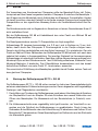
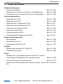
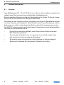
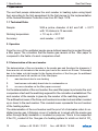
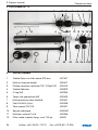
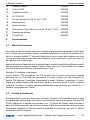
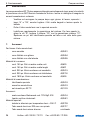
Rußtestpumpe RP 72
TÜV 12 RgG 015
Rußtestpumpe RG 68
13.12.2007 Art. Nr. 20778
Inhalt
1. Spezifikation............................................. 2
5. Betrieb....................................................... 6
2. Handhabung............................................ 3
6. Wartung..................................................... 6
3. Ersatzteilfoto............................................. 4
7. Zubehör und Optionen......................... 7
4. Ersatzteilliste............................................ 5
8. Garantie und Service............................ 8
Technik nach Maß
1. Spezifikation
1.
Rußtestpumpe
Spezifikation
Die Wöhler Rußtestpumpen RP 72 + RG 68 dienen der Bestimmung der Rußzahl bei Feuerungsanlagen für flüssige Brennstoffe entsprechend der Ersten Verordnung zur Durchführung des Bundesimmissionsschutzgesetzes 1.BImSchV vom 1. November 1996.
1.1.
Technische Daten
Durchsatz:
Bei einem Sondeninnendurchmesser von 6,0 mm
1,63 ± 0,07 Liter bei 10 Hüben in 60 sec.
Arbeitstemperatur:
+ 10 ..... + 30 °C
Genauigkeit:
Rußzahl ± 0,2 RZ
2.
Handhabung
Aus dem Kern des unverdünnten Abgases wird eine definierte Probe durch ein Filterpapier gesaugt. Der Schwärzungsgrad des auf dem Filterpapier abgebildeten Rußfleck
wird mit den Schwärzungsfeldern einer Rußzahlvergleichsskala verglichen und mit einer
Rußzahl bewertet.
2.1.
Ermittlung der Rußzahl
Die Ermittlung der Rußzahl der Abgase und die anschließende Feststellung, ob sich Ölderivate im Rauchgas befinden, sind insgesamt dreimal vorzunehmen. Für jeden Durchgang
sind 10 Pumpenhübe erforderlich. Die Probe ist rechtwinklig zum Abgasstrom zu entnehmen. Eine weitere Messung ist durchzuführen, wenn das beaufschlagte Filterpapier
1. durch Überhitzung verfärbt wurde,
2. durch Kondensatbildung merklich feucht wurde, oder
3. keinen gleichmäßigen Schwärzungsgrad über den Querschnitt des Rußflecks aufweist.
Zur Bestimmung der Rußzahl ist das beaufschlagte Filterpapier unter die Ausschnitte der Rußzahlvergleichsskala zu legen und das dem Schwärzungsgrad
entsprechende Feld nach dem Augenschein festzustellen. Die Rußzahl der
Probe ist durch die Nummer dieses Feldes gegeben.
Aus den drei Rußzahlen ist der arithmetische Mittelwert zu bilden und auf die
nächste Zahl auf- bzw. abzurunden. Dieser gerundete Mittelwert stellt die Rußzahl der Anlage dar.
Die Rußzahlbestimmung und der Nachweis der Ölderivate beziehen sich auf
das unverdünnte Abgas.
2
Hotline: 0 29 53 / 73 211
Fax: 0 29 53 / 73 250
Rußtestpumpe
1. Handhabung
Ausführlich beschrieben und erläutert ist das Verfahren in der DIN 51402 T1 vom Oktober
1986.
2.1. Funktionskontrolle der Rußtestpumpen RP 72 + RG 68
2.1.1 Messkopf und Sonde
Die Messköpfe müssen sauber sein. Die seitlichen Klammern sollen beide Messköpfe
gasdicht zusammenhalten.
Die Stopfentülle am Wasserfänger des Messkopf-Makrolon muss mit einem O-Ring abgedichtet sein, ebenso die Stopfen am Ventildeckel.
Zur direkten Funktionskontrolle kann die Sonde mit der Spitze in Wasser gehalten und die vorher herausgezogene Kolbenstange in die Pumpe hineingedrückt werden. Hierbei dürfen aus der Sondenspitze keine Luftblasen austreten.
Das Ventilplättchen 13 darf nicht verformt sein und muss mit der Wulstseite auf
der Edelstahlfeder 11 aufliegen. Beide Teile sollen frei und nicht verkantet in
der Ventilaufnahme 23 stehen.
2.1.2. Dichtheit der Pumpe
Grundvoraussetzung für den ordnungsgemäßen Rußtest ist die Dichtheit der Rußtestpumpen.
Zur Dichtheitskontrolle wird das Sondenrohr zugehalten und die Kolbenstange bis zum
Anschlag herausgezogen. Nach einer Wartezeit von ca. 3 Sekunden zum Druckausgleich
muss die Kolbenstange fast komplett in die Pumpe zurückschnellen. Nach wiederholtem
Herausziehen schnellt die Kolbenstange einer dichten Pumpe komplett zurück und schlägt
auf dem Anschlag auf.
Ist dies nicht der Fall, folgende Punkte kontrollieren:
• Kontrolle der Dichtungsringe:
- an der Stopfentülle 6 und dem Stopfen 25 (Runddichtring 5)
- am Ventildeckel 15 (Runddichtring 14)
- an der Ventilaufnahme 24 (Runddichtring 22)
• Kontrolle der Manschette an der Kolbenstange:
- Die Dichtungslippe der Manschette 21 auf der Kolbenstange darf keine Verletzung
aufweisen, ansonsten muss die Manschette ersetzt werden.
e-mail: [email protected]
Internet: http://mgkg.woehler.de
3
3. Ersatzteilfoto
3.
Rußtestpumpe
1
Ersatzteilfotos RP 72 + RG 68
9
8
10
3
4
5
6
7
11 12 13 14 15 16
8
8
17
2
8
18
19
20
21
22
23
24 25 4 6 26
Abbildung 3.1: Ersatzteile RP 72 und RG 68 P
27
29
28
30
32
4
33
31
34
35
Hotline: 0 29 53 / 73 211
Abbildung 3.2: Ersatzteile Hubzählwerk RG 68
Fax: 0 29 53 / 73 250
Rußtestpumpe
4. Ersatzteilliste
4. Ersatzteile Rußtestpumpe RP 72 + RG 68 inkl. Hubzählwerk
•
•
•
•
•
•
•
•
•
•
•
•
•
•
•
•
•
•
•
•
•
•
•
•
•
•
•
•
•
•
•
•
•
•
•
•
•
•
•
1 Messkopf-Ryton mit Sondenrohr 200 mm
Best.-Nr. 7547
2 Klammern
Best.-Nr. 30235
3 Filterpapier TÜV 12 RgG 001
s. Zubehör
4 Messkopf-Makrolon
Best.-Nr. 3879
5 Runddichtring 9 x 2
Best.-Nr. 2334
6 Stopfentülle mit Dichtring 9 x 2
Best.-Nr. 2442
7 Schutzfeder
Best.-Nr. 2441
8 RG 68: Schraube M 5 x 10 (2 St.)
Best.-Nr. 2439
8 RG 68: Schraube M 4,2 x 9,5 (2 St.)
Best.-Nr. 2428
8 RP 72: Schraube M 4,2 x 9,5 (4 St.)
Best.-Nr. 2428
9 RG 68: Pumpenrohr TÜV 014
Best.-Nr. 2417
9 RP 72: Pumpenrohr TÜV 015
Best.-Nr. 2427
10 Turbulenzspirale
Best.-Nr. 20401
11 Feder für Ventil 11 x 0,4
Best.-Nr. 2346
12 Watterollen lang (2 St.)
s. Zubehör
13 Ventilplättchen
Best.-Nr. 2345
14 Runddichtring 18 x 2,2
Best.-Nr. 2434
15 Ventildeckel
Best.-Nr. 7997
16 Schrauben 3/16“ x 20
Best.-Nr. 2435
17 Pumpenknopf (ab 01.01.03 mit Gewinde M 12)
Best.-Nr. 2420
18 Kolbenführung (nicht bei RG 68)
Best.-Nr. 2459
19 Alu-Scheibe
Best.-Nr. 2424
20 RG 68: Kolbenstange, Alu 300 mm
Best.-Nr. 2421
20 RP 72: Kolbenst., Ryton 255 mm (M 12 ab 01.01.03)Best.-Nr. 3878
21 Manschette
Best.-Nr. 2423
22 Runddichtring 30 x 3
Best.-Nr. 2430
23 Ventilaufnahme
Best.-Nr. 2429
24 Watterolle kurz (1 St.)
s. Zubehör
25 Stopfen (2 St.)
Best.-Nr. 2438
26 Messgeräte-Schlauch, 1 m
Best.-Nr. 2338
27 Stellring
Best.-Nr. 2425
28 Gewindestift M 6 x 10
Best.-Nr. 2426
29 Zählrad
Best.-Nr. 2456
30 Federstange
Best.-Nr. 2454
31 Sperrfeder
Best.-Nr. 2455
32 Deckel
Best.-Nr. 2452
33 Schraube M 4 x 8 (2 St.)
Best.-Nr. 2327
34 Schraube M 4,2 x 16
Best.-Nr. 2457
35 Zählgehäuse
Best.-Nr. 2451
e-mail: [email protected]
Internet: http://mgkg.woehler.de
5
5. Betrieb und Wartung
5.
Rußtestpumpe
Betrieb
Zur Vermeidung von Kondensat am Filterpapier sollte der Messkopf-Ryton inkl. Turbulenzspirale auf dem Kessel vorgewärmt werden. Filterpapier 3 zwischen die Messköpfe 1
und 4 legen und die Messköpfe durch Aufdrücken der Klammern 2 verschließen. Hierbei
ist darauf zu achten, dass der Kerbstift in die Kerbe einrastet. Einige schnell ausgeführte
Pumpenhübe vor der eigentlichen Messung fördern die Funktionsbereitschaft des Gerätes.
Die Entnahmesonde wird im Abgasrohr im Kernstrom mit einem Gewindekonus 8 mm Ø
dicht schließend fixiert.
Bei der Rußtestpumpe RG 68 mit Hubzählwerk den roten Punkt vom Zählrad 28 auf
Anfangstellung einstellen.
Zur Rauchgasentnahme werden 10 Pumpenhübe wie folgt ausgeführt:
Kolbenstange 20 langsam herausziehen (ca. 2-3 sec.) und in Endlage ca. 3 sec. festhalten, damit durch das Filterpapier 3 Druckausgleich in der Pumpe erfolgen kann.
Danach den Kolben zurückstoßen und den Ablauf insgesamt 10 x wiederholen. Der rote
Punkt am Zählrad 28 des Zählwerkes der Rußtestpumpe RG 68 befindet sich nach dem
zehnten Hub wieder in Ausgangsstellung. Die jeweilige Wartezeit bei herausgezogener
Kolbenstange ist unbedingt einzuhalten, damit das richtige Abgasvolumen gezogen wird.
Messkopf-Ryton mit der Entnahmesonde 1 der Prüföffnung entnehmen, Klammern 2 vom
Messkopf-Makrolon 4 abstreifen. Das Filterplättchen herausnehmen und den darauf
befindlichen Rußfleck, wie unter Punkt 2.1. beschrieben, auswerten.
Die exzentrische Prüföffnung des Messkopfes gestattet durch Drehen weitere Tests mit
dem gleichen Filterpapier.
6.
Wartung der Rußtestpumpen RP 72 + RG 68
Die Rußtestpumpen RP 72 + RG 68 sollen zweimal im Jahr einer Genauigkeitskontrolle
auf einem anerkannten Prüfstand unterzogen werden. Davon abgesehen sind regelmäßige
Wartungs- und Pflegearbeiten unerlässlich:
1. Durchlüften und Trocknen der Rußtestpumpen nach jedem Arbeitstag durch Abziehen
der Stopfentülle 6 und der Stopfen 25 sowie Entnahme der nassen Watterollen und
Öffnen des Messkopfes. Die Messsonde mit der Sondenbürste (s. Zubehör) reinigen.
2. Die Kolbenmanschette muss regelmäßig leicht geölt werden, um Verschleiß zu vermeiden und die Dichtheit der Rußtestpumpen zu gewährleisten. Durch Lösen der
Schrauben 8 des Zählwerks oder die Kolbenführung 18 abnehmen und Kolben 20 mit
Manschette 21 herausziehen. Etwas Spezialpflegeöl auf Kolbenrohr und die Rückseite
der Manschette geben.
6
Hotline: 0 29 53 / 73 211
Fax: 0 29 53 / 73 250
Rußtestpumpe
7. Zubehör und Optionen
7.
Zubehör und Optionen
Sondenbefestigungen:
• Schwenksondenhalter
Best.-Nr. 2491
•
Klemmkonus zur Fixierung der Sonde in der Messöffnung
Best.-Nr. 2494
•
Gewindekonus zur Fixierung der Sonde in der Messöffnung
Best.-Nr. 2495
Verbrauchsmaterialien:
•
Watterollen kurz, 25 St.
Best.-Nr. 1006
•
Watterollen lang, 50 St.
Best.-Nr. 2450
•
Watterollen kurz, Großpackung 150 St.
Best.-Nr. 620
•
Watterollen lang, Großpackung 150 St.
Best.-Nr. 621
•
Filterpapier Klarsichtdose, 300 St.
Best.-Nr. 2414
•
Filterpapier Beutel, 300 St.
Best.-Nr. 2415
•
Filterpapierspender, 300 St.
Best.-Nr. 3700
•
Filterpapier Beutel, Großpackung 1800 St.
Best.-Nr. 590
Pflege und Wartungsartikel:
•
Spezialpflegeöl
Best.-Nr. 2418
•
Sondenbürste 6 mm Ø
Best.-Nr. 2419
•
Ersatzteilbeutel RG 68 / RP 72
Best.-Nr. 1076
Zubehör:
•
Rußzahlvergleichsskala TÜV 12 RgG 018
Best.-Nr. 2416
•
Öltestflasche mit Aceton
Best.-Nr. 2481
Option:
•
Messkopf Alu 4, bei Abgastemperaturen über 250 °C und bei
Verwendung mit Entnahmesonden besonderer Länge
Best.-Nr. 2728
•
VA Sonde 220 mm mit Turbulenzspirale
Best.-Nr. 2727
•
Falls Sie eine VA Sonde besonderer Länge benötigen, wenden Sie sich bitte an
uns.
e-mail: [email protected]
Internet: http://mgkg.woehler.de
7
8. Garantie und Service
8.
Garantie und Service
8.1
Garantie
Rußtestpumpe
Jede Rußtestpumpe RZ 72 und RG 68 wird im Werk in allen Funktionen geprüft und
verlässt unser Werk erst nach einer ausführlichen Qualitätskontrolle.
Bei sachgemäßem Gebrauch beträgt die Garantiezeit auf die Pumpe 12 Monate. Ausgenommen sind Verschleißteile und Verbrauchsmaterialien.
Die Kosten für den Transport und die Verpackung der Pumpe im Reparaturfall werden
von dieser Garantie nicht abgedeckt. Diese Garantie erlischt, wenn Reparaturen und Abänderungen von dritter, nicht autorisierter Stelle an dem Gerät vorgenommen wurden.
Der SERVICE wird bei uns sehr groß geschrieben. Deshalb sind wir auch selbstverständlich nach der Garantiezeit für Sie da.
•
Es erfolgt eine sofortige Reparatur, wenn Sie mit Ihrem Gerät zu uns nach
Bad Wünnenberg kommen.
•
Sie schicken das Gerät zu uns, wir reparieren es innerhalb weniger Tage,
und schicken es Ihnen mit unserem Paketdienst.
•
Sie erhalten gegen einen geringen Pauschalbetrag ein Leihgerät gestellt.
•
Sofortige Hilfe erhalten Sie durch unsere Techniker am Telefon. 8
Hotline: 0 29 53 / 73 211
Fax: 0 29 53 / 73 250
8. Garantie und Service
Rußtestpumpe
8.2 Verkaufs- und Servicestellen
Deutschland:
Wöhler Messgeräte Kehrgeräte GmbH
Schützenstr. 41
33181 Bad Wünnenberg
Tel.: +49 29 53 / 73 - 211
Fax: +49 29 53 / 73 - 250
e-mail: [email protected]
http://mgkg.woehler.de
Niederbayern-Oberpfalz
Reinhilde Ortner
St.-Erasmus-Str. 5
94469 Deggendorf/Deggenau
Tel.: +49 9 91 / 3 70 85 - 0
Fax: +49 9 91 / 3 70 85 - 16
Verkaufs- und Servicestelle Rhein/Ruhr
Wöhler Messgeräte Kehrgeräte GmbH
Castroper Str. 105
44791 Bochum
Tel.: +49 2 34 / 51 69 93 - 0
Fax: +49 2 34 / 51 69 93 - 99
e-mail: [email protected]
Berlin
Catrin Kortze
Löwestr. 18
10249 Berlin
Tel.: +49 30 / 42 65 102 - 720
Fax : +49 30 / 42 65 102
Verkaufs- und Servicestelle Süd
Wöhler Messgeräte Kehrgeräte GmbH
Gneisenaustr.12
80992 München
Tel.: +49 89 / 15 89 223 - 0
Fax: +49 89 / 15 89 223 - 99
e-mail: [email protected]
e-mail: [email protected]
Internet: http://mgkg.woehler.de
9
8. Garantie und Service
Rußtestpumpe
Im europäischen Ausland:
Czech Republic
Wöhler Bohemia s.r.o.
Za Naspem 1993
393 01 Pelhrimov
Tel.: +420 56 53 49 019
Fax: +420 56 53 23 078
e-mail: [email protected]
Italy
Wöhler Italia srl
Piazza Mazzini 12
39100 Bolzano
Tel.: +39 0471 40 2422
Fax: +39 0471 40 6099
e-mail: [email protected]
Sweden
Svenska Mätapparater F.A.B.
SWEMA, 123 56 Farsta
Tel.: +46 8 - 94 00 90
Fax: +46 8 - 93 44 93
Norway
Varmeokonomi
3178 Vale
Tel.: +47 33 06 -10 41
Fax: +47 33 06 - 01 62
Poland
Jeremias Spólka z o.o.,
62-200 Gniezno
Tel.: +48 614 - 28 46 20
Fax: +48 614 - 24 17 10
Croatia
STURM d.o.o.
51215 Kastav
Tel.: +385 51 - 22 50 73
Fax: +385 51 - 22 46 31
Great Britain
Wöhler UK
Evesham, Worchester
WR115QF
Tel.: +44 845 2600-366
Fax: +44 845 2600-466
Hungary
Lipták Fivérek,
5600 Békéscsaba
Tel./Fax: +36 66 441 611
Finland
Avatermos OY
20700 Turku
Tel.: +358 22 325 - 229
Fax: +358 22 325 - 279
Luxembourg
Ramirez-Electro S.A. 4384
Ehlerange
Tel.: +352 26 55 451
Fax: +352 26 55 1245
Türkey
Bacamarket Ltd. Sti.
34425 Kozyatagi - Istanbul
Tel.: +90 212 24 57 - 891
Fax: +90 212 24 57 - 894
Switzerland
Bösch Spezialbürsten
9443 Widnau
Tel.: +41 71 722 - 18 59
Fax: +41 71 722 -18 52
OEG Nord
Tel.: +33 14691152-7
Fax: +33 14691152-8
[email protected]
SlowakeiSlowakia RepublicKominsystems.r.o.
91501 Nove Medsto nad
Vahom
Tel./Fax: +421 32 77 16 542
Niederlands
Ph. van Vugt JR. B.V.
1221 JV Hilversum
Tel.: +31 35 68 - 38 444,
Fax: + 31 35 68 - 53 764
J. Feije
2071 VH Santpoort - N.
Tel.: +31 23 - 53 81 803
USA
Wohler USA Inc.
20 Locust Street, Suite 205
Danvers, MA 01923
United States of America
Tel.: +1978/ 776 2487
Fax.: +1 978 750 9799
www.wohlerusa.com
Rocco Ditaranto
8264 Eschenz
Tel./Fax: +41 52 741 - 44 50
France
Self - Climat
77200 Torcy
Tel.: +33 1 60 - 05 18 53
Fax: +33 1 60 - 17 58 39
10
Hotline: 0 29 53 / 73 211
Fax: 0 29 53 / 73 250
Soot Test Pumps
RG 68 with counter TÜV 12 RgG 014 certified
RP 72 with counter TÜV 12 RgG 015 certified
Contents
1. Specification..........................................12
5. Operation................................................16
2. Operation................................................12
6. Maintenance..........................................16
3. Spare part foto ....................................14
7. Accessories and options...................17
4. Spare part list........................................15
8. Garantie and Service..........................18
The Measure of Technology
1. Specification
Soot Test Pump
1. Specification
The soot test pumps determine the soot number in heating sytem using liquid
fuel, according to the first amendment to the first decree for the implementation
of the Federal Emission Protection Law from 22. Sept. 1978.
1.1 Technical Data:
Sample:
With a probe, diameter of 6,0 mm:1,63 ± 0,071
with 10 strokes in 10 seconds.
Working temperature:
+ 10° up to + 30°C
Accuracy:
soot number ± 0,2 RZ
2. Operation
From the core of the undiluted smoke gas a defined sampling is sucked through
a filter paper. The coloration that the smoke gas causes on the filter paper is
compared to the fields of a soot comparison chart.
2.1 Determination of the soot number
The determination of the soot number in the smoke gas and therefore the diagnosis, if
there are also oil derivates in the smoke gas, has to be carried out 3 times. The sample
has to be taken out right angled to the flowing direction of the flue gas. An additional
measurement has to be carried out if the filter paper
1.
was decolored due to over-heating
2.
has become noticeably humid due to condensation or
3.
no even coloration on the filter paper occurred.
For the determination of the soot number the used filter paper is put under the soot
comparison chart and the matching segment for the coloration is established. The
soot number of the sample is given by the number of the matching segment.
The arithmetical mean of the three soot numbers is worked out and either rounded
up or down to the next number. This rounded mean represents the soot number
of the heating system.
The determination of the soot number and the proof of oil derivates refers to undiluted smoke gas. A thinning occurs if outside air is mixed with the smoke gas
either through faulty insulation or is added on purpose. This is to be suspected
if the CO2-content of the flue gas of a heating system for which no limit of CO2
12
Hotline: +49 29 53 / 73 211
Fax: +49 29 53 / 73 250
Soot Test Pump
2. Operation
in the flue gas has been set, is under 6 %.
2.1 Operational check of the soot test pumps
Measuring head and probe
The measuring head should be clean and the clamps on the side should hold the PVC
part and the aluminium part tightly together. The water trap at the measuring head has to
be sealed off with an O ring, this also applies to the screwed-in sampling probe, or the
screwed-in smoke testing plug.
When the piston is taken out, a flapping noise (buzzing) should be audible from the valve.
For this it might be necessary to pull out plug 23 of the water trap 21. If this noise is not
audible the valve discs 13 and spring 13 have to be checked.
For an immediate operational check the tip of the probe can be held into water and the
previously removed piston can be pressed into the pump. During this procedure no air
bubbles should escape from the tip of the probe. (Attention: After pressing the piston
down, it can easily happen that it is pulled out again, with the result of the pump being
full of water.)
The valve disc 13 should not be deformed and should lie with its bulging side on the
stainless steel spring 11.
Both should rest unrestricted in the valve intake 23.
Tightness of pump
For a tightness check, bend and squeeze hose with inserted piston, then pull piston
right up. After about 3 seconds the piston should jump right down into the pump when
released.
If this does not happen, check the items listed below:
Perfect valve rings in their right positions:
-
at the water catcher 6 at both plugs
-
at the valve ring 15 (O ring 14)
-
at the valve intake 23 ( O ring 22)
-
check sleeve at piston: the sleeve 21 has to fit completely into the
rabbet of sleeve holder. The outer valve lip should show no damages.
e-mail: [email protected]
http://mgkg.woehler.com
13
3. Spare part foto
3.
Soot Test Pump
Spare parts RP 72 + RG 68
1
9
8
10
3
5
4
19
20
21
22
23
24 25 4 6 26
Figure 3.1: Spare parts RP 72 and RG 68 P
28
29
30
32
14
33
7
8
18
27
6
11 12 13 14 15 16
8
8
17
2
31
34
35
Figure 3.2: Spare parts RG 68
Hotline: +49 29 53 / 73 211
Fax: +49 29 53 / 73 250
4. Spare part list
Soot Test Pump
4. Spare parts soot testing pump RP 72 + RG 68, including stroke
counter
•
•
•
•
•
•
•
•
•
•
•
•
•
•
•
•
•
•
•
•
•
•
•
•
•
•
•
•
•
•
•
•
•
•
•
•
•
•
•
1 measuring head, ryton with pobeprobe 200 mm
2 clamps
3 filter paper TÜV 12 RgG 001
4 measuring head - makrolon
5 O ring 9 x 2
6 stopper with O ring 9 x 2
7 protection spring
8 RG 68: screws M 5 x 10 (2 pieces)
8 RG 68: screws M 4,2 x 9,5 (2 pieces)
8 RP 72: screws M 4,2 x 9,5 (4 pieces)
9 RG 68: pump tube TÜV 014
9 RP 72: pump tube TÜV 015
10 turbulence spiral
11 spring for valve 11 x 0,4
12 cotton wool filter rolls long (2 pieces)
13 valve disc
14 O ring 18 x 2,2
15 valve lid
16 screws 3/16“ x 20
17 pump button (with M 12, from 01.01.03 on)
18 piston guide (not RG 68)
19 aluminium disc
20 RG 68: piston, ryton 300 mm
20 RP 72: piston, ryton 255 mm
(with M 12, from 01.01.03 on)
21 sleeve
22 o ring 30 x 3
23 valve intake
24 cotton wool filter rolls short (1 piece)
25 plug (2 pieces)
26 hose
27 slide
28 threaded pin M 6 x 10
29 counting disc
30 spring pole
31 retaining spring
32 lid
33 screws M 4 x 8 (2 pieces)
34 screw M 4,2 x 16
35 counter chassis
e-mail: [email protected]
Order-no. 7547
Order-no. 2447
see accessories
Order-no. 3879
Order-no. 2334
Order-no. 2442
Order-no. 2441
Order-no. 2439
Order-no. 2428
Order-no. 2428
Order-no. 2417
Order-no. 2427
Order-no. 20401
Order-no. 2346
see accessories
Order-no. 2345
Order-no. 2434
Order-no. 2433
Order-no. 2435
Order-no. 2420
Order-no. 2459
Order-no. 2424
Order-no. 2421
Order-no. 3878
Order-no. 2423
Order-no. 2430
Order-no. 2429
see accessories
Order-no. 2438
Order-no. 2338
Order-no. 2425
Order-no. 2426
Order-no. 2456
Order-no. 2454
Order-no. 2455
Order-no. 2452
Order-no. 2327
Order-no. 2457
Order-no. 2451
http://mgkg.woehler.com
15
5. Operation
Soot Test Pump
5. Operation
To avoid condensation on the filter paper, the measuring head, ryton together with
the turbulence spiral or the soot testing plug should be pre- warmed on the boiler.
Put the filter paper between measuring head parts 1 and 4 and close measuring head
through pressing clamp 2. It has to be observed that notch pin engages into the notch
on the ryton part. A few quick pump strokes, previously to the measurement, increase
the operational qualities of the instrument. The sampling probe is fixed tightly insulated,
in the flue gas pipe at the point of highest temperature.
If the soot testing pump RG 68 is used, put the red point of the counting disc 29 to the
initial position.
For the soot testing pump RG 68 set the red point on the counting disc 51 of the counter
45 to its initial position.
To extract the smoke-gas 10 pump strokes are carried out as follows:
Pull up piston 20 slowly (in about 2-3 seconds) and hold in final position for about 3
seconds to that pressure balance can take place in the pump via the filter paper 3. After
this press back piston and repeat procedure 10 times.
The red point on the counting disc 29 of the counter of the soot testing pump RG 68 is
back at its initial position after the 10th stroke. Waiting times, with pulled up piston should
strictly be kept, so that the pump can draw the right amount of flue gas.
Take out measuring head - ryton with the sampling probe 1 from the check opening, remove clamps 2 from the measuring head - makrolon 4. Take out filter paper and analyse
the soot-spot on the paper as explained in chapter 2.1.
The excentrical check opening in the measuring head 1 allows, through moving the filter
paper, several tests with the same paper.
6. Maintenance of the soot test pumps RP 72 + RG 68
The soot testing pumps should be checked twice a year for accuracy (if possible at
a technical examination board of the chimney sweep guild). Apart from that regular
maintenance work is necessary:
1. Airing and drying of the soot testing pump after each working day. Take out plug 6
and 25. Wet cottonwool filter rolls might have to be exchanged and open measuring
head 1/4. Unscrew measuring probes or soot testing plugs and clean with probe cleaning brush (see accessories) .
2. Greasing of pump:
Loosen screws 8 and take off counter or piston guide 18 and piston with sleeve holder
and sleeve 4. Clean sleeve 4 and pump pipe 9 with a soft cloth from the inside, put piston 20 with sleeve 21 back into the pipe and squirt a little special maintenance lubricant on the back of the sleeve.
16
Hotline: +49 29 53 / 73 211
Fax: +49 29 53 / 73 250
7. Accessories + options
7.
Soot Test Pump
Accessories and options
Probe fixture:
• swivel probe mount
• Clip cone
for fixing the push-in probe in the measurement
opening
• thread cone
for fixing the probe in the measurement opening
Order-no. 2495
Consumables
• cotton wool rolls, short, 25 pieces
• cotton wool rolls, long, 50 pieces
• cotton wool rolls, short, 150 pieces.
• cotton wool rolls, long, 150 pieces
• filter paper, transparent box, 300 pieces
• filter paper, bag, 300 pieces
• filter paper dispenser, 300 pieces
• filter paper, bag, 1800 pieces
Order-no.
Order-no.
Order-no.
Order-no.
Order-no.
Order-no.
Order-no.
Order-no.
Maintenance:
• special maintenance lubricant
• probe cleaning brush 6 mm Ø
• spare part bag RG 68 / RP 72
Order-no. 2418
Order-no. 2419
Order-no. 1076
Accessories:
• soot comparison chart TÜV 12 RgG 018 certified
• Unburned fuel testing bottle filled with acetone
Order-no. 2416
Order-no. 2481
Options:
• measuring head-aluminium 4, for waste gas temperatures
higher than 250 °C and when using sampling probs of
special length
• probe 220 mm with turbulence spiral
• If you need a probe with a special length, please ask us.
e-mail: [email protected]
Order-no. 2491
Order-no. 2494
1006
2450
620
621
2414
2415
3700
590
Order-no. 2728
Order-no. 2727
http://mgkg.woehler.com
17
Sales and service sites
8.
8.1
Soot Test Pump
Guarantee and Service
Guarantee
Every Wöhler Soot Test Pump RP 72 and RG 68 has been subjected to a thorough functional check and only leaves our factory after detailed quality control. The final inspection is
recorded in detail in a test report and is kept by us on our premises. If the device is used
correctly, the guarantee period is 12 months from the date of purchase. This guarantee
does not cover wear and tear parts.
The guarantee does not include the costs for transport and packing material in case
of repair. It will expire, if third persons, who are not authorized, repaire or change the
device.
We see SERVICE as a very important element in our business. That is why we are still
available to you even after the guarantee period has expired.
•
If you send us the meter, it will be returned to you by our delivery service after
repair in just a few days.
•
We can lend you a device for a small standard fee.
•
You can obtain immediate help from our engineers by telephone.
3.2 Sales and Service Sites
In Germany:
Wöhler Messgeräte Kehrgeräte GmbH
Schützenstr. 41
33181 Bad Wünnenberg
Tel.: +49 29 53 / 73 - 211
Fax: +49 29 53 / 73 - 250
e-mail: [email protected]
http://mgkg.woehler.de
Verkaufs- und Servicestelle Rhein/Ruhr
Wöhler Messgeräte Kehrgeräte GmbH
Castroper Str. 105
44791 Bochum
Tel.: +49 2 34 / 51 69 93 - 0
Fax: +49 2 34 / 51 69 93 - 99
e-mail: [email protected]
Niederbayern-Oberpfalz
Reinhilde Ortner
St.-Erasmus-Str. 5
94469 Deggendorf/Deggenau
Tel.: +49 9 91 / 3 70 85 - 0
Fax: +49 9 91 / 3 70 85 - 16
Berlin
Catrin Kortze
Löwestr. 18
10249 Berlin
Tel.: +49 30 / 42 65 102 - 720
Fax : +49 30 / 42 65 102
Verkaufs- und Servicestelle Süd
Wöhler Messgeräte Kehrgeräte GmbH
Gneisenaustr.12
80992 München
Tel.: +49 89 / 15 89 223 - 0
Fax: +49 89 / 15 89 223 - 99
e-mail: [email protected]
18
Hotline: +49 29 53 / 73 211
Fax: +49 29 53 / 73 250
Soot Test Pump
8. Sales and service sites
In Europe:
Czech Republic
Wöhler Bohemia s.r.o.
Za Naspem 1993
393 01 Pelhrimov
Tel.: +420 56 53 49 019
Fax: +420 56 53 23 078
e-mail: [email protected]
Italy
Wöhler Italia srl
Piazza Mazzini 12
39100 Bolzano
Tel.: +39 0471 40 2422
Fax: +39 0471 40 6099
e-mail: [email protected]
Sweden
Svenska Mätapparater F.A.B.
SWEMA, 123 56 Farsta
Tel.: +46 8 - 94 00 90
Fax: +46 8 - 93 44 93
Norway
Varmeokonomi
3178 Vale
Tel.: +47 33 06 -10 41
Fax: +47 33 06 - 01 62
Poland
Jeremias Spólka z o.o.,
62-200 Gniezno
Tel.: +48 614 - 28 46 20
Fax: +48 614 - 24 17 10
Croatia
STURM d.o.o.
51215 Kastav
Tel.: +385 51 - 22 50 73
Fax: +385 51 - 22 46 31
Great Britain
Wöhler UK
Evesham, Worchester
WR115QF
Tel.: +44 845 2600-366
Fax: +44 845 2600-466
Hungary
Lipták Fivérek,
5600 Békéscsaba
Tel./Fax: +36 66 441 611
Finland
Avatermos OY
20700 Turku
Tel.: +358 22 325 - 229
Fax: +358 22 325 - 279
Luxembourg
Ramirez-Electro S.A. 4384
Ehlerange
Tel.: +352 26 55 451
Fax: +352 26 55 1245
Turkey
Bacamarket Ltd. Sti.
34425 Kozyatagi - Istanbul
Tel.: +90 212 24 57 - 891
Fax: +90 212 24 57 - 894
Switzerland
Bösch Spezialbürsten
9443 Widnau
Tel.: +41 71 722 - 18 59
Fax: +41 71 722 -18 52
OEG Nord
Tel.: +33 14691152-7
Fax: +33 14691152-8
[email protected]
Slowakia Republic
Kominsystems.r.o.
91501 Nove Medsto nad
Vahom
Tel./Fax: +421 32 77 16 542
Netherlands
Ph. van Vugt JR. B.V.
1221 JV Hilversum
Tel.: +31 35 68 - 38 444,
Fax: + 31 35 68 - 53 764
J. Feije
2071 VH Santpoort - N.
Tel.: +31 23 - 53 81 803
Fax: +31 23 - 53 74 298
USA
Wohler USA Inc.
1933 Evans Road
Cary NC 27513
United States of America
Tel.: +1 919 / 67 89 809
Fax.: +1 919 / 67 89 897
e-mail: [email protected]
Rocco Ditaranto
8264 Eschenz
Tel./Fax: +41 52 741 - 44 50
France
Self - Climat
77200 Torcy
Tel.: +33 1 60 - 05 18 53
Fax: +33 1 60 - 17 58 39
e-mail: [email protected]
http://mgkg.woehler.com
19
Pompa nerofumo RP 72
Certificato TÜV 12 RgG 015
Indice
1. Dati tecnici..............................................22
5. Funzionamento......................................25
2. Istruzioni d’uso......................................22
6. Manutenzione........................................26
3. Esploso ricambi....................................24
7. Accessori................................................26
4. Parti di ricambio....................................24
8. Garanzia + Servicio.............................27
Soluzioni tecniche su misura
1. Dati tecnici
1.
Pompa nerofumo
Dati tecnici
La pompa nerofumo WÖHLER RP 72 serve per la verifica del nerofumo della combustione
ai sensi norma UNI 10389.
1.1
Caratteristiche tecniche
Portata: con diametro interno tubo sonda fumi 6,0 mm
1,63 ±0,07 litri con 10 pompate in 60 secondi
temperatura di esercizio: +10 …. +30°C
precisione:
2.
numero nerofumo ±0,2
Istruzioni d’uso
Inserire il tubo fumo nel flusso primario dei fumi da analizzare (normalmente al centro)per
aspirare la quantità standard e filtrala sulle cartine del nerofumo. L’oscuramento sulla
cartina viene confrontato con la scala del nerofumo che indicherà il numero Bacharach
del nerofumo.
2.1
Verifica del numero nerofumo Bacharach
La verifica del numero nerofumo scala Bacharach e la successiva verifica dei idrocarburi dovuti a olioderivati sono da eseguire 3 volte. Per ogni misura si dovrà eseguire 10
pompate. La sonda fumi dovrà trovarsi a 90° rispetto al flusso dei fumi. La misura non è
accettata e deve essere ripetuta per i seguenti motivi:
1.
quando per temperatura eccessiva si colora la cartina
2.
quando la cartina si è bagnata a causa della condensa
3.
se non si è ottenuto un alone grigio uniforme su tutto il punto della misura.
Per eseguire la misura inserire la cartina nella sede della testata pompa nerofumo
ed eseguire la prova tre volte di seguito. Estrarre la carina e posizionarla nella
scala del nerofumo facendola scorrere sotto i vari aloni di riferimento. Scegliere il
colore grigio più corrispondente all’alone prodotto dalla misura. Eseguire questa
verifica su tutte e tre le misure e calcolare la media delle tre prove (nel caso d’uso
del minicomputer Wöhler A 97 trascrivere le tre prove negli appositi spazi e lo
strumento produrrà automaticamente la media). Per calcolare la media delle tre
analisi si dovrà sommare i tre valori e dividerli per il fattore 3.
22
Hotline: +49 29 53 / 73 211
Fax: +49 29 53 / 73 250
2. Istruzioni d’uso
Pompa nerofumo
Il sistema di misurazione del nerofumo Bacharach viene descritto nella norma UNI 10389
(e norma tedesca DIN 51402/96).
2.2
Controllo di buon funzionamento pompa nerofumo RP 72
Testata e sonda
La testata deve essere pulita. Le camere laterali devono essere a tenuta. Le camere sono
sigillate da tappi con o’ring, come anche il tappo del coperchio valvole.
Per un controllo di tenuta degli o’ring si può eseguire una verifica, aspirando aria ed
inserire dopo la testata con sonda nell’acqua. Premere il pistone in avanti e non devono
uscire delle bollicine dai raccordi.
La piastrina “13” della valvola non deve essere deformata e deve aderire con la parte
arrotondata sulla molla inox “11”. Entrambi i pezzi devono essere liberi all’interno della
sede “23”.
2.3
Tenuta della pompa
Per una corretta misura è indispensabile una buona tenuta della pompa.
La prova di tenuta si esegue chiudendo la sonda fumi e tirando il pistone della pompa.
Dopo un tempo d’attesa di ca. 3 secondi per la compensazione, il pistone deve rientrare
quasi totalmente sul punto di partenza. Dopo ripetute prove il pistone di pompe a tenuta
batte fino in fondo.
Nel caso di pompa non a tenuta si consiglia di controllare i seguenti punti:
- controllo degli o’ring:
- sui tappi “6” e “25 (o’ring 5)
- sul coprechio valvola “15” (o’ring 14)
- nella sede della valvola “24” (o’ring 22)
- controllo guarnizione del pistone:
- la guarnizione del pistone non deve presentare alcun deterioramento, altrimenti dovrà
essere sostituita
e-mail: [email protected]
Internet: http://mgkg.woehler.com
23
3. Esploso ricambi
Pompa nerofumo
3. Foto ricambi RP 72
1
9
8
10
18
3
4
5
6
7
11 12 13 14 15 16
8
8
17
2
8
19
21
20
22
4.
Parti di ricambio
1
Testata Ryton con tubo sonda 200 mm
4Q7547
2
Molle di chiusura testata
4Q2447
3
Cartine nerofumo certificate TÜV 12 RgG 001
4Q2415
4
Testata Makralon
4Q3879
5
O’ring 9x2
4Q2334
6
Tappo con guarnizione 9x2
4Q2442
7
Molla protezione tubo flessibile
4Q2441
8
Vite M 4,2x9,5 (4 pz.)
4Q2428
9
Tubo pompa TÜV 015
4Q2427
10
Spirale turbolenza
4Q20401
11
Molla per valvola 11x0,4
4Q2346
12
Filtro ovatta ricambio lungo, conf. 150 pz.
4Q621
24
Hotline: +49 29 53 / 73 211
23
Fax: +49 29 53 / 73 250
24 25 4 6 26
4. Esploso ricambi
Pompa nerofumo
13
Piastrina valvola
4Q2345
14
O’ring 18x22
4Q2434
15
Copertura valvola
4Q2433
16
Viti 3/16”x20
4Q2435
17
Pomello pompa (con M 12, del 1.1.03)
4Q2420
18
Guida pistone
4Q2459
19
Anello alluminio
4Q2424
20
Asta pistone, Ryton 255 mm (con M 12, del 1.1.03)
4Q3878
21
Guarnizione pistone
4Q2423
22
O’ring 30x3
4Q2430
5.
Funzionamento
5.1
Misura del nerofumo
Per evitare le condense sulla cartina si consiglia di preriscaldare la testata e il tubo fumo
con il calore sopra la caldaia. Inserire la cartina nella testata e chiudere la testata con le
molle di chiusura testata “2”, facendo attenzione al perno guida della testata che deve
trovare corrispondenza nella sua sede. Eseguire alcune pompate a vuoto nel caso di
pompe ferme da molto tempo.
nserire la sonda nell’apposito foro di prelievo fumi e portare la punta fino al flusso primario
che normalmente si trova al centro. Fissate il tubo fumi con il cono filettato per evitare
errori di misura da infiltrazioni d’aria attraverso il foro.
Eseguire 10 pompate come segue:
tirare il pistone “20” lentamente (ca. 2-3 secondi) fino in fondo e rimanere in questa
posizione per ca. 3 secondi per permettere il corretto afflusso dei fumi attraverso la
cartina. Poi riportare il posizione nuovamente in avanti. Ripetere l’operazione 10 volte.
Togliere la testata insieme alla sonda fumi dal foro di misura, aprire le molle e togliere
la cartina. Verificare il numero nerofumo Bacharach come descritto nel capitolo 2.1 e
ripetere l’operazione per 3 volte.
5.2
Verifica di olioderivati
Al termine delle tre prove e dopo aver verificato il numero nerofumo Bacharach si può
procedere alla verifica degli idrocarburi da olioderivati secondo la norma tedesca DIN
51402, bagnando la cartina del nerofumo con 1-2 gocce del liquido della boccetta a
base di acetone speciale. La cartina non deve subire una sostanziale variazione della
colorazione altrimenti si avrà accertata la presenza di olioderivati nei fumi (= cattiva
combustione del bruciatore)
e-mail: [email protected]
Internet: http://mgkg.woehler.com
25
5. Funzionamento
6.
Pompa nerofumo
Manutenzione
La pompa nerofumo RP 72 deve essere sottoposto periodicamente (ogni anno) al controllo
di precisione da un SAT Servizio Assistenza Tecnico. Inoltre si consiglia di eseguire le
normali manutenzioni ordinarie:
-
Ventilare ed asciugare la pompa dopo ogni giorno di lavoro, aprendo i
tappi “6” e “25”, nonché togliere i filtri ovatta bagnati e laciare aperto la
testata.
-
Pulire il tubo sonda fumi con lo speciale scovolo.
-
Lubrificare regolarmente la guarnizione del pistone. Per fare questo to
gliere le viti “8”, togliere il pistone “20” con la guarnizione pistone “21”.
Spalmare un po’ del lubrificante speciale sul tubo e sul retro della guar
nizione.
7.
Accessori
Per fissare il tubo sonda fumi:
·
cono snodato
4Q2491
·
cono filettato con ghiera
4Q2494
·
cono filettato con vite laterale
4Q2495
Materiali di consumo:
·
conf. 150 pz. Filtri ricambio ovatta corti
4Q620
·
conf. 150 pz. Filtri ricambio ovatta lunghi
4Q621
·
conf. 300 pz. filtrini nerofumo nel sacchetto
4Q2415
·
conf. 300 pz. filtrini nerofumo nel distributore
4Q3700
·
conf. 1800 pz. filtrini nerofumo nel sacchetto
4Q590
Materiali di manutenzione:
·
lubrificante speciale
4Q2418
·
scovolino sonda 6 mm
4Q2419
·
set ricambi per RP 72
4Q1076
Accessori:
·
scala nerofumo Bacharach cert. TÜV RgG 018
·
liquido verifica olioderivati
Materiali speciali:
·
testata in alluminio per temperature fumi > 250 °C
·
Tubo sonda fumi inox 220 mm con spirale
·
Tubo sonda fumi misure diverse
26
Hotline: +49 29 53 / 73 211
4Q2416
4Q2481
4Q2728
4Q2727
a richiesta
Fax: +49 29 53 / 73 250
8. Graranzia e servizio
Pompa nerofumo
8.1 Garanzia:
Ogni strumento Wöhler è controllato in fabbrica su tutte le funzioni e viene spedito dopo
aver passato positivamente il controllo qualità. Lo strumento è coperto da garanzia di
12 mesi, salvo diverse prescrizioni legislative. La garanzia prevede la riparazione o la
sostituzione (a discrezione del ns. tecnico) dei componenti rotti, con strumento inviato
presso il ns. servizio assistenza tecnica.
Centro Assistenza Wöhler
8.2 Servizio
Eccopoint sas
Italia
Wöhler Italia SRL
Piazza Mazzini 12
39100 Bolzano
Tel.: +39 0471 40 2422
Via Mantova 19
37045 Legnago VR
Tel: +39 0442 60 2097
Fax: +39 0442 62 7460
e-mail: [email protected]
Germania:
Wöhler Messgeräte Kehrgeräte GmbH
Schützenstr. 41
33181 Bad Wünnenberg
Tel.: +49 29 53 / 73 - 211
Fax: +49 29 53 / 73 - 250
e-mail: [email protected]
http://mgkg.woehler.de
Niederbayern-Oberpfalz
Reinhilde Ortner
St.-Erasmus-Str. 5
94469 Deggendorf/Deggenau
Tel.: +49 9 91 / 3 70 85 - 0
Fax: +49 9 91 / 3 70 85 - 16
RVerkaufs- und ServicestelleRhein/Ruhr
Wöhler Messgeräte Kehrgeräte GmbH
Castroper Str. 105
44791 Bochum
Tel.: +49 2 34 / 51 69 93 - 0
Fax: +49 2 34 / 51 69 93 - 99
e-mail: [email protected]
Berlin
Catrin Kortze
Löwestr. 18
10249 Berlin
Tel.: +49 30 / 42 65 102 - 720
Fax : +49 30 / 42 65 102
Verkaufs- und Servicestelle Süd
Wöhler Messgeräte Kehrgeräte GmbH
Gneisenaustr.12
80992 München
Tel.: +49 89 / 15 89 223 - 0
Fax: +49 89 / 15 89 223 - 99
e-mail: [email protected]
e-mail: [email protected]
Internet: http://mgkg.woehler.com
27
8. Graranzia e servizio
Pompa nerofumo
Europa:
Republica Ceca
Bohemia s.r.o.
Za Naspem 1993
393 01 Pelhrimov
Tel.: +420 56 53 49 019
Fax: +420 56 53 23 078
e-mail: [email protected]
Svezia
Svenska Mätapparater F.A.B.
SWEMA, 123 56 Farsta
Tel.: +46 8 - 94 00 90
Fax: +46 8 - 93 44 93
Norvegia
Varmeokonomi
3178 Vale
Tel.: +47 33 06 -10 41
Fax: +47 33 06 - 01 62
Polonia
Jeremias Spólka z o.o.,
62-200 Gniezno
Tel.: +48 614 - 28 46 20
Fax: +48 614 - 24 17 10
Croazia
STURM d.o.o.
51215 Kastav
Tel.: +385 51 - 22 50 73
Fax: +385 51 - 22 46 31
Lussemburgo
Ramirez-Electro S.A. 4384
Ehlerange
Tel.: +352 26 55 451
Fax: +352 26 55 1245
Turchia
Bacamarket Ltd. Sti.
34425 Kozyatagi - Istanbul
Tel.: +90 212 24 57 - 891
Fax: +90 212 24 57 - 894
USA
Wohler USA Inc.
20 Locust Street, Suite 205
Danvers, MA 01923
United States of America
www.wohlerusa.com
Svizzera
Bösch Spezialbürsten
9443 Widnau
Tel.: +41 71 722 - 18 59
Fax: +41 71 722 -18 52
Rocco Ditaranto
8264 Eschenz
Tel./Fax: +41 52 741 - 44 50
Francia
Self - Climat
77200 Torcy
Tel.: +33 1 60 - 05 18 53
Fax: +33 1 60 - 17 58 39
OEG Nord
Tel.: +33 1469 1152-7
Fax: +33 1469 1152-8
[email protected]
Gran Bretagna
Slovacchia
Wöhler UK
Kominsystem s.r.o.
Evesham, Worchester WR115QF 91501 Nove Mesto nad Vahom
Tel.: +44 845 2600-366
Tel./Fax: +421 32 77 16 542
Fax: +44 845 2600-466
Ungheria
Lipták Fivérek,
5600 Békéscsaba
Tel./Fax: +36 66 441 611
Finlandia
Avatermos OY
20700 Turku
Tel.: +358 22 325 - 229
Fax: +358 22 325 - 279
28
Olanda
Ph. van Vugt JR. B.V.
1221 JV Hilversum
Tel.: +31 35 68 - 38 444,
Fax: + 31 35 68 - 53 764
J. Feije
2071 VH Santpoort - N.
Tel.: +31 23 - 53 81 803
Fax: +31 23 - 53 74 298
Hotline: +49 29 53 / 73 211
Fax: +49 29 53 / 73 250