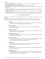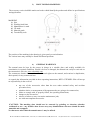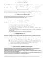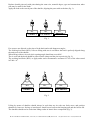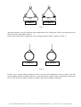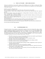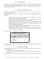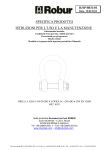
1
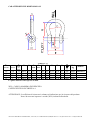
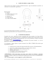
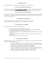
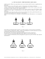
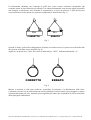
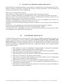
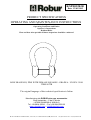
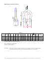
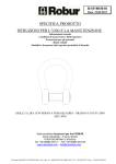
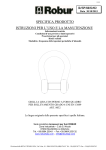
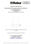
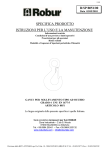
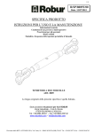
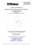
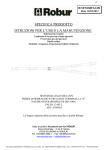
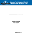
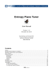
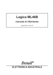
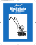
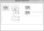
R/SP/8032R/00
Data 12/01/2015
SPECIFICA PRODOTTO
ISTRUZIONI PER L’USO E LA MANUTENZIONE
Informazioni tecniche
Condizioni d’uso previste e limiti operativi
Prescrizioni per gli operatori
Rischi residui
Modalità e frequenza delle ispezioni periodiche d’idoneità
GRILLI A LIRA CON PERNO A FORO QUADRO - GRADO 6 UNI EN 13889
ART. 8032R
La lingua originale della presente specifica è quella Italiana.
Sede produttiva Accessori per funi ROBUR
Zona Industriale – C.da S. Nicola
67039 SULMONA (L’AQUILA)
Tel. +39.0864.2504.1 – Fax +39.0864.253132
www.roburitaly.com – [email protected]
Divisione della BETA UTENSILI SPA, Via Volta, 18 - 20845 SOVICO (MB) ITALY Tel. +39.(0)39.20771-Fax + 39.(0)39.2010742
1) CARATTERISTICHE TECNICHE
Materiale:
STAFFA acciaio da bonifica
PERNO acciaio da bonifica
Trattamento Termico:
Bonifica
Norme di Riferimento:
Grillo
Materiale
Trattamento Superficiale:
STAFFA zincata a caldo per immersione
PERNO zincato A2E EN ISO 4042 e verniciato arancione
(RAL 2011)
UNI EN 13889
UNI EN 10084
Il collaudo viene eseguito in base a specifiche e regole interne in riferimento alla norma UNI EN ISO
9001.
L’articolo è conforme alla Direttiva Macchine 2006/42/CE.
Divisione della BETA UTENSILI SPA, Via Volta, 18 - 20845 SOVICO (MB) ITALY Tel. +39.(0)39.20771-Fax + 39.(0)39.2010742
CARATTERISTICHE DIMENSIONALI:
TABELLA “A”
MISURA
FILETT.
N°
Filetti
per
pollice
16
19
22
25
5/8
3/4
7/8
1”
11
10
9
8
ØA
B
48.0
60.0
71.0
84.0
C
33
43
51
58
D
D
mm
Poll.
12.7
16.0
19.0
22.0
1/2
5/8
3/4
7/8
D1
E
F
H
K
g
30
40
48
54
51
63
74
86
47.0
59.0
70.0
81.0
21.0
27.0
32.0
37.0
11 310
11 560
11 980
13 1460
WLL CODICE
kg
2000
3250
4750
6500
080320012
080320016
080320020
080320022
Le quote indicate sono espresse in mm.
WLL= CARICO MASSIMO DI ESERCIZIO
COEFFICIENTE DI SICUREZZA: 6
ATTENZIONE: il coefficiente di sicurezza è soltanto un’indicazione per la sicurezza del prodotto.
Non si devono mai superare i carichi (WLL) indicati nella tabella.
Divisione della BETA UTENSILI SPA, Via Volta, 18 - 20845 SOVICO (MB) ITALY Tel. +39.(0)39.20771-Fax + 39.(0)39.2010742
Definizioni:
• Carico massimo di esercizio (WLL): è il carico massimo che l’articolo può sopportare (lungo l’asse
principale, se non diversamente indicato) in condizioni di utilizzo.
• Coefficiente di sicurezza: è il rapporto tra il carico di rottura minimo garantito e il carico limite di
lavoro.
• Ispezione: controllo visivo relativo allo stato del grillo per individuare evidenti danneggiamenti o
usure che possono alterarne l’utilizzo.
• Esame accurato: esame visivo effettuato da una persona competente e, se necessario, coadiuvato da
altri mezzi, quali i controlli non-distruttivi, al fine di individuare danneggiamenti o usure che possono
alterare l’utilizzo del componente.
• Persona competente: persona designata, istruita correttamente, qualificata per conoscenza ed
esperienza pratica, che ha ricevuto le istruzioni necessarie per eseguire le prove e gli esami richiesti.
2)
SPECIFICHE DI COLLAUDO
L’accessorio è sottoposto a una serie di controlli a campione per accertarne la funzionalità prestazionale
e la rispondenza alla norma UNI EN 13889.
La numerosità del campione e i relativi piani di campionamento sono scelti in funzione della
caratteristica da verificare in accordo e per quanto previsto dalla norma UNI ISO 2859/1, e i risultati
archiviati nell’ufficio qualità dello stabilimento di Sulmona.
2.A Controllo visivo
Verifica la presenza di eventuali imperfezioni dovute a stampaggio, lavorazione
meccanica, rivestimento superficiale e rispondenza della marcatura a disegni di fase
interni.
2.B Controllo dimensionale
Verifica che le dimensioni dell’articolo rientrino nelle tolleranze stabilite dai relativi
disegni di costruzione interni.
2.C Analisi chimica
Verifica la rispondenza della composizione chimica del materiale.
2.D Analisi metallografica
Verifica il processo di bonifica: a 500 ingrandimenti si deve riscontrare una
distribuzione omogenea di martensite rinvenuta.
2.E Prove di trazione
Verifica che l’accessorio sottoposto a una trazione arrivi a rottura dopo che la forza
applicata abbia almeno superato il “WFL” moltiplicato per il coefficiente di sicurezza.
La prova è eseguita in accordo con la norma UNI 10002/1.
2.F Prova di fatica
Verifica che l’articolo sottoposto a trazione per 20.000 cicli con un carico di 1,5 volte il
“WFL” indicato nella tabella A non subisca rotture.
2.G Prova di durezza
Verifica che la durezza dell’articolo rientri nei valori stabiliti dai relativi disegni di
costruzione interni.
2.H Prova di resilienza
Verifica la tenacità del materiale: i provini di materiale, portati alla temperatura di -20°C
e sottoposti al test d’urto di Charpy, dovranno fornire un valore medio dell’energia
assorbita dopo l’impatto di almeno 27J. La prova è eseguita in accordo alle norme UNI
EN 13889, EN 10045-1, EN 10045-2.
Divisione della BETA UTENSILI SPA, Via Volta, 18 - 20845 SOVICO (MB) ITALY Tel. +39.(0)39.20771-Fax + 39.(0)39.2010742
3)
COME LEGGERE LA MARCATURA
Sull’accessorio sono stampate in maniera indelebile marcature e sigle che identificano il prodotto e ne
definiscono le caratteristiche e applicazioni.
MARCATURA
1) Misura
2) Carico massimo di esercizio
3) Marchio produttore
4) Marchio CE
5) Grado materiale
6) Codice di rintracciabilità
La posizione della marcatura sul disegno è solo indicativa.
Realmente le posizioni delle varie voci possono trovarsi in punti differenti.
4)
AVVERTENZE GENERALI
Il manuale deve essere custodito da persona responsabile allo scopo preposta, in un luogo idoneo,
affinché esso risulti sempre disponibile per la consultazione nel miglior stato di conservazione. In caso
di smarrimento o deterioramento, la documentazione dovrà essere prontamente sostituita scaricandola
dal sito del costruttore: www.roburitaly.com.
Il costruttore si riserva la proprietà materiale ed intellettuale del presente manuale e ne vieta la
duplicazione, anche parziale, per fini commerciali.
Con riferimento a quanto riportato in queste istruzioni d’uso, BETA UTENSILI SPA declina ogni
responsabilità in caso di:
•
•
•
•
•
•
uso degli accessori contrario alle leggi nazionali sulla sicurezza e sull’antinfortunistica;
errata scelta o predisposizione del mezzo con il quale saranno connessi;
mancata o errata osservanza delle istruzioni per l’uso;
modifiche agli accessori;
uso improprio e omessa manutenzione ordinaria;
uso combinato ad accessori non conformi.
!ATTENZIONE: I dati di marcatura non devono essere rimossi con molature o abrasioni,
(neanche accidentali; i grilli senza riferimenti di identificazione devono essere resi inutilizzabili e
rottamati).
Non è consentito apporre caratteri aggiuntivi a quelli di fabbricazione.
Divisione della BETA UTENSILI SPA, Via Volta, 18 - 20845 SOVICO (MB) ITALY Tel. +39.(0)39.20771-Fax + 39.(0)39.2010742
5)
CRITERI DI SCELTA
I parametri che devono essere attentamente considerati nella scelta dei grilli sono:
5.A CARICO MASSIMO DI ESERCIZIO
Il peso del carico da sollevare deve essere inferiore o uguale al valore del carico massimo di esercizio
(WLL) previsto per il grillo preso in considerazione, stampato sul prodotto e riportato nella tabella “A”.
5.B ELEMENTO DI ACCOPPIAMENTO
Assicurarsi che l’elemento di accoppiamento sia adeguato alle caratteristiche di portata del grillo, abbia
uno spessore e una composizione chimica adeguati e garantisca una resistenza meccanica sufficiente alla
trazione esercitata dalla presa.
5.C TEMPERATURE D’IMPIEGO
La temperatura d’impiego consentita dovrà essere compresa tra –20 °C e +200 °C.
Al di fuori di questi valori non è più garantito il carico massimo di utilizzazione.
6) CONDIZIONI NON AMMESSE
Non è consentita la movimentazione dei seguenti carichi:
•
•
•
•
•
•
aventi un peso superiore al carico massimo di esercizio;
aventi una struttura non sufficientemente resistente alla trazione esercitata dalla presa;
aventi temperature superiori o inferiori a quelle ammesse;
classificati come pericolosi (p. es. metalli fusi, materiali infiammabili, corrosivi, fissili,
esplosivi ecc.);
che possono cambiare la loro configurazione statica e/o il loro baricentro o il loro stato
chimicofisico;
immersi in soluzioni acide o esposti a vapori acidi.
7)
CONTROLLI PRELIMINARI
Prima della messa in servizio e/o del montaggio gli accessori devono essere controllati da una persona
competente adeguatamente addestrata.
• Controllare l’integrità dell’accessorio e in particolare che non vi siano tagli, piegature,
incisioni, abrasioni, incrinature o cricche, filetti irregolari, corrosioni, bave taglienti,
usure provocate dall’utilizzo o difetti dovuti a cattivo stoccaggio.
• Rilevare e registrare le dimensioni con riferimento alla tabella “A”.
• Controllare l’integrità della marcatura in tutte le sue parti, sia della staffa che del
perno, in particolare le prescrizioni di portata e grado del materiale, al fine di
identificare con precisione l’accessorio in funzione del carico di lavoro.
• Verificare la bontà dell’accoppiamento tra staffa e perno e tra i filetti.
Divisione della BETA UTENSILI SPA, Via Volta, 18 - 20845 SOVICO (MB) ITALY Tel. +39.(0)39.20771-Fax + 39.(0)39.2010742
8) INSTALLAZIONE - ISTRUZIONI PER IL MONTAGGIO
I grilli con perno filettato sono generalmente usati come elementi mobili di unione in applicazioni non
permanenti.
Svitare ed estrarre il perno dalla staffa; eseguire il collegamento con l’elemento da sollevare.
Avvitare a fondo il perno, verificando che sia completamente serrato contro la staffa, senza creare
sovratensioni sui filetti o flessioni verso l’interno del grillo.
Un appoggio scorretto del perno sulla staffa può essere dovuto al perno curvato, alla filettatura troppo
serrata o rovinata, oppure al disallineamento dei fori della staffa. Non utilizzare il grillo in queste
condizioni.
Non sostituire mai il perno dei grilli, eccetto che con uno della stessa misura, grado del materiale, tipo e
costruzione, perché può non essere idoneo per i carichi imposti.
Applicare il carico sulla parte curva del grillo, realizzando un perfetto allineamento tra i vari componenti
(fig.1).
WLL
WLL
WLL
CORRETTO
ERRATO
ERRATO
Fig. 1
Sono ammessi dei distanziali liberi sul perno, per centrare il gancio ed evitare pericolose inclinazioni.
Il carico massimo di utilizzazione (WLL) è riferito al sollevamento con un solo tirante dove il carico è
perfettamente allineato lungo l’asse principale del grillo.
Nel sollevamento con due tiranti l’angolo di apertura degli stessi non deve superare 90°.
I tiranti devono essere posizionati sulla staffa, mentre il gancio va posto sul perno (fig. 2).
Il carico massimo di utilizzazione (WLL) da applicare in questi casi è pari al 70% del valore indicato
nella tabella”A”.
MAX 90°
WLL
WLL
WLL
CORRETTO
ERRATO
ERRATO
Fig. 2
Divisione della BETA UTENSILI SPA, Via Volta, 18 - 20845 SOVICO (MB) ITALY Tel. +39.(0)39.20771-Fax + 39.(0)39.2010742
Il sollevamento effettuato con l’impiego di grilli deve essere sempre realizzato consentendo agli
eventuali tiranti la piena libertà di movimento e di autoposizionamento; non devono quindi presentarsi
mai forzature o interferenze tra l’elemento di sospensione e il carico da sollevare. I grilli non devono
essere utilizzati in sollevamenti che generano componenti di forza laterali (fig. 3).
WLL
WLL
CORRETTO
ERRATO
Fig. 3
Quando si usano i grilli nella configurazione di brache con nodo scorsoio, la parte scorrevole della fune
deve passare sulla parte curva del grillo (fig. 4).
Applicare, in questo caso, l’80% del carico di utilizzazione, “WLL”, indicato nella tabella “A”.
CORRETTO
ERRATO
Fig. 4
Mettere in tensione le funi senza sollevare; controllare il baricentro e la distribuzione delle forze.
Considerare che nel caso di sollevamento di carichi squilibrati con due tiranti, il peso maggiore è sempre
sostenuto dal tirante più corto. Adottare gli accorgimenti più idonei per riequilibrare il carico in funzione
della tipologia di imbracatura.
Divisione della BETA UTENSILI SPA, Via Volta, 18 - 20845 SOVICO (MB) ITALY Tel. +39.(0)39.20771-Fax + 39.(0)39.2010742
9)
USO DELL’ACCESSORIO - PRESA E MANOVRA
Prestare sempre la massima attenzione a ogni specifico avvertimento per la movimentazione del carico.
Prima di azionare il sollevatore, assicurarsi che il carico sia libero di muoversi e non sia bloccato da
elementi di collegamento o da altri impedimenti.
Mettere in tiro le funi prima di sollevare.
Stare lontani con le mani o altre parti del corpo quando le funi sono poste in tensione.
Il carico va sollevato lentamente, va controllato che sia sicuro e che assuma la posizione preventivata.
Muovere il carico con movimenti lenti, lineari e costanti, evitando brusche accelerate o frenate che, per
effetto dell’inerzia, possono creare pericolose oscillazioni.
Predisporre anticipatamente il luogo di deposito al suolo del carico, assicurandosi che il terreno (o il
pavimento) sia adeguatamente resistente per sopportare il carico.
Assicurarsi che l’accesso al luogo di deposito sia privo di ostacoli e che le persone siano a distanza di
sicurezza.
Il carico deve essere appoggiato con cautela, facendo attenzione che la braca non si impigli.
Prima di allentare le funi, controllare che il carico sia ben supportato e stabile.
Una volta che il carico è appoggiato in sicurezza, il sistema di imbracatura deve essere rimosso a mano,
e mai allontanato con l’apparecchio di sollevamento.
10)
CONTROINDICAZIONI D’USO
L’utilizzo dell’accessorio per scopi non previsti, il suo uso in condizioni estremamente pericolose e la
carenza di manutenzione possono comportare gravi situazioni di pericolo per l’incolumità delle
persone esposte e di danno per l’ambiente di lavoro, oltre che pregiudicare la funzionalità e la sicurezza
effettiva del prodotto. Le azioni di seguito citate, che, ovviamente, non possono coprire l’intero arco di
potenziali possibilità di “cattivo uso” dell’accessorio, costituiscono tuttavia quelle “ragionevolmente”
più prevedibili. Quindi:
•
•
•
•
•
•
•
•
•
NON utilizzare l’accessorio collegandolo ad apparecchiature di dimensioni, temperatura,
punto d’aggancio e forma non idonei alle sue caratteristiche;
NON sollevare il carico sottoponendo l’accessorio a sollecitazioni di tipo pulsante;
NON fare oscillare il carico durante la movimentazione;
NON utilizzare l’accessorio per sollevare e trasportare carichi sospesi in volo (aeromobili);
NON usare l’accessorio per trazionare carichi vincolati;
NON mettere in tensione apparecchiature che possono cambiare la loro configurazione
statica, il loro baricentro o lo stato chimicofisico;
NON utilizzare l’accessorio per il sollevamento o il trasporto di persone o animali;
NON operare in aree dove è prescritto l’uso di componenti antideflagranti/antiscintilla o in
presenza di forti campi magnetici;
NON saldare sull’accessorio particolari metallici, né intervenire con riporti di saldatura o
utilizzarlo come massa per saldatrici.
Divisione della BETA UTENSILI SPA, Via Volta, 18 - 20845 SOVICO (MB) ITALY Tel. +39.(0)39.20771-Fax + 39.(0)39.2010742
11)
IDONEITÀ ALL’UTILIZZO
L’accessorio è stato sottoposto a collaudo a campione presso il costruttore per accertare la rispondenza
funzionale e prestazionale dello stesso. L’attestato che accompagna la fornitura certifica il superamento
con esito positivo dei test di collaudo. L’utilizzatore deve eseguire in ogni caso, prima di iniziare a
operare, la verifica della rispondenza funzionale e prestazionale dell’accessorio installato per confermare
l’idoneità all’impiego dell’intera installazione.
12)
ISPEZIONE E MANUTENZIONE
Comprende una serie di operazioni eseguite da personale competente istruito allo scopo, relative a
controlli ed esami accurati durante l’impiego.
Di seguito l’elenco dei controlli da effettuare con cadenze indicate nella tabella “Interventi di
manutenzione e controllo”.
•
•
•
•
•
VISIVO: verificare l’assenza di difetti superficiali, quali cricche, incisioni, tagli o fessure,
abrasioni.
CONDIZIONI DEL FILETTO: esaminare lo stato del filetto, che non deve presentare
usure, deformazioni e ammaccature, e l’accoppiamento deve essere preciso, stabile e senza
eccessivo gioco.
DEFORMAZIONE: verificare che l’accessorio non sia deformato, misurando con un
calibro le dimensioni critiche, come indicato nella tabella “A”. NON sono tollerate
deformazioni rispetto alle quote rilevate alla prima messa in servizio.
USURA: verificare che i punti di contatto non siano usurati, misurando con un calibro le
dimensioni critiche indicate nella tabella “A”.
STATO DI CONSERVAZIONE: verificare l’assenza di ossidazione e corrosione,
soprattutto in caso di utilizzo all’aperto; verificare l’assenza di cricche con metodi idonei
(p. es. liquidi penetranti).
Le registrazioni di questi controlli devono essere conservate.
Tabella interventi di manutenzione e controllo
Tipo di controllo
Controllo visivo gener.
Condizioni del filetto
Deformazione
Usura
Stato di conservazione
A ogni utilizzo
Mese
Anno
x
x
x
x
x
Nel caso in cui il grillo sia sottoposto a un utilizzo gravoso, è necessario effettuare le verifiche di usura e
stato di conservazione con maggiore frequenza.
13)
DEMOLIZIONE E ROTTAMAZIONE DELL’ACCESSORIO
L’accessorio deve essere demolito mediante taglio, in modo tale che non possa più essere utilizzato, sia
al termine della vita prevista, che nel caso presenti:
- una deformazione permanente rispetto alla misura originale;
- eventuali cricche, distorsioni e/o se si riscontrano riduzioni di sezione rispetto alla misura
originale;
- se le condizioni del filetto non garantiscono il perfetto accoppiamento tra le parti, filetti usurati,
deformati, irregolari ecc.
Divisione della BETA UTENSILI SPA, Via Volta, 18 - 20845 SOVICO (MB) ITALY Tel. +39.(0)39.20771-Fax + 39.(0)39.2010742
R/SP/8032R/00
Date 12/01/2015
PRODUCT SPECIFICATIONS
OPERATING AND MAINTENANCE INSTRUCTIONS
Technical Specifications
Operating Conditions and Limits
Operator’s Instructions
Residual Risks
How and how often periodical fitness inspections should be conducted
BOW SHACKLES, PINS WITH FEMALE SQUARES - GRADE 6 - UNI EN 13889
ITEM 8032R
The original language of this technical specification is Italian
Manufacturing site ROBUR wire rope accessories
Zona Industriale – C.da S. Nicola
I-67039 SULMONA (L’AQUILA)
Tel. +39.0864.2504.1 – Fax +39.0864.253132
www.roburitaly.com – [email protected]
Division of BETA UTENSILI SPA, Via Volta, 18 - 20845 SOVICO (MB) ITALY Tel. +39.(0)39.20771-Fax + 39.(0)39.2010742
1) TECHNICAL SPECIFICATIONS
Material:
CLAMP hardening and tempering steel
PIN hardening and tempering steel
Heat Treatment:
Hardened and tempered
Reference Standards:
Shackle
Material
Surface Treatment:
CLAMP
hot-dip galvanized
PIN
galvanized A2E EN ISO 4042 and orange
painted (RAL 2011)
UNI EN 13889
UNI EN 10084
The test is performed on the basis of in-house specifications and rules in accordance with UNI EN ISO
9001.
The item complies with Machine Directive 2006/42/EC.
Division of BETA UTENSILI SPA, Via Volta, 18 - 20845 SOVICO (MB) ITALY Tel. +39.(0)39.20771-Fax + 39.(0)39.2010742
DIMENSIONAL SPECIFICATIONS:
TABLE “A”
ØA
SIZE
16
19
22
25
Number
of
THREAD
threads
per Inc.
5/8
3/4
7/8
1”
11
10
9
8
B
48.0
60.0
71.0
84.0
C
33
43
51
58
D
D
mm
INCH.
12.7
16.0
19.0
22.0
1/2
5/8
3/4
7/8
D1
E
F
H
K
g
30
40
48
54
51
63
74
86
47.0
59.0
70.0
81.0
21.0
27.0
32.0
37.0
11 310
11 560
11 980
13 1460
WLL
kg
2000
3250
4750
6500
CODE
080320012
080320016
080320020
080320022
All measurements are expressed in mm.
WLL= WORKING LOAD LIMIT
SAFETY COEFFICIENT: 6
CAUTION:
The safety coefficient is only provided by way of example, in relation to product safety.
The working load limits (WLL) shown in the table should never be exceeded.
Division of BETA UTENSILI SPA, Via Volta, 18 - 20845 SOVICO (MB) ITALY Tel. +39.(0)39.20771-Fax + 39.(0)39.2010742
Definitions:
• Working load limit (WLL): the maximum load the item can support (along the main axis, if not
otherwise specified) under operating conditions.
• Safety coefficient: guaranteed minimum breaking load to working load limit ratio.
• Inspection: visual testing of the state of the shackle, to check for clear damage or wear which may
affect its use.
• Accurate examination: visual inspection performed by a trained person, supported, if need be, by
any other instruments, including non-destructive testing, to check for damage or wear which may
affect the use of the part.
• Trained person: a designated, suitably trained person who has proper know-how and practical
expertise and has been given the instructions needed to perform any required tests and examinations.
2)
TESTING SPECIFICATIONS
The accessory is subjected to several stringent spot checks for serviceability and compliance with UNI
EN 13889.
The number of samples and the related sampling plans are chosen according to the characteristic to test
under UNI ISO 2859/1, and the results are filed in the quality department of the factory in Sulmona.
2.A Visual test
Testing for defects resulting from forming, mechanical working, surface coating and
correspondence between the marking and in-house drawings.
2.B Dimensional test
Making sure that the dimensions of the item meet such tolerances as established in inhouse working drawings.
2.C Chemical analysis
Making sure that the chemical composition of the material complies with the limits
established under the relevant standards.
2.D Metallographic analysis
Testing the hardening and tempering process: at 500 enlargements, tempered martensite
should be uniformly distributed.
2.E Tensile stress tests
Making sure that the accessory subjected to tensile stress will break, after the applied
force has at least exceeded the “WFL” as multiplied by the safety coefficient.
The test is performed in accordance with UNI 10002/1.
2.F Fatigue test
Making sure that the item subjected to tensile stress for 20,000 cycles with a load 1.5
times as high as the “WFL” stated in Table A will not break.
2.G Hardness test
Making sure that the hardness of the item lies within the limits established in the relevant
in-house working drawings.
2.H Charpy impact test
Testing the toughness of the item: the samples have to be tested at a temperature of -20°C
and must have a minimum average impact value of 27J. The test is performed according
to UNI EN 13889, EN 10045-1 and EN 10045-2.
Division of BETA UTENSILI SPA, Via Volta, 18 - 20845 SOVICO (MB) ITALY Tel. +39.(0)39.20771-Fax + 39.(0)39.2010742
3)
HOW TO READ MARKINGS
The accessory carries indelible marks and codes which identify the product and define its specifications
and applications.
MARKING
1) Size
2) Working load limit
3) Manufacturer’s mark
4) CE mark
5) Material grade
6) Traceability code
The position of the marking in the drawing is given purely as an indication.
The various items may actually be found in different positions.
4)
GENERAL WARNINGS
The manual must be kept by the person in charge in a suitable place and readily available for
consultation, in optimal conditions. should it be lost or damaged, the manual can easily be retrieved on
the constructor's web site: www.roburitaly.com
The constructor detains all material and intellectual rights on the manual, and restricts its duplication,
albeit partial, for any commercial use.
As regards the information provided in these operating instructions, BETA UTENSILI SPA will accept
no responsibility in the event of:
•
•
•
•
•
•
any use of the accessories other than the uses under national safety and accident
prevention laws;
mistaken choice or arrangement of the apparatus they are going to be connected to;
failure to comply with, or properly follow, the operating instructions;
changes to the accessories;
misuse or failure to carry out routine maintenance jobs;
use with noncompliant accessories.
!CAUTION: The marking data should not be removed by grinding or abrasion (whether
accidental or not – any shackles that do not carry any identification references should be made
unusable and scrapped).
No characters other than the manufacturer’s may be affixed.
Division of BETA UTENSILI SPA, Via Volta, 18 - 20845 SOVICO (MB) ITALY Tel. +39.(0)39.20771-Fax + 39.(0)39.2010742
5)
SELECTION CRITERIA
The following parameters should be carefully considered in choosing the shackles:
5.A WORKING LOAD LIMIT
The weight of the load to lift should be lower than or equal to the working load limit (WLL)
recommended for the shackle being considered, as printed on the product and shown in Table “A”.
5.B CONNECTING PART
Make sure that the connecting part suits the load capacity of the shackle, is thick enough, has a proper
chemical composition and an adequate mechanical resistance to traction forces.
5.C OPERATING TEMPERATURES
The permissible operating temperature should range between –20 °C and +200 °C.
The working load limit will not be guaranteed outside this range.
6) NONPERMISSIBLE CONDITIONS
The following loads should not be handled:
•
•
•
•
•
•
any load exceeding the working load limit in weight;
any load whose frame is not resistant enough to traction forces;
any load whose temperature does not lie within the permissible range;
any load classified as hazardous (e.g. melted metal, flammable, corrosive, fissile,
explosive materials etc.);
any load that may change its static configuration and/or centre of gravity or chemical and
physical state;
any load immersed in acid solutions or exposed to acid vapours.
7)
PRELIMINARY TESTS
Before the accessories are operated and/or assembled, they should be tested by a suitably trained person.
• Check the state of the accessory; in particular make sure that it is free from cuts,
bends, indentations, abrasions, cracks, irregular threads, corrosions, sharp burrs, wear
or defects resulting from improper storage.
• Measure and record the dimensions according to Table “A”.
• Check the state of all the parts of the markings, in both the clamp and the pin; in
particular make sure that the capacity and material degree requirements are met, so
that the accessory can be accurately identified according to the working load.
• Make sure that the clamp and pin and the threads fit.
8) INSTALLATION - ASSEMBLY INSTRUCTIONS
Shackles with threaded pins are normally used as moving connecting parts in temporary applications.
Unscrew the pin and remove it from the clamp; connect the shackle to the part to lift.
Tighten the pin, making sure that it is locked to the clamp, avoiding overpulling the threads or causing
flexure towards the inner part of the shackle.
A pin incorrectly supported by the clamp may be the result of a bent pin, overtight or damaged thread or
misaligned clamp holes. Do not use the shackle under such conditions.
Division of BETA UTENSILI SPA, Via Volta, 18 - 20845 SOVICO (MB) ITALY Tel. +39.(0)39.20771-Fax + 39.(0)39.2010742
Replace shackle pins only with pins sharing the same size, material degree, type and construction; other
pins may be unfit for the loads.
Apply the load to the curved part of the shackle, aligning the parts with each other (fig. 1).
WLL
WLL
CORRETTO
CORRECT
ERRATO
INCORRECT
WLL
ERRATO
INCORRECT
Fig. 1
Free spacers are allowed on the pin to fit the hook and avoid dangerous angles.
The working load limit (WLL) refers to lifting with one tie rod where the load is perfectly aligned along
the main axis of the shackle.
When lifting with two tie rods, their opening angle should not exceed 90°.
The tie rods and the hook should be placed on the clamp and the pin respectively (fig. 2).
The working load limit (WLL) to apply under such circumstances accounts for 70% of the value stated
in Table “A”.
MAX 90°
WLL
CORRETTO
CORRECT
WLL
ERRATO
INCORRECT
WLL
ERRATO
INCORRECT
Fig. 2
Lifting by means of shackles should always be such that any tie rods can freely move and position
themselves; hence no forcing or interference should occur between the hanging part and the load to lift.
The shackles should not be used when lifting results in lateral force components (fig. 3).
Division of BETA UTENSILI SPA, Via Volta, 18 - 20845 SOVICO (MB) ITALY Tel. +39.(0)39.20771-Fax + 39.(0)39.2010742
WLL
WLL
CORRETTO
CORRECT
ERRATO
INCORRECT
Fig. 3
When any shackle is used in slipknot sling configurations, the sliding part of the rope should pass onto
the curved part of the shackle (fig. 4).
Under such circumstances, apply 80% of the working load limit (WLL) stated in “Table A”.
CORRECT
CORRETTO
INCORRECT
ERRATO
Fig. 4
Pull the ropes without lifting; check the centre of gravity and distribution of forces. Please note that
when unbalanced loads are lifted with two tie rods, the heavier weight is always supported by the shorter
tie rod. Take the most suitable measures to balance the load according to sling type.
Division of BETA UTENSILI SPA, Via Volta, 18 - 20845 SOVICO (MB) ITALY Tel. +39.(0)39.20771-Fax + 39.(0)39.2010742
9)
USING ACCESSORY – GRIP AND HANDLING
Always pay attention to any specific warning when handling the load. Before operating the lifting
apparatus, make sure that the load is capable of freely moving and is not stopped by any connecting parts
or any other obstacles.
Pull the ropes before lifting the load.
Keep your hands or any other parts of your body away if the ropes have been pulled.
The load should be lifted slowly, making sure that it has been fixed firmly and takes the expected
position.
Move the load slowly, linearly and continuously, avoiding sudden acceleration or braking, which may
cause – through inertia – dangerous swinging.
Choose the place where to put down the load onto the ground beforehand, making sure that the ground
(or the floor) is capable of supporting the load.
Make sure that the place where the load is to be put down is free from obstacles and that everybody is
safely distant from it.
The load should be put down cautiously, being careful not to get the chain sling entangled.
Before loosening the ropes, make sure that the load is suitably supported and firm.
Once the load has been put down safely, the sling system should be removed by hand and should never
be moved away with the lifting apparatus.
10)
NONPERMISSIBLE USE
Using the accessory for any purposes other than the purposes it has been designed for, using it under
extremely dangerous conditions and performing poor maintenance may pose a severe hazard to the
safety of the people being exposed and cause severe damage to the working environment, while
affecting the actual serviceability and safety of the product. The precautions mentioned below, which,
obviously enough, cannot cover the whole spectrum of potential “misuses” of the accessory, should be
“reasonably” deemed to be the most common steps to take. Therefore:
•
•
•
•
•
•
•
•
•
DO NOT connect the accessory to any apparatus which does not match its specifications in
terms of size, temperature, hook-up point and shape;
DO NOT lift the load while subjecting the accessory to impulsive strain;
DO NOT let the load swing while handling it;
DO NOT use the accessory to lift and carry suspended loads in flight (aircrafts);
DO NOT use the accessory to pull restrained loads;
DO NOT stretch any apparatus that may change its static configuration, centre of gravity or
chemical and physical state;
DO NOT use the accessory to lift or carry people or animals;
DO NOT work in areas where any explosion/spark-proof parts are expected to be used or
in the presence of big magnetic fields;
DO NOT weld any metal parts to the accessory; do not use any filling welds; do not use
the accessory as mass for any welder.
Division of BETA UTENSILI SPA, Via Volta, 18 - 20845 SOVICO (MB) ITALY Tel. +39.(0)39.20771-Fax + 39.(0)39.2010742
11)
FITNESS FOR USE
The accessory was subjected to spot check in order to test serviceability and performance at the
manufacturer’s. The certificate supplied with it states that the tests were passed. However, before
starting working, the user should test the installed accessory for serviceability and performance, to prove
the entire system is fit for use.
12)
INSPECTION AND MAINTENANCE
Inspections and maintenance jobs should be carried out by trained personnel, who should perform
accurate tests during operation.
Below is a list of tests to perform at such intervals as stated in the table “Maintenance jobs and
inspections”.
•
•
•
•
•
VISUAL TEST: making sure that the accessory is free from surface defects, including
cracks, indentations, cuts, fissures and abrasions.
THREAD TEST: making sure that the thread is free from wear, deformation and dents,
that its fit is accurate and stable, and that there is not too much clearance.
DEFORMATION TEST: making sure that the accessory has not got deformed, using a
gauge to measure such critical dimensions as shown in Table “A”. NO
DEFORMATIONS will be tolerated compared to the measurements made when the
accessory was first put into operation.
WEAR TEST: making sure that the points of contact are not worn, using a gauge to
measure such critical dimensions as shown in Table “A”.
PRESERVATION TEST: making sure that the accessory is free from oxidation and
corrosion, especially in case of outdoor use; using suitable methods (e.g. liquid penetrants)
to make sure that it is free from cracks.
The results of the above-mentioned tests should be stored.
Maintenance jobs and inspections
Type of inspection
Whenever used
General visual inspection
Thread state
Deformation
Wear
State of preservation
Month
Year
x
x
x
x
x
If the shackle has been used for heavy-duty jobs, both wear and the state of preservation should be tested
for more frequently.
13)
SCRAPPING ACCESSORY
The accessory should be scrapped by cutting, so that it can no longer be used, whether at the end of its
expected lifetime or if:
- it is permanently worn compared to the original size;
- any cracks or distortions are shown, and/or the sections have become small compared to the
original size;
the state of the thread is such that the parts do not fit perfectly, any threads are worn, deformed, irregular
etc.
Division of BETA UTENSILI SPA, Via Volta, 18 - 20845 SOVICO (MB) ITALY Tel. +39.(0)39.20771-Fax + 39.(0)39.2010742