1
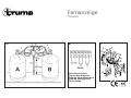
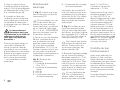
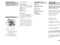
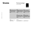
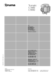
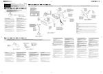
Fernanzeige
Triomatic
Triomatic
Gebrauchsanweisung
Einbauanweisung
Seite 3
50020-43700 · 01 · 02/2007 · 2’B · ©
Im Fahrzeug mitzuführen!
Operating instructions
Installation instructions
Bruksanvisning
Monteringsanvisning
Skall medföras i fordonet!
Page 5
To be kept in the vehicle!
Mode d’emploi
Instructions de montage
Page 7
À garder dans le véhicule !
Istruzioni per l’uso
Istruzioni di montaggio
Pagina 9
Da tenere nel veicolo!
Truma Gerätetechnik
GmbH & Co. KG
Postfach 1252
85637 Putzbrunn
Service
Telefon +49 (0)89 4617-2142
Telefax +49 (0)89 4617-2159
[email protected]
www.truma.com
Sida 11
Fernanzeige
Triomatic
A
B
C
6
17 Ø
m
55
m
14
10
12
Anschlussschema
Connecting diagram
Schéma de branchement
Schema collegamenti
Elanslutning
16
11
16
15
Fernanzeige
für das
Gasdruckregler-Set
Triomatic
Sommerbetrieb:
Schalter nach unten (a).
Die Leuchtdioden zeigen an,
welche der beiden Flaschen
das Gas liefert:
grüne Leuchtdiode =
Betriebsflasche (A),
rote Leuchtdiode =
Reserveflasche (B).
Winterbetrieb:
Um Störungen der Gasanlage
im Winterbetrieb zu verhindern, kann die Fernanzeige
durch ein oder zwei Eis-Ex
(Art.-Nr. 53100-01) ergänzt
werden.
Gebrauchsanweisung
Triomatic
c
d
e
Inbetriebnahme
b
a
a = Ein (Sommerbetrieb)
b = Aus
c = Ein und Heizen (Winterbetrieb bei montiertem
Eis-Ex – Sonderzubehör)
d = Grüne Kontrollleuchte
e = Rote Kontrollleuchte
Schalter nach oben (c). Zusätzlich zur Anzeige wird der
Betriebsregler (Bild A 1)
beheizt. Mit einem zweiten
Eis-Ex kann auch der Reserveregler (2) beheizt werden.
Technische Daten
Einbauanweisung
Spannung:
12 V
Stromaufnahme
Sommerbetrieb:
1,5 mA
Winterbetrieb mit Eis-Ex:
320/640 mA
Gasrohranschluss:
8 mm
Produkt-Ident-Nummer:
CE-0085AS0417
Einbau und Reparatur der
Fernanzeige darf nur vom
Fachmann durchgeführt
werden.
Bei Verwendung von fahrzeug- bzw. herstellerspezifischen Bedienteilen, muss
der elektrische Anschluss
gemäß der Truma Schnittstellenbeschreibung erfolgen.
Montage des
Druckschalters
1. Bild A: Gasschlauch (3)
am T-Stück (4) abschrauben.
2. Druckschalter (5) am
T-Stück (4) anschrauben.
3. Gasschlauch (3) am Druckschalter (5) anschrauben.
Der Druckschalter (5) muss
in einer hängend senkrechten Einbaulage auf einer
beliebigen Seite des T-Stücks
montiert werden.
3
4. Das 2-polige Anschlusskabel (6) mit Isolierband parallel
zum Anlagenregler (7) und
Gasrohr (8) verlegen.
5. Kabel nach innen zum
vorgesehenen Platz für das
Bedienteil verlegen. Falls erforderlich, mit einem Kabel
2 x 0,75 mm² verlängern.
Der elektrische Anschluss bzw. die
Verbindung zu einer Kabelverlängerung darf nicht im
Flaschenkasten erfolgen!
Für Flaschenkasten-Durchführung (9) Gummitülle
oder Karosseriedichtmittel
verwenden. Durchführung
mindestens 50 cm über dem
Boden des Flaschenkastens
– oder in einem Schutzrohr
verlegt – vorsehen.
Elektrischer Anschluss
1. Bild C: Platz für das Bedienteil (10) an gut sichtbarer
Stelle vorsehen.
Ist eine Unterputzmontage des Bedienteils
nicht möglich, liefert Truma
auf Wunsch einen Aufputzrahmen (11 – Art.-Nr. 4000052600) als Sonderzubehör.
2. Loch Ø 55 mm bohren.
Anschlusskabel des Druckschalters (6) und 12 V Zuleitung (17) von hinten durch
die Bohrung in der Wand
führen und gemäß Anschlussschema am Bedienteil
anklemmen.
Bild B: Anschlussschema
1 = Zuleitung Plus 12 V
2 = Zuleitung Minus
3 = Eis-Ex
4 = Eis-Ex
5 = Minusleitung (schwarz)
vom Druckschalter
6 = Plusleitung (rot)
vom Druckschalter
Die Klemmen 3 und 4 sind
für den Anschluss von einem
oder zwei Eis-Ex vorgesehen.
Diese Anschlusskabel können
beliebig angeklemmt werden.
4
3. Bild C: Hintere Abdeckkappe (14) als Zugentlastung
aufsetzen und Bedienteil (10)
mit 4 Schrauben (12) befestigen. Anschließend Abdeckrahmen (15) aufstecken.
den Trafo-Stecker kann nur
ein Eis-Ex betrieben werden
(ein Anschluss von weiteren
12 V-Geräten ist nicht
möglich).
Als Abschluss zum
Abdeckrahmen liefert
Truma als Sonderzubehör
Seitenteile (16).
Funktionsprüfung
4. Gerät am abgesicherten
Bordnetz (Zentralelektrik 5 –
10 A) mit Kabel 2 x 0,75 mm²
anschließen. Minusleitung an
Zentralmasse. Bei direktem
Anschluss an die Batterie ist
die Plus- und Minusleitung
abzusichern.
Bei Verwendung von
Netzteilen ist zu beachten,
dass die Ausgangsspannung
zwischen 11 V und 15 V liegt
und die Wechselspannungswelligkeit < 1,2 Vss beträgt.
Die Fernanzeige kann über
den Truma Trafostecker
(Art.-Nr. 53110-01) auch mit
230 V betrieben werden.
Der Trafostecker liefert 12 V
Wechselstrom mit geringer
Leistung. Die zwei Kabel am
Trafostecker können beliebig
angeklemmt werden. Über
Nach dem Einbau muss die
Dichtigkeit der Gaszuleitung
nach der Druckabfallmethode
geprüft werden. Anschließend
gemäß der Gebrauchsanweisung sämtliche Funktionen
prüfen.
Die Gebrauchsanweisung ist
dem Betreiber auszuhändigen.
Remote indicator
for the Triomatic
Gas Pressure
Regulator Set
Summer operation:
Move the switch down to (a).
The LED's indicate which of
the two cylinders is supplying
the gas:
green LED =
operating cylinder (A),
red LED =
reserve cylinder (B).
Winter operation:
To prevent malfunctions of
the gas system during winter
operation, the remote indicator can be supplemented
with one or two defroster
(Eis-Ex – part no. 53100-01).
Operating
instructions
Triomatic
c
d
e
Switching on
b
a
Move the switch up to (c).
The operating regulator
(fig. A 1) is now heated in
addition to indicating the cylinder in operation. A second
defroster (Eis-Ex) can also
heat the reserve regulator (2).
Technical data
Voltage:
12 V
Current input
summer operation:
1,5 mA
winter operation with
defroster (Eis-Ex):
320/640 mA
Gas pipe connection:
8 mm
Product Ident.Number:
CE-0085AS0417
Installation
instructions
Installation and repair work
to the remote indicator is
only to be carried out by
an expert.
When using specific vehicle
or manufacturer control
panels, the electrical connection must be in accordance
with the Truma interface
description.
Assembly of
pressure switch
1. Fig. A: Unscrew gas hose
(3) at T-piece (4).
2. Screw pressure switch (5)
to T-piece (4).
3. Screw gas hose (3) to pressure switch (5).
a = On (summer operation)
b = Off
c = On and Heat (winter
operation with Eis-Ex ice
preventer fitted – special
accessory)
d = green indictor lamp
e = red indicator lamp
The pressure switch (5) must
be fitted in a suspended
vertical installation location on whichever side of the
T-piece is most convenient.
5
4. Route the 2-pole connecting cable (6) with insulating
tape parallel to the system
regulator (7) and gas pipe (8).
5. Route cable to the inside, to the place where the
control panel is to be installed. Lengthen using a 2 x
0.75 mm² cable, if necessary.
The electrical connection or the connection to a cable extension must not be effected
in the cylinder container.
For passing cables through
a cylinder container (9), use
rubber grommets or bodywork sealing material. Establish the cable run at least
50 cm above the base of the
cylinder container, or lay it
inside a protective tube.
Electrical connection
1. Fig. C: Choose a place for
the control panel (10) in a position which is easy to view.
If it is not possible to
install the control panel
flush with the surface, Truma
can provide a surface-mounting frame (11) on request, as
a special accessory (part no.
40000-52600).
2. Drill two holes of 55 mm
diameter. Guide the connection cable for the pressure
switch (6) and the 12 V feed
cable (17) from the rear
through the drillhole in the
wall and connect it to the
control panel in accordance
with the connecting diagram.
Fig. B: Connecting diagram
1 = Feed cable, 12 V positive
2 = Feed cable, negative
3 = Eis-Ex ice preventer
4 = Eis-Ex ice preventer
5 = Negative lead (black)
from pressure switch
6 = Positive lead (red) from
pressure switch
The terminals 3 and 4 are
intended for the connection
of one or two Eis-Ex ice preventers. These connection
6
cables can be connected
wherever convenient.
3. Fig. C: Fit the rear cover
cap (14) as a stress-relieving
device, then secure the control panel (10) with 4 screws
(12) and fit the cover frame
(15).
Truma can supply side
pieces (16) as special
accessories to round off the
cover frame.
4. Connect appliance to fused
vehicle power supply (central
electrical system 5 – 10 A)
using a cable 2 x 0.75 mm².
The negative lead is to be
connected to the central
ground. When connecting
directly to the battery, always
fuse the positive and negative
lead.
When power supplies
are being used, it must
be noted that the output
voltage is between 11 V and
15 V and the alternating
current ripple is < 1.2 Vpp.
With the Truma transformer
connector (part no. 53110-01)
the remote indicator can also
be operated with 230 V. The
transformer connector
supplies a 12 V alternating
current with low power. The
two cables on the transformer connector can be connected in any order. With the
transformer connector it is
only possible to operate one
defroster (Eis-Ex – it is not
possible to connect any other
12 V appliances).
Function test
After installation the sealing tightness of the gas pipe
must be tested, by using the
pressure drop method; thereafter, check all functions in
accordance with the
Operating instructions.
The Operating Instructions
are to be handed over to the
user.
Affichage à
distance
pour l’ensemble de
régulation de pression
du gaz Triomatic
Mode d’emploi
Triomatic
c
d
e
b
a
a = Marche (service d’été)
b = Arrêt
c = Marche et Chauffage
(exploitation hivernale en
installant l’accessoire
spécial Eis-Ex)
d = Lampe-témoin verte
e = Lampe-témoin rouge
Mise en service
Service d’été :
Pousser le commutateur vers
le bas (a). La diode électroluminescente montre laquelle
des deux bouteilles fournit le
gaz :
diode électroluminescente
verte = bouteille de service (A),
diode électroluminescente
rouge = bouteille de réserve
(B).
Service d’hiver :
Pour éviter des incidents de
fonctionnement en hiver, on
peut compléter le télé-affichage par un ou deux dispositifs
Eis-Ex (nº d’art. 53100-01).
Pousser le commutateur
vers le haut (c). En plus de
l’affichage, le détendeur de
service (fig. A 1) est chauffé.
Avec un deuxième Eis-Ex, on
peut chauffer aussi le détendeur de réserve (2).
Caractéristiques
techniques
Tension : 12 V
Consommation
de courant
service d’ete : 1,5 mA
service d’hiver avec Eis-Ex :
320/640 mA
Raccordement de gaz :
8 mm
N° d’ident. du produit :
CE-0085AS0417
Instructions
de montage
Le montage et les réparations du télé-affichage ne
doivent être effectués que
par un spécialiste.
Si on utilise des pièces de
commande adaptées aux
spécificités et exigences des
différents véhicules et fabricants, le branchement électrique doit être effectué selon la
description de l’interface.
Montage du
manocontacteur
1. Fig. A : dévisser le flexible
de gaz (3) sur le raccord en
T (4).
2. Visser le manocontacteur
(5) sur le raccord en T (4).
3. Visser le flexible de gaz (3)
sur le manocontacteur (5).
Le manocontacteur (5) doit
être suspendu en position
verticale sur l’un des côtés
de l’élément en T.
7
4. Avec un ruban isolant,
installer le câble de branchement à 2 fils (6) parallèlement
au détendeur de sortie (7) et
à la conduite de gaz (8).
5. Installer le câble vers
l’intérieur jusqu'à l’emplacement prévu pour la pièce de
commande. Si nécessaire,
le rallonger avec un câble de
2 x 0,75 mm².
Le raccordement
électrique ainsi que
la connexion à un câble de
rallonge ne doit pas se
faire dans la caisse des
bouteilles !
Pour le passage à travers la
caisse des bouteilles (9),
utiliser un passe-câble en
caoutchouc ou un système
d’étanchéité pour carrosserie.
Prévoir le passage au moins
50 cm au-dessus du fond
de la caisse des bouteilles
– ou installé dans un tube
protecteur.
8
Branchement
électrique
1. Fig. C : prévoir une place
bien visible pour la pièce de
commande (10).
Si un montage sous crépi des pièces de commande n’est pas possible,
Truma peut livrer, sur demande, un cadre de crépissage
(11 – n° d’art. : 40000-52600)
que vous trouverez sous les
accessoires spéciaux.
2. Percer un trou de diamètre
55 mm. Introduire dans le
mur le câble de raccordement du manocontacteur
(6), ainsi que la conduite
d’alimentation 12 V (17), par
l’arrière, à travers le trou, puis
les raccorder à la pièce de
commande conformément au
schéma des connexions.
Fig. B : Schéma des
connexions
1 = Conduite d’alimentation
Plus 12 V
2 = Conduite d’alimentation
Moins
3 = Eis-Ex
4 = Eis-Ex
5 = Conducteur moins (noir)
du manocontacteur
6 = Conducteur plus (rouge)
du manocontacteur
Les bornes de connexion 3
et 4 sont prévues pour le raccordement d’un ou de deux
dispositifs Eis-Ex. Ces câbles
de raccordement peuvent
être connectés de manière
quelconque.
3. Fig. C : installer le capuchon de protection arrière
(14) qui servira de décharge
de traction, puis fixer l’organe
de commande (10) à l’aide de
4 vis (12). Pour finir, poser le
cadre de protection (15).
Pour obtenir une finition
propre du cadre de protection, Truma fournit, en
accessoires spéciaux, des
pièces latérales (16).
4. Brancher l'appareil protégé
par un fusible (installation
électrique centrale 5 – 10 A)
au réseau de bord avec un
câble de 2 x 0,75 mm². Brancher le fil moins à la masse
centrale. En cas de branchement direct à la batterie, protéger les fils plus et moins.
En cas d‘utilisation de
blocs d‘alimentation
secteur, veiller à ce que la
tension de sortie soit située
entre 11 V et 15 V et
l‘ondulation de tension
alternative < 1,2 Vss.
Moyennant la fiche à transformateur intégré Truma
(n° d’art. 53110-01), le
télé-affichage peut aussi être
utilisé sur 230 V. La fiche à
transformateur délivre du
courant alternatif 12 V de
faible puissance. Les deux
fils de branchement à la fiche peuvent être branchés
de façon quelconque. Par la
fiche à transformateur, on ne
peut faire fonctionner qu’un
seul Eis-Ex (le branchement
d’autres appareils en 12 V
n’est pas possible).
Contrôle du bon
fonctionnement
Après avoir effectué l’installation, il faut contrôler
l’étanchéité de la conduite
d’alimentation en gaz suivant
la méthode de la chute de
pression. Vérifier ensuite l’ensemble des fonctionnalités
en se conformant au mode
d’emploi.
Le mode d’emploi doit être
remis à l’exploitant.
Indicazione
a distanza
per il set di regolazione
della pressione del
gas Triomatic
Istruzioni per l’uso
Triomatic
c
d
e
b
a
a = acceso
(funzionamento estivo)
b = spento
c = acceso e riscaldamento
(funzionamento invernale
in caso sia montato
l'accessorio speciale
Eis-Ex)
d = spia luminosa verde
e = spia luminosa rossa
Messa in funzione
Funzionamento estivo:
Premere l’interruttore verso
il basso (a). Le spie luminose indicano quale delle due
bombole sta erogando gas:
Spia verde:
bombola principale (A)
Spia rossa:
bombola di riserva (B)
Funzionamento invernale:
Per evitare anomalie dell’impianto a gas con modalità
di funzionamento invernale
l’indicatore a distanza può essere integrato da uno o due
Eis-Ex (n° art. 53100-01).
Premere l’interruttore verso
l’alto (c). La spia si accende e
il regolatore principale
(figura A 1) si riscalda. Montando un secondo Eis-Ex è
possibile scaldare anche il
regolatore di riserva (2).
Dati tecnici
Tensione:
12 V
Corrente assorbita
Funzionamento estivo:
1,5≈mA
Funzionamento invernale
con Eis-Ex:
320/640 mA
Collegamento al tubo
del gas:
8 mm
Codice identificativo
prodotto:
CE-0085AS0417
Istruzioni
di montaggio
Il montaggio e la riparazione dell’indicatore a distanza devono essere eseguiti
solo da un tecnico.
In caso di utilizzo di elementi
di comando specifici del veicolo o della casa produttrice,
l’allacciamento elettrico dovrà
essere effettuato in base a
quanto indicato nella descrizione delle interfacce Truma.
Montaggio del
pressostato
1. Figura A: Svitare il flessibile del gas (3) dal raccordo
a T (4).
2. Avvitare il pressostato (5)
al raccordo a T (4)
3. Avvitare il flessibile del gas
(3) al pressostato (5).
Il pressostato (5) deve essere
collocato in una posizione di
montaggio perpendicolare
e sospesa su uno qualsiasi
dei due lati del raccordo a T.
9
4. Condurre il cavo di collegamento a 2 poli (6) parallelamente al regolatore dell’impianto (7) e al flessibile del
gas (8) fissandolo con nastro
isolante.
5. Portare il cavo verso
l’interno nel punto previsto
per il dispositivo di azionamento. Se necessario applicare un cavo di prolunga da
2 x 0,75 mm².
Non realizzare l'allacciamento elettrico
e/o il collegamento a una
prolunga all'interno del
vano bombole!
Approntare il vano bombole
(9) utilizzando una bussola di
gomma o guarnizioni per carrozzeria. Montare il pezzo ad
almeno 50 cm dal fondo del
vano bombole, oppure inserirlo in un tubo di protezione.
Collegamento
elettrico
6 = linea positiva (rossa) dal
pressostato
l‘oscillazione della tensione
alternata sia < 1,2 Vss.
1. Figura C: Prevedere la
sistemazione del quadro di
comando (10) in un punto
ben visibile.
I morsetti 3 e 4 sono riservati
all'allacciamento di uno o due
Eis-Ex. Tali cavi di allacciamento possono essere
collegati a piacere.
L’indicatore a distanza può
essere azionato anche a
230 V mediante la spina del
trasformatore Truma (n° art.
53110-01) che fornisce corrente alternata a 12 V a bassa
potenza. I due cavi possono
essere collegati indistintamente alla spina del trasformatore. Mediante questa
spina è possibile azionare un
solo Eis-Ex (sicurezza antigelo). Non si possono collegare
altri apparecchi a 12 V.
Se non è possibile un
montaggio incassato dei
quadri di comando, Truma
fornisce dietro richiesta un
telaio per montagggio non
incassato (11 – n° art. 4000052600) come accessorio
speciale.
2. Praticare un foro di
Ø 55 mm. Passare il cavo di
allacciamento del pressostato
(6) e la linea di alimentazione
a 12 V (17) da dietro attraverso il foro nella parete ed
effettuare il collegamento
al dispositivo di comando secondo lo schema di
allacciamento.
Figura B: Schema di
allacciamento
1 = linea di alimentazione
Più 12 V
2 = linea di alimentazione
Meno
3 = Eis-Ex
4 = Eis-Ex
5 = linea negativa (nera) dal
pressostato
10
3. Figura C: Applicare il cappuccio di copertura (14) per
scaricare la trazione e fissare
il quadro di comando (10)
con 4 viti (12). Quindi inserire
il telaio di copertura (15).
Truma fornisce parti
accessorie speciali da
applicare come terminazioni
ai lati della mascherina di
copertura (16).
4. Utilizzare un cavo da
2 x 0,75 mm² per collegare
l’apparecchio all’alimentazione di bordo adeguatamente
protetta (centralina elettricità
5 – 10 A). Collegare il cavo
negativo alla terra centrale.
In caso di collegamento diretto alla batteria inserire una
protezione per il cavo positivo
e quello negativo.
Se si utilizzano alimentatori, assicurarsi che la
tensione di uscita sia compresa tra 11 V e 15 V e che
Verifica del
funzionamento
Dopo il montaggio è necessario verificare la tenuta del tubo di entrata del gas secondo
il metodo a caduta di pressione. Quindi verificare tutte
le funzioni secondo quanto
specificato nelle istruzioni per
l'uso.
Le istruzioni per l'uso devono
essere consegnate all'utilizzatore dell'impianto.
Fjärrindikering
för gastrycksreglersatsen Triomatic
Sommardrift:
Tryck ner knappen till läge (a).
Lamporna indikerar vilken av
gasolflaskorna som är i drift.
Grön lampa =
Driftsflaska (A).
Röd lampa =
Reservflaska (B).
Vinterdrift:
För att undvika störningar i
gassystemet vintertid kan
fjärrindikatorn utrustas med
en defroster (Eis-Ex, art.nr
53100-01).
Bruksanvisning
Triomatic
c
d
e
Igångsättning:
b
a
a = On (sommardrift)
b = Off
c = Till och Värmning
(vinterdrift vid monterat
Eis-Ex (frysskydd –
extra tillbehör)
d = Grön indikeringslampa
e = Röd indikeringslampa
Tryck upp knappen till läge
(c). Ventilen på driftsflaskan
(bild A 1) värms nu upp och
indikering sker även av vilken
flaska som är i drift. Även
reservflaskans ventil (2) kan
utrustas med en defroster.
Tekniska data
Spänning:
12 V
Strömförbrukning:
1,5 mA
utan defroster
320/640 mA
med defroster
Gasrörsanslutning:
Ø 8 mm
Produkt ID:
CE-0085AS0417
Monteringsanvisning
Installation och service av
denna produkt får endast
utföras av fackman.
Vid användande av fordonsrespektive tillverkarspecifika
kontrollpaneler måste den
elektriska anslutningen
utföras enligt Trumas
kopplingsschema.
Montering av
kontrollpanelen
1. Bild A: Skruva bort gasslangen (3) från T-stycket (4).
2. Skruva på kontrollpanelen
(5) på T-stycket (4).
3. Skruva på gasslangen (3)
på kontrollpanelen (5).
Tryckvakten (5) måste installeras hängande i lodrätt läge på valfri sida av T-stycket.
4. Fäst den 2-poliga kabeln
(6) med isoleringstejp parallellt med gasreglaget (7) och
gasröret (8).
11
5. Dra kabeln in i fordonet, till
den plats där kontrollpanelen
skall installeras. Om förlängning blir nödvändig, använd
2 x 0,75 mm².
El-installation
Den elektriska
anslutningen resp.
förbindelsen till en förlängningskabel får inte
ske i gasolkofferten!
Är ett infällt montage
av manöverdelen inte
möjligt, levererar Truma på
begäran en ram för utanpåliggande montage (11 –
art.nr 40000-52600) som
specialtillbehör.
Använd gummihylsa eller karosseritätningsmedel för genomföringen i gasolkofferten
(9). Planera genomföringen
minst 50 cm över golvet i
gasolkofferten – eller dra den
i ett skyddsrör.
1. Bild C: Montera manöverpanelen (10) på väl synlig
plats.
2. Borra ett hål Ø 55 mm. För
bakifrån in anslutningskabeln
för tryckvakten (6) och inkommande ledningen (17) för
12 V genom hålet i väggen
och anslut enligt kopplingsschemat på manöverdelen.
Bild B: Kopplingsschema
1 = Inkommande ledning
plus 12 V
2 = Inkommande ledning
minus
3 = Eis-Ex
4 = Eis-Ex
5 = Minusledning (svart) från
tryckvakten
6 = Plusledning (röd) från
tryckvakten
Klämmorna 3 och 4 är avsedda för anslutning av ett eller
två frysskydd. Dessa anslutningskablar kan anslutas
godtyckligt.
12
3. Bild C: Använd den bakre
täckkåpan (14) som dragavlastare och skruva därefter
fast panelen (10) med 4 skruvar (12). Fäst därefter täckramen (15).
Som avslutning för täckramen levererar Truma
sidodelar (16) som extra
tillbehör.
4. Anslut därefter fjärrindikatorn till fordonets avsäkrade
strömförsörjning (elcentral
5 – 10 A) med en kabel
2 x 0,75 mm². Anslut minuskabeln till jord. Vid anslutning
direkt till batteriet måste alltid
plus- och minuskablarna
avsäkras.
När nätdelar används
måste tillses att utgångsspänningen ligger
mellan 11 V och 15 V och att
växelspänningens pulsation
uppgår till < 1,2 VSS.
Med en Truma transformator,
art.nr 53110-01 kan fjärrindikatorn även styras med 230 V.
Transformatorn levererar 12 V
svagström och de två kablarna kan anslutas valfritt. Endast en defroster (Eis-Ex) kan
styras över transformatorn.
Anslutning av andra 12 V
apparater är inte möjlig.
Funktionskontroll
Efter montaget måste tätheten hos inkommande
gasledningen kontrolleras
enligt tryckfallsmetoden. I anslutning härtill skall samtliga
funktioner kontrolleras enligt
bruksanvisningen.
Bruksanvisningen skall överlämnas till användaren.