1
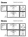
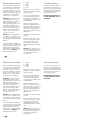
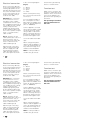
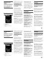
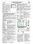
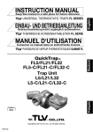
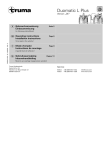
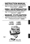
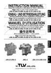
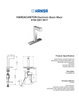
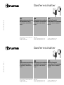
50020-13600 · 05/00 · 2’B+W · ©
Gasfernschalter
Gebrauchsanweisung Operating instructions Mode d’emploi
Einbauanweisung
Installation instructions Instructions de montage
Im Fahrzeug mitzuführen!
To be kept in the vehicle!
À garder dans le véhicule!
Seite 1
Page 3
Page 5
Truma Gerätetechnik GmbH & Co
Postfach 1252
D-85637 Putzbrunn
Service
Telefon +49 (0) 89 46 17-142
Telefax +49 (0) 89 46 17-159
e-mail: [email protected]
http://www.truma.com
Gasfernschalter
2
1
4
B
D
8
1
6
3
min. 50 cm
6
7
3
min. 50 cm
A
7
10
9
11
6
Duomatic
E
C
5
6
3
min. 50 cm
1
7
1 2
3 4
1 3 4
+
Triomatic
–
6
10
Gasfernschalter
2
1
4
B
8
6
7
3
min. 50 cm
6
3
min. 50 cm
D
1
7
10
9
11
6
Duomatic
E
C
5
6
1
3
7
min. 50 cm
A
1 2
3 4
1 3 4
Triomatic
+
10
–
6
TrumaGasfernschalter
Hauptabsperrventil für
die Gasversorgung,
vom Innenraum aus zu
bedienen
Die Gasflaschen bleiben
während der Nutzungsdauer
des Fahrzeuges geöffnet.
Wird die Gasversorgung
längere Zeit nicht benutzt,
sollten die Gasflaschen
geschlossen werden.
Gasversorgung
einschalten
Gebrauchsanweisung
Gasfernschalter
a
c
b
Am Bedienteil linken Schalter
(a) auf „Ein“. Betriebsanzeige
(c) leuchtet. Rechten Wippschalter (b) zum Öffnen kurz
antasten (um eine Überlastung der Magnetspule zu
vermeiden, nicht längere Zeit
auf der Wippe bleiben!).
Achtung: Bei einer Stromunterbrechung schließt das
Magnetventil und muß durch
kurzes Antasten des rechten
Wippschalters (b) neu eingeschaltet werden! Vor Dichtprüfung Gasfernschalter öffnen.
fernschalter aus dem Leitungssystem herausgeschraubt werden.
Technische Daten
Durchflußmenge: 1 kg/h
Gasrohranschluß
GS 8: Zapfen Ø 8 mm
GS 10: Zapfen Ø 10 mm
Max. Druck: 150 mbar
Nennspannung: 12 V DC
Stromverbrauch: 40 mA
kurzzeitig (Öffnen) 1 A
Schutzart: IP 54
Produkt-Ident-Nummer:
CE-0085AS0506
Ventilklasse: A, Gruppe 2
Umgebungstemperatur:
-20° C bis +60° C
Öffnungs- und Schließzeit:
< 1s
Einbaulage: beliebig
Schmutzsieb im Gaseingang
integriert.
Einbau und Reparatur des
Gasfernschalters darf nur
vom Fachmann durchgeführt werden.
Montage an die Einflaschen-Gasanlage
Bild A: Magnetventil (1) zwischen Gasschlauch (2) und
Gasleitung (3) montieren.
Montage an die Zweiflaschen-Gasanlage
Bild B, Truma-Duomatic:
T-Stück (4) an der Gasleitung
(3) abschrauben. Magnetventil (1) auf Gasleitung (3) montieren und T-Stück (4) am
Magnetventil (1) anschließen.
Bild C, Truma-Triomatic:
Gasleitung (3) am Anlagenregler (5) abschrauben. Magnetventil (1) auf Gasleitung
(3) montieren und Anlagenregler (5) am Magnetventil (1)
anschließen (evtl. mit einem
geeigneten Rohrschneider keine Säge - kürzen).
Gasversorgung
ausschalten
a = Schalter „Ein/Aus“
b = Starter
c = Betriebsanzeige
Einbauanweisung
Linken Schalter (a) auf
„Aus“. Betriebsanzeige (c)
erlischt. Bei Defekt oder
Stromausfall kann der Gas-
1
TrumaGasfernschalter
Hauptabsperrventil für
die Gasversorgung,
vom Innenraum aus zu
bedienen
Die Gasflaschen bleiben
während der Nutzungsdauer
des Fahrzeuges geöffnet.
Wird die Gasversorgung
längere Zeit nicht benutzt,
sollten die Gasflaschen
geschlossen werden.
Gasversorgung
einschalten
Gebrauchsanweisung
Gasfernschalter
a
c
a = Schalter „Ein/Aus“
b = Starter
c = Betriebsanzeige
b
Am Bedienteil linken Schalter
(a) auf „Ein“. Betriebsanzeige
(c) leuchtet. Rechten Wippschalter (b) zum Öffnen kurz
antasten (um eine Überlastung der Magnetspule zu
vermeiden, nicht längere Zeit
auf der Wippe bleiben!).
Achtung: Bei einer Stromunterbrechung schließt das
Magnetventil und muß durch
kurzes Antasten des rechten
Wippschalters (b) neu eingeschaltet werden! Vor Dichtprüfung Gasfernschalter öffnen.
Gasversorgung
ausschalten
Linken Schalter (a) auf
„Aus“. Betriebsanzeige (c)
erlischt. Bei Defekt oder
Stromausfall kann der Gas-
fernschalter aus dem Leitungssystem herausgeschraubt werden.
Technische Daten
Durchflußmenge: 1 kg/h
Gasrohranschluß
GS 8: Zapfen Ø 8 mm
GS 10: Zapfen Ø 10 mm
Max. Druck: 150 mbar
Nennspannung: 12 V DC
Stromverbrauch: 40 mA
kurzzeitig (Öffnen) 1 A
Schutzart: IP 54
Produkt-Ident-Nummer:
CE-0085AS0506
Ventilklasse: A, Gruppe 2
Umgebungstemperatur:
-20° C bis +60° C
Öffnungs- und Schließzeit:
< 1s
Einbaulage: beliebig
Schmutzsieb im Gaseingang
integriert.
Einbauanweisung
Einbau und Reparatur des
Gasfernschalters darf nur
vom Fachmann durchgeführt werden.
Montage an die Einflaschen-Gasanlage
Bild A: Magnetventil (1) zwischen Gasschlauch (2) und
Gasleitung (3) montieren.
Montage an die Zweiflaschen-Gasanlage
Bild B, Truma-Duomatic:
T-Stück (4) an der Gasleitung
(3) abschrauben. Magnetventil (1) auf Gasleitung (3) montieren und T-Stück (4) am
Magnetventil (1) anschließen.
Bild C, Truma-Triomatic:
Gasleitung (3) am Anlagenregler (5) abschrauben. Magnetventil (1) auf Gasleitung
(3) montieren und Anlagenregler (5) am Magnetventil (1)
anschließen (evtl. mit einem
geeigneten Rohrschneider keine Säge - kürzen).
1
Elektrischer Anschluß
Anschlußkabel (6) des Magnetventils mit Isolierband parallel zum Gasrohr (3) verlegen und nach innen zum vorgesehenen Platz für das Bedienteil (8) verlegen. Falls erforderlich, mit einem Kabel
3 x 0,75 mm2 verlängern.
Achtung: Der Anschluß der
Verlängerung darf nicht im
Flaschenkasten erfolgen! Für
Flaschenkasten-Durchführung (7) Gummitülle oder
Karosseriedichtmittel verwenden. Durchführung mindestens 50 cm über dem
Boden des Flaschenkastens oder in einem Schutzrohr
verlegt - vorsehen.
Bild D: Platz für das Bedienteil (8) an gut sichtbarer Stelle vorsehen. Loch Ø 10 mm
für die Kabeldurchführung (9)
bohren.
Anschlußkabel des Magnetventils (6) und 12 V Zuleitung
(10) von hinten durch die Kabeldurchführung (9) in der
Wand führen und gemäß Anschlußschema (Bild E) am
Bedienteil anklemmen.
1
2
3
4
=
=
=
=
braun
gelb
grün
weiß
Bedienteil mit den 2 beiliegenden Senkkopfschrauben
(11) befestigen.
Für die „Unterputz-Montage“ des Bedienteils liefert
Truma als Sonderzubehör
einen Bedienteilrahmen (Art.Nr. 39980-01).
Funktionsprüfung
Nach dem Einbau muß die
Dichtheit der Gasanlage geprüft werden. Anschließend
gemäß der Gebrauchsanweisung sämtliche Funktionen
des Gerätes prüfen.
Die Gebrauchsanweisung
ist dem Betreiber auszuhändigen!
Gerät am abgesicherten
Bordnetz (Zentralelektrik 5 10 A) mit Kabel 2 x 0,75 mm2
anschließen. Bei direktem
Anschluß an die Batterie ist
die Plus- und Minusleitung
abzusichern.
Alle Kabel mit Kabelschellen
sichern.
Bei Verwendung von Netzteilen ist zu beachten, daß
das Gerät nur mit Sicherheitskleinspannung nach
EN 60742 betrieben werden
darf.
Hinweis: Es ist auch möglich, den Gasfernschalter mit
einem Gaswarngerät oder
einem Hauptschalter zu
kombinieren.
2
Elektrischer Anschluß
Anschlußkabel (6) des Magnetventils mit Isolierband parallel zum Gasrohr (3) verlegen und nach innen zum vorgesehenen Platz für das Bedienteil (8) verlegen. Falls erforderlich, mit einem Kabel
3 x 0,75 mm2 verlängern.
Achtung: Der Anschluß der
Verlängerung darf nicht im
Flaschenkasten erfolgen! Für
Flaschenkasten-Durchführung (7) Gummitülle oder
Karosseriedichtmittel verwenden. Durchführung mindestens 50 cm über dem
Boden des Flaschenkastens oder in einem Schutzrohr
verlegt - vorsehen.
Bild D: Platz für das Bedienteil (8) an gut sichtbarer Stelle vorsehen. Loch Ø 10 mm
für die Kabeldurchführung (9)
bohren.
Anschlußkabel des Magnetventils (6) und 12 V Zuleitung
(10) von hinten durch die Kabeldurchführung (9) in der
Wand führen und gemäß Anschlußschema (Bild E) am
Bedienteil anklemmen.
2
1
2
3
4
=
=
=
=
braun
gelb
grün
weiß
Bedienteil mit den 2 beiliegenden Senkkopfschrauben
(11) befestigen.
Für die „Unterputz-Montage“ des Bedienteils liefert
Truma als Sonderzubehör
einen Bedienteilrahmen (Art.Nr. 39980-01).
Gerät am abgesicherten
Bordnetz (Zentralelektrik 5 10 A) mit Kabel 2 x 0,75 mm2
anschließen. Bei direktem
Anschluß an die Batterie ist
die Plus- und Minusleitung
abzusichern.
Alle Kabel mit Kabelschellen
sichern.
Bei Verwendung von Netzteilen ist zu beachten, daß
das Gerät nur mit Sicherheitskleinspannung nach
EN 60742 betrieben werden
darf.
Hinweis: Es ist auch möglich, den Gasfernschalter mit
einem Gaswarngerät oder
einem Hauptschalter zu
kombinieren.
Funktionsprüfung
Nach dem Einbau muß die
Dichtheit der Gasanlage geprüft werden. Anschließend
gemäß der Gebrauchsanweisung sämtliche Funktionen
des Gerätes prüfen.
Die Gebrauchsanweisung
ist dem Betreiber auszuhändigen!
TrumaGas remote switch
Main shut-off valve for
the gas supply is controlled from the inside
of the vehicle
The gas cylinders remain turned on while the vehicle is
being used.
If the gas supply is not to
be used for some time, the
gas cylinders should be
turned off.
Switching on the gas
supply
Switch left switch (a) on control panel to „On“. Operation
indicator lamp (c) lights up.
Briefly actuate right rocker
switch (b) to open (do not
operate the rocker too long
in order to avoid overloading
the solenoid!)
Operating
instructions
Gasfernschalter
a
c
b
a = switch "On/Off"
b = starter
c = operation indicator lamp
Attention: If there is a
power failure the solenoid
valve closes and has to be
reactivated by briefly actuating the right rocker switch
(b) again! Open gas remote
switch prior to checking for
leaks.
event of a defect or power
failure the gas remote switch
can be unscrewed from the
wiring system.
Technical data
Rate of flow: 1 kg/h
Gas pipe connection
GS 8: journal diameter 8 mm
GS 10: journal diameter
10 mm
Max. pressure: 150 mbar
Nominal Voltage: 12 V DC
Power consumption: 40 mA
briefly (for opening) 1 A
Protection system: IP 54
Product Ident. Number:
CE-0085AS0506
Class of the valve:
A, groupe 2
Ambiant temperatur:
-20 ° C to +60° C
Opening and closing time:
< 1s
Fitting Position: any
Dirt Filter integrated in gas
entrance.
Installation
instructions
Installation and repair of
the gas remote switch are
only to be carried out by
an expert.
Assembly in the
single-cylinder gas
system
Fig. A: Assemble solenoid
valve (1) between gas hose
(2) and gas line (3).
Assembly in the twocylinder gas system
Fig. B, Truma Duomatic:
Unscrew T-piece (4) from the
gas line (3). Mount solenoid
valve (1) on gas line (3) and
connect T-piece (4) to solenoid valve (1).
Fig. C, Truma Triomatic:
Unscrew gas line (3) at the
system regulator (5). Mount
solenoid valve (1) on gas line
(3) and connect system regulator (5) to solenoid valve (1)
(shorten using a pipe cutter,
if necessary - do not use a
saw).
Switching off the gas
supply
Switch left switch (a) to
"Off". Operation indicator
lamp (c) extinguishes. In the
3
TrumaGas remote switch
Main shut-off valve for
the gas supply is controlled from the inside
of the vehicle
The gas cylinders remain turned on while the vehicle is
being used.
If the gas supply is not to
be used for some time, the
gas cylinders should be
turned off.
Switching on the gas
supply
Switch left switch (a) on control panel to „On“. Operation
indicator lamp (c) lights up.
Briefly actuate right rocker
switch (b) to open (do not
operate the rocker too long
in order to avoid overloading
the solenoid!)
Operating
instructions
Gasfernschalter
a
c
b
a = switch "On/Off"
b = starter
c = operation indicator lamp
Attention: If there is a
power failure the solenoid
valve closes and has to be
reactivated by briefly actuating the right rocker switch
(b) again! Open gas remote
switch prior to checking for
leaks.
Switching off the gas
supply
Switch left switch (a) to
"Off". Operation indicator
lamp (c) extinguishes. In the
event of a defect or power
failure the gas remote switch
can be unscrewed from the
wiring system.
Technical data
Rate of flow: 1 kg/h
Gas pipe connection
GS 8: journal diameter 8 mm
GS 10: journal diameter
10 mm
Max. pressure: 150 mbar
Nominal Voltage: 12 V DC
Power consumption: 40 mA
briefly (for opening) 1 A
Protection system: IP 54
Product Ident. Number:
CE-0085AS0506
Class of the valve:
A, groupe 2
Ambiant temperatur:
-20 ° C to +60° C
Opening and closing time:
< 1s
Fitting Position: any
Dirt Filter integrated in gas
entrance.
Installation
instructions
Installation and repair of
the gas remote switch are
only to be carried out by
an expert.
Assembly in the
single-cylinder gas
system
Fig. A: Assemble solenoid
valve (1) between gas hose
(2) and gas line (3).
Assembly in the twocylinder gas system
Fig. B, Truma Duomatic:
Unscrew T-piece (4) from the
gas line (3). Mount solenoid
valve (1) on gas line (3) and
connect T-piece (4) to solenoid valve (1).
Fig. C, Truma Triomatic:
Unscrew gas line (3) at the
system regulator (5). Mount
solenoid valve (1) on gas line
(3) and connect system regulator (5) to solenoid valve (1)
(shorten using a pipe cutter,
if necessary - do not use a
saw).
3
Electrical connection
Route connecting cable (6)
of the solenoid valve with insulating tape parallel to the
gas pipe (3) and into the interior, to the intended location
of the control panel (8). Extend if necessary, using a
3 x 0.75 mm2 cable.
Attention: The connection
of the extension is not to
take place in the cylinder
compartment! For the cylinder compartment opening (7)
use a rubber sleeve or body
sealing compound. The
leadthrough opening must
be at least 50 cm above the
floor of the cylinder compartment - or routed inside a
cable conduit.
Fig. D: The place for the
control panel (8) is to be in a
position which is easy to
view. Drill a hole with a diameter of 10 mm for the
cable leadthrough (9).
Pass through connecting
cable of solenoid valve (6)
and 12 V supply line (10)
from behind, through the
cable duct and connect to
the control panel as shown
in the connecting diagram
(Fig. E).
1
2
3
4
=
=
=
=
brown
yellow
green
white
Fasten control panel using
the 2 enclosed countersunk
screws (11).
For concealed assembly of
the control panel a control
panel frame is available from
Truma, as special equipment
(Art. no. 39980-01).
switch with a gas warning
device or a main switch.
Function test
Make sure to check the gas
system for leaks after the installation. Then check all functions of the appliance as
specified in the operating instructions.
The operating instructions
must be handed over to
the user!
Connect appliance to fused
vehicle power supply (central
electrical system 5 - 10 A)
using a cable 2 x 0.75 mm2.
When connecting directly to
the battery, always fuse the
positive and negative lead.
Secure all cables with cable
clips.
When using power packs,
observe that the appliance is
only to be operated with safety extra-low voltage in accordance with EN 60742.
Note: It is also possible to
combine the gas remote
4
Electrical connection
Route connecting cable (6)
of the solenoid valve with insulating tape parallel to the
gas pipe (3) and into the interior, to the intended location
of the control panel (8). Extend if necessary, using a
3 x 0.75 mm2 cable.
Attention: The connection
of the extension is not to
take place in the cylinder
compartment! For the cylinder compartment opening (7)
use a rubber sleeve or body
sealing compound. The
leadthrough opening must
be at least 50 cm above the
floor of the cylinder compartment - or routed inside a
cable conduit.
Fig. D: The place for the
control panel (8) is to be in a
position which is easy to
view. Drill a hole with a diameter of 10 mm for the
cable leadthrough (9).
Pass through connecting
cable of solenoid valve (6)
and 12 V supply line (10)
from behind, through the
cable duct and connect to
the control panel as shown
4
in the connecting diagram
(Fig. E).
1
2
3
4
=
=
=
=
brown
yellow
green
white
Fasten control panel using
the 2 enclosed countersunk
screws (11).
For concealed assembly of
the control panel a control
panel frame is available from
Truma, as special equipment
(Art. no. 39980-01).
Connect appliance to fused
vehicle power supply (central
electrical system 5 - 10 A)
using a cable 2 x 0.75 mm2.
When connecting directly to
the battery, always fuse the
positive and negative lead.
Secure all cables with cable
clips.
When using power packs,
observe that the appliance is
only to be operated with safety extra-low voltage in accordance with EN 60742.
Note: It is also possible to
combine the gas remote
switch with a gas warning
device or a main switch.
Function test
Make sure to check the gas
system for leaks after the installation. Then check all functions of the appliance as
specified in the operating instructions.
The operating instructions
must be handed over to
the user!
Interrupteur à gaz
télécommandé
Truma
Robinet de fermeture
principal de l’alimentation en gaz pouvant
être commandé depuis l’habitacle
Pendant le temps de l’utilisation du véhicule, les bouteilles de gaz restent ouvertes.
Si l’alimentation en gaz
reste inutilisée sur une
période prolongée, il est
recommandé de refermer
les bouteilles.
Ouverture de l’alimentation en gaz
Tourner le commutateur gauche (a) de la pièce de commande sur „Marche“. Le témoin de fonctionnement (c)
s'allume. Pour ouvrir le robinet, actionner brièvement
le contact à bascule droit (b)
(pour éviter une surchauffe
de la bobine magnétique, ne
pas tenir trop longtemps le
contact enfoncé !).
Mode d’emploi
Gasfernschalter
a
c
b
a = interrupteur
„Marche/Arrêt“
b =starter
c = témoin de fonctionne
ment
Attention: En cas d’interruption du courant, l’électrovanne se ferme et il faut la rouvrir en actionnant brièvement
le contact à bascule droit (b)!
Avant un contrôle
d’étanchéité, ouvrir l’interrupteur à gaz télécommandé.
Fermeture de l’alimentation en gaz
Instructions de
montage
Tourner le commutateur gauche (a) de la pièce de commande sur „Arrêt“. Le témoin de fonctionnement (c)
s’éteint. En cas de défaut ou
de panne de courant, on peut
dévisser l’électrovanne du
système des conduites.
Le montage et les réparations de l’interrupteur à gaz
télécommandé ne doivent
être effectués que par un
spécialiste.
Caractéristiques
techniques
Débit: 1 kg/h
Raccordement au gaz
GS 8: téton Ø 8 mm
GS 10: téton Ø 10 mm
Pression max.: 150 mbar
Tension nominale: 12 V DC
Consommation en courant:
40 mA temporairement
(ouverture) 1 A
Type de protection: IP 54
N° d’ident. de produit CE:
CE-0085AS0506
Classification de la vanne:
A, groupe 2
Température ambiante:
de -20° C á +60°C
Temps d’ouverture et de
fermeture: < 1s
Position de montage:
quelconque
Filtre de poussière integré
dans l’entrée du gaz.
Montage sur l’installation à une bouteille
Fig. A : Monter l’électrovanne
(1) entre le flexible de gaz (2)
et la conduite de gaz (3).
Montage sur l’installation à deux bouteilles
Fig. B, Truma Duomatic:
Dévisser le raccord en T (4)
depuis la conduite de gaz (3).
Monter l’électrovanne (1) sur
la conduite de gaz (3) et brancher le raccord en T (4) sur
l’électrovanne (1).
Fig. C, Truma Triomatic:
Dévisser la conduite de gaz
(3) sur le détendeur de sortie
(5). Monter l’électrovanne (1)
sur la conduite de gaz (3) et
brancher le détendeur de sortie (5) à l’électrovanne (1) (si
5
Interrupteur à gaz
télécommandé
Truma
Robinet de fermeture
principal de l’alimentation en gaz pouvant
être commandé depuis l’habitacle
Pendant le temps de l’utilisation du véhicule, les bouteilles de gaz restent ouvertes.
Si l’alimentation en gaz
reste inutilisée sur une
période prolongée, il est
recommandé de refermer
les bouteilles.
Ouverture de l’alimentation en gaz
Tourner le commutateur gauche (a) de la pièce de commande sur „Marche“. Le témoin de fonctionnement (c)
s'allume. Pour ouvrir le robinet, actionner brièvement
le contact à bascule droit (b)
(pour éviter une surchauffe
de la bobine magnétique, ne
pas tenir trop longtemps le
contact enfoncé !).
Mode d’emploi
Gasfernschalter
a
c
a = interrupteur
„Marche/Arrêt“
b =starter
c = témoin de fonctionne
ment
b
Attention: En cas d’interruption du courant, l’électrovanne se ferme et il faut la rouvrir en actionnant brièvement
le contact à bascule droit (b)!
Avant un contrôle
d’étanchéité, ouvrir l’interrupteur à gaz télécommandé.
Fermeture de l’alimentation en gaz
Instructions de
montage
Tourner le commutateur gauche (a) de la pièce de commande sur „Arrêt“. Le témoin de fonctionnement (c)
s’éteint. En cas de défaut ou
de panne de courant, on peut
dévisser l’électrovanne du
système des conduites.
Le montage et les réparations de l’interrupteur à gaz
télécommandé ne doivent
être effectués que par un
spécialiste.
Caractéristiques
techniques
Débit: 1 kg/h
Raccordement au gaz
GS 8: téton Ø 8 mm
GS 10: téton Ø 10 mm
Pression max.: 150 mbar
Tension nominale: 12 V DC
Consommation en courant:
40 mA temporairement
(ouverture) 1 A
Type de protection: IP 54
N° d’ident. de produit CE:
CE-0085AS0506
Classification de la vanne:
A, groupe 2
Température ambiante:
de -20° C á +60°C
Temps d’ouverture et de
fermeture: < 1s
Position de montage:
quelconque
Filtre de poussière integré
dans l’entrée du gaz.
Montage sur l’installation à une bouteille
Fig. A : Monter l’électrovanne
(1) entre le flexible de gaz (2)
et la conduite de gaz (3).
Montage sur l’installation à deux bouteilles
Fig. B, Truma Duomatic:
Dévisser le raccord en T (4)
depuis la conduite de gaz (3).
Monter l’électrovanne (1) sur
la conduite de gaz (3) et brancher le raccord en T (4) sur
l’électrovanne (1).
Fig. C, Truma Triomatic:
Dévisser la conduite de gaz
(3) sur le détendeur de sortie
(5). Monter l’électrovanne (1)
sur la conduite de gaz (3) et
brancher le détendeur de sortie (5) à l’électrovanne (1) (si
5
nécessaire, raccourcir la conduite avec un coupe-tube pas de scie!).
Branchement
électrique
Installer le câble de branchement (6) de l’électrovanne
parallèlement à la conduite
de gaz (3) et l’amener à
l’intérieur jusqu'à l’emplacement prévu pour la pièce de
commande (8). Si nécessaire, le rallonger avec un câble
de 3 x 0,75 mm2.
Attention: Le branchement
de la rallonge ne doit pas
s'effectuer dans le caisson à
bouteille ! Pour la sortie du
caisson à bouteille (7), utiliser un passe-fil en caoutchouc ou du mastic
d’étanchéité pour carrosserie. Prévoir la traversée à au
moins 50 cm au-dessus du
fond du caisson à bouteille
ou dans un tube protecteur.
Fig. D: Prévoir l’emplacement pour la pièce de commande (8) en un endroit bien
visible. Percer un trou de
Ø 10 mm pour le passage du
câble (9).
Faire passer le câble de branchement de l’électrovanne
(6) et le câble d’alimentation
12 V (10) de l’arrière à travers le passe-câble et,
comme indiqué sur le schéma de branchement (fig. E),
le brancher à la pièce de
commande.
1
2
3
4
=
=
=
=
marron
jaune
vert
blanc
Fixer la pièce de commande
avec les 2 vis à tête fraisée
(11) jointes.
Pour un montage encastré
de la pièce de commande,
Truma livre en accessoire
spécial le cadre de pièce de
commande (no. de réf.
39980-01).
Si on utilise une alimentation
stabilisée, il faut observer
que l'appareil ne doit être
branché qu'à une petite tension de sécurité selon EN
60742!
Nota: Il est aussi possible de
combiner l’interrupteur à gaz
télécommandé à un appareil
d’alarme-gaz ou un interrupteur principal.
Contrôle de
fonctionnement
Après le montage, il faut
vérifier l’étanchéité du
système de gaz. Ensuite,
vérifier toutes les fonctions
de l'appareil au vu du mode
d’emploi.
Remettre le mode d’emploi
à l’utilisateur!
Brancher l'appareil, protégé
par un fusible (système électrique central 5 à 10 A), au
réseau de bord avec un
câble de 2 x 0,75 mm2. En
cas de branchement direct à
la batterie, protéger les fils
plus et moins.
Fixer tous les câbles avec
des colliers.
6
nécessaire, raccourcir la conduite avec un coupe-tube pas de scie!).
Branchement
électrique
Installer le câble de branchement (6) de l’électrovanne
parallèlement à la conduite
de gaz (3) et l’amener à
l’intérieur jusqu'à l’emplacement prévu pour la pièce de
commande (8). Si nécessaire, le rallonger avec un câble
de 3 x 0,75 mm2.
Attention: Le branchement
de la rallonge ne doit pas
s'effectuer dans le caisson à
bouteille ! Pour la sortie du
caisson à bouteille (7), utiliser un passe-fil en caoutchouc ou du mastic
d’étanchéité pour carrosserie. Prévoir la traversée à au
moins 50 cm au-dessus du
fond du caisson à bouteille
ou dans un tube protecteur.
Fig. D: Prévoir l’emplacement pour la pièce de commande (8) en un endroit bien
visible. Percer un trou de
Ø 10 mm pour le passage du
câble (9).
6
Faire passer le câble de branchement de l’électrovanne
(6) et le câble d’alimentation
12 V (10) de l’arrière à travers le passe-câble et,
comme indiqué sur le schéma de branchement (fig. E),
le brancher à la pièce de
commande.
1
2
3
4
=
=
=
=
marron
jaune
vert
blanc
Fixer la pièce de commande
avec les 2 vis à tête fraisée
(11) jointes.
Pour un montage encastré
de la pièce de commande,
Truma livre en accessoire
spécial le cadre de pièce de
commande (no. de réf.
39980-01).
Brancher l'appareil, protégé
par un fusible (système électrique central 5 à 10 A), au
réseau de bord avec un
câble de 2 x 0,75 mm2. En
cas de branchement direct à
la batterie, protéger les fils
plus et moins.
Fixer tous les câbles avec
des colliers.
Si on utilise une alimentation
stabilisée, il faut observer
que l'appareil ne doit être
branché qu'à une petite tension de sécurité selon EN
60742!
Nota: Il est aussi possible de
combiner l’interrupteur à gaz
télécommandé à un appareil
d’alarme-gaz ou un interrupteur principal.
Contrôle de
fonctionnement
Après le montage, il faut
vérifier l’étanchéité du
système de gaz. Ensuite,
vérifier toutes les fonctions
de l'appareil au vu du mode
d’emploi.
Remettre le mode d’emploi
à l’utilisateur!