1
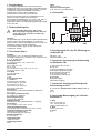
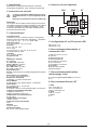
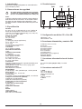
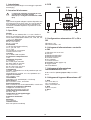
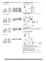
TDE Instruments GmbH
Gewerbestraße 8
D-71144 Steinenbronn
Version 2012-01
Tel.: +49(0)7157 20801
Fax: +49(0)7157 20813
Email: [email protected]
Web: www.tde-instruments.de
DPM802
Bedienungsanleitung
Instructions manual
Instructions d'utilisation
Manual de utilizacion
Istruzioni per l'uso
Digitalmultimeter für Schalttafeleinbau
Panel Mount Digital Multimeters
Multimètres Numériques montés sur bandeau
Multímetros digitales montados en panel
Voltamperometri digitali per montaggio su pannelli
Deutsch
English
Français
Español
Italiano
02
04
06
08
10
Beispiele
Examples
Exemples
Ejemplos
Esempi
12
12
12
12
12
RS232 Ausgang
RS232 output
Sortie RS232
Salida RS232
Uscita RS232
13
13
13
13
13
1. Beschreibung
3 3/4-stelliges digitales Volt- und Ampèremeter
Einbauinstrument mit LCD Anzeige, LED Beleuchtung,
zusätzlicher 40 Segment Bargraphanzeige, Low Bat
Anzeige und RS232 Schnittstelle. Instrument
konfigurierbar für AC oder DC Messung.
Dieses Instrument hat eine automatische
Bereichsumschaltung bei einem Messbereich von
400mV bis 300V, sowie einen wählbaren
Eingangsstrommessbereich von 1µA bis 10A. Min. &
max. Werte werden abgespeichert und können
abgerufen werden. Die Versorgungsspannung beträgt
5V bis 16V DC.
Höhe
bis zu 3000 m
Relative Luftfeuchtigkeit
max. 85% nicht kondensierend
4. Leiterplatte
CN3
CN2
ST
2. Sicherheitshinweise
!
3
Die maximale Spannung, die an den
Messeingängen angelegt werden darf ist
300V. INLO (0 V) ist intern an VSS (0 V)
angeschlossen.
2
97531
Hinweis:
Die Signalleitungen, die an dieses Gerät angeschlossen
werden, dürfen eine Gesamtlänge von 30m nicht
überschreiten. Werden Signalleitungen ausserhalb von
Gebäuden verlegt, müssen zusätzliche
Schutzmassnahmen gegen Surge Störimpulse
vorgesehen werden.
3. Technische Daten
Anzeige
Ziffernhöhe 11 mm; 40-Segment Balkenanzeige;
Vornullenunterdrückung; Low Bat; x10, x100, DC, AC,
µ, m, A, V, MIN, MAX
Eingangsbereich
± 0,1 mV bis 300 V; ± 0,1 µA bis 10 A
Genauigkeit
DC: V, µA, mA: ±1%
DC: A: ±3%
AC: 40–650 Hz: V, µA, mA: ±1%; A: ±3%
AC: 650–2700 Hz: ±5%
Linearität
± 0,1% Vollskala
Musterrate
1 Sek.
Eingangsimpedanz
V: 10 MOhm
0 bis 399,9 µA: 500 Ohm
400 bis 3999 µA: 50 Ohm
0 bis 39,9 mA: 5 Ohm
40 bis 399,9 mA: 0,5 Ohm
0 bis 10 A: 0,005 Ohm
Anschlüsse
Messeingang: Schraubanschlüsse für Kabel bis
zu 1,5 mm²
Versorgung und Steuerung
2 x 5-polig 0,1" Abstand
Steuerungseingänge
Nur Sink oder Kontakt
RS232-Ausgang
2400 Baud, 7 Bit, ungerade Parität, 1 Stoppbit
Versorgung
5 bis 16 VDC ± 10%, max. 15 mA
Hintergrundbeleuchtung
5 bis 8 VDC oder 12 VDC ±0.5V; max. 110mA
Installationskategorie (IEC 664)
Überspannungskategorie II
Verunreinigungsgrad 2 (IEC 64)
Betriebstemperatur
0°C bis +60°C
Lagertemperatur
-20°C bis +70°C
Umgebungsschutz
IP50
BL
10 8 6 4 2
SB
1
CN1
5. Konfigaration AC oder DC Messung an
Lötbrücke SB
SB offen = DC
SB geschlossen = AC
6. Anschluss Versorgung und Steuerung
an Stiftleiste CN1
1 VDD 5 VDC bis 16 VDC
2 VSS 0 V
3 Hintergrundbeleuchtung BL+
4 Hintergrundbeleuchtung BL5 Gemeinsame Steuerung
6 nicht angeschlossen
7 Gemeinsame Steuerung
8 MAX/MIN
9 RS232-Trigger
10 RS232-Ausgang
7. Anschluss Versorgung Hintergrundbeleuchtung an CN1
3 5 bis 8 VDC (Steckbrücke an BL setzen) oder 12
VDC.
40V
8. Anschluss Messeingang an Schraubklemmen ST
1: INHI
±0,1 mV bis 300,0 V
±0,1 µA bis 3999 µA
±0,01 mA bis 399,9 mA
2: INHI
±0,01 A bis 10,0 A
3: INLO
0V
02
9. Konfiguration Messbereich an CN2 und
CN3
10. Steuerungseingänge
Gemeinsame Steuerung (Pin 5 und 7) wird auf -3V
gehalten. NUR an Pin 8 oder 9 anschliessen.
±0.1mV - 300.0V
±0.1µA - 3999µA
11. RS232 Ausgang
Einen Widerstand wie nachstehend gezeigt extern
anschliessen.
±0.01mA - 399mA
12. RS232 Trigger
Einmal an gemeinsame Steuerung anschließen, um
den RS232-Datenstrom zu starten.
Zum Stoppen erneut an gemeinsame Steuerung
anschliessen.
13. MAX/MIN-Modus
±0.01A - 10A
0 aktueller Wert wird angezeigt
1 Zeigt vorherigen Höchstwert an
2 Zeigt vorherigen Mindestwert an
3 Zeigt aktuellen Wert an und beginnt mit der
Aufzeichnung neuer Höchst- und Mindestwerte
4 Zeigt neuen Höchstwert an.
5 Zeigt neuen Mindestwert an.
6 Zeigt aktuellen Wert an und beginnt mit der
Aufzeichnung neuer Höchst- und Mindestwerte.
usw.
beenden Beendet MAX/MIN-Modus und zeigt aktuellen
Wert an.
03
1. Introduction
4. PCB
3 3/4 digit volt- and ammeter with a 40 segment bargraph
indication, LCD display, LED backlight, low bat indication,
and RS232 interface.
The unit has a fully auto ranging voltage input to 300
V and a selectable 4 scale ammeter up to 10A. Powerded
by 5 VDC up to 16 VDC and annunciators for units on
display which include min. and max. functions. Unit can
be configured for AC or DC measurement.
CN2
CN3
ST
3
2. safety instructions
!
2
97531
The maximum voltage allowed for any
connection to the PCB is 300V.
INLO (0V) is internally connected to VSS
(0V)
Note:
Any signal cables connected to this device must not
exceed 30 metres in length.
If signal cables are installed that are routed outside the
building, it will be necessary to install additional surge
protection devices.
3. Specification
Display
Digits 11 mm; 40-Segment bargraph; Leading zero
blanking; Low Bat; x10, x100, DC, AC, µ, m, A, V, MIN,
MAX
Input Range
± 0,1 mV bis 300 V; ± 0,1 µA bis 10 A
Accuracy
DC: V, µA, mA: ±1%
DC: A: ±3%
AC: 40–650 Hz: V, µA, mA: ±1%; A: ±3%
AC: 650–2700 Hz: ±5%
Linearity
± 0,1% full scale
Sample Rate
1 sec.
Input impedance
V: 10 MOhm
0 bis 399,9 µA: 500 Ohm
400 bis 3999 µA: 50 Ohm
0 bis 39,9 mA: 5 Ohm
40 bis 399,9 mA: 0,5 Ohm
0 bis 10 A: 0,005 Ohm
Connections
Messeingang: Schraubanschlüsse für Kabel bis
zu 1,5 mm²
Power and control
2 x 5-way 0,1" spacing
Control inputs
Sink or contact only
RS232-output
2400 baud, 7 bit, odd parity, 1 stop bit
Supply
5 to 16 VDC ± 10%, max. 15 mA
Backlight supply
5 to 8 VDC or 12V DC ±0.5V; max. 110mA
Installation category (IEC 664)
Overvoltage category II
Pollution degree 2 (IEC 64)
Operating temperature
0°C to +60°C
Storage temperature
-20°C bis +70°C
Environmental protection
IP50
Altitude
Up to 3000 m
Relative Humidity
max. 85% non-condensing
BL
10 8 6 4 2
SB
1
CN1
5. Configuration AC or DC measuring at
solder strap SB
SB open = DC
SB shorted = AC
6. Connections Supply and control at socket
board at CN1
1 VDD 5 VDC to 16 VDC
2 VSS 0 V
3 Backlight supply BL+
4 Backlight supply BL5 Control common
6 not connected
7 Control common
8 MAX/MIN
9 RS232-trigger
10 RS232 output
7. Connection backlight supply at CN1
3 5 to 8 VDC (set jumper at BL) or 12 VDC.
40V
8. Connection Input at ST
1: INHI
±0,1 mV to 300,0 V
±0,1 µA to 3999 µA
±0,01 mA to 399,9 mA
2: INHI
±0,01 A to 10,0 A
3: INLO
0V
04
9. Configuration measuring range at CN2
and CN3
10. Control inputs
Control Common (pins 5 and 7) is held at –3V. Do NOT
connect to any pin except pins 8 and 9.
±0.1mV - 300.0V
±0.1µA - 3999µA
11. RS232 output
Connect a resistor externally as shown below.
±0.01mA - 399mA
12. RS232 trigger
Connect to Control common once to start the RS232
data stream.
Connect to Control common again to stop.
13. MAX/MIN-Mode
±0.01A - 10A
0 Displaying current value.
1 Displaying current value.
2 Displays previous minimum value.
3 Displays current value and starts recording new.
maximum and minimum values.
4 Displays new maximum value.
5 Displays new maximum value.
6 Displays current value and starts recording new.
maximum and minimum values etc.
exit Displays current value and starts recording new
maximum and minimum values.
05
1. Introduction
4. Cartes de circuits imprimés
Multimètres analogiques/numériques à sélection
automatique de gamme, pour montage sur panneau
CN2
2. Instructions de sécurité
!
CN3
ST
La tension maximale admissible pour tout
raccordement sur ce circuit imprimé est de
300V.
INLO (0 V) connectée en interne à VSS (0 V)
3
Remarque:
La longueur de tout câble mesure (signal) raccordé à
cet appareil ne doit pas excéder 30 mètres. Si les câbles
« mesure » passent à l'extérieur du bâtiment, il est
nécessaire d'installer des dispositifs additionnels de
protections de surtensions.
2
97531
1
3. Caractéristiques
Caractéristiques
Caractères 11 mm; Vumètre à barres, 40 segments;
Remise à zéro de conduction; Indicateurs : pile faible,
x10, x100, CC, CA, -, µ, m, A, V, MIN, MAX
Gamme d'entrée
± 0,1 mV à 300 V; ± 0,1 µA à 10 A
Précision
CC: V, µA, mA: ±1%
CC: A: ±3%
CA: 40–650 Hz: V, µA, mA: ±1%; A: ±3%
CA: 650–2700 Hz: ±5%
Linéarité
±0,1 % pleine échelle
Fréquence test
1 s.
Impédance d'entrée
V: 10 MOhm
0 à 399,9 µA : 500 Ohm
400 à 3 999 µA : 50 Ohm
0 à 39,9 mA : 5 Ohm
40 à 399,9 mA : 0,5 Ohm
0 à 10 A : 0,005 Ohm
Raccordements
Entrée : Connexions à vis protège-doigts pour fil jusqu'à
1,5 mm².
Alimentation et commande :
2 x 5 voies, espacement de 0,1"
Entrées de commande
Collecteur ou contact uniquement
Sortie RS232
2 400 bauds, 7 bits, parité impaire, 1 bit d'arrêt
Alimentation
5 à 16 VCC ±10 %, 15 mA max
Rétroéclairage
5 à 8 VCC / 12 VCC ±0.5V sélectionnable, 110 mA max.
Catégorie d'installation (IEC664)
Catégorie surtension II
Degré de pollution 2 (IEC 64)
Température de fonctionnement
0°C à +60°C
Température de stockage
-20°C à +70°C
Protection environnementale
IP50
Altitude
usqu'à 3 000 m
Relative Humidity
85 % max., sans condensation
BL
10 8 6 4 2
SB
CN1
5. Configuration AC ou DC mesure à SB
SB ouvert = CC
SB dérivés = CA
6. Raccordements Alimentation et
commande à CN1
1 VDD 5 V CC à 16 V CC
2 VSS 0 V
3 Rétroéclairage BL+
4 Rétroéclairage BL5 Commande, commune
6 non connectée
7 Commande, commune
8 MAX/MIN
9 Déclencheur RS232
10 Sortie RS232
7. Raccordements Alimentation
rétroéclairage à CN1
3 5 à 8 VCC (placer pont à BL) ou 12 VCC.
40V
8. Raccordements Entrée à ST
1: INHI
±0,1 mV à 300,0 V
±0,1 µA à 3999 µA
±0,01 mA à 399,9 mA
2: INHI
±0,01 A à 10,0 A
3: INLO
0V
06
9. Configuration Gamme d'entrée CN2 et
CN3
10. Entrées de commande
±0.1mV - 300.0V
Commande commune (broches 5 et 7) à -3 V. Ne PAS
connecter à quelque broche que ce soit, sauf aux
broches 8 et 9.
±0.1µA - 3999µA
11. Sortie RS232
Brancher une résistance en externe, comme indiqué
ci-dessous.
±0.01mA - 399mA
12. Déclencheur RS232
Brancher à la commande commune une fois, pour lancer
le flux de données RS232. Brancher de nouveau à la
commande commune pour arrêter.
13. Mode MAX/MIN
±0.01A - 10A
0 Affichage de la valeur actuelle
1 Affichage de la valeur maximale précédente
2 Affichage de la valeur minimale précédente
3 Affichage de la valeur actuelle et enregistrement des
nouvelles valeurs maximales et minimales
4 Affichage de la nouvelle valeur maximale.
5 Affichage de la nouvelle valeur minimale.
6 Affichage de la valeur actuelle et enregistrement des
nouvelles valeurs maximales et minimales. etcc
Quitter Quitte le mode MAX/MIN et affiche la valeur
actuelle.
07
1. Introducción
4. Circuito impreso
Multímetros analógicos/digitales con autocalibración
para montaje en panel
CN3
CN2
ST
2. Observaciones de seguridad
!
El voltaje máximo permitido para cualquier
conexión al circuito impreso es 300V. INLO
(0 V) va conectadointernamente a VSS (0 V)
3
Nota:
Cualquier cable de señal conectado a esta unidad no
debe de exceder de 30 metros. Si se instalan cables
de señal que sean llevados fuera del edificio, sera
necesario instalar unidades adicionales de protección
de onda.
2
97531
3. Especificación
Pantalla
61 mm x 18 mm; 4 caracteres de 11 mm; Gráfico de
barras de 40 segmentos; Se borran los ceros a la
izquierda; Anunciadores: batería baja, x10, x100, CC,
CA, -, µ, m, A, V, MÍN., MÁX
Rango de entrada
0,1 mV a 300 V
±0,1 µA a 10 A
Precisión
(±1 del dígito menos significativo)
CC: V, µA, mA: ±1%
CC: A: ±3%
CA: 40-650 Hz: como anterior
CA:650-2700 Hz: ±5%
Linearidad
±0,1% escala completa
Velocidad de muestreo
1 seg.
Impedancia de entrada
V: 10 MOhm
0 a 399,9 µA: 500 Ohm
400 a 3999 µA: 50 Ohm
0 a 39,9 mA: 5 Ohm
40 a 399,9 mA: 0,5 Ohm
0 a 10 A: 0,005 Ohm
Conexiones
Entrada: Conexiones tornillo a prueba de dedos para
cables de hasta 1,5 mm².
Alimentación y control: 2 x 5 vías 0,1 pulg. paso
Entradas de control
Sólo absorción o contacto
Salida RS232
2.400 baudios, 7 bits, paridad impar, 1 bit de parada
Alimentación
5 a 16 VCC ± 10%, 15 mA máx
Luz de fondo
5 a 8 VCC / 12 VCC ±0.5V seleccionable, 110 mA máx.
Categoría de instalación (IEC664)
Categoría II de sobrevoltaje
Grado de contaminación 2 (IEC64)
Temperatura de Funcionamiento
0° C a 60° C
Temperatura de almacenaje
-20° C a 70° C
Protección ambiental
IP50
Altitud
Hasta 3.000 m
Humedad relativa
85% máx. sin condensado
BL
10 8 6 4 2
SB
1
CN1
5. Configuración medición CC ó CA a SB
SB abierto = CC
SB acortados = CA
6. Conexiones alimentación y control a CN1
1 VDD 5 V CC a 16 V CC
2 VSS 0 V
3 Luz de fondo BL+
4 Luz de fondo BL5 Control común
6 no conectado
7 Control común
8 MÁX./MÍN. (ver la página 9)
9 Disparo RS232
10 Salida RS232
7. Conexiones alimentación luz de fondo a
CN1
3 5 a 8 VCC (usar jumper a BL) ó 12 VCC.
40V
8. Conexiones entrada a ST
1: INHI
±0,1 mV a 300,0 V
±0,1 µA a 3999 µA
±0,01 mA a 399,9 mA
2: INHI
±0,01 A a 10,0 A
3: INLO
0V
08
9. Configuración campo de medición a CN2
y CN3
10. Entradas de control
Control común (clavijas 5 y 7) mantenido a -3V. NO
conectar a ninguna clavija, excepto la clavijas 8 y 9.
±0.1mV - 300.0V
±0.1µA - 3999µA
11. Salida RS232
Conectar una resistencia externa como se indica a
continuación.
±0.01mA - 399mA
12. Disparo RS232
Conectar a control común una vez para comenzar el
tren de datos RS232.
Conectar a control común otra vez para detener.
13. Modo MÁX./MÍN.
±0.01A - 10A
0 Indica el valor actual.
1 Indica el valor máximo anterior.
2 Indica el valor mínimo anterior.
3 Muestra el valor actual y empieza a registrar los
nuevos valores máximos y mínimos.
4 Indica el nuevo valor máximo.
5 Indica el nuevo valor mínimo.
6 Muestra el valor actual y empieza a registrar los
nuevos valores máximos y mínimos.
etc.
salir Sale del modo MÁX./MÍN. e indica el valor actual.
09
1. Introduzione
4. PCB
Multimetri digitali/analogici con montaggio a pannello
autoranging
CN3
CN2
ST
2. Istruzioni di sicurezza
!
La tensione massima consentita per una
connessione su PCB è di 300V.
INLO (0 V) è collegato internamente a VSS
(0 V)
3
2
Nota:
Ogni cavo di segnale collegato a questo dispusitivo non
puo essere piu lungo di 30 metri. Se i cavi di segnale
sono installati su un percorso esterno all'edificio, è
necessario installare dispositivi di protezione di rete
addizionali.
97531
3. Specifiche
Display
61 mm x 18 mm; Altezza cifre 4 x 11 mm; Grafico a
barre con 40 segmenti; Zeri non significativi soppressi;
Annunciatori: livello batteria basso, x10, x100, CC, CA,
-, µ, m, A, V, MIN, MAX
Gamme di ingresso
da ±0,1 mV a 300 V
da ±0,1 µA a 10A
Accuratezza
(±1 la cifra significativa minima)
CC: V, µA, mA: ±1%
CC: A: ±3%
CA: 40-650 Hz: come sopra
CA:650-2700 Hz: ±5%
Linearità
±0,1% della scala completa
Frequenza di campionamento
1 sec.
Impedenza d'ingresso
V: 10 MOhm
da 0 a 399,9 µA: 500 Ohm
da 400 a 3999 µA: 50 Ohm
da 0 a 39,9 mA: 5 Ohm
da 40 a 399,9 mA: 0.5 Ohm
da 0 a 10 A: 0.005 Ohm
Collegamenti
Ingresso: collegamenti con viti di protezione per cavi
fino a 1,5 mm²
Alimentazione e controllo: 2 x 5 vie, spaziatura 0,1"
Ingressi di controllo
Solo contatto o sink
Uscita RS232
2400 baud, 7 bit, parità dispari, 1 bit di stop
Alimentazione
da 5 a 16 VCC ± 10%, 15mA max
Retroilluminazione
da 5 a 8 VCC/12 VCC ±0.5V selezionabile, 110 mA max
Categoria di installazione (IEC664)
Categoria di sovratensione II
Grado di inquinamento 2 (IEC 64)
Temperatura di funzionamento
da 0°C a +60°C
Temperatura di immagazzinaggio
-da 20°C a +70°C
Protezione ambientale
IP50
Altitudine
Fino a 3000 m
Umidità relativa
85% max (senza condensa)
BL
10 8 6 4 2
SB
1
CN1
5. Configurazione misurazione CC o CA a
SB
SB aperto = DC
SB cortocircuitato = AC
6. Collegamenti alimentazione e controllo
a CN1
1 VDD da 5 VCC a 16 VCC
2 VSS 0 V
3 Retroilluminazione BL+
4 Retroilluminazione BL5 Controllo comune
6 Non collegato
7 Controllo comune
8 MAX/MIN (vedere pagina 10)
9 Trigger RS232
10 Uscita RS232
7. Collegamenti alimentazione
retroilluminazione a CN1
3 da 5 a 8 VCC (Usare jumper a BL) a 12 VCC.
40V
8. Collegamenti ingresso Misurazione a ST
1: INHI
±0,1 mV a 300,0 V
±0,1 µA a 3999 µA
±0,01 mA a 399,9 mA
2: INHI
±0,01 A a 10,0 A
3: INLO
0V
10
9. Configurazione gamme di misurazione
a CN2 e CN3
10. Ingressi di controllo
Il controllo comune (pin 5 e 7) viene mantenuto a -3 V.
Collegare SOLO ai pin 8 e 9.
±0.1mV - 300.0V
11. Uscita RS232
±0.1µA - 3999µA
Collegare un resistore esterno, come mostrato di seguito.
±0.01mA - 399mA
12. Trigger RS232
Collegare al controllo comune una volta avviato il flusso
di dati RS232.
Collegare nuovamente al controllo comune per arrestare.
13. Modalità MAX/MIN
±0.01A - 10A
0 Visualizza il valore corrente.
1 Visualizza il valore massimo precedente.
2 Visualizza il valore minimo precedente.
3 Visualizza il valore corrente e avvia la registrazione
dei nuovi valori massimo e minimo.
4 Visualizza il nuovo valore massimo.
5 Visualizza il nuovo valore minimo.
6 Visualizza il valore corrente e avvia la registrazione
dei nuovi valori massimo e minimo.
ecc.
exit Esce dalla modalità MAX/MIN e visualizza il valore
corrente.
11
Beispiele
Examples
Exemples
Ejemplos
Esempi
DC
AC
12
1. Serial Data output
3. Range
The serial data is sent to the data output pin (pin 10)
twice every A/D conversion cycle. The data format
complies with JIS 7BIT transmission code with a baud
rate of 2400. The host can use the RS232 interface to
read the data. A single data packet allows a start bit
(always 0), 7 data bits, an odd parity check bit, and a
stop bit (always 1). The high and low voltage levels
correspond to +V and -3V respectively. The serial output
remains at 1 (high) when it is inactive. Hence the start
bit (0) could be used as the triggering signal to begin
the reading process. The following figure shows the
data format of a single packet. The LSB is sent first
and the MSB is sent last.
This packet indicates the full scale range of the meter.
When the meter is in current mode (A) this packet is
always 0110000 since the full scale range in this mode
is fixed. The following table shows the codes for each
range.
0
1
LSB
MSB
One data block consists of 11 packets, or 110 bits. The
following figure shows the format of a data block. The
range packet indicates the full scale range of the meter.
Digit 3 through to digit 0 represent the digits on the
meters display. The function packet indicates the
measurement mode of the meter. Status, option 1, and
option 2 give the status of the meter. CR and LF are
delimiters used to separate the blocks.
0
10
range
0
10
digit3
10
digit1
0
10
10
0
1
function
10
option1
10
CR
digit2
digit0
status
1
1
option2
1
LF
The meter always outputs the current input value to the
serial port regardless of whether the hold function has
been activated or not. Each block is repeated twice in
one conversion cycle. The detailed data format of each
packet is listed below.
2. Function
This packet indicates the measurement mode of the
meter. The following table summarises the transmitted
code for each mode. Note that the encoding of this
packet is different to the encoding of the FC1 to FC4
switch.
Code
0111011
0111101
0111001
0111111
0111110
0111100
0111000
0111010
Measurement Mode
Voltage
µA Current
mA Current
A Current
ADP0
ADP1
ADP2
ADP3
Code
0110000
0110001
0110010
0110011
0110100
0110101
V
400.0 mV
4.000 V
40.00 V
400.0 V
4000 V
mA
40.00 mV
400.0 mA
µA
400.0 µA
4000 µA
4. Digit 3 to digit 0
Digit 3 is the most significant digit on the LCD panel,
and the digit 0 is the least significant digit. When the
LCD panel shows OL the serial port outputs 4000.
Digit
0
1
2
3
4
5
6
7
8
9
Code
110000
110001
110010
110011
110100
110101
110110
110111
111000
111001
5. Status
The format of this packet is shown below. (The judge
field is not applicable to these units, but will be present
in the data field- it should be disregarded). The sign
field indicates whether the minus sign on the LCD is
ON or OFF. The Batt field indicates if the battery low
condition is true. OL indicates input overflow.
0
1
1 Judge Sign BATT OL
Bit 6 Bit 5 Bit 4 Bit 3 Bit 2 Bit 1 Bit 0
6. Option 1
This packet contains information on special measurement
modes. The format of this packet is shown below. The
three none constant fields are set to "1" when the meter
operates in the corresponding special modes, max and
min. Bit 0 (VAHZ) is not applicable.
0
1
1 Pmax Pmin
0 VAHZ
Bit 6 Bit 5 Bit 4 Bit 3 Bit 2 Bit 1 Bit 0
13
7. Option 2
This packet contains information on the operating mode
of the meter. The format of this packet is shown below.
The DC field indicates that the meter operates in DC
mode, measuring voltage or current.
The AC mode indicates that the meter operates in AC
mode, measuring voltage or current. The APO field is
not applicable.
0
1
1
Bit 6 Bit 5 Bit 4
DC
Bit 3
AC AUTO APO
Bit 2 Bit 1 Bit 0
8. CR
Carriage Return. The transmitted code is 0001101
9. LF
Line Feed. The transmitted code is 0001010
14
Abmessungen
Dimensions
Dimensiones
Dimensioni
PANEL CUT-OUT
33 x 68mm +0.5 / -0.0
(1.3 x 2.68”'94 +.02 / -0.0)
15
TDE Instruments GmbH
Gewerbestraße 8
D-71144 Steinenbronn
Tel.: +49(0)7157 20801
Fax: +49(0)7157 20813
Email: [email protected]
Web: www.tde-instruments.de