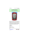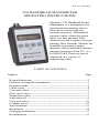
1
File No. 350:440-2
350 HANDHELD MANOMETER
OPERATING INSTRUCTIONS
Meriam’s 350 Handheld Smart
Manometer is a microprocessor
based pressure sensing device
that can be used to directly
measure pressure. Differential
pressure units (clean dry gases
only) can also measure flow
when used with a square root type
primary flow element. Models are
available to measure gauge,
absolute, differential and vacuum
pressure in ranges from 20” w.c.
to 2000 PSIG. Pressure can be
displayed in a variety of
engineering units.
TABLE OF CONTENTS
Subject
Page
Keypad functions --------------------------------------------------- 2
Pressure zeroing the manometer ----------------------------------- 3
Program mode-------------------------------------------------------- 4
Units select ----------------------------------------------------------- 4
User unit select ------------------------------------------------------ 5
Flow unit select ------------------------------------------------------ 7
Damp rate select ---------------------------------------------------- 8
Auto shut off --------------------------------------------------------- 9
User info select -----------------------------------------------------10
Contrast select ------------------------------------------------------12
Specifications -------------------------------------------------------13
Resolution -----------------------------------------------------------14
Changing the battery -----------------------------------------------15
Recalibration --------------------------------------------------------15
KEYPAD FUNCTIONS
ON/OFF & BACKSPACE KEY
Turns the manometer on into the Measure Mode
and then turns the unit off from the Measure
Mode. Also serves as a backspace key when
editing in the Program Mode. The backspace
function takes the user out of a programmable
register without changing the previous setting. Pressing this
key repeatedly will return the user to the Measure Mode
and then shut off the manometer.
MIN/MAX & UP ARROW KEY
In the Measure Mode activates the Min/Max
function of the manometer. When activated the the
minimum value is displayed on the upper left of
the display and the maximum value on the upper
right. Min/Max values on the display are updated
every 0.1 seconds. This key also deactivates this function.
Up arrow key is used to scroll through the programmable
registers when the unit is in the Program Mode. Once a
programmable register is selected the up arrow
can be
used to edit that register.
HOLD & DOWN ARROW KEY
In the Measure Mode activates and deactivates the display
Hold function. This is designed to freeze a value
being displayed. If the MIN/MAX function is
activated, those values are also frozen. With
HOLD activated, the letter “H” appears in the
lower left of the display. Down arrow function
is used to scroll through programmable registers with the
unit in the Program Mode. Once a programmable register
is selected the down arrow can be used to edit that
register.
PRGM & ENTER KEY
Puts the manometer into the Program Mode from
the Measure Mode. When in the Program
Mode, pressing this key selects the programmable
register to be edited. After the register has been
edited, pressing the PRGM key enters the new
setting into the manometer’s non-volatile memory. This key
also acts as a forward space key when editing user input
such as the header name.
2
PRESSURE ZEROING THE MANOMETER
Prior to making a pressure measurement, the 350 Smart
Manometer should be zeroed for pressure. This will
eliminate any zero drift that has occurred since the
manometer was last used. To zero the manometer, starting
with the unit turned off, follow this key stroke sequence:
Keystroke
Display
1. Press ON/OFF button.
The display briefly shows the
header name and full scale
range of the unit in the last
engineering units selected.
The manometer then goes
into the Measure Mode
where the applied pressure
and engineering unit of
measure are displayed.
Display should read close to
zero. (See note below)
2. Turn off pressure
sources and vent
pressure ports to
atmosphere.
Top line of display reads
“ZERO IN PROGRESS”
while bottom line counts
down from 9. Zeroing is
complete when unit returns
to Measure Mode.
3. Press MIN/MAX and
HOLD keys at the same
time. (See figure 1)
Note: All Models and ranges
can be zeroed only if the new
Zero is within ± 5% of the
original factory calibration
zero. If outside this limit a
“ZERO ERROR” message
appears and the manometer
will not zero.
Figure 1.
3
PROGRAM MODE
The Program Mode is used to configure the manometer
for Measure Mode operation. The configurable registers
that are found in the Program Mode are Units Select,
Damp Rate Select, User Info Select, Contrast Select and
Exit. The manometer can be put into the Program Mode at
any time during Measure Mode operation by pressing the
PRGM key. The top line of the display will read
“PROGRAM MODE”. The bottom line will read “UNITS
SELECT”. Press the up or down arrow keys to scroll
through the Program Mode to the desired register.
UNITS SELECT
The standard engineering units available on the Smart
Manometer are:
1. PSI
2. Inches of Water at 20° Celsius
3. Inches of Water at 60° Fahrenheit
4. Inches of Water at 4° Celsius
5. Kg/ cm2
6. Kilopascals
7. Millibars
8. Bars
9. Centimeters of Water at 20° Celsius
10.Inches of Mercury at 0° Celsius
11.Millimeters of Mercury at 0° Celsius
12.User unit select. (see page 5)
13.Flow units. (see page 7)
To change engineering unit of measure the manometer
should be “ON” and in the Measure Mode. Then follow
the following steps:
Keystroke
Display
1. Press PRGM key.
Top line reads “PROGRAM
MODE” and bottom line
reads “UNITS SELECT”.
2. Press PRGM key
Top line reads “UNITS
SELECT” and bottom shows
current engineering units
4
3. Press up or down
arrow key until desired
engineering unit is
displayed.
Engineering units on bottom
line of display change.
4. Press the PRGM key to
select engineering unit.
Top line reads “PROGRAM
MODE” and bottom line
reads “UNITS SELECT”.
Bottom line reads “EXIT”
5. Press the down arrow
key.
Display returns to Measure
Mode in new engineering
units.
6. Press PRGM key.
USER UNIT SELECT
Engineering units not included in the standard selection can
be programmed into the manometer using the Units Select
register in the Program Mode. This is done by an internal
microprocessor that multiplies the applied pressure in the
base factory calibration units by the value in the user unit
register. For example, 1 PSI equals 2.30894 Feet of Water
at 60° F. A 20 PSI manometer can be programmed to read
out in Feet of Water using the following steps:
Keystroke
Display
1. Follow steps 1-3 in
“Units Select” (pg. 4)
until “USER UNIT
SELECT” is displayed.
Reads “USER UNIT
SELECT” on the bottom line.
2. Press PRGM key. (see
Note: on pg. 7)
Reads “VALUE=” on the top
line and “CHANGE?: YES”
on the bottom line.
3. To change the value
press the PRGM key.
Top line reads “USER UNIT
VALUE”.
5
4. Press the up arrow
key until the first digit
reads “2”.
Top line reads “USER UNIT
VALUE” Bottom line reads
“20000000”. (new units)
5. Press the right arrow
key to enter this value
and advance the cursor
to the next digit.
Cursor flashes to the right of
“2”. (Numbers 0-9, decimal
point or a blank space can be
displayed.)
6. Repeat steps 4 and 5
until the bottom line of
the display reads
2.30894.
Bottom line reads “2.30894”
Last digit “4” is blinking.
7. If an error is made use
the back space key to
move the cursor back to
the incorrect digit. Press
the up or down
arrow keys to display the
correct value.
8. Press the PRGM key
Top line reads “VALUE =”.
until the display changes. Bottom line reads
(see Note: on pg. 7)
“CHANGE?: YES”.
9. Press the PRGM key.
Top line reads “USER UNIT
NAME”.
10.Follow steps 4-6 above
to enter “FT H2O”
Bottom line reads “FT
H2O”. (A-Z, 0-9, decimal
point or a blank space can be
displayed.)
11. Press PRGM key.
Top Line reads “PROGRAM
MODE” and bottom line
reads “UNITS SELECT”.
Bottom line reads “EXIT”.
12. Press down arrow key.
Manometer returns to
Measure Mode. Display
shows “FT H2O”.
13. Press PRGM key.
6
Note: If at steps 2 and 8 the “VALUE =” is the desired
value or description, press the up or down key. This
will toggle the bottom line from the default “CHANGE?:
YES” to “CHANGE?: NO”. Follow steps 11-13 on page 6
to return to the Measure Mode.
FLOW UNIT SELECT
Differential Pressure Smart Manometers can be
programmed to read out in flow measurement units such as
CFM or Lit/min. This use is limited to clean, dry, noncorrosive gases. The primary element has to be a
differential pressure producing, square root type device
such as a pitot tube, orifice plate or venturi.
The flow constant and flow units description are
programmed into the manometer using the same keystrokes
used in User Unit Select programming. At step 1 choose
Flow Unit Select instead of User Unit Select.
The formula used in calculating the flow rate is:
½
Fc = Q ÷ DP
Where
Q = Flow rate
Fc = Flow constant
DP = Differential Pressure (in. H2O at 20°C)
Example: If the DP is 25 in. H2O when the flow rate is
10,000 SCFM, the Flow constant equals 2,000.
7
DAMP RATE SELECT
Adjustable damping is available to steady the display when
measuring pulsating pressure or flow. The Smart
Manometer has a range of damping rates of 0.1, 0.2, 0.5, 1,
2, 5, 10, and 25 seconds. Damping is done by averaging
new data from the pressure sensor against previously
collected data. The microprocessor collects data from the
sensor every 0.1 seconds. The display updates every 0.5
seconds, showing the current 0.1 second pressure reading.
When set at 25 seconds, the display updates every 0.5
seconds with the average of the previous 25 seconds
readings. Therefore, it takes up to 25 seconds from the time
pressure is applied until the manometer displays the full
scale applied pressure. Min/Max display updates every 0.1
seconds.
To set the damp rate:
Keystroke
Display
1. Follow steps on page 4 to Top line reads “PROGRAM
MODE” bottom line reads
put the unit in Program
“UNITS SELECT”.
Mode.
2. Press the up
key.
arrow
Bottom line reads “DAMP
RATE SELECT”.
3. Press the PRGM key.
Top line reads “DAMP
RATE SELECT”.
4. Press the up or down
arrow keys until the
desired damp rate is
displayed on bottom line.
Bottom line shows damp
rate in seconds.
5. Press the PRGM key.
Top line reads “PROGRAM
MODE” bottom line reads
“UNITS SELECT”.
6. Press the down arrow
key.
Bottom line reads “EXIT”.
7. Press the PRGM key.
Returns to Measure Mode.
8
AUTO SHUT-OFF
Enabling the Auto Shut-Off feature allows the manometer
to turn itself off after approximately ten minutes of keypad
inactivity. Disabling this feature limits the manometer to
being turned off by using the ON/OFF key only. Units are
shipped from the factory with the Auto Shut-Off enabled.
To configure the auto shut-off follow the steps below.
Keystroke
Display
1. Follow steps 1-7 on page
10.
Top line reads “AUTO
SHUT-OFF” bottom reads
“ENTER TO SELECT”.
2. Press the PRGM key.
Bottom line reads
“ENABLED” or
“DISABLED”.
3. Press the up or down
arrow keys.
Auto Shut-Off status on
bottom line changes.
4. Press the PRGM key.
Top line reads “HEADER
NAME” bottom line shows
header.
5. If Header needs to be
edited follow steps 11-17
on pages 11.
Changes Header and returns
to Measure Mode.
6. If header is correct follow Returns to Measure Mode.
steps 8-10 on page 11.
9
USER INFO SELECT
The User Info Select register is designed to provide the
user with information on the hardware and software in the
manometer. This register stores information on the sensor’s
serial number, software version, date of last calibration,
Auto Shut-Off status and the instrument Start-Up Header.
The Start Up Header appears whenever the manometer is
turned on. Below the Header is the Full Scale of the
manometer, in the last engineering units programmed. The
factory setting of the header is “MERIAM INSTR.”. This
can be edited to show a custom alpha-numeric string as
required by the user.
To configure the Unit Info Select register follow the
keystrokes listed below.
Keystroke
Display
1. From the Measure
Mode, press the PRGM
key
Top line reads “PROGRAM
MODE”. Bottom line reads
“UNITS SELECT”
2. Press the up
two times.
arrow key Bottom line changes to
“USER INFO SELECT”
3. Press the PRGM key.
Bottom line shows serial
number.
4. Press the PRGM key.
Software version number
shown.
5. Press the PRGM key.
Calibration Date shown.
6. Press the PRGM key.
Top line reads “AUTO
SHUT OFF” bottom line
reads “ENTER TO
SELECT”
7. Instructions for setting
the AUTO SHUT-OFF
are on page 9. Press up
arrow key to proceed
to editing the Header.
Top line reads “HEADER
NAME” bottom line reads
“MERIAM INSTR.”. Cursor
flashes at bottom left.
10
8. If header is correct press Top line reads “PROGRAM
backspace
key . If
MODE”. Bottom reads
editing is desired proceed “USER INFO SELECT”
to step 11.
9. Press up arrow key
two times.
Bottom line reads “EXIT”.
10. Press the PRGM key.
Returns to Measure Mode.
11. Press the up or down
arrow keys to set
correct alpha-numeric
value.
Displays a number between
0 and 9, a letter from A to
Z, / or a blank space.
12. Press right arrow
accept entry.
Cursor advances one space
to right.
to
13. Repeat steps 11 and 12
until the desired Header
is shown.
14. If an error is noted press
the back arrow key
until cursor is over the
incorrect value. Follow
step 11 to correct. Press
the right arrow to
advance the cursor
without changing values.
14. When header is
complete press the
PRGM key to advance
cursor to end of bottom
line.
Cursor flashes at bottom
right.
15. Press the PRGM key.
Top line reads “PROGRAM
MODE” bottom reads
“UNITS SELECT”.
16. Press down arrow key
Bottom line reads “EXIT”.
17. Press the PRGM key.
Returns to Measure Mode.
11
CONTRAST SELECT
The Contrast Select register allows the user to adjust the
character contrast of the LCD display to provide the best
visibility for the ambient conditions. If during the contrast
adjustment an error is made pressing the backspace key
returns the display to the previous contrast setting. To
adjust the contrast follow the keystrokes below:
Keystroke
Display
1. From the Measure
Mode press the PRGM
key.
Top line reads “PROGRAM
MODE” bottom reads
“UNITS SELECT”.
2. Press the up arrow key
three times.
Bottom line reads
“CONTRAST SELECT”.
3. Press the PRGM key.
Top line reads
“CONTRAST SELECT”
bottom line shows a
numerical value.
4. Press up or down
arrow keys to increase or
decrease the contrast
value. A low number
gives maximum contrast
and a high number gives
minimum contrast.
LCD lightens or darkens
depending on value set.
5. Press the PRGM key.
Top line reads “PROGRAM
MODE” bottom reads
“UNITS SELECT”.
6. Press down
arrow key. Bottom line reads “EXIT”.
7. Press the PRGM key.
Returns to Measure Mode.
12
SPECIFICATIONS
Type and Range:
DN: Differential Non-Isolated 20“, 200”, 2000” H20
GI: Gauge Isolated 20 PSI, 200 PSI, 2000 PSI
AI: Absolute Isolated 900, 2000 mm Hg
Accuracy:
350 Test Gauge: ±0.05 % of Full Scale
351 Calibrator: ±0.025 % of Full Scale -5°C to 50°C
±0.05% of Full Scale -20°C to -5°C
-DN0020 versions have only ±0.1 % of Full Scale
Includes the combined effects of temperature, linearity,
repeatability, hysteresis and resolution. NIST
certification supplied with manometer.
Temperature:
Storage:
-40° F to 140° F (-40° C to 60° C)
Operating: -4° F to 122° F (-20° C to 50° C)
Media Compatibility: Non-isolated sensors for use with
clean, dry non-corrosive gases only. Isolated sensors for all
fluids compatible with 316SS.
Pressure Limits: 2 × range on GI and AI units. 2 × range on
DN units when pressurized on high side only; 150 PSI
(10.5 Kg/cm²) static when applied to both sides of sensor
simultaneously.
Connection: 1/8” female NPT, 316SS. AI and GI models
have 1 pressure port only (P1). DN models have 2 pressure
ports. P1 is the high pressure connection and P2, the low
pressure connection.
Power: 9 volt battery, lithium or alkaline, field replaceable.
Lithium is recommended for operation below 32° F (0° C).
Display: 5 significant digit LCD
Enclosure: 14 oz. ABS plastic (6.5” × 3.6” × 2,25”)
CSA units: Intrinsically safe for Class 1, Groups A, B, C,
and D.
13
14
XX.XXX
XX.XXX
XX.XXX
XX.XXX
XX.XXX
XX.XXX
Kg/cm²
inH20 4°C
inH20 60°F
inH20 20°C
PSI
XX.XXX
Bar
XX.XXX
XX.XXX
cm H20
KPa
XX.XXX
in. Hg
mBar
XX.XXX
mm Hg
20” WC
XXX.XX
XXX.XX
XXX.XX
XXX.XX
XXX.XX
XXX.XX
XXX.XX
XXX.XX
XXX.XX
XXX.XX
XXX.XX
200” WC
XXXX.X
XXXX.X
XXXX.X
XXXX.X
XXXX.X
XXXX.X
XXXX.X
XXXX.X
XXXX.X
XXXX.X
XXXX.X
2000” WC
XX.XXX
XXX.XX
XXX.XX
XXX.XX
XX.XXX
XX.XXX
XXX.XX
XX.XXX
XXX.XX
XX.XXX
XXX.XX
20 PSI
RESOLUTION
XXX.XX
XXXX.X
XXXX.X
XXXX.X
XXX.XX
XXX.XX
XXXX.X
XXX.XX
XXXX.X
XXX.XX
XXXX.X
200 PSI
XXXX.X
XXXXX
XXXXX
XXXXX
XXXX.X
XXXX.X
XXXXX
XXXX.X
XXXXX
XXXX.X
XXXXX
2000 PSI
XXX.XX
XXXX.X
XXXX.X
XXXX.X
XXX.XX
XXX.XX
XXXX.X
XXX.XX
XXXX.X
XXX.XX
XXXX.X
900mm Hg
XXX.XX
XXXX.X
XXXX.X
XXXX.X
XXX.XX
XXX.XX
XXXX.X
XXX.XX
XXXX.X
XXX.XX
XXXX.X
2000mm Hg
CHANGING THE BATTERY
The manometer is powered by one 9 volt battery. When the
output of the battery under load drops below 6.5 volts the
display will alternate between “LOW POWER DETECT”
and “REPLACE BATTERY”.
To replace the battery locate the battery compartment in the
bottom rear of the manometer. Push down on the small
rectangular area in the battery cover. While pushing the
cover down, slide the cover out the bottom of the unit. Pull
the battery connector off the battery terminals. Plug the
new battery into the connector and install in the
compartment. Slide the battery cover on until the locking
clip goes into the manometer housing and the channels on
the bottom of the cover are locked in place.
RECALIBRATION
The Smart Manometer’s accuracy can be verified by using
a ± 0.015% of reading deadweight tester. It is
recommended that the manometer be checked at a
minimum of four test points at 25%, 50%, 75% and 100%
of the units range. A full ten point evaluation provides the
most complete information on the manometers
performance.
Before performing the evaluation there are several
corrections to the deadweight tester that may have to be
made.
1. Use the User Unit Select option in Program Mode to
match the Smart Manometer units to the deadweight tester
units. Be sure to match the Smart Manometer temperature
reference to the temperature reference of the deadweight
tester (for in.H2O and Hg units only).
2. Correct the deadweight tester readings for ambient
temperature if it is different from the reference
temperature. The Smart Manometer does this
automatically.
15
3. The local gravity at location where the evaluation is
being performed must be corrected for on the deadweight
tester. Standard gravity reference is 980.665 cm/sec/sec.
This gravity occurs at 45° north latitude, at sea level.
4. Make sure there are no leaks in the system.
The 200” and 2000” in.H2O Smart Manometers have a
calibration reference of inches of water at 20°C. The 2000
mm Hg absolute manometer references mercury at 0°C.
The 20, 200 and 2000 PSI manometers are calibrated in
PSI and therefore do not have a reference temperature. The
effects of local gravity on the Smart Manometer are
corrected for by zeroing the manometer (see pg. 3) before
the evaluation.
This evaluation will confirm whether the manometer is or
is not operating within its accuracy specification at the
temperature that the evaluation was performed at only. This
does not guarantee that the manometer is within it’s
accuracy specification at other temperatures.
If the manometer is outside of it’s accuracy limits, it must
be returned to the factory for recalibration. The Smart
Manometer cannot be recalibrated in the field. If
recalibration is required, contact the Meriam Instrument
representative in your area or call the factory at the
numbers listed below for a Return Material Authorization
(RMA) number. All Smart Manometers recalibrated at the
factory are returned with certificates of NIST traceability.
Manufacturer:
Distributor:
Meriam Process Technologies
10920 Madison Ave.
Cleveland, OH 44102
USA
Ph. (216) 281-1100
FAX (216) 281-0228
Tetra Tec Instruments GmbH
Gewerbestrasse 8
71144 Steinenbronn
Germany
Tel.: 07157/5387-0
Fax: 07157/5387-10
16