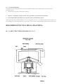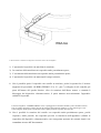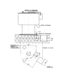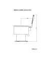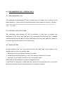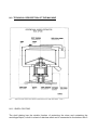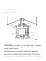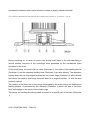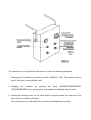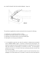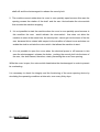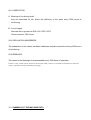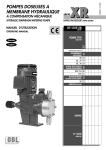
1
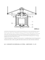
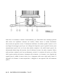
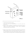
E090401X
02/04/09
ISTRUZIONI D’USO
MANUTENZIONE E
INSTALLAZIONE
INSTALLATION MAINTINANCE
AND USE MANUAL
ZP 400
IMESA S.p.A.
Via degli Olmi 22
31040 Cessalto (TV), Italia
tel. +39.0421.468011
fax +39.0421.468000
www.imesa.it
INDICE GENERALE Pag.
01
RIEPILOGO DATI MARCATURA DELLA MACCHINA
3
02
USO DEL MANUALE DI ISTRUZIONE
4
03
USO PREVISTO – GENERALITA’
4
03.1 Uso previsto
03.2 Caratteristiche generali
03.3 Natura del rischio
4
4
4
DESCRIZIONE TECNICA DELLA MACCHINA
5
04.1 Parti strutturali ed organi – Tav. I
5
04
04.1.1
04.1.2
04.1.3
04.1.4
04.1.5
Fasciame esterno
Fondo fasciame
Basamento
Cestello
Coperchio
04.2 Gruppi
04.2.1
04.2.2
04.2.3
04.2.4
05
06
Trasmissione – Tav.II
Dispositivo richiamo al centro – sospensione – Tav. III
Pannello di comando – Tav. IV
Freno
6
6
6
6
6
7
7
8
9
10
04.3 Rumore
10
INSTALLAZIONE
11
05.1 Disimballaggio e livellamento
05.2 Scarico acqua
05.3 Collegamenti elettrici
11
11
11
PROCEDURA DI AVVIAMENTO
12
06.1 Dare energia
06.2 Controllo senso di rotazione
12
12
12
07
ISTRUZIONI PER L’USO 08
09
07.1 Operazione normale
07.2 Arresto macchina
07.3 Caricamento macchina
13
13
13
DISPOSITIVI DI SICUREZZA: FUNZIONAMENTO E CONTROLLO
14
08.1 Dispositivo di sicurezza apertura coperchio – Tav. VIII
14
MANUTENZIONE
15
09.1 Lubrificazione
09.2 Ammortizzatori
09.3 Cuscinetti
15
15
16
16
10
RIEPILOGO DATI MACCHINA INDICE DELLE TAVOLE
TAVOLA I
TAVOLA II
TAVOLA III
INSIEME GENERALE
TRASMISSIONE
DISPOSITIVO DI RICHIAMO AL CENTRO
TAVOLA IV PANNELLO DI COMANDO 5
7
8
9
17
TAVOLA V DISEGNO FONDAZIONE TAVOLA VI INGOMBRO TAVOLA VII INGOMBRO COPERCHIO APERTO 18
19
14
TAVOLA VIII DISPOSITIVO SICUREZZA APERTURA COPERCHIO ALLEGATO:
SCHEMA ELETTRICO
RIEPILOGO DEI DATI DELLA MARCATURA DELLA MACCHINA •
MARCHIO – LOGO – SOCIETA’:
M.S.L. MECCANICA S.r.l.
Via Forrenera, 2 51019 PONTE BUGGIANESE (PT)
•
IL FABBRICANTE:
• MARCATURA:
M.S.L. Meccanica S.r.l.
MARCHIO
•
MACCHINA:
IDROESTRATTORE CENTRIFUGO
•
MODELLO:
ZP/400
•
MATRICOLA:______________________________
•
RPM: 1450
•
DIAMETRO CESTELLO: 400 mm
•
CAPACITA’ DI CARICO: 8 Kg
•
POTENZA INSTALLATA: 1,1 Kw
•
ANNO DI COSTRUZIONE: ______________
USO DEL MANUALE DI ISTRUZIONE
Il manuale tecnico è indirizzato al personale preposto all’uso, all’installazione, alla manutenzione e alla riparazione guasti.
E’ necessario leggere attentamente i capitoli specifici per poter operare in sicurezza nell’uso,
l’installazione, la manutenzione e le riparazioni dell’idroestrattore.
Il costruttore si riserva il diritto di aggiornamento del manuale senza obbligo di “retrofit”.
Il costruttore si ritiene sollevato da ogni responsabilità nei seguenti casi:
•
•
•
•
•
•
•
Il caricamento della macchina non avvenga nei modi indicati nel manuale;
Non vengono osservate le indicazioni per l’installazione;
Non venga fatta la manutenzione secondo quanto previsto nel manuale;
Vengano elusi o non controllati, con periodicità prevista, i dispositivi di sicurezza che
impediscono la rotazione del cestello con coperchio anche parzialmente aperto;
Vengano effettuate modifiche o interventi non autorizzati;
Vengano centrifugati materiali con densità superiore a quella prevista;
Vengano centrifugate masse superiori a quelle indicate in targhetta.
USO PREVITO – GENERALITA’
03.1 – USO PREVISTO
L’idroestrattore centrifugo mod. ZP/400 è impiegato principalmente per disidratare biancheria, prodotti dell’industria tessile o altri
prodotti, purché la loro massa volumica non superi 1,3 Kg/dmc.
Il carico massimo centrifugabile, al massimo numero di giri: 8 Kg a 1350 rpm.
03.2 – CARATTERISTICHE GENERALI
L’idroestrattore centrifugo mod. ZP/400 è oscillante, in questo tipo di macchina le oscillazioni del cestello dovute alla forza
centrifuga prodotta dal carico sbilanciato vengono ridotte dal dispositivo di richiamo al centro, per effetto delle reazioni di anelli
elastici.
03.3 – NATURA DEL RISCHIO
I rischi connessi all’uso dell’idroestrattore derivano principalmente dalla rotazione della macchina con coperchio anche
parzialmente aperto:
•
azionamento del coperchio con macchina in rotazione;
•
apertura accidentale, anche parziale, del coperchio con macchina in rotazione;
•
azionamento della macchina con coperchio anche parzialmente aperto.
Altri rischi possono derivare dal funzionamento con carico sbilanciato. Un carico eccessivamente sbilanciato può originare una
forza centrifuga sul cestello tale da sollecitare irregolarmente l’albero motore e il dispositivo di richiamo al centro (sospensione).
DESCRIZIONE TECNICA DELLA MACCHINA
04.1 – PARTI STRUTTURALI ED ORGANI – Tav. I
04.1.1 – FASCIAME ESTERNO
Il fasciame esterno assolve il duplice compito di protezione del cestello e di contenimento del liquido centrifugato, è costruito in
lamiera di acciaio inossidabile ed è collegato al basamento con 6 viti M6.
04.1.2 – FONDO FASCIAME
Il fondo fasciame provvede a raccogliere il liquido centrifugato e a convogliarlo all’esterno
mediante un tubo di scarico che si raccorda a un bacino anulare di raccolta sottostante il cestello.
04.1.3 - BASAMENTO
Il basamento, realizzato in robusta fusione di ghisa, porta l’alloggiamento per il dispositivo di richiamo al centro e consente
l’ancoraggio a terra della macchina. Il basamento viene ancorato alla fondazione con tre arpioni di fondazione (tirafondo)
opportunamente calcolati per resistere alle forti sollecitazioni dovute a un funzionamento con carico anche fortemente sbilanciato.
04.1.4 - CESTELLO
I l cestello è composto essenzialmente da due parti: fondo e il mantello.
Il fondo, realizzato in robusta fusione di ghisa ed è interamente rivestito in lamiera di acciaio
inossidabile, porta la sede conica per l’accoppiamento con l’albero motore.
Il mantello è realizzato in lamiera forata di acciaio inossidabile ed è rinforzata da due fasce, una
superiore ed una inferiore. L’unione tra mantello e fondo è realizzata mediante n.8 viti M6 e
relativo dado autobloccante .
04.1.5 – COPERCHIO
La macchina è dotata di un coperchio per impedire che il materiale da centrifugare fuoriesca dall’idroestrattore durante il
funzionamento e nel contempo per evitare che si possa operare nel cestello durante il funzionamento. Il coperchio è incernierato alla
scatola di comando, l’apertura è manuale ed è regolata da un dispositivo di sicurezza.
04.2 - GRUPPI
04.2.1 – TRASMISSIONE – Tav. II
La trasmissione del moto dal motore elettrico al cestello avviene direttamente perché il cestello è calettato direttamente sull’albero
del motore elettrico. Il motore elettrico è appositamente costruito, in esso l’albero (part.1) è supportato da due cuscinetti, uno
superiore radiale rigido a sfere (part.2), e uno inferiore a rulli cilindrici (part.3). Le sedi per l’alloggiamento dei cuscinetti essendo
a tenuta stagna, grazie all’azione degli anelli di tenuta (part.6) per il contenimento del grasso per la lubrificazione che è a vita,
proteggono i cuscinetti da qualunque infiltrazione. Il motore elettrico porta posteriormente una flangia (part.4) per l’ancoraggio
alla flangia del dispositivo di richiamo al centro (part.5).
L’albero di trasmissione, realizzato in acciaio speciale, è sovradimensionato in modo da garantire la
resistenza meccanica, anche con grandi sollecitazioni trasmesse da carichi fortemente sbilanciati.
04.2.2 – DISPOSITIVO DI RICHIAMO AL CENTRO - SOSPENSIONE – Tav. III
Nella fase di avviamento o durante il funzionamento, per effetto della forza centrifuga generata
dalle masse non equilibrate contenute nel cestello, l’albero motore si inclina lateralmente
descrivendo una superficie conica. L’inclinazione dell’albero fa inclinare quindi il motore con la
sua flangia di ancoraggio (part.2) per cui la flangia del dispositivo (part.3) quindi il mozzo porta
ammortizzatori (part.5) che con la sua aletta anulare comprime i due anelli elastici (part.6) che
deformandosi danno luogo alla reazione, forza di richiamo al centro, che tende a riportare l’albero
nella posizione originaria con l’asse perfettamente verticale. La rotazione del mozzo, per effetto
della coppia trasmessa dal motore, soprattutto all’avviamento e in frenatura, viene impedita dai
cagnoli (part.4), solidali al mozzo stesso, che si impegnano nelle tracce degli anelli elastici. Il
dispositivo di richiamo al centro-sospensione è alloggiato in una apposita sede del basamento
(part.1).
04.2.3 - PANNELLO DI COMANDO – Tav. IV
Il pannello di comando è posto a bordo macchina; da esso si possono comandare le seguenti operazioni:
1)
Avviamento della macchina premendo il pulsante “MARCIA”.
La macchina non parte se il coperchio è anche parzialmente aperto.
2)
Arrestare la macchina premendo il pulsante “ARRESTO/EMERGENZA”, con questo comando la macchina termina
immediatamente il ciclo.
3) Impostare il tempo di centrifugazione sul temporizzatore posto all’esterno della scatola di
comando, la scala (0-30min) del temporizzatore è in minuti. Il tempo di centrifugazione
calcolato dall’avviamento all’inizio della frenatura.
4) Impostare il tempo di sblocco del coperchio agendo sul temporizzatore posto all’interno del
pannello di comando (scala 0-60sec). Tale tempo è impostato in fase di collaudo a 30 sec, per
avere un buon margine di sicurezza rispetto al tempo di frenatura e quindi avere la ragionevole
certezza che il cestello è fermo dopo tale tempo. In concomitanza del temporizzatore agisce il
sensore magnetico con il relativo relé di controllo rotazione il quale permette lo sblocco del
coperchio quando l’albero del motore è fermo.
E’ assolutamente vietato impostare il tempo ad un valore inferiore a 30 sec.
Sul pannello di comando ci sono due spie luminose, una bianca ed una rossa, che se illuminate indicano:
•
LAMPADA ROSSA: CESTELLO IN ROTAZIONE – la macchina sta operando.
•
LAMPADA BIANCA: CESTELLO IN ROTAZIONE – la scatola di comando è alimentata.
I dispositivi di comando sono fabbricati in modo da resistere alle sollecitazioni a cui sono sottoposti
durante il funzionamento e all’azionamento.
Gli errori di logica nei comandi non sono possibili perché momento per momento la macchina
accetta solo comandi congrui con la sequenza operativa. Al ripristino di energia elettrica dopo una
interruzione la macchina prosegue il ciclo per il tempo residuo. Trascorso il tempo di
centrifugazione la macchina si arresta e si predispone per un ciclo successivo, come in un ciclo
normale.
04.2.4 - FRENO
La frenatura della macchina avviene direttamente sul motore elettrico con sistema in controcorrente. L’alimentazione del freno è in
corrente continua la quale è derivata dall’autotrasformatore e successivo ponte a diodi raddrizzatori.
04.3 - RUMORE
Per quanto riguarda l’emissione di rumore aereo, il valore della pressione acustica continua equivalente ponderato a quella emessa
da un identico modello di questa macchina in condizioni di normale funzionamento, non supera mai il valore di 60 dB(A).
INSTALLAZIONE
05.1 – DISIMBALLAGGIO E LIVELLAMENTO – Tav. V,VI,VII
Dopo aver tolto l’imballo esterno della macchina procedere alla movimentazione, la macchina è ancorata al pallett di legno per consentire la movimentazione con muletto. La portata del muletto deve essere adeguata al peso della macchina che è circa 100 Kg. Dopo aver trasportato la macchina nel punto di installazione si può eliminare il pallet e posizionare la macchina sulla fondazione precedentemente realizzata in cemento armato, come indicato dal disegno di fondazione, vedi tavola V, con i punti di ancoraggio dei tiranti in corrispondenza dei relativi pozzetti e lo scarico in corrispondenza dello scarico realizzato nella fondazione. Per quanto riguarda gli ingombri della macchina fare riferimento alla tavola VI e VII. Dopo aver verificato la corretta posizione ed eseguito il livellamento dell’idroestrattore si può colare cemento liquido nei pozzetti con i tiranti di fondazione in posizione. Solo dopo un congruo tempo (10 giorni) tale da consentire il totale consolidamento del cemento, si possono bloccare i tiranti. Dopo il bloccaggio definitivo dei tiranti controllare nuovamente il livellamento che può essere riferito al fasciame esterno. Un livellamento non corretto dell’idroestrattore può causare vibrazioni pericolose durante il funzionamento. I tiranti di fondazione con relativi dadi e rondelli sono in dotazione alla macchina; si trovano imballati dentro il cestello. 05.2 – SCARICO ACQUA
Lo scarico dell’acqua dall’idroestrattore può essere collegato, se previsto, al pozzetto di scarico della fondazione con un tubo di
diametro non inferiore al collettore di scarico della macchina.
Se non è predisposto il pozzetto di scarico nella fondazione occorre assicurarsi che il punto di
scarico sia ad un livello più basso del collettore di scarico dell’idroestrattore.
05.3 – COLLEGAMENTI ELETTRICI
I collegamenti elettrici devono essere effettuati unicamente collegando i cavi di alimentazione più la
terra alla morsettiera, alloggiata alla scatola di comando, punti indicati R S T .
La sezione dei cavi deve essere ampiamente dimensionata rispetto alla potenza installata e alla
lunghezza del cavo di alimentazione. Tutti i collegamenti elettrici sono indicati nello schema nello
schema elettrico allegato a questo manuale. Tutti i segnali di servizio sono a bassa tensione di
sicurezza: 24 Volts . La macchina deve essere alimentata con corrente elettrica trifase a 380/400440 volts e frequenza 50-60 hertz. La potenza installata: 1,1 Kw.
Dopo aver effettuato le operazioni di cui ai punti 05.1; 05.2; 05.3 l’installazione è completata.
PROCEDURA DI AVVIAMENTO
Dopo aver effettuato l’installazione dell’idroestrattore come indicato ai punti 05.1; 05.2; 05.3 si devono eseguire operazioni prima
di procedere all’avviamento della macchina.
06.1 – DARE ENERGIA
Dare energia al pannello di comando agendo sull’interruttore generale: ruotare l’interruttore generale nella posizione “T”. 06.2 – CONTROLLO SENSO DI ROTAZIONE
E’ importante controllare il senso di rotazione del cestello, che deve essere quello indicato dalla freccia disegnata sull’adesivo posto
sul coperchio oblò (senso orario).
Nel caso che il senso di rotazione non fosse orario, invertire le fasi elettriche di alimentazione del
motore.
Dopo aver effettuato le operazioni di cui ai punti 06.1; 06.2; 06.3 la macchina è pronta per operare.
ISTRUZIONI PER L’USO
Non sono previsti requisiti particolari per il personale abilitato alla funzione di operatore.
07.1 – OPERAZIONE NORMALE
Il ciclo normale dell’idroestrattore si effettua nel seguente modo:
1) Impostare il tempo di centrifugazione sul temporizzatore posto sulla scatola di comando (vedi
Tav. IV); il tempo di centrifugazione è calcolato dall’avviamento all’inizio frenatura.
2) Aprire il coperchio, caricare la macchina come indicato al punto 07.3, chiudere il coperchio.
3) Premere il pulsante “MARCIA” : la macchina automaticamente inizierà a ruotare, trascorso il
tempo di centrifugazione impostato eseguirà la frenatura, solo quando il cestello sarà
perfettamente fermo sarà possibile aprire il coperchio per scaricare l’idroestrattore ed iniziare un
altro ciclo.
07.2 – ARRESTO MACCHINA
L’idroestrattore può essere fermato in qualunque momento del ciclo operativo attivando il pulsante “ARRESTO/EMERGENZA”
posto sulla scatola di comando (vedi Tav.IV).
Allo stesso modo, qualora si dovessero verificare situazioni pericolose (vibrazioni eccessive, rumori
anomali ecc.) per le quali è necessario fermare la macchina attivare il pulsante
“ARRESTO/EMERGENZA”.
07.3 – CARICAMENTO MACCHINA
Per eliminare i rischi connessi al funzionamento dell’idroestrattore con carico sbilanciato occorre
prestare la massima attenzione nel caricamento del cestello. Il prodotto che deve essere sottoposto a
centrifugazione deve essere distribuito il più uniformemente possibile all’interno del cestello. E’
buona regola sistemare i materiali più pesanti sul fondo.
E’ necessario presenziare la macchina nella fase di avviamento fino al raggiungimento del regime, per controllare il
regolare funzionamento.
DISPOSITIVI
DI
CONTROLLO
SICUREZZA
FUNZIONAMENTO
08.1 – DISPOSITIVO DI SICUREZZA APERTURA COPERCHIO – Tav. VIII
E
L’idroestrattore è dotato di un dispositivo elettromeccanico atto ad impedire:
1) L’apertura del coperchio con macchina in rotazione;
2) La rotazione della macchina con coperchio anche parzialmente aperto;
3) L’avviamento della macchina con coperchio anche parzialmente aperto;
4) L’apertura del coperchio con mancanza di energia elettrica,
1. Non è possibile aprire il coperchio con cestello in rotazione, perché in questa fase il sensore
magnetico di prossimità “ALBERO FERMO” (Tav. II – part.7), collegato al relè controllo giri
posto all’interno del quadro elettrico, rileva la rotazione dell’albero motore e comanda il
bloccaggio del dispositivo elettromeccanico, il quale trattiene meccanicamente l’appendice
solidale al coperchio.
Il sensore magnetico “ALBERO FERMO” rileva il passaggio di un elemento metallico posto sull’albero motore.
Solo se l’albero del motore è fermo (assenza di passaggio dell’elemento metallico), il relè controllo giri eccita
l’elettromagnete del dispositivo elettromeccanico il quale permette l’apertura del coperchio.
2. Non è possibile la rotazione del cestello con coperchio anche parzialmente aperto, perché
l’apertura, anche parziale, del coperchio provoca la fuoriuscita dell’appendice (solidale al
coperchio) dal dispositivo elettromeccanico con conseguente apertura dei contatti elettrici che
comandano arresto dell’idroestrattore.
3. Non è possibile avviare l’idroestrattore con coperchio anche parzialmente aperto, perché in
questa condizione l’appendice solidale al coperchio non consente la chiusura dei contatti
elettrici del dispositivo elettromeccanico con conseguente impossibilità di avviare la macchina.
4. Non è possibile aprire il coperchio con mancanza di energia elettrica, perché in questo caso,
l’elettromagnete del dispositivo elettromeccanico non essendo alimentato trattiene l’appendice
solidale al coperchio impedendone l’apertura.
Se la macchina non deve operare è consigliabile togliere energia.
E’ necessario controllare periodicamente, almeno una volta ogni trenta giorni, l’integrità e il funzionamento del dispositivo apertura
coperchio, simulando le condizioni di intervento.
MANUTENZIONE
09.1 - LUBRIFICAZIONE
•
Cuscinetti dell’albero motore: sono lubrificati a vita; controllare l’efficienza delle tenute ogni
3000 ore di funzionamento.
•
Cerniere del coperchio: lubrificare con grasso.
09.2 - AMMORTIZZATORI
•
E’ prevista la sostituzione degli ammortizzatori di gomma ogni 6000 ore di funzionamento.
09.3 - CUSCINETTI
•
E’ previsto un controllo dei cuscinetti ogni 3000 ore di funzionamento. Per effettuare tale
controllo disinserire il quadro elettrico, aprire il coperchio far ruotare manualmente il cestello;
se si rilevano rumori o vibrazioni anomale verosimilmente i cuscinetti del motore dovranno
essere sostituiti.
RIEPILOGO DATI MACCHINA
Massimo numero di giri (RPM)
1350 (50Hz) – 1620(60Hz) rpm
Carico massimo centrifugabile
8 Kg
Massa volumica massima centrifugabile
1,3 Kg/dmc
Potenza installata
1,1 Kw
Tensione
380/400 V (50Hz) 440 V (60Hz)
Frequenza
50 Hz
Tempo avviamento
25 sec
Tempo frenatura
25 sec
Diametro cestello
400 mm
Altezza cestello
300 mm
Peso complessivo
100 Kg ca.
INDEX
01
– SUMMARY OF THE MACHINE MARKINGS
02
– HOW TO USE THE MAINTENANCE MANUAL
03
– RECOMMENDED USE – GENERAL DATA
03.1 Recommended use
03.2 General specification
03.3 Kinds of risk
04
– TECHNICAL DESCRIPTION OF THE MACHINE
04.1 Structural parts and main components of the machine
04.1.1 Shell plating
04.1.2 Shell bottom
04.1.3 Base
04.1.4 Drum
04.1.5 Cover
04.2 Units
04.2.1 Transmission
04.2.2 Device for resetting the driving shaft while the machine is in motion
04.2.3 Control box
04.2.4 Brake
04.3 Noise
05
– INSTALLATION
05.1 Unpacking and levelling
05.2 Water outlet
05.3 Electrical connections
06
– SWITCHING ON PROCEDURE
06.1 Turning on
06.2 Control of the rotating direction
07
– DIRECTIONS FOR USE
07.1 Normal operation
07.2 Machine stopping
07.3 Machine loading
08
– SECURITY DEVICES: OPERATION AND CONTROL
08.1 Safety device for the cover opening
09
– MAINTENANCE
09.1 Lubrication
09.2 Oscillation absorbers
09.3 Bearings
10
– SUMMARY OF THE MACHINE DATA
DRAWINGS Electrical diagram
01 - SUMMARY OF THE MACHINE
•
BRAND – LOGO – COMPANY:
M.S.L. MECCANICA S.r.l.
Via Forrenera, 2
51019 PONTE BUGGIANESE (PT)
•
MANUFACTURER:
M.S.L. Meccanica S.r.l.
•
EEC MARKING:
MARKING
•
MACHINE:
CENTRIFUGAL HYDRO-EXTRACTOR
•
MODELLO:
ZP/400
•
SERIAL NUMBER: ______________________
•
YEAR OF CONSTRUCTION: ______________
•
RPM:
•
MAXIMUM CENTRIFUGABLE WET LOAD:
•
DRUM DIAMETRE:
•
INSTALLED POWER:
1450
400 mm
1,1 KW
8 Kg
02 – HOW TO USE THE MAINTENANCE MANUAL
This tecnical manual has been issued for the operators in charge of the use, installation,
maintenance and failure repairs.
It is necessary to read the specific sections very carefully, in order to use, install, and carry
out the maintenance and failure repairs of the hydro-extractor under the best safety
conditions.
The manufacturer reserves the right to update the manual without a “retrofit” obligation.
The manufacturer has no responsibility if:
⇒
the loading of the machine is not carried out according to the directions in this
manual;
⇒
the direction for the installation are not followed;
⇒
the maintenance is not carried out according to the directions in this manual;
⇒
the safety devices that prevent the machine from rotating when the cover is
partially or totally opened are not used or checked at the suggested intervals;
⇒
non authorized modifications or operations are carried out;
⇒
materials thicker than recommeded are centrifuged;
⇒
volumes greater than the ones shown on the plate are centrifuged.
03 – RECOMMENDED USE – GENERAL DATA
03.1 RECOMMENDED USE
The centrifugal hydro-extractor ZP 400 is mainly used to dewater linen, products of the
textile industry or other products, provided that their volume does not exceed 1.3 Kg/dm³.
The maximun load which can be dewatered at the maximum number of revolutions is: 8 Kg, wet, at 1450 rev/min
(50Hz) – 1740 (60Hz).
03.2 GENERAL SPECIFICATIONS
The centrifugal hydro-extractor ZP 400 is oscillating. In this type of machine the
oscillations of the drum which are due to the centrifugal force produced by a possible
unbalanced load are reduced by a device that resets the driving shaft while the machine is
in motion, owing to the reaction of the elastic rings.
03.3 KINDS OF RISK
All risks related to the use of the hydro-extractor are mainly due to the rotation of the
machine with its cover even partially open:
⇒ Operating the cover while the machine is in motion
⇒ accidental, even partial opening, of the cover while the machine is in motion
⇒ switching on the machine with the cover even partially open.
Other risks can be caused by use with an unbalanced load.
A load which is excessively unbalanced may cause such a centrifugal force on the drum
that the driving shaft and the resetting device are irregularly stressed.
04 – TECHNICAL DESCRIPTION OF THE MACHINE
04.1
STRUCTURAL PARTS AND MAIN COMPONENTS OF THE MACHINE – Table I
04.1.1 SHELL PLATING
The shell plating has the double function of protecting the drum and containing the
centrifuged liquid, is built in sheet of stainless steel and is connected to the bottom with 6
M6 screws.
04.1.2 SHELL BOTTOM
The shell bottom will collect the centrifuged liquid and convey it towards the outside
through a draining pipe which is connected to an oval receiving tank located undernearth
the drum.
04.1.3 BASE
The base is built in a strong cast iron fusion. It houses the device for resetting the driving
shaft while the machine is in motion and enables you to anchor the machine to the ground.
The base is anchored to the foundation by three anchoring bolts duly calculated to
withstand strong stress due to a highly unbalanced load.
04.1.4 DRUM
The drum is mainly constituted by two parts: the bottom and the shell.
The bottom, made in a strong cast iron fusion and completely coated with a sheet of
stainless steel, houses the conical seat of the coupling with the driving shaft.
The shell is made from a perforated stainless steel sheet and is reinforced by two bands, a
higher band and a lower band. The connection between sheel and bottom is to be riveted
with nr.8 6 mm diametre nails.
04.1.5 COVER
The machine has the cover which, when it is in use, prevents the material to be
centrifuged from escaping from the hydro-extractor and any operation in the drum.
The cover is hinged to the control board, its opening is manual and is regulated by safety
device.
04.2 UNITS
04.2.1 TRANSMISSION – Table II
The transmission of the movement from the electrical motor to the drum occurs directly as the drum is directly coupled to the driving
shaft of the electrical motor.
The electrical motor is built to measure and its driving shaft (Particular 1) is supported by
two bearings: the higher one is a radial rigid ball bearing (Particular 2), the lower one is a
cylindrical roll bearing (Particular 3).
Being leakproof, these housings protect the bearings from any seepage due to the action
of the seal rings (Particular 6) for containing the lubricating grease, which is eternal.
The electrical motor has a collar (Particular 4) on the back to anchor the device for
resetting the driving shaft while the machine is in motion (Particular 5) to the collar itself.
The flexible shaft, made from special steel, is oversized so that it can guarantee
mechanical resistance even under full strain caused by highly unbalanced loads.
04.2.2 DEVICE FOR RESETTING THE DRIVING SHAFT WHILE THE MACHINE IS
IN MOTION – Table III
During switching on ,or when in motion, the driving shaft leans to the side describing a
conical surface, because of the centrifugal force generated by the unbalanced mass
contained in the drum.
As the shaft leans, the motor with its collar (Particular 2), the collar of the resetting device
(Particular 3) and the absorber-holding boss (Particualr 5) are also leaning. The absorberholding boss with its ring-tongue presses the two elastic rings (Particular 6) which buckle
and cause the reaction that brings the shaft back to its original position, i.e. with the axis
perfectly vertical.
The rotation of the boss, due to the couple transmitted by the motor during the starting and
braking phases, is prevented by the elements (Particular 4) which are part of the boss
itself and engage in the traces of the elastic rings.
The device for resetting the driving shaft is housed in a special part of the base (Particular
1).
04.2.3 CONTROL BOX – Table IV
The control box is in the machine itself and can control the following operations:
1. Starting-up the machine by pushing the knob “MARCIA” (ON). The machine will not
start if the cover is even partially open.
2. Stopping
the
machine
by
pushing
the
knob
“ARRESTO/EMERGENZA”
(STOP/EMERGENCY): by pressing this, the machine immediately stops its cycle.
3. Setting the centrifuge time on the timer which is placed outside the control box: the
timer scale is in minutes (0-30min).
The centrifuge time is calculated from the start to the beginning of braking.
4. To set up the time of realese of the cover, acting on the timer that is found within the
control panel. The time is set up to 30 second for having the certainty that the drum is
firm. A magnetic sensor allows the release of the cover when the tree of the motor is
firm.
Prohibited to set up an inferior time to the 30 second.
On the control board there are two warning lights which, if on, indicate the following:
WHITE LAMP: FEDDING - that the electrical box is being fed.
RED LAMP: CENTRIFUGAL ROTATION - that the machine is functioning.
The control devices are made in such a way as to withstand the strain they undergo during
the functioning and when the machine is switched on.
Logical errors in the controls are not possible because moment by moment the machine
only accepts controls which are in congruence with the operation sequence.
When the electric power is restored after an interruption, the machine continues its cycle
for the remaining time. When the centrifugation time is over, the machine stops and gets
ready for a further cycle, as in a normal cycle.
04.2.4 BRAKE
The machine is braked directly on the electrical motor with a countercurrent system. The
brake feeding is in direct current deriving from a transformer located in the control box.
04.3 NOISE
As far as the emission of air noise is concerned, the value of the continuous sound
pressure emitted by the same model of this machine under normal working conditions
never exceeds 60 dB(A).
05 – INSTALLATION 05.1 UNPACKING AND LEVELLING – Table V – VI – VII
After unpacking the machine, put it in place.
The machine is anchored to the wooden palette to enable the fork-lift to move it.
The capacity of the fork-lift should correspond to the machine weight which is 100 Kg.
After transporting the machine to its installation place, the palette can be removed and the
machine can be positioned on the foundation previously prepared in reinforced concrete
as indicated in the foundation drawing (see Table V) with the anchoring points of its
tension bars in correspondence with the relative wells and its drain in correspondence with
the drain built into the foundation.
Regarding the machine dimensions, please refer to Table VI and VII.
After checking that positioning is correct and levelling the hydro-extractor, you can pour
liquid concrete into the wells with the foundation tension bars in position.
After waiting long enough to enable final consolidation of the concrete (ten days), the
tension bars can be blocked.
After finally blocking the tension bars, check the machine levelling again (referring it to the
shell plating).
A non correct levelling of the hydro-extractor may cause dangerous vibration during the
operation.
The foundation tension bars with their relative nuts and washers are supplied with the
machine; they are packed inside the drum.
05.2 WATER OUTLET
The water outlet can be connected, if planned, to the foundation water pit by a tube with a
diametre of at least the same size of the drain collector of the hydro-extractor.
If the water pit is not provided for, make sure that the drain point of the connecting tube is
at a lever than the drain collector of the machine.
05.3 ELECTRICAL CONNECTIONS
The electrical connections must only be carried out by connecting the fedding cables and
the earth cable to the terminal block housed in the control box, at the points indicated with
R S T.
The section of the cables can be over-dimensioned according to the installed power and
the length of the feeding cable.
All electric connections are indicated in the electric diagram enclosed in the present
manual.
All service signals are at safety low voltage: 24 volts.
The machine must be fed with 380/400-440 volts three-phase current and 50-60 Hz.
The installed power is 1,1 KW.
06 – SWITCHING ON PROCEDURE
After finishing the installation of the machine as indicated at points 05.1, 05.2, 05.3, you
have to carry out the following operations before starting the machine.
06.1 TURNING ON
To turn on, operate on the control box by switching the main switch: rotate the main switch
to position “T”.
06.3 CONTROL OF THE ROTATING DIRECTION
It is important to control the rotating direction of the machine.
In order to control the rotating direction, just push the “MARCIA” (START) knob and then
the “ARRESTO” (STOP) knob: once the braking time is over, you can open the cover. The
drum, which is not yet completely still, will enable you to verify the right rotating direction,
which has to be clockwise.
If the rotating direction is not clockwise, reserve the feeding electtric phase of the motor.
After carrying out the operations under Point 06.1, 06.2, the machine is ready for use.
07 – DIRECTIONS FOR USE
No particular qualification is requested for the operators.
07.1 NORMAL OPERATION The normal operating cycle of the machine is carried out as follows:
1. Set the centrifuge time on the timer housed on the control box (see Table IV ); the centrifuge time is calculated from the start to when braking begins 2. Lift the cover, load the machine and close the cover again
3. Push the “MARCIA” knob: the machine will automatically start rotating and once the set
centrifuge time is over it will brake; only when the drum is perfectly still will it be
possible to lift the cover to unload the machine and start another cycle.
07.2 MACHINE STOPPING
-
The machine can be stopped at any moment of the operative cycle by activating the
knob “ARRESTO/EMERGENZA” (STOP/EMERGENCY) placed on the control box (see
Table IV).
-
If sistuation which can be judged dangerous occur (excessive oscillations, vibrations or
abnormal noises), requiring to stop the machine in the shortest possible time, press the
knob “ARRESTO/EMERGENZA” (STOP/EMERGENCY) placed on the control box (see
Table IV ).
07.3 MACHINE LOADING
In order to eliminate the risks connected to the machine functioning with an unbalanced
load, you must be very careful during the loading operation, distributing the material into
the drum as uniformly as possible. It is a good rule to place the heaviest materials on the
bottom.
It is necessary to be present when the machine is working, at least from the switching on
to the steady state, in order to control its regular functioning. If situation which can be
judged dangerous occur (noises, abnormal vibrations) push the stop or emergency knob.
08 – SECURITY DEVICES: OPERATION AND CONTROL
08.1 SAFETY DEVICE FOR THE COVER OPENING – Table VIII
The machine is supplied with an electro-mechanical device to prevent the following:
1) Handling the cover while the machine is rotating
2) Rotation of the machine with the cover even partially open
3) Switching on the machine with the cover even partially open
4) Opening the cover during a power black-out.
1. It is not possible to open the cover when the machine is rotating because prossimity
sensor “ALBERO FERMO” (Table II – Particular 7) deactivates the electromagnet . The
sensor that keeps the shaft still register the passage of a metal placed on the driving
shaft and activates the electromagnet. By releasing its shutter , the electromagnet
pushes the security bolt in the trace of the came preventing, therefore, the shaft and
the cover from rotating.
Only if the driving shaft is still it is possible to open the cover because there are no
passages of the metal element and it is possible to control the sensor that keeps the
shaft still and the electromagnet to release the security bolt.
2. The machine cannot rotate when its cover is even partially open because this case the
opening causes the rotation of the shaft and the cam that activates the micro-switch
that controls the machine stopping.
3. It is not possible to start the machine when its cover is even partially open because in
this condition the cam
would activate the micro-switch
that does not allow the
machine to start; at the same time, the security bolt cannot get into the trace of the the
cam because this is rotated with respect to the condition of closed cover and does not
enable the stud to activate the micro-switch that allows the machine to start.
4. It is not possible to open the cover when the electrical power is off because in this
case the electromagnet releases its shutter , pushing the security bolt into the trace of
the cam ; the shaft cannot, therefore, rotate, preventing the cover from opening.
While the cover is open, the micro switch deactivates the electromagnet in order to prevent
its overheating.
It is necessary to check the integrity and the functioning of the cover opening device by
simulating the operantig conditions at intervals, once every thirty days.
09 – MAINTENANCE
09.1 LUBRICATION
A. Bearings of the driving shaft:
they are lubricated for life; check the efficiency of the seals every 3000 hours of
functioning.
B. Cover hinges:
lubricate with a grease like ROL OIL LITEX / EP2
Check intervals: 1000 hours
09.2 OSCILLATION ABSORBERS
The substitution of the rubber oscillation absorbers should be carried out every 6000 hours
of functioning.
09.3 BEARINGS
The control of the bearings is recommended every 3000 hours of operation.
In order to carry out this control, disconnect the electrical board, lift the cover, manually rotate the drum: if there are
noises or abnormal vibrations, substitute the bearings .
11 – SUMMARY OF THE MACHINE DATA
: 1450(50Hz) – 1740(60Hz) rpm
Maximum number of revolution : 8 Kg
Maximum centrifugable wet load : 1.3 Kg/dm³
Maximum centrifugable mass : 1.1 KW
Installed power : 380/400 V (50Hz) 440 (60Hz)
Tension : 50-60 Hz
Frequency : 25 sec.
Starting‐up time : 25 sec.
Braking time : 400 mm
Drum diametre : 300 mm
Usable drum height : 100 Kg
Total weight