1
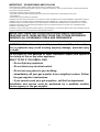
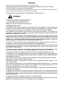
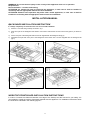
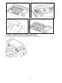
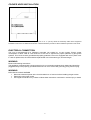
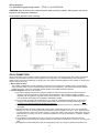
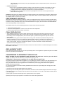
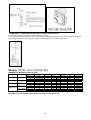
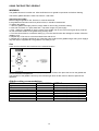
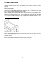
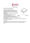
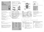
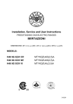
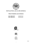
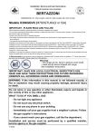
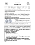
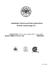
Installation, Service and User Instructions BUILT-IN GAS/ELECTRIC COOKTOP BERTAZZONI DIMENSIONS: 48’’(1216 mm) (W) x 25 1/8’’ (640mm) (D) MODELs: CTYK..(U or A)7X(2,5)A 310682 IMPORTANT - PLEASE READ AND FOLLOW -Before beginning installation, please read these instructions completely and carefully. -Do not remove permanently affixed labels, warnings, or plates from the product. This may void the warranty. -Please observe all local and national codes and ordinances. -Please ensure that this product is properly grounded. -The installer should leave these instructions with the consumer who should retain for local inspector's use and for future reference. -The electrical plug should always be accessible. Installation must conform with local codes or in the absence of codes, the National Fuel Gas Code ANSIZ223.1-latest edition. Electrical installation must be in accordance with the National Electrical Code, ANIS/NFPA70 - latest edition and/or local codes. IN CANADA: Installation must be in accordance with the current CAN/CGA-B149.1 National Gas Installation Code or CAN/CGA-B 149.2, Propane Installation Code and/or local codes. Electrical installation must be in accordance with the current CSA C22.1 Canadian Electrical Codes Part 1 and/or local codes. Installation of any gas-fired equipment should be made by a licensed plumber. A manual gas shut-off valve must be installed in the gas supply line ahead of the oven in the gas flow for safety and ease of service. IMPORTANT: SAVE FOR LOCAL ELECTRICAL INSPECTOR’S USE. READ AND SAVE THESE INSTRUCTIONS FOR FUTURE REFERENCE. OBSERVE ALL GOVERNING CODES AND ORDINANCES. WARNING: If the information in this manual is not followed exactly, a fire or explosion may result causing property damage, personal injury or death. Do not store or use gasoline or other flammable vapors and liquids in the vicinity of this or any other appliance. WHAT TO DO IF YOU SMELL GAS - Do not light any appliance. - Do not touch any electrical switch. - Do not use any phone in your building. - Immediately call your gas supplier from a neighbor’s phone. Follow the gas supplier’s instructions. - If you cannot reach your gas suppliers, call the fire department. Installation and service must be performed by a qualified installer, service agency or the gas supplier. 2 WARNING Read this instruction booklet before installing and using the appliance. The manufacturer will not be responsible for any damage to property or to persons caused by incorrect installation or improper use of the appliance. The manufacturer reserves the right to make changes to its products when considered necessary and useful, without affecting the essential safety and operating characteristics. This appliance has been designed for non-professional, domestic use only. Warning: do not use this appliance to heat a room. Installation instructions This appliance shall only be installed by an authorized person. This appliance shall be installed in accordance with the manufacturer’s installation instructions, IMPORTANT: this appliance must be installed in accordance with the norms & standards of the country where it will be installed. The installation of this appliance must conform to local codes and ordinances. In the absence of local codes, Installations must conforms to American National Standards, National Fuel Gas Code ANSI Z223.1 – latest edition** or B149.1. If local codes permit, a flexible metal appliance connection with the new AGA or CGA certified design, max. 5 feet (1,5 m) long, ½” I.D. is recommended for connecting this appliance to the gas supply line. Do not bend or damage the flexible connector when moving the appliance. The pressure regulator has ½” female pipe thread. The appropriate fitting must be determined based on the size of your gas supply line, the flexible metal connector and the shutoff valve. The appliance, when installed, must be electrically grounded in accordance with local codes or, in the absence of local codes, with the National Electrical Code, ANSI/NFPA 70. The appliance must be isolated from the gas supply piping system by closing its individual manual shutoff valve during any pressure testing of the gas supply piping system at test pressures equal to or less than ½ psi (3.5 kPa). For use with a pressure regulator. The regulator supplied must be used with this appliance; it shall be properly installed in order to be accessible when appliance is installed in its final location. The gas appliance pressure regulator must be set for the gas with which the appliance is used. This appliance can be used with Natural Gas and LP Gas. It is shipped from the factory adjusted for use with Natural Gas: CONVERSION FIXED ORIFICES ARE LOCATED IN THE LITERATURE PACK SUPPLIED WITH THE UNIT. A gas nozzle kit for the change of type of gas are contained inside the package together with the gas appliance installation kit and instruction booklet. The maximum inlet gas supply pressure incoming to the gas appliance pressure regulator is 20’’ water column (5 kPa) . The minimum gas supply pressure for checking the regulator setting shall be at least 1“ w.c. (249 Pa) above the inlet specified manifold pressure to the appliance (this operating pressure is 4” w.c. (1.00 kPa) for Natural Gas and 11” w.c. (2.75 kPa for LP Gas). All opening and holes in the wall and floor, back and under the appliance shall be sealed before installation of the appliance. To eliminate the risk of burns or fire by reaching over heated surface units, cabinet storage space located above the surface units should be avoided. If cabinet storage is to be provided, the risk can be reduced by installing a rabge hood that projects horizontally a minimum of 5 inches beyond the bottom of the cabinets It’s always compulsory to install the riser even for an island installation ATTENTION: A manual valve shall be installed in an accessible location in the gas line external to the appliance for the purpose of turning on or shutting off gas to the appliance 3 WARNING: Do not use aerosol sprays in the vicinity of this appliance while it is in operation Requirements Room ventilation – Location and venting. ATTENTION: An exhaust fan may be used with the appliance; in each case it shall be installed in conformity with the appropriate national and local standards. ATTENTION: Exhaust hood operation may affect other vented appliances; in each case it shall be installed in conformity with the appropriate national and local standards. INSTALLATION MANUAL BACKGUARD INSTALLATION INSTRUCTION It’s always compulsory to install the riser even for an island installation 1) Remove n°2 screws fixing worktop as shown in fig.1 2) Place front part of the backguard and attach it from bottom side with the two removed screws (point 2) as shown in fig .2 3) Fix the front part of the backguard with the screws supplied with the backguard kit (fig.3) 4) Assemble back part with front part of the backguard and fix them with a screws supplied with the backguard kit (fig.4) 1 2 3 4 WORKTOP FRONTGUARD INSTALLATION INSTRUCTIONS In order to increase the clearance between front edge of the worktop and the burners for your safety it is recomended to install the worktop frontguard supplied with the appliance. For installation instructions follow the instructions indicated in the following figures 4 ELECTRIC GRIDDLE INSTALLATION INSTRUCTIONS For installation the electric griddle, see the instructions indicated in the figure 5 INSTALLATION SIDE-BY-SIDE TO KITCHEN CABINET 1. This range may be installed directly adjacent to existing 36" (91.5 cm) high cabinets. IMPORTANT: The top border of the worktop should be at the same level of the adjacent cabinet countertop. This can be accomplished by raising the unit using the adjustment spindles on the legs. 2. The range CANNOT be installed directly adjacent to sidewalls, tall cabinets, tall appliances, or other vertical surfaces above 36" (91.4 cm) high. There must be a minimum of 6" (15.2 cm) side clearance. 3. Within the side clearance to combustible vertical surfaces above 36" (91.5 cm) , the maximum wall cabinet depth must be 13" (33.0 cm) and wall cabinets within this side clearance must be 18" (45.7 cm) above countertop level and countertop hightness shall be from 35”1/2(90,2 cm) to 37” ¼ (94,6 cm). A B C D E F G H i L 6 6”(15.2cm) MIN 36”(91.5cm) 48” (122 cm) 13”(33.0cm)MAX 18”(45.7cm)MIN 36”(91.5cm) 6”1/2(16.5cm) 1”(2.5cm) MIN 9/16” (1.8cm) 2”( 5 cm) MIN COOKER HOOD INSTALLATION The bottom of the hood should be 25 ½ " (65 cm) min. to 31 ½ " (80 cm) above the countertop. Refer to the rangehood installation instructions for additional information. These dimensions provide for safe and efficient operation of the hood. ELECTRICAL CONNECTION This unit is manufactured for a polarized, grounded 120 volt/60 Hz, 16 amp system. Electric power consumption is about 1080 W. The minimum of 102 VAC is required for proper operation of gas ignition systems. This circuit must be grounded and properly polarized. The unit is equipped witth a SJT power cord. In case of replacement, the cable shall be replaced with one of the same type, size and length. WARNING Electrical Grounding Instructions This appliance is equipped with a three-prong plug for your protection against shock hazard and should be plugged directly into a properly grounded socket. Do not cut or remove the grounding prong from this plug. WARNING ELECTRICAL SHOCK HAZARD Disconnect electrical power at the circuit breaker box or fuse box before installing the gas cooker Electrically ground gas cooker Use copper conductors only. Failure to follow these instructions could resul in serious injury or death 7 Wiring diagram For freestanding gas range model CTYK..(U or A)7X(2,5)A CAUTION: label all wires prior to disconnection when servicing controls. Wiring errors can cause improper and dangerous operation. Verify proper operation after servicing. GAS CONNECTION All gas connections must be made according to national and local codes. TheThis gas supply (service) line must be the same size or greater than the inlet line of the appliance. This range uses a 1/2" NPTinlet (see fig. in this chapter for details of gas connections installations).On all pipe joints use sealant resistantinstallations) inlet. Sealant on ali pipe joints must be resistive to LP gas. 1. Manual Shut-off Valve: This installer-supplied valve must be installed in the gas service line ahead of the appliance in the gas flowstream and in a position where it can be reached quickly in the event of an emergency. The manual shut-off valve shall be installed properly in order to be accessible whenthe appliance is installed in definitive position 2. Pressure Regulator (see fig. in this chapter) a) All cooking equipment must have a pressure regulator on the incoming service line for safe and efficient operation, since service pressure may fluctuate with local demand. The pressure regulator is supplied separately with the appliance; regulator has two female threads ½” NPT; it shall be installed properly in order to be accessible when appliance is installed in finaldefinitive position. b) Any conversion required must be performed by your dealer or a qualified licensed plumber or gas service company. Please provide the service person with this manual before work is started on the range. (Gas conversions are the responsibility of the dealer or end user.) c) This range can be used with Natural or LP/Propane gas. It is shipped from the factory adjusted for use with natural gas. d) Manifold pressure should be checked with a manometer, natural gas requires 4.0" W.c.P. and LP/Propane requires 11.0" W.C.P. Incoming line pressure upstream from the regulator must be 1" W.c.P. higher than the manifold pressure in order to check the regulator. The regulator used on this range can withstand a maximum input pressure of 1/2 PSI (14.0" W.c.P.) If the line pressure is in excess of that amount, a stepdown regulator will be required. e) The appliance, its individuai shut-off valve, and pressure regulator must be disconnected from the gas supply piping system during any pressure testing of that system at pressures in excess of 1/2 psig (3.45 kPa). f) The appliance must be isolated from the gas supply piping system by closing its individuai manual shut-off 8 valve during any pressure testing of the gas supply piping system at test pressures equal to or less than 1/2 psig (3.45 kPa). 3. Flexible Connections: a) If the unit is to be installed with flexible couplings and/or quick disconnect fittings, the installer must use a heavy-duty, AGA design-certified commerciai flexible connector of at least 1/2" (1.3 cm) ID NPT (with suitable strain reliefs) in compliance with ANSI Z21.41 and Z21.69 standards. b) In Canada: CAN 1-6.10-88 metal connectors for gas appliances and CAN 1-6.9 M79 quick disconnect device for use with gas fuel. CAUTlON: Leak testing of the appliance shall be conducted according to the manufacturer's instructions. Before placing the oven into operation, always check for leaks with a soapy water solution or other acceptable method. DO NOT USE AN OPEN FLAME TO CHECK FOR LEAKS! PERFORMANCE CHECKLlST All burners are tested before leaving the factory. There are no adjustments for the burners if connected according to the information on the rating plate. Check each burner for proper operations. Flames should be blue in all settings. If service is required, contact your dealer for the name of their authorized servi ce agency. Gas conversions and initial installation are not the responsibility of the manufacturer. The installer should carry out the following performance checks. Refer to instructions below. 1. Check surface burner ignition. 2. Check low flame adjustment – surface burner valve center stem adjustment. 3. Check for gas leaks (odors) at ali gas connections. FINAL PREPARATION 1. Some stainless steel parts may have a plastic protective wrap which must be removed. The interior of the oven should be washed thoroughly with hot. soapy water to remove film residues and any installation dust or debris before being used for food preparation, then rinsed and wiped dry. Solutions stronger than soap and water are rarely needed. 2. Ali stainless steel body parts should be wiped with hot, soapy water and with a liquid deaner designed for this materia!. If buildup occurs, do not use steel wool. abrasive cloths, cleaners, or powders! If it is necessary to scrape stainless steel to remove encrusted materials, soak with hot, wet cloths to loosen the material, then use a wood or nylon scraper. Do not use a metal knife, spatula, or any other metal tool to scrape stainless steel! Scratches are almost impossible to remove. NOTE: These installation instructions should remain with the unit for future reference. The electrical diagram is located in the backside or the ccoker REPLACEMENT PARTS Only authorized replacement parts may be used in performing service on the appliance. Replacement parts are available from factory authorized parts distributors. CONVERSIONE TO DIFFERENT TYPES OF GAS Before carrying out any maintenance work, disconnect the appliance from the gas and electric supply. For Natural Gas fit regulator assembly described in Fig. Adaptation of the pressure regulator for use with different type of gas The pressure regulator supplied with the appliance is a convertible type pressure regulator for use with Natural Gas at a nominal outlet pressure of 4” w.c. or LP gas at a nominal outlet pressure of 11” w.c. and it is pre-arranged from the factory to operate with one of these gas/pressure as indicated in the pre-arranging labels affixed on the appliance, package and Instruction booklet. To convert the regulator for use with the other gas different from which one it is pre-arranged it is enough perform the following operations: 1) Unscrew by hand the upper metal stopper of the regulator. 2) Unscrew by hand the white plastic piece screwed under the above mentioned metal stopper, afterward screw it again in opposite way under the metal stopper (for gas reference see the written “LP” and “NAT” with relative indicating arrows on the white piece). 3) Screw again by hand the metal stopper in the original position on the regulator. Operating in this way the gas regulator is converted for use with the other gas/pressure. 9 - CHANGING THE NOZZLES FOR USE WITH OTHER TYPES OF GAS: To change the nozzles of the burners use the following procedure: Lift up the burners and unscrew the nozzles ( Fig.) using an adjustable spanner of 7 mm and change the nozzles with those designed for the new gas supply according to the information given in TABLE shown below. Models CTYK..(U or A)7X(2, 5)A Adapting to different types of gas Burner Position Auxiliary Front R Semi-Rapid Rear L & C Front C Rear R Rapid Front L Inner Dual Burner Front L Outer Injector diam. [mm.] 0,92 0,56 1,17 0,73 1,55 0,98 0,80 0,50 N°2 x 1,30 N°2 x 0,83 Gas Type NG LP (Propane) NG LP (Propane) NG LP (Propane) NG LP (Propane) NG LP (Propane) Pressure [i.w.c.] 4” 11” 4” 11” 4” 11” 4” 11” 4” 11” Max Rate [BTU/h] [W] 3750 1098 3750 1098 6000 1759 6300 1845 10400 2046 11400 3339 2730 799 2900 8479 15000 4394 16400 4804 CAUTION: save the orifices removed from the appliance for future use 10 Min Rate [BTU/h] [W] 900 264 900 264 1500 439 1500 439 2500 732 2500 732 900 264 900 264 4500 1319 4500 1319 By-pass diam. [mm] Regulated 0,29 Regulated 0,36 Regulated 0,47 Regulated 0,29 Regulated 0,65 REGULATION OF BURNERS Work surface burner adjustment: follow the instructions below to adjust the work surface burner minimum: 1) Light the burner and set the knob to the MINIMUM position (small flame). 2) Remove the knob of the valve that is press fit on the rod of that valve. 3) The cooker is equipped with safety valves, use a small slotted screwdriver the choke valve located on the valve body and turn the choke screw to the right or left until the burner flame is adjusted to minimum 4) Make sure that the flame does not go out when switching quickly from the MAXIMUM to the MINIMUM position. WARNING: The above-mentioned adjustment should be made only for natural gas, while for operation with liquid gas the screw must be locked at the end in a clockwise direction. The broiler burner always operates at maximum and therefore no minimum adjustment is required. SERVICE & MAINTENANCE INSTRUCTIONS Service and maintenance only to be carried out by an authorised person To replace parts such as burners, valves and electric components, the appliance must be open removing the worktop. Note: if the valves must be replaced, first disassemble the ignitions switches wires. It is recommended to replace the valve gaskets each time the valve is replaced, thus ensuring a perfect seal between the body and the gas train. WARNING: After first installation of the appliance or after any service intervention concerning main gas parts of the appliance, make the leak test using water with soap on the gas connections in order to verify the correct installation. Do not use fire for gas leak testing. USER MANUAL IMPORTANT INSTRUCTION WARNINGS: Proper installation. Be sure your appliance is properly installed and grounded by a qualified technician Never Use Your Appliance for Warming or heating the Room. Do Not Leave Children Alone – Children should not be left alone or unattended in area where appliance is in use. They should never be allowed to sit or stand on any part of the appliance. Wear Proper Apparel –Loose fitting or hanging garments should never be worn while using the appliance User Servicing - Do not repair or replace any part of the applilance unless specifically recommended in the manual. All other servicing should be referred to a qualified technician. Do Not Use Water in Grease Fires- Smother fire or flame or use dry chemical or foam-type extinguisher. Use Only Dry Potholders Moist or damp potholderrs on hot surface may result in burns from steam. Do not let potholder touch hot heating elements. Do not use a towel or other bulky cloth. Never Leave Surface Units Unattended at High Heat Setting – Boilover causes smoking and greasy spillovers that may ignite Make Sure Reflector Pans or Drip Bowls Are in Place – Absence of these pans or bowls during cooking may subject wiring or components undernearth to damage. Utensil Handles Should Be Turned Inward and Not Extend Over Adjacent Surface Units – To reduce the risk of burns, ignition of flammable materials, and spillage due to unintentional contact with the utensil, the handle of a utensil should be positioned so that it is turned inward, and does not extend over adjacent surface units. 11 Do not to cover the burners of cooktop with aluminium paper Keeping appliance area clear and free from combustible materials, gasoline and other flammable vapors and liquid. Do not store dangerous or flammable material in the cabinet areas above appliance; store them in a safe place in order to avoid potential hazards. For safe use of appliance, do not use it for space heating. Do not use aerosol sprays in the vicinity of this appliance while it is in operation DESCRIPTIONS DESCRIPTIVE CAPTION FOR HOB DESCRIPTION OF HOBS 1. Small Burner 2. Medium burner 3. Rapid burner 4. Dual burner 5. Griddle Model CTYK..U7X(2, 5)A fig. A fig.A CONTROL PANEL DESCRIPTION On the control panel, small symbols show the function of each knob or key. Here as follows are the several controls that a cooker can have: shows the disposition of burners on the worktop, the full dot identifies the burner in the symbol object (in this case the front burner on the right). the symbol shows the disposition of burners and the griddle on the worktop, the full dot identifies the element in object (in this case the electric griddle). 12 USING BURNERS A diagram is etched on the control panel above each knob which indicates which burner corresponds to that knob. (flame) Manual ignition: Manual ignition is always possible even when the power is cut off or in the event of prolonged power failure. Turn the knob that corresponds to the burner selected counterclockwise to the MAXIMUM position at the etched star (large flame) and place a lit match up to the burner. Automatic electric ignition: Turn the knob that corresponds to the burner selected anticlockwise direction to the MAXIMUM position at the etched star (large flame) and then press the knob down to activate the spark ignition. Once ignited, keep pressing the knob for about 10 seconds to allow the flame to heat the thermocouple. If the burner does not remain alight after releasing the knob repeat the above procedure, Note: It is recommended not to try to ignite the burner if the relative flame cap is not in the correct position Note: Dual burner is composed by two burner (inside and outside); each one operates under the relative gas valve indipendently from the other one. Instructions for the ignition of the dual wok burner: turn on the central burner first, then turn on the external ring. Tips for using burners correctly: WARNING: During use of each gas burner(s) adjust the burner flame size properly so it does not extend beyond the edge of the cooking utensil. This is an instruction based on safety considerations - Use suitable pots for each burner (see Fig. and Table ) - When the liquid is boiling, turn down the knob to the MINIMUM position. - Always use pots with a cover. Correct flame aspect: verify that aspect flame of the worktop burners be completely blue and with an aspect as indicated in figure(flame) Table Burner Recommended pan diameters inches (mm) Small Medium Large Dual burner 3½”-51/2”(90 – 140) 51/2”- 101/4”(140 – 260) 71/8”- 101/4” (180 – 260) 82/3”-101/4” (220 – 260) WARNING: check the position of the burner caps before operation. Correct usage of pans: - Dry the bottom of the pan before placing it on the hotplate. - Use pots with a flat, thick bottom, except for wok cooking. - When using the burners, ensure that the handles of the pans are correctly positioned. Keep children away from the appliance. - When cooking foods with oil and fat, which are very flammable, the user should not leave the appliance unattended. WOK PAN: To use the wok pan, please utilize a suitable wok adaptor grid; wok pan external diameter shall not be less than 10” (25cm) and not more than 16”(40cm). WARNING: If the power is cut off, the burners can be lit with matches. The burners equipped with a safety thermocouple can only be lit when the knob is in the MAXIMUM position (large flame etching). 13 USING THE ELECTRIC GRIDDLE WARNING The griddle element is hot after use. Allow sufficient time for griddle components cool before cleaning. The electric griddle element is rated 120 volts AC 1100 watts. Seasoning the griddle Before using the griddle for the first time, it must be seasoned. If the griddle has not been used for a period of time, it should be reseasoned. To season the gridlle: 1. clean the griddle thoroughly with hot, soapy water to remove any protective coating. 2. rinse with a mixture of 1 quart water and 1 cup white vinegar. Dry thoroughly. 3. Pour 1 teaspoon vegetable oil into the center of the griddle. Do not use corn oil as it gets sticky. Rub the oil over the entire surface of the griddle using a heavy cloth. 4. Turn the control knob to a maximum setting (7). Turn the heat off when the oil begins to smoke. Allow the griddle to cool. 5. Repeat step 3. Be sure to cover the entiresurface with the oil 6. Repeat step 4. Allow the griddle to cool. Wipe the entire surface of the griddle using a heavy cloth. Apply a very thin layer of vegetable oil. The griddle is now ready to use. Use Press and turn the knob anti-clockwise to the selected position Pre-heat at the maximum temperature, ( 7 position) for 15 minutes, then place the food on the griddle and cook to the desired temperature. The activation of the griddle is shown by the indicator light which is also found on the front panel of the appliance. Griddle cooking recommendations FOOD KNOB POSITION SETTING Eggs Bacon; Breakfast Sausage Toasted Sandwiches Boneless Chicken Breasts Boneless Pork Chops, ½” thick Ham Slices, ½” thick Pancakes; French Toast Potatoes; Hash Browns 5-6 6 5-6 6 6 6 6 7 300°F to 325°F 350°F to 375°F 325°F to 350°F 350°F to 375°F 350°F to 375°F 350°F to 375°F 350°F to 375°F 375°F to 400°F 14 (150°C to 160°C) (177°C to 190°C) (160°C to 177°C) (177°C to 190°C) (177°C to 190°C) (177°C to 190°C) (177°C to 190°C) (190°C to 205°C) CLEANING THE APPLIANCE: Never use abrasive cleaners Before cleaning the appliance it should be disconnected from the power supply. Cleaning the work surface: periodically clean the burner heads, the cast iron pan supports and the burner caps using warm water. Any spillage must always be removed as soon as possible using a rag. If it become difficult to open or close a valve, do not force it, but immediately request the assistance of the technical service personnel. Cleaning the enamelled parts: Enamelled parts should be cleaned frequently with soapy water. Never use abrasive powder. Do not leave acidi or alkaline substances on the enamelled parts (such as vinegar, lemon juice, salt, tomato sauce, etc.) and do not wash the enamelled parts while they are still hot. Cleaning the griddle: Thoroughly clean the griddle of grease and food particles, using a square-edged spatula, while it is still hot. Remove drip tray and discard grease into a grease resistant container for disposal. Wash drip tray with hot soapy water, rinse and dry. Wipe the griddle with a dry, heavy, coarse cloth to remove any remaining residue and food particles. Wash with hot soapy water, rinse and dry . Once the griddle has cooled, rub the surface lightly with vesetable oil. Do not use corn oil or cooking sprays as they get sticky. If the gridlle is cleaned with anything other than a dry, heavy, coarse cloth, it will need to be reseasoned. Never flood the hot griddle with cold water. This could cause the griddle to crack or warp. Cleaning the stainless steel parts: Clean the parts with soapy water and dry them with a soft cloth. The shine is maintained by periodically using specific stainless steel cream cleaner. Never use abrasive powders. Use specific stainless steel cream cleaner to eliminate the glue remains afther the elimination of the blue plastic protection film on the worktop after installation. Cleaning the burner caps: Lift the burner caps from the burner heads and wash them in soapy water and dry thoroughly. Before replacement on the burner head ensure that the holes are not clogged. ATTENTION: for further details about cleaning of the appliance, please contact your applliance retailer. 15 AFTER SALE SERVICE: Please note here below details for after save service. Refer to warranty certificate for warranty condiftions Dealer /Importer: Name, address, phone SERVICE CENTERS Name Phone MANUFACTURER: BERTAZZONI SPA VIA PALAZZINA, 8 – 42016 – GUASTALLA (REGGIO E.) ITALY Tel. +39 0522/226411 – telefax +39 0522/226440 – http://www.bertazzoni-italia.com 16