1
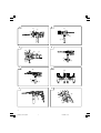
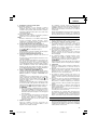
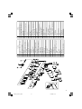
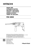
Impact Drill
Trapano a percussione
L220114
Read through carefully and understand these instructions before use.
Prima dell’uso leggere attentamente e comprendere queste istruzioni.
Handling instructions
Istruzioni per l’uso
001Cover_L220114_WE
1
12/24/08, 16:35
1
5
2
6
6
4
5
4
3
8
3
4
B
@
9
8
4
A
5
3
6
C
5
4
D
E
F
3
7
8
K
H
G
I
J
9
1
00Table_L220114_WE
1
12/24/08, 16:35
9
English
Italiano
1
Drill chuck
Mandrino trapano
2
Chuck wrench
Chiave mandrino
3
Tighten
Stringere
4
Loosen
Allentare
5
Sleeve
Collare
6
Ring
Anello
7
Lock collar
Collare di blocco
8
Side handle
Maniglia laterale
9
Switch trigger
Grilletto interruttore
0
Push button
Pulsante
A
R mark
L mark
B
Segno R
C
D
Depth gauge
Segno L
Calibro di profondità
Change lever
Leva di cambiamento
E
Impact
Impatto
F
Rotation
Rotazione
G
H
Gear shift dial
Speed control dial
Regolazione di velocità
Comando di velocità
I
High speed
Alta velocità
J
K
Low speed
Bassa velocità
Stopper
Fermo
2
00Table_L220114_WE
2
12/24/08, 16:35
Symbols
WARNING
The following show
symbols used for the
machine. Be sure that
you understand their
meaning before use.
Read all safety
warnings and all
instructions.
Failure to follow the
warnings and
instructions may result
in electric shock, fire
and/or serious injury.
Only for EU countries
Do not dispose of electric tools
together with household waste
material!
In observance of European
Directive 2002/96/EC on waste
electrical and electronic
equipment and its
implementation in accordance
with national law, electric tools
that have reached the end of
their life must be collected
separately and returned to an
environmentally compatible
recycling facility.
Simboli
AVVERTENZA
Di seguito mostriamo i
simboli usati per la
macchina. Assicurarsi di
comprenderne il
significato prima dell’uso.
Leggere tutti gli
avvertimenti di
sicurezza e tutte le
istruzioni.
La mancata osservanza
degli avvertimenti e delle
istruzioni potrebbe essere
causa di scosse elettriche,
incendi e/o gravi lesioni.
Solo per Paesi UE
Non gettare le
apparecchiature elettriche tra i
rifiuti domestici.
Secondo la Direttiva Europea
2002/96/CE sui rifiuti di
apparecchiature elettriche ed
elettroniche e la sua
attuazione in conformità alle
norme nazionali, le
apparecchiature elettriche
esauste devono essere
raccolte separatamente, al fine
di essere reimpiegate in modo
eco-compatibile.
3
00Table_L220114_WE
3
12/24/08, 16:35
English
GENERAL POWER TOOL SAFETY WARNINGS
WARNING
Read all safety warnings and all instructions.
Failure to follow the warnings and instructions may result in
electric shock, fire and/or serious injury.
Save all warnings and instructions for future reference.
The term “power tool” in the warnings refers to your mainsoperated (corded) power tool or battery-operated (cordless)
power tool.
1) Work area safety
a) Keep work area clean and well lit.
Cluttered or dark areas invite accidents.
b) Do not operate power tools in explosive atmospheres,
such as in the presence of flammable liquids, gases
or dust.
Power tools create sparks which may ignite the dust
or fumes.
c) Keep children and bystanders away while operating
a power tool.
Distractions can cause you to lose control.
2) Electrical safety
a) Power tool plugs must match the outlet.
Never modify the plug in any way.
Do not use any adapter plugs with earthed (grounded)
power tools.
Unmodified plugs and matching outlets will reduce
risk of electric shock.
b) Avoid body contact with earthed or grounded surfaces,
such as pipes, radiators, ranges and refrigerators.
There is an increased risk of electric shock if your
body is earthed or grounded.
c) Do not expose power tools to rain or wet conditions.
Water entering a power tool will increase the risk of
electric shock.
d) Do not abuse the cord. Never use the cord for carrying,
pulling or unplugging the power tool.
Keep cord away from heat, oil, sharp edges or moving
parts.
Damaged or entangled cords increase the risk of
electric shock.
e) When operating a power tool outdoors, use an
extension cord suitable for outdoor use.
Use of a cord suitable for outdoor use reduces the
risk of electric shock.
f) If operating a power tool in a damp location is
unavoidable, use a residual current device (RCD)
protected supply.
Use of an RCD reduces the risk of electric shock.
3) Personal safety
a) Stay alert, watch what you are doing and use common
sense when operating a power tool.
Do not use a power tool while you are tired or under
the influence of drugs, alcohol or medication.
A moment of inattention while operating power tools
may result in serious personal injury.
b) Use personal protective equipment. Always wear eye
protection.
Protective equipment such as dust mask, non-skid
safety shoes, hard hat, or hearing protection used for
appropriate conditions will reduce personal injuries.
c) Prevent unintentional starting. Ensure the switch is
in the off-position before connecting to power source
and/or battery pack, picking up or carrying the tool.
01Eng_L220114_WE
4
d)
e)
f)
g)
Carrying power tools with your finger on the switch
or energising power tools that have the switch on
invites accidents.
Remove any adjusting key or wrench before turning
the power tool on.
A wrench or a key left attached to a rotating part of
the power tool may result in personal injury.
Do not overreach. Keep proper footing and balance
at all times.
This enables better control of the power tool in
unexpected situations.
Dress properly. Do not wear loose clothing or
jewellery. Keep your hair, clothing and gloves away
from moving parts.
Loose clothes, jewellery or long hair can be caught
in moving parts.
If devices are provided for the connection of dust
extraction and collection facilities, ensure these are
connected and properly used.
Use of dust collection can reduce dust related hazards.
4) Power tool use and care
a) Do not force the power tool. Use the correct power
tool for your application.
The correct power tool will do the job better and safer
at the rate for which it was designed.
b) Do not use the power tool if the switch does not
turn it on and off.
Any power tool that cannot be controlled with the
switch is dangerous and must be repaired.
c) Disconnect the plug from the power source and/or
the battery pack from the power tool before making
any adjustments, changing accessories, or storing
power tools.
Such preventive safety measures reduce the risk of
starting the power tool accidentally.
d) Store idle power tools out of the reach of children
and do not allow persons unfamiliar with the power
tool or these instructions to operate the power tool.
Power tools are dangerous in the hands of untrained
users.
e) Maintain power tools. Check for misalignment or
binding of moving parts, breakage of parts and any
other condition that may affect the power tool's
operation.
If damaged, have the power tool repaired before use.
Many accidents are caused by poorly maintained
power tools.
f) Keep cutting tools sharp and clean.
Properly maintained cutting tools with sharp cutting
edges are less likely to bind and are easier to control.
g) Use the power tool, accessories and tool bits etc. in
accordance with these instructions, taking into
account the working conditions and the work to be
performed.
Use of the power tool for operations different from
those intended could result in a hazardous situation.
5) Service
a) Have your power tool serviced by a qualified repair
person using only identical replacement parts.
This will ensure that the safety of the power tool is
maintained.
PRECAUTION
Keep children and infirm persons away.
When not in use, tools should be stored out of reach of children and
infirm persons.
4
12/24/08, 16:35
English
3. Before drilling into walls, ceilings or floors, ensure
that there are no concealed power cables inside.
4. Always use side handle and hold the tool firmly with
both hands.
5. Always use the impact drill with clockwise rotation,
when using it as an impact drill. (Fig. 9)
IMPACT DRILL SAFETY WARNINGS
1. Wear ear protectors with impact drills.
Exposure to noise can cause hearing loss.
2. Use auxiliary handles supplied with the tool.
Loss of control can cause personal injury.
SPECIFICATIONS
Voltage
Power input
Speed change
230V
790 W
1
0 – 1000 min-1
0 – 600 min-1
13 mm
20 mm
40 mm
8000 min-1
Forward rotation
No load speed
Reverse rotation
Steel
Capacity
Concrete
Wood
Full load impact rate
Weight (without cord)
2
0 – 3000 min-1
0 – 1800 min-1
8 mm
13 mm
25 mm
26000 min-1
2.2 kg
STANDARD ACCESSORIES
(1) Plastic Case ................................................................ 1
(2) Side Handle ................................................................ 1
(3) Depth Gauge .............................................................. 1
Standard accessories are subject to change without
notice.
APPLICATIONS
䡬 By combined actions of ROTATION and IMPACT:
Boring holes in hard materials (concrete, marble,
granite, tiles, etc.)
䡬 By ROTATIONAL action:
Boring holes in metal, wood and plastic.
PRIOR TO OPERATION
1. Power source
Ensure that the power source to be utilized conforms
to the power requirements specified on the product
nameplate.
2. Power switch
Ensure that the power switch is in the OFF position. If
the plug is connected to a receptacle while the power
switch is in the ON position, the power tool will start
operating immediately, inviting serious accident.
3. Extension cord
When the work area is removed from the power
source, use an extension cord of sufficient thickness
and rated capacity. The extension cord should be
kept as short as practicable.
4. Selecting the appropriate drill bit
䡬 When boring concrete or stone
Use the drill bits specified in the Optional Accessories.
䡬 When boring metal or plastic
Use an ordinary metalworking drill bit.
䡬 When boring wood
Use an ordinary woodworking drill bit.
However, when drilling 6.5 mm or smaller holes, use
a metalworking drill bit.
5. Mounting and dismounting of the bit.
(1) Mounting the bit
Turn the sleeve counterclockwise and open the chuck.
After inserting the drill bit into the chuck as far it will
go, grip the ring and close the chuck by turning the
sleeve clockwise as viewed from the front. (Fig. 1)
(2) Dismounting the bit
Grip the ring and open the chuck by turning the
sleeve counterclockwise. (Fig. 1)
NOTE
When the sleeve does not become loose any further,
fix the side handle to ring, hold side handle firmly,
then turn the sleeve to loosen by hand. (Fig. 2)
6. Check the rotational direction (Fig. 3)
The bit rotates clockwise (viewed from the rear side)
by pushing the R-side of the push button.
The L-side of the push button is pushed to turn the bit
counterclockwise.
(The L and R marks are provided on the body.)
CAUTION
Always use the impact drill with clockwise rotation,
when using it as an impact drill.
7. Fixing the side handle (Fig. 4)
Attach the side handle to the mounting part.
Rotate the side handle grip in a clockwise direction
to secure it.
Set the side handle to a position that is suited to the
operation and then securely tighten the side handle
grip.
To attach a depth gauge on the side handle, insert
the gauge into the U-shaped groove on the side
handle, adjust the position of the depth gauge in
accordance with the desired depth of the hole, and
firmly tighten the side handle grip. (Fig. 5)
5
01Eng_L220114_WE
5
12/24/08, 16:35
English
8. IMPACT to ROTATION changeover (Fig. 6)
Shift the change lever between the right and left
positions to switch easily between IMPACT (rotation
and impact) and ROTATION (rotation only),
respectively.
To bore holes in hard materials such as concrete,
stone and tiles, shift the change lever to the rightmark).
hand position (as indicated by the
The drill bit operates by the combined actions of
impact and rotation.
To bore holes in metal, wood and plastic, shift the
change lever to the left-hand position (as indicated
mark). The drill bit operates by rotational
by the
action only, as in the case of a conventional electric
drill.
CAUTION
䡬 Do not use the Impact Drill in the IMPACT function
if the material can be bored by rotation only.
Such action will not only reduce drill efficiency,
but may also damage the drill tip.
䡬 Operating the Impact Drill with the change lever
in mid-position may result in damage. When
switching, make sure that you shift the change
lever to the correct position.
9. High-speed/Low-speed changeover:
Prior to changing speed, ensure that the switch is in
the OFF position, and the drill has come to a complete
stop.
To change speed, rotate the gear shift dial as indicated
by the arrow in Fig. 7. The numeral “1” engraved on
the drill body denotes low speed, the numeral “2”
denotes high speed.
If it is hard to turn the gear shift dial, turn the chuck
slightly in either direction and then turn the gear shift
dial again.
HOW TO USE
1. Switch operation
䡬 When the trigger is depressed, the tool rotates. When
the trigger is released, the tool stops.
䡬 The rotational speed of the drill can be controlled by
varying the amount that the trigger switch is pulled.
Speed is low when the trigger switch is pulled slightly
and increases as the trigger switch is pulled more.
䡬 The desired rotation speed can be pre-selected with
the speed control dial.
Turn the speed control dial clockwise for higher speed
and counterclockwise for lower speed. (Fig. 8)
䡬 Pulling the trigger and pushing the stopper, it keeps
the switched-on condition which is convenient for
continuous running. When switching off, the stopper
can be disconnected by pulling the trigger again.
CAUTION
If the L-side of push button is pressed for reverse bit
rotation, the stopper cannot be used.
2. Drilling
䡬 When drilling, start the drill slowly, and gradually
increasing speed as you drill.
䡬 Always apply pressure in a straight line with the bit.
Use enough pressure to keep drilling, but do not
push hard enough to stall the motor or deflect the bit.
䡬 To minimize stalling or breaking through the material,
reduce pressure on drill and ease the bit through the
last part of the hole.
䡬 If the drill stalls, release the trigger immediately,
remove the bit from the work and start again. Do not
click the trigger on and off in an attempt to start a
stalled drill. This can damage the drill.
䡬 The larger the drill bit diameter, the larger the reactive
force on your arm.
Be careful not to lose control of the drill because of
this reactive force.
To maintain firm control, establish a good foothold,
use side handle, hold the drill tightly with both hands,
and ensure that the drill is vertical to the material
being drilled.
MAINTENANCE AND INSPECTION
1. Inspecting the drill bits
Since use of an abraded drill bits will cause motor
malfunctioning and degraded efficiency, replace the
drill bits with a new one or resharpening without
delay when abrasion is noted.
2. Inspecting the mounting screws
Regularly inspect all mounting screws and ensure
that they are properly tightened. Should any of the
screws be loose, retighten them immediately. Failure
to do so could result in serious hazard.
3. Maintenance of the motor
The motor unit winding is the very “heart” of the
power tool. Exercise due care to ensure the winding
does not become damaged and/or wet with oil or
water.
4. Inspecting the carbon brushes
For your continued safety and electrical shock
protection, carbon brush inspection and replacement
on this tool should ONLY be performed by an
Authorized Service Center.
5. Replacing supply cord
If the supply cord of Tool is damaged, the Tool must
be returned to Authorized Service Center for the cord
to be replaced.
6. Service parts list
CAUTION:
Repair, modification and inspection of Power Tools
must be carried out by an Authorized Service Center.
This Parts List will be helpful if presented with the
tool to the Authorized Service Center when requesting
repair or other maintenance.
In the operation and maintenance of power tools, the
safety regulations and standards prescribed in each
country must be observed.
MODIFICATION:
Power Tools are constantly being improved and
modified to incorporate the latest technological
advancements.
Accordingly, some parts may be changed without
prior notice.
GUARANTEE
We guarantee DATACOL Power Tools in accordance
with statutory/country specific regulation. This guarantee
does not cover defects or damage due to misuse, abuse,
or normal wear and tear. In case of complaint, please
send the Power Tool, undismantled, with the
GUARANTEE CERTIFICATE found at the end of this
Handling instruction, to an Authorized Service Center.
6
01Eng_L220114_WE
6
12/24/08, 16:35
English
NOTE
Due to DATACOL’s continuing program of research and
development, the specifications herein are subject to
change without prior notice.
IMPORTANT
Correct connection of the plug
The wires of the mains lead are coloured in accordance
with the following code:
Blue:- Neutral
Brown:- Live
As the colours of the wires in the mains lead of this tool
may not correspond with the coloured markings
identifying the terminals in your plug proceed as follows:
The wire coloured blue must be connected to the terminal
marked with the letter N or coloured black.
The wire coloured brown must be connected to the
terminal marked with the letter L or coloured red.
Neither core must be connected to the earth terminal.
NOTE
This requirement is provided according to BRITISH
STANDARD 2769: 1984.
Therefore, the letter code and colour code may not be
applicable to other markets except United Kingdom.
Information concerning airborne noise and vibration
The measured values were determined according to
EN60745 and declared in accordance with ISO 4871.
Measured A-weighted sound power level: 109 dB (A)
Measured A-weighted sound pressure level: 98 dB (A)
Uncertainty KpA: 3 dB (A).
Wear ear protection.
The typical weighted root mean square acceleration
value: 12.9 m/s2.
7
01Eng_L220114_WE
7
12/24/08, 16:35
Italiano
AVVERTIMENTI GENERALI DI SICUREZZA SUGLI
UTENSILI ELETTRICI
AVVERTENZA
Leggere tutti gli avvertimenti di sicurezza e tutte le istruzioni.
La mancata osservanza degli avvertimenti e delle istruzioni
potrebbe essere causa di scosse elettriche, incendi e/o gravi
lesioni.
Salvare tutti gli avvertimenti e le istruzioni per riferimenti
futuri.
Il termine “elettroutensili” riportato nelle avvertenze si riferisce
agli elettroutensili azionati con alimentazione di rete (via cavi) o
a batterie (senza cavi).
1) Sicurezza dell’area operativa
a) Mantenere l'area operativa pulita e ordinata.
Aree operative sporche o disordinate possono favorire
gli infortuni.
b) Non utilizzare gli elettroutensili in atmosfere esplosive,
ad es. in presenza di liquidi, gas o polveri infiammabili.
Gli elettroutensili generano delle scintille che
potrebbero accendere la polvere o i fumi.
c) Tenere lontani bambini e astanti durante l'utilizzo degli
elettroutensili.
Qualsiasi distrazione può essere causa di perdita di
controllo.
2) Sicurezza elettrica
a) Le spine degli elettroutensili devono essere idonee alle
prese disponibili.
Non modificare mai le prese.
Con gli elettroutensili a massa (messi a terra), non
utilizzare alcun adattatore.
L'utilizzo di spine intatte e corrispondenti alle prese
disponibili ridurrà il rischio di scosse elettriche.
b) Evitare qualsiasi contatto con le superfici a massa o a
terra, quali tubi, radiatori, fornelli e frigoriferi.
In caso di messa a terra o massa del corpo, sussiste
un maggior rischio di scosse elettriche.
c) Non esporre gli elettroutensili alla pioggia o all'umidità.
La penetrazione di acqua negli elettroutensili
aumenterà il rischio di scosse elettriche.
d) Non tirare il cavo. Non utilizzarlo per il trasporto, o per
tirare o scollegare l'elettroutensile.
Tenere il cavo lontano da fonti di calore, oli, bordi
appuntiti o parti in movimento.
Cavi danneggiati o attorcigliati possono aumentare il
rischio di scosse elettriche.
e) Durante l'uso degli elettroutensili all'esterno, utilizzare
una prolunga idonea per usi esterni.
L'utilizzo di cavi per esterno riduce il rischio di scosse
elettriche.
f) Se è impossibile evitare l’impiego di un utensile elettrico
in un luogo umido, utilizzare l’alimentazione protetta
da un dispositivo a corrente residua (RCD).
L’uso di un RCD riduce il rischio di scosse elettriche.
3) Sicurezza personale
a) Durante l'uso degli elettroutensili, state all'erta,
verificate ciò che state eseguendo e adottate sempre il
buon senso.
Non utilizzate gli elettroutensili qualora siate stanchi,
sotto l'influenza di farmaci, alcol o cure mediche.
Anche un attimo di disattenzione durante l'uso degli
elettroutensili potrebbe essere causa di gravi lesioni
personali.
02Ita_L220114_WE
8
b) Indossate l'attrezzatura di protezione personale.
Indossate sempre le protezioni oculari.
L'attrezzatura protettiva, quali maschera facciale,
calzature antiscivolo, caschi o protezioni oculari ridurrà
il rischio di lesioni personali.
c) Impedite le accensioni involontarie. Prima del
collegamento a una sorgente di alimentazione e/o
pacco batteria e prima di raccogliere o trasportare
l’utensile, verificate che l'interruttore sia posizionato
su OFF.
Il trasporto degli elettroutensili tenendo le dita
sull'interruttore o l’attivazione elettrica degli utensile
che hanno l’interruttore su ON, implica il rischio di
incidenti.
d) Prima di attivare l'elettroutensile, rimuovete qualsiasi
chiave di regolazione.
Lasciando la chiave in un componente in rotazione
dell'elettroutensile, sussiste il rischio di lesioni
personali.
e) Mantenersi in equilibrio. Mantenersi sempre su due
piedi, in equilibrio stabile.
Ciò consente di controllare al meglio l'elettroutensile
in caso di situazioni impreviste.
f) Vestirsi in modo adeguato. Non indossare abiti larghi
o gioielli. Tenere i capelli, gli abiti e i guanti lontano
dalle parti in movimento.
Abiti allentati, gioielli e capelli lunghi potrebbero
impigliarsi nelle parti in movimento.
g) In caso di dispositivi provvisti di collegamento ad
apparecchiature di rimozione e raccolta polveri,
verificare che queste siano collegate e utilizzate in
modo adeguato.
L'utilizzo della raccolta della polvere può ridurre i
rischi connessi alle polveri.
4) Utilizzo e manutenzione degli elettroutensili
a) Non utilizzare elettroutensili non idonei. Utilizzare
l'elettroutensile idoneo alla propria applicazione.
Utilizzando l'elettroutensile corretto, si garantirà
un'esecuzione migliore e più sicura del lavoro, alla
velocità di progetto.
b) Non utilizzare l'elettroutensile qualora non sia possibile
accenderlo/spegnerlo tramite l'interruttore.
É pericoloso utilizzare elettroutensili che non possano
essere azionati dall'interruttore. Provvedere alla relativa
riparazione.
c) Prima di effettuare qualsiasi regolazione, sostituire gli
accessori o depositare gli elettroutensili, scollegare la
spina dalla presa elettrica e/o il pacco batteria
dall’utensile elettrico.
Queste misure di sicurezza preventive riducono il
rischio di avvio involontario dell'elettroutensile.
d) Depositare gli elettroutensili non utilizzati lontano dalla
portata dei bambini ed evitare che persone non esperte
di elettroutensili o non a conoscenza di quanto riportato
sulle presenti istruzioni azionino l'elettroutensile.
É pericoloso consentire che utenti non esperti utilizzino
gli elettroutensili.
e) Manutenzione degli elettroutensili. Verificare che non
vi siano componenti in movimento disallineati o
bloccati, componenti rotti o altre condizioni che
potrebbero
influenzare
negativamente
il
funzionamento dell'elettroutensile.
In caso di guasti, provvedere alla riparazione
dell'elettroutensile prima di riutilizzarlo.
Molti incidenti sono causati da una scarsa
manutenzione.
8
12/24/08, 16:36
Italiano
f)
Mantenere gli strumenti di taglio affilati e puliti.
Gli strumenti di taglio in condizioni di manutenzione
adeguata, con bordi affilati, sono meno soggetti al
bloccaggio e sono più facilmente controllabili.
g) Utilizzare l'elettroutensile, gli accessori, le barrette, ecc.
in conformità a quanto riportato nelle presenti istruzioni,
tenendo in debita considerazione le condizioni operative
e il tipo di lavoro da eseguire.
L’uso dell’utensile elettrico per operazioni diverse da
quelle previste potrebbe causare una situazione
pericolosa.
AVVERTIMENTI DI SICUREZZA PER IL
TRAPANO A PERCUSSIONE
1. Indossare protezioni per le orecchie con le sonde a
percussione.
L’esposizione al rumore può causare la perdita
dell’udito.
2. Utilizzare le leve ausiliarie fornite con l’utensile.
La perdita di controllo può causare lesioni alla
persona.
3. Prima di praticare fori nei muri, soffitti o pavimenti,
assicurarsi che non ci siano, nacostiall’interno, cavi
elettrici.
4. Utilizzae sempre la manopola laterale e afferrare
saldamente lo strumento con entrambe le mani.
5. Usando il trapano nel modo a impatto, inserire sempre
la direzione di rotazione in senso orario. (Fig. 9)
5) Assistenza
a) Affidate le riparazioni dell'elettroutensile a persone
qualificate che utilizzino solamente parti di ricambio
identiche.
Ciò garantirà il mantenimento della sicurezza
dell'elettroutensile.
PRECAUZIONI
Tenere lontano dalla portata di bambini e invalidi.
Quando non utilizzati, gli strumenti dovranno essere deposti
lontano dalla portata di bambini e invalidi.
CARATTERISTICHE
Voltagio
Potenza assorbita
Cambio di velocità
230V
790 W
Rotazione in avanti
Velocità senza cario
Rotazione indietro
Acciao
Capacitá mandrino
Cemento
Legno
Frequenza d’impatto a pieno carico
Peso (senza il cavo)
1
0 – 1000 min-1
0 – 600 min-1
13 mm
20 mm
40 mm
8000 min-1
ACCESSORI STANDARD
(1) Custodia di plastica ................................................... 1
(2) Impugnatura laterale ................................................. 1
(3) Calibro di profondità ................................................. 1
Gli accessori standard possono essere cambiamn to
senza preavviso.
IMPIEGHI
䡬 Azione combinata di ROTAZIONE e BATTITO:
Per l’esecuzione di fori in superfici dure (cemento,
marmo, granito, ecc.).
䡬 Funzionamento solo a ROTAZIONE:
Per l’esecuzione di fori nel metallo, legno e plastica.
PRIMA DELL’USO
1. Alimentazione
Assicurarsi che la rete di alimentazione che si vuole
usare sia compatibile con le caratteristiche relative
all’alimentazione di corrente specificate nella piastrina
dell’apparecchio.
2
0 – 3000 min-1
0 – 1800 min-1
8 mm
13 mm
25 mm
26000 min-1
2,2 kg
2. Interruttore di dorrente
Mettere l’interruttore in posizione OFF. Se la spina è
infilata in una presa mentre l’interruttore è accesso,
l’utinsile elettrico si mette immediatamente in moto,
facilitando il verificarsi di incidenti gravi.
3. Prolunga del cavo
Quando l’ambiente di lavoro è lontano da una presa
di corrente, usare una prolunga del cavo di sufficiente
spessore e di prestazione adeguata. La prolunga deve
essere piú corta possibile.
4. Scelta della punta appropriata
䡬 Quando si fora cemento o pietra
Usare la punta indicata engli accessori disponibili a
richiesta.
䡬 Quando si fora metallo o plastica
Usare una punta normale de metallo.
䡬 Quando si fora il legno
Usare una punta normale da legno. Tuttavia, quando
si fanno fori da 6,5 mm o inferiori, usare una punta
da metallo.
9
02Ita_L220114_WE
9
12/24/08, 16:36
Italiano
5. Installazione e rimozione delle punte.
(1) Montaggio della punta
Girare il manicotto in senso antiorario e aprire il
mandrino. Dopo aver inserito la punta trapano nel
mandrino il più possibile, afferrare l’anello e chiudere
il mandrino girando il manicotto in senso orario visto
dal davanti. (Fig. 1)
(2) Smontaggio della punta
Afferrare l’anello e chiudere il mandrino girando il
manicotto in senso antiorario. (Fig. 1)
NOTA
Quando il manicotto non si allenta ulteriormente,
fissare la maniglia laterale all’anello, tenere
saldamente la maniglia laterale e quindi girare il
manicotto per allentarlo a mano (Fig. 2).
6. Controllo della direzione di rotazione (Fig. 3)
Il trapano ruota in senso orario (visto dal retro) quando
si preme il lato R del pulsante. Premere il lato L del
pulsante per far girare il trapano in senso antiorario.
(I segni L e R sono marcati sul corpo.)
ATTENZIONE
Usando il trapano nel modo a impatto, inserire sempre
la direzione di rotazione in senso orario.
7. Fissaggio dell’impugnatura laterale (Fig. 4)
Attaccare l’impugnatura laterale alla sezione di
montaggio.
Ruotare il gancio dell’impugnatura laterale in senso
orario per fissarla.
Regolare l’impugnatura laterale in una posizione che
sia comoda per l’operazione e quindi stringerne
fermamente il gancio. Per fissare un calibro di
profondità all'impugnatura laterale, infilare il calibro
nella scanalatura a forma di U sull'impugnatura
laterale, regolare la posizione del calibro secondo la
profondità desiderata per il foro e serrare saldamente
la presa dell'impugnatura laterale. (Fig. 5)
8. Cambio da IMPATTO a ROTAZIONE (Fig. 6)
Spostare la leva del cambio tra le posizioni destra e
sinistra per alternare facilmente rispettivamente tra
IMPACT (rotazione e impatto) e ROTATION (solo
rotazione).
Per trapanare fori in materiali duri come cemento,
pietra e piastrelle, spostare la leva del cambio alla
). La
posizione destra (come indicato dal segno
punta del trapano agisce con una combinazione di
impatto e rotazione.
Per trapanare fori in metallo, legno e plastica, spostare
la leva del cambio sulla posizione di sinistra (come
indicato dal segno ). La punta del trapano agisce solo
in rotazione, come per un trapano elettrico normale.
ATTENZIONE
䡬 Non usare il trapano variabile battente e avvitatore
nella posizione IMPACT se il materiale puó essere
forato dalla sola rotazione. Un tale fatto non solo
diminuirá l’efficacia del trapano ma danneggerá
anche la punta.
䡬 Se si usa il trapano a percussione con la leva del
cambio in posizione intermedia ne possono
risultare danni. Quando si cambia posizione,
assicurarsi di spostare la leva del cambio sulla
posizione corretta.
9. Cambio di velocità:
Prima di cambiare velocità, assicurarsi che
l’interruttore sia spento (posizione OFF) e che il
trapano si sia arrestato del tutto.
Per cambiare velocità, ruotare la manòpola di
regolazione della velocità come indicato dalla freccia
nella Fig. 7. Il numero “1” inciso sul corpo del trapano
indica la velocità bassa ed il numero “2” indica la
velocità alta.
Qualora risulti difficile ruotare la regolazione di velocità,
ruotare leggermente il mandrino in entrambe le
direzioni, quindi ruotare ancora la regolazione di velocità.
MODO DI IMPIEGO
1. Uso dell’interruttore
䡬 Quando il grilletto è premuto, l’utensile ruota. Quando
il grilletto viene rilasciato, l’utensile si ferma.
䡬 La velocità di rotazione del trapano può essere
controllata variando la pressione esercitata sul
grilletto. La velocità è bassa quando il grilletto
interruttore è premuto leggermente e aumenta
quando si preme maggiormente.
䡬 La velocità di rotazione desiderata può essere
impostata con il comando di velocità.
Girare il comando di velocità in senso orario per
velocità maggiori o in senso antiorario per velocità
inferiori. (Fig. 8)
䡬 Se si preme il grilletto e si spinge il fermo, si può
mantenere la condizione attivata, comodo per il
funzionamento continuo. Per spegnere, il fermo può
essere sbloccata premendo di nuovo il grilletto.
ATTENZIONE
Premendo il lato sinistro del pulsante per avviare la
rotazione indietro, il fermo non potrà essere utilizzato.
2. Trapanatura
䡬 Quando si trapana, avviare il trapano lentamente e
aumentare gradualmente la velocità mentre si
procede.
䡬 Applicare sempre pressione in linea retta con la punta.
Usare una pressione sufficiente a continuare la
trapanatura ma non spingere con forza tale da
bloccare il motore o deviare la punta.
䡬 Per ridurre il minimo l’arresto del motore o il
trapassamento del materiale, ridurre la pressione sul
trapano e lasciare entrare la punta nella parte finale
del foro.
䡬 Se il trapano si blocca, rilasciare immediatamente il
grilletto, estrarre la punta dal lavoro e ricominciare.
Non premere e rilasciare il grilletto per riavviare il
trapano bloccato. Questo potrebbe danneggiare il
trapano.
䡬 Quando più grande è il diametro della punta del
trapano, tanto maggiore sarà la forza esercitata sul
braccio dell’operatore.
Fare attenzione a non perdere controllo del trapano a
causa di questa forza di reazione.
Per mantenere un controllo saldo, piazzare bene i
piedi, usare la maniglia laterale, tenere saldamente il
trapano con entrambe le mani e assicurarsi che il
trapano sia verticale rispetto al materiale da trapanare.
MANUTENZIONE E CONTROLLI
1. Ispezione delle punte trapano
Poiché l’uso di punte trapano usurate causa problemi
di funzionamento del motore e una minore efficienza,
sostituire le punte trapano con altre nuove o riaffilarle
subito quando si nota usura.
10
02Ita_L220114_WE
10
12/24/08, 16:36
Italiano
2. Controllo delle punte perforanti e dei maschi
Poiché l’uso continuativo di una punta perforante o
di um maschio logorati può diminuire la capacità di
funzionamento e provocare eventuali sovracarichi al
motore, sostituire o affilare la punta perforante od il
maschio, senza indugio, quando si nota una eccessiva
usura.
3. Manutenzione del motore
L’avvolgimento del motore è il vero e proprio “cuore”
dell’utensili elettrici. Fare attenzione a non
danneggiare l’avvolgimento e/o a non bagnarlo con
olio o acqua.
4. Ispezione delle spazzole di carbone
Per Per mantenere la vostra sicurezza e la protezione
da scosse elettriche, l’ispezione delle spazzole di
carbone e la loro sostituzione su questo utensile
deve essere eseguita SOLO da un centro assistenza
autorizzato.
5. Sostituzione del cavo di alimentazione
Se il cavo di alimentazione dell’attrezzo è danneggiato,
l’attrezzo deve essere rinviato ad un centro assistenza
autorizzato per la sostituzione del cavo.
6. Lista dei pezzi di ricambio
CAUTELA:
Riparazioni, modifiche e ispezioni di utensili elettrici
devono essere eseguite da un centro assistenza
autorizzato.
Questa lista dei pezzi torna utile se viene presentata
con l’utensile al centro assistenza autorizzato quando
si richiedono riparazioni o altri interventi di
manutenzione.
Nell’uso e nella manutenzione degli utensili elettrici
devono essere osservate le normative di sicurezza e i
criteri prescritti in ciascun paese.
MODIFICHE:
Gli utensili elettrici vengono continuamente migliorati
e modificati per includere le più recenti innovazioni
tecnologiche.
Di conseguenza, alcuni pezzi possono essere
modificati senza preavviso.
Informazioni riguardanti i rumori trasmessi dall’aria e le
vibrazioni
I valori misurati sono stati determinati in conformitá a
EN60745 e descritti in conformità alla normativa ISO 4871.
Livello misurato di potenza sonora pesato A: 109 dB (A)
Livello misurato di pressione sonora pesato A: 98 dB (A)
KpA incertezza: 3 dB (A)
Indossare protezioni per le orecchie.
Il valore efficace pesato tipico dell’accelerazione è di
12,9 m/s2.
GARANZIA
Garantiamo gli Utensili Elettrici DATACOL in conformità
alle specifiche normative imposte dalla legge e dai paesi.
Questa garanzia non copre difetti o danni dovuti a uso
erroneo, abuso o normale usura. In caso di lamentele, si
prega di inviare l’Utensile Elettrico, non smontato,
insieme al CERTIFICATO DI GARANZIA che si trova al
termine di queste Istruzioni per l’uso, ad un Centro di
Assistenza Autorizzato.
NOTA
A causa del continuo programma di ricerca e sviluppo
della DATACOL, le caratteristiche riportate in questo
foglio sono soggette a cambiamenti senza preventiva
comunicazione.
11
02Ita_L220114_WE
11
12/24/08, 16:36
12
03Back_L220114_WE
12
12/24/08, 16:36
PIN D5
LABEL (FOR SLIP CLUTCH)
30
SHIFT ARM
27
GEAR SET
RETAINING RING (E-TYPE) FOR D15
SHAFT
26
28
GEAR COVER (A) ASS’Y
25
29
SPRING (H)
STEEL BALL D3.5
23
24
SHIFT PIN
O-RING (S-22)
21
22
SHIFT LEVER ASS’Y
SHIFT LEVER
19
20
CHANGE SHAFT
INNER COVER
17
18
CHANGE LEVER
CHANGE COVER
15
16
WASHER (B)
SECOND PINION AND GEAR SET
13
14
RATCHET (B)
TAPPING SCREW (W/FLANGE)
11
12
SPRING (A)
STEEL BALL D6.35
9
BALL BEARING 6202DDCMPS2
RATCHET (A)
7
8
10
RETAINING RING FOR D35 HOLE
DUST SEAL
5
6
DRILL CHUCK 13VLRE-N
SPINDLE
3
4
1
Part Name
FLAT HD. SCREW (A) (LEFT HAND)
M6×25
Item
No.
ARMATURE
503 DEPTH GAUGE
502 SIDE HANDLE
501 CASE
CORD
RUBBER BUSHING
56
CORD ARMOR
CORD CLIP
TAPPING SCREW (W/FLANGE) D4×16
CHOKE COIL (BLUE)
INTERNAL WIRE (BLUE) 55L
EARTH TERMINAL
NOISE SUPPRESSOR
LABEL
BRUSH HOLDER
CARBON BRUSH
CHOKE COIL (BROWN)
INTERNAL WIRE (BROWN) 100L
SWITCH
PUSHING BUTTON
HANDLE COVER
TAPPING SCREW (W/FLANGE) D4×20
NAME PLATE
HOUSING
BALL BEARING 608VVC2PS2L
STATOR
HE×. HD. TAPPING SCREW D4×50
FAN GUIDE
57
55
54
53
52
51
50
49
48
47
46
45
44
43
42
41
40
39
38
37
36
35
34
33
BALL BEARING 608DDC2PS2L
RETAINING RING FOR D22 HOLE
31
Part Name
32
Item
No.
13
03Back_L220114_WE
13
12/24/08, 16:36
English
Italiano
CERTIFICATO DI GARANZIA
GUARANTEE CERTIFICATE
Model No.
Serial No.
Date of Purchase
Customer Name and Address
Dealer Name and Address
(Please stamp dealer name and address)
1
2
3
4
5
Modello
N° di serie
Data di acquisto
Nome e indirizzo dell'acquirente
Nome e indirizzo del rivenditore
(Si prega di apporre il timbro con questi
dati)
✄
1
2
3
4
5
14
03Back_L220114_WE
14
12/24/08, 16:36
1
2
3
4
✄
5
15
03Back_L220114_WE
15
12/24/08, 16:36
16
03Back_L220114_WE
16
12/24/08, 16:36
17
03Back_L220114_WE
17
12/24/08, 16:36
18
03Back_L220114_WE
18
12/24/08, 16:36
Italiano
English
EC DECLARATION OF CONFORMITY
We declare under our sole responsibility that this
product is in conformity with standards or standardized
documents EN60745, EN55014 and EN61000 in
accordance with Council Directives 2004/108/EC and
98/37/EC.
This declaration is applicable to the product affixed CE
marking.
DICHIARAZIONE DI CONFORMITÀ CE
Si dichiara sotto nostra responsabilità che questo
prodotto è conforme agli standard o ai documenti
standardizzati EN60745, EN55014 e EN61000 conforme
alle direttive 2004/108/CE e 98/37/CE del concilio.
Questa dichiarazione è applicabile ai prodotti cui sono
applicati i marchi CE.
Representative office in Europe
Hitachi Fercad Power Tools Italia S.p.A.
Via Retrone 49-36077, Altavilla Vicentina (VI), Italy
30.1. 2009
Declared by
Hitachi Koki Co., Ltd.
Shinagawa Intercity Tower A, 15-1, Konan 2-chome,
Minato-ku, Tokyo, Japan
K. Kato
Board Director
Datacol S.r.L.
Strada Statale 11, Z.A.I.
37047 San Bonifacio (VR), Italy
901
Code No. C99144142 E
Printed in Ireland
03Back_L220114_WE
19
12/24/08, 16:36