1
DDX
P RO A U D I O P OW E R A M P L I F I E R
PROTECT
models
PRO AUDIO POWER AMPLIFIER
CLIP/LIM
-10dB
EXP
-20dB
HI-TEMP
SIGNAL
ACTIVE
-5
-1
0dB
-80
POWER
-5
-16
-3 -20
-40
1522
-12 -10 -7
-12 -10 -7
-16
-20
DDX
-3
-1
0dB
-40
-80
Ch A
Ch B
TEOTON PATENTED TECHNOLOGY
PROTECT
PRO AUDIO POWER AMPLIFIER
CLIP/LIM
-10dB
EXP
-20dB
HI-TEMP
SIGNAL
-12 -10 -7
ACTIVE
-1
0dB
-80
POWER
-5
-16
-3 -20
-40
2022
-12 -10 -7
-5
-16
-20
DDX
-3
-1
0dB
-40
-80
Ch A
Ch B
TEOTON PATENTED TECHNOLOGY
PROTECT
PRO AUDIO POWER AMPLIFIER
CLIP/LIM
-10dB
EXP
-20dB
HI-TEMP
SIGNAL
ACTIVE
-5
-1
0dB
-80
POWER
-5
-16
-3 -20
-40
2422
-12 -10 -7
-12 -10 -7
-16
-20
DDX
-3
-1
0dB
-40
-80
Ch A
Ch B
TEOTON PATENTED TECHNOLOGY
PROTECT
PRO AUDIO POWER AMPLIFIER
CLIP/LIM
-10dB
EXP
-20dB
HI-TEMP
SIGNAL
ACTIVE
-5
-1
0dB
-80
POWER
-5
-16
-3 -20
-40
3222
-12 -10 -7
-12 -10 -7
-16
-20
DDX
-3
-1
0dB
-40
-80
Ch A
Ch B
TEOTON PATENTED TECHNOLOGY
PROTECT
PRO AUDIO POWER AMPLIFIER
CLIP/LIM
-10dB
EXP
-20dB
HI-TEMP
SIGNAL
-5
-20
ACTIVE
-80
POWER
-5
-16
-3 -20
-1
0dB
-40
3622
-12 -10 -7
-12 -10 -7
-16
DDX
-3
-1
0dB
-40
-80
Ch A
Ch B
TEOTON PATENTED TECHNOLOGY
PROTECT
PRO AUDIO POWER AMPLIFIER
CLIP/LIM
-10dB
EXP
-20dB
HI-TEMP
SIGNAL
-5
-20
ACTIVE
-80
POWER
-5
-16
-3 -20
-1
0dB
-40
4022
-12 -10 -7
-12 -10 -7
-16
DDX
-3
-1
0dB
-40
-80
Ch A
Ch B
TEOTON PATENTED TECHNOLOGY
PROTECT
PRO AUDIO POWER AMPLIFIER
CLIP/LIM
-10dB
EXP
-20dB
HI-TEMP
SIGNAL
ACTIVE
-5
-1
0dB
-80
Ch A
POWER
-5
-16
-3 -20
-40
3842
-12 -10 -7
-12 -10 -7
-16
-20
DDX
-3
-1
0dB
-40
-80
Ch B
TEOTON PATENTED TECHNOLOGY
USER MANUAL
Important Precautions
This symbol is used
to alert the operator to follow important operating procedures and precautions detailed in
documentation.
This symbol is used
to warn operators
that uninsulated
"dangerous voltages" are present
within the equipment enclosure that
may pose a risk of
electric shock.
1. Save the carton and
packing material
even if the equipment has arrived in
good
condition.
Should you ever need to
ship the unit, use only
the original factor y
packing.
2. Read all documentation before operating
your
equipment.
Retain all documentation for future reference.
3. Follow all instructions
printed on unit chassis for proper operation.
4. Do not spill water or
other liquids into or
on the unit, or operate the unit while
standing in liquid.
5. Make sure power
outlets conform to
the power requirements listed on the
back of the unit.
6. Do not use the unit if
the electrical power
cord is frayed or
broken. The power
supply cords should be
routed so that they are
not likely to be walked
on or pinched by items
placed upon or against
them, paying particular
attention to cords and
plugs,
convenience
receptacles, and the
point where they exit
from the appliance.
7. Always operate the
unit with the AC
ground wire connected to the electrical
system
ground.
Precautions should be
taken so that the means
of grounding of a piece
of equipment is not
defeated.
8. Mains voltage must
be correct and the
same as that printed
on the rear of the
unit. Damage caused by
connection to improper
AC voltage is not covered by any warranty.
9. Have gain controls on
amplifiers turned
down during powerup to prevent speaker
damage if there are high
signal levels at the
inputs.
10. Power down &
disconnect
units
from mains voltage
before making connections.
11. Do not use the unit
near stoves, heat
registers, radiators,
or other heat producing devices.
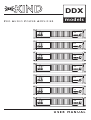
KIND DDX models Power Amplifiers
12. Do not block intake
or exhaust ports. Do
not operate equipment
on a surface or in an
environment which may
impede the normal flow
or air around the unit,
such as a bed, rug,
weathersheet, carpet, or
completely enclosed
rack. If the unit is used
in an extremely dusty or
smoky environment, the
unit should be periodically "blown free" of
foreign matter.
13. Do not remove the
cover. Removing the
cover will expose you to
potentially dangerous
voltages. There are no
user serviceable parts
inside.
14. Connecting amplifier outputs to oscilliscopes or other test
equipment while the
amplifier is in bridged mode may damage
both the amplifier and
test equipment.
15. Do not drive the inputs
with a signal level greater than that required to
drive equipment to full
output.
16. Do not connect the
inputs/outputs of
amplifiers or consoles to any other voltage source, such as a
battery, mains source, or
power supply, regardless
of whether the amplifier
or console is turned on
or off.
17. Do not run the output of any amplifier
channel back into
another channel's
input. Do not parallel-or series-connect
an amplifier output
with any other amplifier output. KIND is
not responsible for
damage to loudspeakers
for any reason.
18. Do not ground any
red ("hot") terminal.
For connection of "hot"
terminals to get parallel
high current mode see
appropriate paragraph.
19. Non-use periods. The
power cord of equipment should be unplugged from the outlet
when left unused for a
long period of time.
20. Service information.
Equipment should be
serviced by qualified service personnel when:
A. The power supply cord
or the plug has been
damaged;
B. Objects have fallen, or
liquid has been spilled
into the equipment;
C . The equipment has
been exposed to rain;
D. The equipment does
not appear to operate
normally, or exhibits a
marked change in
performance;
E. The equipment has been
dropped, or the enclosure damaged.
21. To obtain service,
contact your nearest
KIND Service Center,
Distributor, Dealer, or
KIND Audio (Italy).
Page 2
MCX
DDX
models
models
Indice
Table of Contents
Warranty Information
Declaration of Conformity
User Responsibility
Introduction
Unpackaging
Installation / Mounting
Front - Rear Panel / Side View
Operation
Configuration
Protection Features
Service Information
Technical Specifications
Page 3
4
5
5
6
6
6
7
10
13
14
15
16
Informazioni per la Garanzia
Dichiarazione di Conformità
Responsabilità dell’ utente
Introduzione
Disimballaggio
Installazione / Montaggio
Vista Fronte-Retro-fianco
Utilizzo
Configurazione
Caratteristiche delle Protezioni
Informazioni sulla Manutenzione
Specifiche Tecniche
4
5
5
6
6
6
7
10
13
14
15
16
KIND DDX models Power Amplifiers
DDX
models
WARRANTY
INFORMATION
INFORMAZIONI PER LA
G A R A N Z I A
INFORMATIONS
DE
G A R A N T I E
GARANTIE-NACHRICHT
(ITALY only; see your dealer
or distributor)
(Solo per l’Italia; Consultate
il vostro Rivenditore o
Distributore)
(ITALIE seulement; consultez votre marchand ou
distributeur)
(nur beim ITALIEN; Ihrem
Fachhändler konsultieren)
Disclaimer
Esonero
KIND Audio, is not liable for any
damage to speakers, amplifiers,
or any other equipment that is
caused by negligence or improper installation and/or use of the
DDX model amplifier.
Product Warranty
KIND Audio guarantees the
DDX models to be free from
defective material and/or workmanship for a period of three
years (1095 days) from the date
of sale, and will replace defective
parts and repair malfunctioning
products under this warranty
when the defect occurs under
normal installation and use--provided the unit is returned to our
factory via prepaid transportation with a copy of the proof of
purchase, i.e., sales receipt. This
warranty provides that examination of the returned products
must indicate, in our judgment, a
manufacturing defect. This warranty does not extend to any
product which has been subjected to misuse, neglect, accident,
improper installation, or where
the date code has been removed
or defaced.
KIND audio, non è responsabile
per danni causati dalla negligenza
oppure dall’ errata installazione o
dall’uso improprio di questo
amplificatore modello DDX
verso altoparlanti, amplificatori o
altro materiale.
Garanzia del prodotto
KIND audio garantisce i modelli
DDX per un periodo di tre anni
(1095 giorni) da difetti dei materiali e/o costruzione, sostituirà le
parti difettose e riparerà i prodotti malfunzionanti durante
questo periodo, solo quando il
difetto avviene con un uso e una
installazione normale.
L’unità deve essere ritornata alla
nostra fabbrica in porto franco
con allegata fattura o scontrino
fiscale che ne provi l’acquisto.
Questa garanzia prevede un
esame del prodotto ritornato,
per la verifica di eventuali difetti
di costruzione, il giudizio su questa materia rimane nostro e
insindacabile.
Questa garanzia non si estende a
prodotti che sono stati soggetti
ad un uso sbagliato, negligenza,
incidente, impropria installazione,
oppure dove i dati o i codici
sono stati rimossi o cancellati.
KIND DDX models Power Amplifiers
Page 4
MCX
DDX
models
models
APPROVALS
OMOLOGAZIONI
HOMOLOGATIONS
This equipment conforms to the
requirements of the EMC directive 89/336/EEC, amended by
92/31/EEC and 93/68/EEC and
the requirements of the Low
Voltage Directive 73/23/EEC,
amended by 93/68/EEC.
Standard Applied:
EN55103-1 (Emissions)
EN55103-2 (Immunity)
EN60065, Class I (Safety)
Il presente dispositivo è conforme ai requisiti della Direttiva
Compatibilità Elettromagnetica
89/336/CEE, e relative integrazioni 92/31/CEE e 93/68/CEE, ed ai
requisiti della Direttiva Bassa
Tensione 73/23/CEE, e relativa
integrazione 93/68/CEE.
Norme Applicate:
EN55103-1 (Emissioni)
EN55103-2 (Immunità)
EN60065, Classe I (Sicurezza)
Le présent équipement est
conforme aux exigences de la
directive EMC 89/336/CEE, modifiée par les directives 92/31/CEE
et 93/68/CEE et aux exigences
de la directive « Basse tension »
73/23/CEE, modifiée par la directive 93/68/CEE.
Normes appliquées:
EN55103-1 (Emission)
EN55103-2 (Immunité)
EN60065, Catégorie I (Sécurité)
User Responsibility
Responsabilità dell’utente
SPEAKER DAMAGE
Your amplifier is very
powerful and can be
potentially dangerous to both, loudspeakers and humans alike. Many
loudspeakers can be easily damaged or destroyed by overpowering, especially with the high
power available from a bridged
amplifier. Always check the
speakers’ continuous and peak
power capabilities. Even if the
amplifier’s front panel attenuators can be used to reduce the
gain, it is still possible to reach
full output power if the input
signal level is high enough.
HAZARD OUTPUT
VOLTAGES
Power amplifiers are
capable of producing
hazardous output
voltages (on speaker connector).
To avoid electrical shock, do not
touch any exposed speaker
wiring while the amplifier is operating.
RADIO INTERFERENCE
A sample of this product has
been tested and complies with
the limits for the European
Electro Magnetic Compatibility
(EMC) directive. These limits are
designed to provide reasonable
protection against harmful interference from electrical equipment. This product uses radio
frequency energy and if not used
or installed in accordance with
these operating instructions, may
cause interference to other
equipment, such as radio receivers. However, there is no guarantee that interference will not
occur in a particular installation.
If this equipment does cause
harmful interference to radio or
television reception, which can
be determined by turning the
equipment on and off, the user is
encouraged to try to correct the
interference by one or more of
the following measures:
•Reorient or relocate the antenna.
•Increase the separation between
the equipment and receiver.
•Connect the equipment into an
outlet on a circuit different from
that to which the receiver is connected.
Page 5
ALLGEMEINE
STANDARDS
Dieses Gerät entspricht den
Anforderungen der EMCDirektive 89/336/EEC, erweitert
durch 92/31/EEC und 93/68/EEC,
sowie den Anforderungen der
N i e d e r s p a n nu n g s - D i re k t i ve
73/23/EEC, erweitert durch
93/68/EEC.
Bezogen auf die Standards:
EN55103-1 (Emissions)
EN55103-2 (Immunität)
EN60065, Class I (Sicherheit)
DANNI AGLI ALTOPARLANTI
Questo amplificatore
è
estremamente
potente e può essere potenzialmente pericoloso sia
per gli altoparlanti che per l’uomo. La maggior parte degli altoparlanti può danneggiarsi o rompersi facilmente, in particolare a
causa della potenza elevata erogata da un’amplificatore usato a
ponte. Verificare sempre la
potenza di picco e continua degli
altoparlanti. Anche se il guadagno
viene ridotto tramite gli attenuatori sul pannello frontale dell’amplificatore, è ancora possibile raggiungere la massima potenza di
uscita se il livello del segnale in
ingresso è sufficientemente alto.
TENSIONI IN USCITA PERICOLOSE
Gli amplificatori
sono in grado di
generare tensioni di
uscita pericolose (al connettore
degli altoparlanti). Per prevenire
il rischio di scossa elettrica, non
toccare gli eventuali cavi scoperti
degli altoparlanti con l’amplificatore in funzione.
INTERFERENZE RADIO
Un campione di questo prodotto
è stato testato ed omologato in
conformità ai limiti della
Direttiva
Compatibilità
Elettromagnetica (EMC). Questi
limiti sono stati definiti per fornire una protezione ragionevole
dalle interferenze pericolose dei
dispositivi elettrici. Questo prodotto utilizza le radiofrequenze
e, qualora non sia installato o utilizzato nel rispetto delle presenti
istruzioni per l’uso, può interferire con altri dispositivi, ad esempio ricevitori radio. Tuttavia, non
è garantito che non si verifichino
interferenze in una particolare
installazione.
Qualora il dispositivo interferisca
con la ricezione di radio o televisione (tale condizione può essere
verificata accendendo e spegnendo il dispositivo), l’utente deve
tentare di eliminare l’interferenza
adottando una o più delle
seguenti misure:
•Riorientare o spostare l’antenna.
•Aumentare la distanza tra dispositivo e ricevitore.
•Collegare il dispositivo ad una
presa posta su un circuito differente rispetto a quella a cui è
collegato il ricevitore.
KIND DDX models Power Amplifiers
DDX
models
•Check if the affected unit complies with the EMC limits for
immunity, (CE-labelled). If not,
address the problem with the
manufacturer or supplier. All
electrical products sold in the EC
must be approved for immunity
against electromagnetic fields,
high voltage flashes, and radio
interference.
•Consult the dealer or an experienced radio/TV technician for
help.
• Verificare che l’unità interessata
sia conforme ai limiti di immunità
EMC (deve recare il marchio
CE). In caso contrario, contattare
il produttore o rivenditore.Tutti i
dispositivi elettrici venduti nella
CEE devono essere omologati
relativamente all’immunità da
campi elettromagnetici, alte tensioni ed interferenze radio.
•Rivolgersi ad un rivenditore
oppure ad un tecnico radio/TV
esperto.
Introduction
Introduzione
Congratulations on your purchase of a KIND audio power amplifier. We would like to thank you
for your confidence in us and
our products. The power amplifier was hand-made in Italy. All
the components were specially
selected. Although the amplifier
was designed to allow straightforward and uninterrupted
operation, improper handling or
incorrect installation could
damage the power amplifier.
Your amplifier represents the
latest technology in power amplifier design. Please read this
manual carefully as it contains
information vital to the safe operation of your amplifier.
Unpacking
Check the carton box and its
contents immediately to see if
there is any sign of damage.
Upon unpacking inspect the
amplifier, if you detect any damage inform the forwarding agent
without delay and ask for the
damage to be documentated.
Claims can only be made against
the forwarder agent by the consignee. Be sure to save the carton and all packaging materials
for the carrier's inspection.
It's a good idea to save the carton and packing material even if
the amplifier has arrived in good
condition. Should you ever need
to ship the unit back to KIND, or
one of its Service Center.
Using only the original factory
packaging will be the best way to
save the unit from carrier negligence.
Installation/Mounting
All DDX models amplifiers are
2-rack space units that can
mount in a standard 19" rack.
Four front panel mounting holes
are provided. Rear mounting ears
give additional support especially
important in mobile sound
systems.
The unit should not to be installed
in a location with:
•Too high ambient temperatures,
dust build-up or excessive humidity;
•Fog machines output’s oriented
to the area of the amplifier;
•Exhaust air ventilators and similar units near the area of the
amplifier;
•With permanent vibrations;
•With excessive induction or
magnetic fields due to tranformers and transmitters;
Congratulazioni per il vostro
acquisto di un'amplificatore di
potenza audio KIND. Noi vogliamo ringraziarvi per la fiducia che
date a noi e ai nostri prodotti. Il
vostro amplificatore é stato
costruito a mano in Italia. Tutti i
componenti sono stati selezionati. Sebbene l'amplificatore sia
stato progettato per permettere
il funzionamento continuo, l'uso
improprio o un'installazione
scorretta potrebbero danneggiarlo. Il vostro amplificatore rappresenta la tecnologia più avanzata
nel progetto di un'amplificatore
di potenza.Vi preghiamo di leggere questo manuale attentamente
in quanto contiene informazioni
vitali per un utilizzo sicuro del
vostro amplificatore.
Disimballaggio
Controllate l'imballo in cartone e
il suo contenuto immediatamente per vedere se ci sono segni di
danneggiamento. Dopo il disimballaggio ispezionate l'amplificatore, se verificate qualche danno
informate lo spedizioniere senza
ritardo e chiedete che il danno
venga documentato. I reclami allo
spedizioniere possono essere
fatti solamente dal destinatario.
Assicuratevi di conservare l'imballo completo per l'ispezione
dello spedizioniere. E' buona idea
conservare l'imballo completo
anche se l'amplificatore arriva in
condizioni ottimali, potreste
averne bisogno per rispedirlo a
KIND o a uno dei suoi Centri
Assistenza. Usate solamente l'imballo originale, sarà il miglior
modo per salvaguardare l'apparecchiatura dalla non curanza
degli spedizionieri.
Installazione/Montaggio
Tutti i modelli di amplificatori
DDX sono 2 unità, possono
essere montati in un rack 19"
standard, sono previsti 4 fori sul
pannello frontale per il montaggio. Per avere un fissaggio ottimale, importante nei sistemi mobili,
supporti addizionali sono presenti sul retro.
L’unità non dovrebbe essere installata in posti con:
•Temperatura in ambiente troppo alta, troppa polvere o eccessiva umidità;
•L’uscita di macchine del fumo
orientata nell’area dell’amplificatore;
•Ventilatori di scarico e simili
unità vicino all’area dell’amplificatore;
•Con vibrazioni permanenti;
•Con eccessiva induzione dovuta
al campo magnetico di trasformatori e trasmettitori;
KIND DDX models Power Amplifiers
Page 6
MCX
DDX
models
models
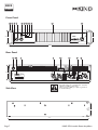
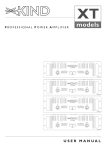
Front Panel
1
2
3
4
6
5
7
8
9
11
10
PROTECT
PRO AUDIO POWER AMPLIFIER
CLIP/LIM
-10dB
EXP
-20dB
-5
-20
ACTIVE
-1
0dB
-80
76mm
-5
-16
-3 -20
-40
POWER
-12 -10 -7
-12 -10 -7
-16
3842
HI-TEMP
SIGNAL
88mm
DDX
-3
-1
0dB
-40
-80
Ch A
Ch B
TEOTON PATENTED TECHNOLOGY
483mm
Rear Panel
15
RISK OF ELECTRIC SHOCK DO NOT OPEN
MADE IN ITALY - E.U.
OUTPUTS
19
DATA PORT
KIND Audio
Galliate NO, Italy
Made in E.U.
Model: DDX3222
Output PWR per CH/Imp: 1100/4
95-265VAC 50/60Hz 900VA PFC
17
INPUTS
1+
12+
2-
SERIAL
BARCODE
0000000
B
A
16
1+
2-
OUTPUT PINOUTS
STEREO
OUT A OUT B
Ch.A + Ch.B +
Ch.A - Ch.B Ch.B + Ch.A +
Ch.B - Ch.A BRIDGE
OUT A
Spk +
Spk -
PUSH
B
+
-
INPUT
XLR
P2
P3
P1
PINOUTS
1/4
TIP
RING
SLEEVE
STEREO
18
30/75Hz Hi Pass Filter
Internal Set Per Channel
PUSH
HPF-A ON
CAUTION !
88mm
12
HPF-B ON
LINK/BRIDGE ON
13 14
A
432mm
Do not adjust the configuration switches
while the amplifier is turned on.
Never connect a hot (+) output to ground or
to another hot (+)
Side View
76mm
455mm
Page 7
KIND DDX models Power Amplifiers
DDX
models
1. Rack mounting ears
1. Supporti di montaggio
2. Standard rack handles
2. Maniglie rack standard
3. Input attenuators
3.Attenuatori di ingresso
4. Signal bar LED
4. Signal barra LED
5. Clip/Limiter LED
5. Clip/Limiter LED
Two front panel mounting holes
are provided on each mounting
ear.
Comfortable handles are provided for easy transport and
mounting operation.
Two front panel precision 21
steps input attenuators adjust
level for their respective amplifier channels. Minimum attenuation (-0dB) equals maximum output. In the bridge mode both
level attenuators must be at the
same position. We recommend
that you set them to the -0dB
(full) position.
Each channel has a bar LED, as
the input signal strength increases, the green SIGNAL, -20dB,
and yellow -10dB LED indicators
light respectively at 0.1%, 1%, and
10% of full power.
Each channel has a LED that light
at the real clipping point (more
than 0.5% T.H.D.) and indicates
also: clip limiter, L.S.C. (Load
Security Control) engaged circuits.
6. Protect LED
Each channel has a Protect LED
that will light when: the load connected is lower than 1 Ohm, the
amplifier’s output as been shorted.
7. Exp LED
The unit has one Exp LED that
will light when an optional
expansion board like a DSP or
remote control will plugged inside the unit.
8. Hi-Temp LED
Due fori per il montaggio, ogni
lato, sono previsti sul pannello
frontale.
Comode maniglie sono fornite
per facilitare operazioni di trasporto e montaggio.
Due attenuatori di precisione a
21 posizioni regolano il livello del
loro rispettivo canale dell'amplificatore. Minima attenuazione (0dB) uguale a massima uscita.
Nell'uso in mono a ponte
entrambi gli attenuatori di livello
devono essere nella stessa posizione. Si raccomanda di impostarli sulla posizione -0 dB (full).
Ogni canale ha una barra LED,
col salire del segnale d’ingresso, i
LED verdi SIGNAL, -20dB, e giallo -10dB si illuminano rispettivamente al 0.1%, 1%, e 10% della
massima potenza.
Ogni canale ha un LED che si
illumina al punto di clip reale
(oltre lo 0.5% T.H.D.) e indica
anche: l'intervento del limiter e
l’intrervento dell’L.S.C. (Load
Security Control).
6. Protect LED
Ogni canale ha un LED di protezione che si illumina quando: il
carico collegato è al di sotto di 1
Ohm, l’uscita dell’amplificatore è
stata cortocircuitata.
7. Exp LED
L’unità ha un LED Exp che si illumina quando una board di espansione opzionale come un DSP o
un controllo remoto viene inserita all’interno dell’unità.
8. Hi-Temp LED
In case of inadequate ventilation
the heatsink temperature will
start to rise. At 60°C the the HiTemp LED will start to blinking
and the output power will be
gradually reduced. At 75°C the
Hi-Temp LED will remain light
on, and both channels will be
muted until temperature decrease to normal operating level with
an automatic reset system.
In caso di ventilazione inadeguata
la temperatura del dissipatore
comincerà ad alzarsi. A 60°C il
LED Hi-Temp comincerà a lampeggiare e la potenza d’uscita
verrà gradualmente ridotta. A
75°C il LED Hi-Temp rimarrà
acceso, e ambedue i canali
andranno in mute fino a che la
temperatura torna ad un livello
normale, il reset avviene in automatico.
9.Active LED
9.Active LED
10.AC power switch
10. Pulsante di accensione
The green active LED illuminates
to indicate that the amplifier is
turned on, and works correctly.
Use this to switch on the amplifier. A soft-start system limits the
start-up surges.
11. Fan intake grill filter
One grill with foam filter is located on the front panel to prevent
dust from entering the amplifier.
For easy cleaning of the filter the
grill is removable by simply pulling it off. The foam filter should
always be used. The fan’s variable
Il LED verde active si illumina per
indicare che l'amplificatore é
acceso e lavora correttamente.
Usatelo per accendere l'amplificatore. Un sistema di soft-start
limita l'assorbimento all’accensione.
11. Griglia di aspirazione
del ventilatore e filtro
Sul pannello frontale si trova una
griglia con filtro in spugna per
prevenire l’ingresso della polvere
nell’amplificatore. Per la pulizia
del filtro, la griglia può essere
rimossa semplicemente tirandola.
KIND DDX models Power Amplifiers
Page 8
MCX
DDX
models
models
speed control ensure low noise
operation and adapt the quantity
of air required from the actual
temperature inside the unit.
Thanks to this advanced system
low noise is guarantee. Do not
block this intake!
12. Fan exhaust ports
Heated air exits the amplifier
through the exhaust ports, located on the rear of the amplifier
chassis. Be sure not to block this
ports, especially when rackmounting the amplifier.
13. A.C. Power cable
The unit have one A.C. power
cable. Before connection, be sure
that the cable is not frayed or
broken. The connection must be
made only in a plug with the
electrical ground wire system.
14. S.N. label
Every unit has a label indicating:
the model, the output power, the
main voltage, the power requirement and the barcode serial
number.
15. Speakon output connectors
The unit has two Speakon connectors as outputs: A and B.
Every one permit the connection
of both channels for stereo operation or parallel mode. For
bridge operation the A connector should be used. For reference
see drawings 1-3.
16. Mode operation switches
Setup these switches for the
desired operation mode. For
reference see drawings 1-3.
17. Input connectors
Combo (XLR female with phone
jack 6.3mm (¼”)) and a Europlug
connectors are provided on each
channel for balanced or unbalanced input. Unfortunate wiring, in
the proximity of dimmers or
other generalised phase controls,
motors, transformer, etc. can
cause interference into your
system. You will hear loud humming or a bumping noise in the
loudspeakers. Balanced wiring
suppresses these noises quite
significantly. For wiring see
drawings on page 12.
18. Selectable low frequency filter
The switch enable the filter circuit located on settings board.
For setup see page 13.
19. Data Port
This port can be used as In/Out
connections with the optional
expansion boards as DSP and
WinArc Remote control. For
more information refer to DSP
or WinARC user manual.
Page 9
Il filtro in spugna dovrebbe sempre essere usato. Il controllo a
velocità variabile della ventola
assicura un basso rumore operativo e adatta la quantità di aria
richiesta in base alla temperatura
reale all'interno dell'unità. Grazie
a questo sistema é garantito un
basso rumore operativo. Non
ostruite questa apertura!
12.Aperture di scarico del
ventilatore
L'aria per il raffreddamento dell'amplificatore viene scaricata sul
retro dell'amplificatore attraverso le aperture di scarico, non
ostruite queste aperture quando
montate a rack l'amplificatore.
13. Cavo di alimentazione A.C.
L’unità ha un cavo di alimentazione A.C.. Prima di connetterlo,
controllare che non sia spelato o
rotto. La connessione va fatta
solo in una presa che abbia il
sistema di messa a terra.
14. Etichetta S.N.
Ogni unità ha una etichetta indicante: il modello, la potenza d’uscita, il voltaggio di alimentazione,
l’assorbimento e il numero di
serie in codice a barre.
15. Connettori di uscita
speakon
L’unità ha due connettori
Speakon come uscite: A e B.
Ognuno permette la connessione
di ambedue i canali, nell’uso in
stereo e parallel. Per l’uso in
bridge il connettore A deve essere usato. Come riferimento vedi
disegni 1-3.
16. Switch per il modo
d’uso
Impostare questi switch per l’utilizzo desiderato. Come riferimento vedi disegni 1-3.
17. Connettori di ingresso
Connettori Combo (femmina
XLR con jack 6.3mm) e Europlug
sono forniti per ogni canale per
l’ingresso bilanciato o sbilanciato.
Cablaggi in prossimità di dimmer
o altri controlli di fase, motori,
ecc. possono causare interferenze nel vostro sistema. Si sentiranno rumori come ronzii o scariche
negli
altoparlanti.
Connessioni bilanciate sopprimono significativamente questi
rumori. Per il cablaggio vedi disegni a pagina 12.
18. Filtro selezionabile
per le basse frequenze
Lo switch attiva il circuito di filtro situato sulla scheda dei settaggi. Per il setup vedi pagina 13.
19. Porta Dati
Questa porta viene usata come
connessione Ingresso/Uscita con
le schede d’espansione opzionali
come DSP e WinArc Controllo
remoto. Per maggiori informazioni riferirsi al manuale d’uso del
DSP o del WinARC.
KIND DDX models Power Amplifiers
DDX
models
Operation
Utilizzo
Connecting Power and
Circuit size requirements
Connessione alla rete e
assorbimento
Amplifier’s power requirement
are rated at idle, at 1/8 and 1/3
power ("severe" music condition). The maximum power current draw rating is limited only
by the internal fuses. Consult the
specification at the end of this
manual for the power each
amplifier will demand. Mains voltage must also be correct and
the same as that printed on the
rear of the amplifier. Damage
caused by connecting the amplifier to improper AC voltage is
not covered by any warranty.
Note: always switch off and
disconnect the amplifier from
mains voltage before making
audio connections, and as an
extra precaution, have the attenuators turned down during
power-up.
Cooling Requirements
Amplifier use a forced air cooling
system to maintain a low, even
operating temperature.
Drawn by a infinitely variable
speed fans mounted inside the
unit, air enters through the front
grills with dust filter, and courses
through the cooling fins of the
heatsinks, which dissipates power
transistor heat, before exiting
through the rear panel ports.
Make sure that there is enough
space around the front of the
amplifier to allow air to enter,
and around the units to allow the
heated air to exit. If the amp is
rack-mounted, do not use doors
or covers on the front and rear
of the rack; the air must flow
through the amplifier without
resistance. Note: whatever type
of rack you are using, make sure
that the heated air can escape
freely, and that there is not resistance to the intake of cool air
through the front grill.
L’assorbimento dell’amplificatore
è stimato a riposo, a 1/8 e a 1/3
della potenza ("severa" condizione musicale). L'assorbimento
massimo di corrente é limitato
solamente tramite i fusibili interni. Consultate le specifiche alla
fine di questo manuale per la
potenza che occorrerà all'amplificatore. Il voltaggio deve corrispondere a quello stampato sul
retro dell'amplificatore. Danni
causati da una connessione a un
voltaggio improprio non sono
coperti da nessuna garanzia.
Note: spegnete sempre e disconnettete l'amplificatore dall'alimentazione prima di fare connessioni audio, e come extra precauzione tenete gli attenuatori al
minimo durante l'accensione.
Raffreddamento
L'amplificatore usa un sistema ad
aria forzata per mantenere bassa
la temperatura operativa.
Ventola/e a velocità variabile
montata/e all'interno dell’unità
introducono l'aria nell'unità tramite la griglia con filtro antipolvere posta sul fronte. L'aria passa
attraverso le alette di raffreddamento dei dissipatori, dissipando
il calore generato dai transistor,
prima di essere scaricata attraverso le aperture sul pannello
retro. Fate in modo di lasciare
sufficiente spazio sul fronte dell'amplificatore per permettere
all'aria di entrare e intorno all'unità per permettere all'aria calda
di uscire. Se l'amplificatore é
montato a rack, non usate porte
o coperchi sul fronte e sul retro
del rack; l'aria deve fluire attraverso l’amplificatore senza resistenza. Note: qualunque tipo di
rack stiate usando, accertatevi
che l'aria calda possa uscire liberamente e che non ci sia resistenza all'ingresso dell’aria fredda
attraverso la griglia sul fronte.
Configurazione
Configuration
Utilizzare gli switch e i jumper
interni di configurazione per configurare l’amplificatore secondo
le vostre esigenze. Le impostazioni vanno eseguite con l’unità
spenta.Tramite gli switch e i jumper è possibile configurare l’amplificatore per le seguenti funzioni:
Input Sensitivity/Gain (internal jumpers)
The Factory set is 32dB Gain.
The standard settings are: 26dB32, selection is independent for
each channel. Use this function
to match the amplifier’s gain with
the other connected equipment.
As option, is possible adjust the
unit for any sensitivity/gain. Note
that every increase of the gain
will decrease the S/N ratio. For
setup see page 13.
Sensibilità/Guadagno d’ingresso (jumper interni)
Il settaggio in Fabbrica è 32dB. I
settaggi standard sono: 26dB32dB, la selezione è indipendente
per ogni canale. Questa funzione
va usata per accoppiare il guadagno dell’amplificatore con gli altri
apparecchi connessi. Come
opzione, è possibile settare l’unità per ogni sensibilità/guadagno.
E’ da notare che ogni incremento
del guadagno abbasserà il rapporto S/N. Per il setup vedi pagina
13.
Use the configuration switch and
the internal jumpers to configurate the amplifier to meet your
requirements. The setup must be
done with the unit switched off.
With the switches and jumpers is
possible to configurate the amplifier for the following functions:
KIND DDX models Power Amplifiers
Page 10
MCX
DDX
models
models
Selectable low frequency
filter
One of the advantages of your
amplifier, that will let you expand
the application range, is the builtin filter: each channel has its own
internal selectable LF filter. This
filter attenuates the signal level
of frequencies beneath 30 or
75Hz and allows the amplifier to
be optimized to the speaker
system. When the filter is switched off, the input rolls off at
5Hz to protect from DC
inputs.These filters can be used
to:
• Cut low frequencies for loudspeaker equipped with small LF
drivers.
• Cut low frequencies for 100V
transformed distribution line.
For setup see page 13.
Stereo Mode (standard)
In stereo mode, the channels
operate independently, with their
input attenuators controlling the
respective channel’s level.
Recommended minimum nominal load impedance for stereo
operation is 4 or 2 Ohms per
channel (as indicated on the specifications). Either the input connectors, Combo or Europlug may
be used to connect the signal to
their respective channel.
Loudspeakers are connected to
the speakon outputs A or B. For
reference see drawings 1-3. For
bench test read the note on page
15.
Bridged Mono Mode
In Bridged Mono mode, both
amplifier channels work with the
same input signal, but with inverse phases.The result is a doubling
of the output voltage and thus
double the power on the double
impedance. If the amplifier is to
be operated in Bridged Mono
mode, ONLY one input may be
used, A or B. Both level attenuators must be at the same position.We recommend that you set
them to the -0dB (full) position.
Either the input connectors,
Combo or Europlug may be used
to connect the input signal.
Loudspeakers are connected to
the speakon output A. For reference see drawings 1-3.
Parallel Inputs (Link)
In parallel mode both channels'
inputs are linked and receive the
same signal. The parallel mode is
active if the Link switches are in
position "ON". Both level attenuators are active, allowing you
to set different levels for each
channel. Note that only the
inputs are connected in parallel.
This is NOT a parallel mono
mode. Never connect either
positive output terminal to
ground or in parallel.You may use
the remaining input connectors
to carr y the signal to other
amps. NOTE:Always turn off the
Link switch when using the
amplifier for Bi-amping.
Page 11
Filtro selezionabile per le
basse frequenze
Uno dei vantaggi del vostro
amplificatore, che vi consentirà di
espandere la sua gamma di applicazioni, è quello di essere equipaggiato con un filtro: ogni canale
ha al suo interno un filtro LF
selezionabile. Questo filtro attenua il livello delle frequenze al di
sotto dei 30 o 75Hz e permette
all’amplificatore di essere ottimizzato per il sistema di altoparlanti. Quando il filtro è disinserito, le frequenze al di sotto dei
5Hz sono comunque attenuate
per proteggere l’ingresso dalla
DC. Questo filtro può essere
usato per:
• Tagliare le LF a diffusori che
montano piccoli driver per le
basse frequenze.
• Tagliare le LF a trasformatori di
linea per distribuzione a 100V.
Per il setup vedi pagina 13.
Uso in stereo (standard)
Nell'uso in stereo i canali operano in modo indipendente, con i
loro attenuatori d’ingresso che
controllano il rispettivo livello
del canale. Il carico minimo raccomandato per l'uso in stereo è
4 o 2 Ohms per canale (come
indicato nelle specifiche).
Entrambi i connettori d’ingresso,
Combo o Europlug possono
essere usati per connettere il
segnale al loro rispettivo canale.
Gli altoparlanti sono collegati ai
connettori di uscita speakon A o
B. Come riferimento vedi disegni
1-3. Per il test da banco leggere la
nota a pagina 15.
Uso in mono a ponte
Nell’uso in mono a ponte, ambedue i canali dell’amplificatore funzionano con lo stesso segnale
d’ingresso, ma con fasi invertite. Il
risultato è il raddoppio del voltaggio d’uscita e questo raddoppia la potenza sul doppio dell’impedenza. Se l’amplificatore deve
operare in mono a ponte SOLO
un ingresso deve essere usato, l’A
o il B. Nell'uso a ponte entrambi
gli attenuatori di livello devono
essere nella stessa posizione. Si
raccomanda di impostarli sulla
posizione -0 dB (full). Entrambi i
connettori d’ingresso, Combo o
Europlug possono essere usati
per connettere il segnale d’ingresso. Gli altoparlanti sono collegati al connettore d’uscita
speakon A. Come riferimento
vedi disegni 1-3.
Ingressi in parallelo (Link)
Nel modo parallel, gli ingressi di
entrambi i canali sono collegati e
ricevono lo stesso segnale. Il
modo parallel è attivato quando
gli switch Link sono in posizione
"ON". Entrambi gli attenuatori di
livello sono attivi, quindi è possibile impostare un livello differente per ogni canale. Tuttavia, soltanto gli ingressi sono collegati in
parallelo. Questo NON è un
parallel mono. Non collegare mai
i terminali di uscita positivi a
massa oppure in parallelo.
Potreste usare i connettori d’ingresso rimanenti per collegare
altri amplificatori. NOTA:
Disinserire sempre gli switch
Link quando si utilizza l’amplificatore per il Bi-amping.
KIND DDX models Power Amplifiers
DDX
models
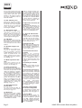
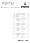
Input Wiring / Input - Output Mode Connections
Balanced Connection
shield
MADE IN ITALY - E.U.
OUTPUTS
DATA PORT
KIND Audio
Galliate NO, Italy
Made in E.U.
Model: DDX3222
Output PWR per CH/Imp: 1100/4
95-265VAC 50/60Hz 900VA PFC
INPUTS
1+
12+
2-
SERIAL
BARCODE
6.3mm (1/4-inch) TRS, XLR and Europlug
0000000
B
A
1+
2-
OUTPUT PINOUTS
STEREO
OUT A OUT B
Ch.A + Ch.B +
Ch.A - Ch.B Ch.B + Ch.A +
Ch.B - Ch.A BRIDGE
OUT A
Spk +
Spk -
PUSH
+
-
INPUT
XLR
P2
P3
P1
PINOUTS
1/4
TIP
RING
SLEEVE
B
30/75Hz Hi Pass Filter
Internal Set Per Channel
PUSH
HPF-A ON
RISK OF ELECTRIC SHOCK DO NOT OPEN
HPF-B ON
LINK/BRIDGE ON
CAUTION !
shield
inverting
non-inverting
A
STEREO
Unbalanced Connection
shield
jumper
jumper
Ch B
Ch A
Ch A
Ch B
jumper
1. Stereo Mode
6.3mm (1/4-inch) TRS, XLR and Europlug
MADE IN ITALY - E.U.
OUTPUTS
DATA PORT
KIND Audio
Galliate NO, Italy
Made in E.U.
Model: DDX3222
Output PWR per CH/Imp: 1100/4
95-265VAC 50/60Hz 900VA PFC
INPUTS
1+
12+
2-
SERIAL
BARCODE
0000000
B
A
1+
2-
OUTPUT PINOUTS
STEREO
OUT A OUT B
Ch.A + Ch.B +
Ch.A - Ch.B Ch.B + Ch.A +
Ch.B - Ch.A BRIDGE
OUT A
Spk +
Spk -
PUSH
+
-
INPUT
XLR
P2
P3
P1
PINOUTS
1/4
TIP
RING
SLEEVE
B
30/75Hz Hi Pass Filter
Internal Set Per Channel
PUSH
HPF-A ON
RISK OF ELECTRIC SHOCK DO NOT OPEN
HPF-B ON
LINK/BRIDGE ON
CAUTION !
A
STEREO
IMPORTANT NOTE:
Use ONLY one input Ch A or B.
Use Ch A speakon connector (see wiring).
Use both level attenuators set at the same position. We recommend that you set them to the 0dB (full) position.
2. Bridged Mono Mode
MADE IN ITALY - E.U.
OUTPUTS
DATA PORT
KIND Audio
Galliate NO, Italy
Made in E.U.
Model: DDX3222
Output PWR per CH/Imp: 1100/4
95-265VAC 50/60Hz 900VA PFC
INPUTS
1+
12+
2-
SERIAL
BARCODE
0000000
B
A
1+
2-
OUTPUT PINOUTS
STEREO
OUT A OUT B
Ch.A + Ch.B +
Ch.A - Ch.B Ch.B + Ch.A +
Ch.B - Ch.A BRIDGE
OUT A
Spk +
Spk -
PUSH
+
-
INPUT
XLR
P2
P3
P1
PINOUTS
1/4
TIP
RING
SLEEVE
B
STEREO
30/75Hz Hi Pass Filter
Internal Set Per Channel
PUSH
HPF-A ON
RISK OF ELECTRIC SHOCK DO NOT OPEN
HPF-B ON
LINK/BRIDGE ON
CAUTION !
A
IMPORTANT NOTE:
Read the note for bench test
on page 15.
3. Parallel Inputs (Link)
KIND DDX models Power Amplifiers
Ch B
Ch A
Ch A
Ch B
Page 12
DDX
models
C45
R84
C42
R12
C36
R96
C40
R98
R94
C85
R95
R90
C37
R89
C25
R75
R50
C83
R48
C31 C81 D27
C33
R76
R7 R20 R16
R44
C30
R72
C32
C79
R5
R13
C71
R19
D25
R70
C73
R71
R46
R42
R49
C75
R64
C22
R86
R85
C39
R66
R92
C41
R93
R97
C43 C35
C77
R107
R32
R31
OFFSET-B
C86
C53
R112
C51
C57
R78
DZ4
R77
U10
U13
Q3
U14
Q5
D28
D10
R116
R128
TP4
C91 R159
R164
Q6
R129
R34
C98
C97
C70
R136
R131
R133
TP1
R60
R163
R105 C90
C12
C11
R160
C92
R152 R143 R141
C94
R144
R139
DZ9
R162
R149
Q8 TP6
C44
C89
D26
D8
Q4 Q10
U15
R148
R146
U16
R68
R55
R67
TP5
R29
R161
D21
C67
C48
C6
C102
C46
C66
R147
C13
R145
D17
Q9
R166
Q7
R158
R167
PC200008-00
R88
R87
D22
R157
R168
R56 C62
U17
R27
R103 C88 C49
R127
R156
R154
R155
R153
C101
D18
U11
R170
D5
U9
R165
C68
C65 DZ8
D13
D4
D19 D20
R47
R114
D23
C55
R109
D11
R118
R59
R82
C64
C10
R140
R124 R18
R137
R33
R150
R28 DZ6
C47
RED
VR2
R117
R102
J3
D24
D16
R36
R125
C59
C60
R54
R69
R115
R104
D3 C61
C58 R23
R120
R17
D15
J2
R142
C93
R138
J1
R122
TP3
R63
C19
C27
D14
DZ5
C84
CONSTANT GAIN-B
J11
R80
J9
SIGNAL-B BYPASS
R61
R6
R30 C82 R79 R62
R37
C80
R45
J13
SENSITIVITY-B
GRE
R110
U8
J10
U6
U4
J12
R9
R8
C24
R10
C18
C14
C72
R101
R24
R169
C96
C95
C69
HPF-C 30HZ
HPF-O 75HZ
C26
C21 R4 R2 C20 R3 R1
C103
R134
Q2
BLU
C38 R151
R74
R132
U2
J4
U1
J6
R22
C74
J5
SIGNAL-A BYPASS
C16
C87
DZ3
R58
C8
R41
C29
C9
C52
C56
R57
R73
R35
R21
C76
R99
TP2
R113
C4
R81
D7
R130
C1
YEL
C3
DZ7
D9
U12
R126
C7
C5
R25
D6
R40
C17
C2
BLK
C78 R111
R15
R135
C28
HPF-C 30HZ
HPF-O 75HZ
GRE
R65 R52
C50
C63 R26
C15
YEL
SENSITIVITY-A
DZ1
D1BLK
R51
R119
R53
R123
R38
BLU
U7
D2
R121
R14
R43
VR1
J7
C54
DZ2
RED
C23
R39
Q1
C34
R100
OFFSET-A
J8
U3
R91
CONSTANT GAIN-A
U5
R11
R83
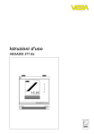
Configuration Mode
DZ10
4. JUMPER SETTINGS BOARD
Frequency Filter Settings
Mode
YELLOW Jumper
J4 (Ch A)
J12 (Ch B)
Position Open= 75Hz
Position Close= 30Hz
Default Position: Close
NOTE: The Filters enable is switched from the Rear Pannel.
Selezione Della Frequenza
del Filtro
Jumper GIALLO
J4 (Ch A)
J12 (Ch B)
Positione Aperto= 75Hz
Positione Chiuso= 30Hz
Posizione di Default: Chiuso
NOTE: L’attivazione del filtro
avviene dallo switch sul Retro.
Constant Gain Settings
Mode
BLU Jumper
J6 (Ch A)
J10 (Ch B)
Position Open= 26dB (20x)
Position Close= 32dB (40x)
NOTE: The standard Factory set
is 32dB Gain.
Settaggio Del Guadagno
Costante
Jumper AZZURRO
J6 (Ch A)
J10 (Ch B)
Positione Aperto= 26dB (20x)
Positione Chiuso= 32dB (40x)
NOTE: Il settaggio standard in
Fabbrica è 32dB.
Signal By-pass for DSP and
Remote control Option
Board
GREEN Jumper
J5 (Ch A)
J9 (Ch B)
Position Open= Board Pluged
Position Close= Board Unpluged
Default Position: Close
By-pass del Segnale per
Schede Opzionali DSP e
Controllo remoto
GREEN Jumper
J5 (Ch A)
J9 (Ch B)
Positione Aperto= Scheda
Presente
Positione Chiuso= Scheda non
Presente
Positione di Default: Chiuso
Page 13
KIND DDX models Power Amplifiers
DDX
models
Protection Features
Every model incorporates sophisticate protection features.
Derived from KIND years experience with installer and rental
companies, the group of circuits
is the latest technology for
amplifiers and load protection.
Limiter
The limiter circuit is part of the
amplifier’s protection circuits,
and is not switchable. When
engaged is indicated by illumination of CLIP/LIM LED and the
channel gain will automatically be
reduced, protecting the loudspeakers against the damage for
distorted signal. The limiter function is activated automatically as
soon as the amplifier is overdrived or there is uncontrolled
feedback, oscillation, or an
improper equipment setting or
malfunction upstream from the
amplifier. The normal program
transient will not trigger the limiter; only steady or excessive clipping will.
Thermal Protection
The temperature management
system constantly monitors the
heatsink temperature. If the heatsink reaches 60°C, the Hi-Temp
LED will start to blinking. In this
condition the respecive channel
input signal will decrease automatically until a temperature
balance is reached. If the amplifier’s working conditions still inadequate and the 75°C will be
reached, the Hi-Temp LED stops
blinking and will remain light on,
and both amplifier’s channel will
be muted until temperature
decrease to normal operating
level with an automatic reset
system.
L.S.C.™ Load Security
Control
Caratteristiche delle protezioni
Ogni modello incorpora delle
protezioni sofisticate. Sono derivate dall'esperienza di KIND con
installatori e service, l'insieme dei
circuiti é la più recente tecnologia per la protezione dell'amplificatore e del suo carico.
Limiter
Il circuito limiter è parte delle
protezioni dell’amplificatore e
non è disinseribile. L’intervento è
indicato dall'illuminazione del
CLIP/LIM LED. Il guadagno del
canale sarà automaticamente
ridotto, proteggendo l'altoparlante da danni dovuti al segnale
distorto. La funzione limiter é
attivata automaticamente non
appena l'amplificatore é sovrapilotato oppure quando c'é un
feedback, oscillazioni, equipaggiamento malfunzionante o mal settato a monte dell'amplificatore. I
transienti del normale programma non lo rendono efficace.
Protezione termica
Il sistema di controllo della temperatura monitorizza costantemente la temperatura del dissipatore. Se il dissipatore raggiunge i
60°C, il LED Hi-Temp comincerà
a lampeggiare. In questa condizione il segnale d’ingresso del
rispettivo canale decrescerà
automaticamente fino a che il
bilanciamento con la temperatura viene raggiunto. Se la condizione di lavoro anomala persiste e si
raggiungono i 75°C, il LED HiTemp smetterà di lampeggiare e
rimarrà acceso, e ambedue i
canali andranno in mute fino a
che la temperatura torni ad un
livello normale, il reset avviene in
automatico.
L.S.C.™ controllo di sicurezza sul carico
This system constantly monitors
the current at the amplifier’s output and the input signal status.
When load’s current exceed the
amplifier’s limit, the output voltage will be automatically re-adjusted to keep the amplifier in a
security condition. The L.S.C. will
have a strong interference douring amplifier’s operation when
the connected load is lower than
1 Ohm or in the amplifier’s output there is a non musical signal
(like a sinus wave) for more than
20sec.. The L.S.C. system ensures
a long operative life to the
power devices.
Questo sistema monitorizza
costantemente la corrente all’uscita dell’amplificatore e lo stato
del segnale d’ingresso. Quando la
corrente del carico supera i limiti
dell’amplificatore, il voltaggio in
uscita verrà automaticamente
riadattato per tenere l’amplificatore in condizioni di sicurezza. L’
L.S.C. avrà una forte interferenza,
durante il funzionamento, quando
il carico connesso è minore di 1
Ohm, oppure se in uscita dell’amplificatore vi è un segnale
non musicale (come un’onda
sinusoidale) per più di 20sec.. Il
sistema L.S.C. assicura una lunga
vita operativa ai dispositivi di
potenza.
DC Voltage Protection
Protezione DC
To protect the connected loudspeakers from DC, a DC detection system monitors independently both output channels. If
DC of 7V or higher is present,
(due to a fault in the power
amplifier itself or due to applied
DC on the input), the amplifier
output stage and the SMPS
(Switching Mode Power Supply)
will be inhibited.
Per proteggere gli altoparlanti
collegati dalla DC, un sistema di
rivelazione DC monitorizza in
modo indipendente ambedue i
canali dell’amplificatore. Se una
DC di 7V o maggiore è presente,
(dovuta alla rottura dell’amplificatore stesso oppure dovuta a una
DC applicata in ingresso), lo stadio d’uscita dell’amplificatore e
l’SMPS (l’alimentatore switching)
verranno inibiti.
KIND DDX models Power Amplifiers
Page 14
DDX
models
AC surges limitation
A system of soft-start reduces
the switch on surges, an essential
requirement in multiple amplifiers situation.
AC mains voltage protection
If the AC mains voltage is lower
or higher than the allowed operational voltage (over or undervoltage), the power supply will be
automatically inhibited. Once the
mains voltage is above the minimum start voltage and below its
maximum operating voltage the
amplifier will restart.
Switch on-off transient
A mute circuitry (without relay)
connect with delay and disconnect immediately the load avoiding the switch on-off transient
that can damage the loudspeakers connected to the amplifier.
Note for bench test
1. Channel B is always polarity
reversed on the input, but polarity compensated by feeding the
minus pin on the Channel B output with the output voltage.
Channel A output is connected in
normal polarity mode. By having
channel A and B operating in
opposite polarity, the energy storage in the power supply is more
efficient. This is significant for
signals below 100 Hz (sub bass
etc.) and improves the power
bandwidth. Be sure to use balanced inputs on all measurement
equipment (also oscilloscope
probes) if you are bench testing.
2. The L.S.C. protection features
will have a strong interference
douring amplifier’s test (limiting
the output power) if the amplifier will be drived with a non
musical signal (like a sinus wave)
for more than 20sec..
Service Information
To obtain service, contact your
nearest KIND Service Center,
Distributor, Dealer or KIND
Audio (Italy).
Limitazione assorbimento AC
Un sistema di soft-start riduce
l’assorbimento all’accensione, un
requisito essenziale in una situazione con amplificatori multipli.
Protezione alimentazione
AC
Se la tensione di rete AC è inferiore o superiore alla normale
tensione di esercizio (sovra o
sotto tensione), l’alimentatore
verrà automaticamente inibito.
L’amplificatore si riavvierà quando la tensione di rete sarà superiore alla tensione minima di funzionamento e inferiore alla tensione massima di esercizio.
Transienti dell’accensione-spegnimento
Un circuito di mute (senza relè)
connette con ritardo e disconnette immediatamente il carico,
eliminando i transienti dell’accensione-spegnimento, che possono
danneggiare gli altoparlanti connessi all’amplificatore.
Nota per i test da banco
1. Il canale B ha sempre polarità
inversa sull’ingresso, ma essa
viene compensata alimentando il
negativo sull’uscita del canale B
con la tensione di uscita. L’uscita
del canale A è sempre collegata
nel modo a polarità normale.
Poiché i canali A e B hanno polarità opposta, l’alimentazione è più
efficiente. Ciò è importante per i
segnali inferiori a 100 Hz (subbassi ecc.) e migliora la larghezza
della banda di potenza. Per l’eventuale collaudo, accertarsi di
utilizzare sempre ingressi bilanciati su tutti i dispositivi di misurazione (anche le sonde degli
oscilloscopi).
2. La protezione L.S.C. avrà una
forte interferenza, durante il test
dell’amplificatore (limitando la
potenza in uscita) se l’amplificatore viene pilotato con un segnale non musicale (come un’onda
sinusoidale) per più di 20sec..
Informazioni sulla manutenzione
Per avere la manutenzione, contattate il vostro più vicino
Ser vizio Assistenza KIND,
Distributore, Rivenditore, oppure
KIND Audio (Italy).
Page 15
KIND DDX models Power Amplifiers
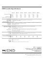
DDX models Specifications
Power Output Per Channel 8
4
2
Bridged Mono Power 8
4
DDX 1522
DDX 2022
DDX 2422
DDX 3222
DDX 3622
DDX 4022
DDX3842
280W
450W
750W
900W
1500W
350W
600W
1000W
1200W
2000W
450W
750W
1200W
1500W
2400W
550W
1000W
1600W
2000W
3200W
700W
1200W
1800W
2400W
3600W
850W
1600W
2000W
3200W
4000W
1100W
1900W
1500W
3800W
3000W
2.01V
2.19V
(EIA 1kHz - 1% THD both ch.s driven @ 230VAC)
Frequency Response
Distortion THD+N
Distortion SMPTE-IM
10Hz to 200Hz
Damping Factor @ 8
20Hz - 20kHz, +0 / -1dB
<0.2% @ 0.5dB below rated power @ 4, 1kHz; 0.4% @ 0.5dB below rated power @ 2, 1kHz,
<0.35% @ -3dB below rated power @ 8
>500 @ 8
(32dB Setting)
Input Sensitivity @ 4
Voltage Gain
Input Impedance
Hum and Noise
1.07V
1.23V
1.37V
1.59V
26dB (20x) or 32dB (40x) (internally set) 32dB is standard factory set
10k unbalanced, 20k balanced
-100dB,A-weighted
Input Connectors (each channel)
Output Connectors (each channel)
Controls
Led Indicators
Amplifier Protection
Load Protection
Circuitry
Power Supply
Cooling
Power Requirements
Current Draw (230VAC) 1/8 power 4
1/3 power 4
at idle
Options
Dimensions
Weight Net
Shipping
Approvals
1.74V
Balanced: Neutrik Combo™ (XLR and 1/4” jack), XLR pin 2 and TRS tip positive, and 3-pin detachable Europlug
Neutrik Speakon™
Front: power switch, Ch.A, Ch.B stepped gain knobs
Rear: 4-position DIP switch
Active status, signal -35dB, level -20dB, level -10dB, clip/limiter, protect, hi-temperature, internal option module expansion
Full short circuit, open circuit, thermal, ultrasonic and RF, continuous non-musical signals, reactive or mismatched loads,
mains AC outside the operating voltage
On / off muting, clip limiter, DC-fault power supply shutdown
TeoTon™ digital patented technology
Regulated global power supply (95 - 265VAC) works anywhere in the world with PFC (Power Factor Correction)
Continuously variable fans, front to rear air flow with front panel dust filter
95 - 265VAC, 50-60Hz
1.3A
1.5A
2.2A
2.7A
0.5A
0.5A
1.8A
3.3A
0.5A
2.2A
4.2A
0.5A
2.5A
5.0A
0.5A
3.2A
6.5A
0.5A
3.7A
7.6A
0.5A
DSP module for signal processing, WinARC™ Amplifier Remote Control by PC, dedicated and customized module for signal filter and equalisation
483mm W x 88mm H x 455mm D
10 kg
13 kg
CE EN55103-1 (Emissions), EN55103-2 (Immunity), EN60065, Class I (Safety)
KIND is a trademark of
A&AG S.r.l.
Via Montello, 19 - I-28066 Galliate (NO) ITALY
Tel. +39 0321/865271 - Fax +39 0321/861674
e-mail: [email protected]
www.kindaudio.com
In line with development policy specifications may change without future notice. We made our best to guarantee the information accuracy included on this publication, the
A&AG S.r.l. doesn’t undertake responsibility for mistakes or imprecisions.
V 1.2 © 2006 A&AG S.r.l.All rights reserved. Printed in Italy 02/06.