1
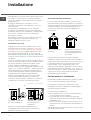
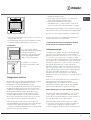
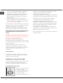
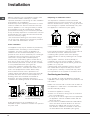
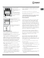
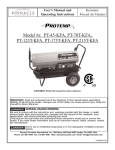
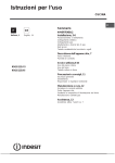
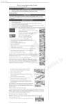
Istruzioni per l’uso
CUCINA
IT
IT
Italiano, 1
GB
English, 13
Sommario
Installazione, 2-5
Posizionamento e livellamento
Collegamento elettrico
Collegamento gas
Adattamento a diversi tipi di gas
Dati tecnici
Tabella caratteristiche bruciatori e ugelli
Descrizione dell’apparecchio, 6
Vista d’insieme
Pannello di controllo
Avvio e utilizzo,7-9
K1G11S/I
KN1G11S/I
Uso del piano cottura
Uso del forno
Tabella cottura in forno
Precauzioni e consigli, 10
Sicurezza generale
Smaltimento
Risparmiare e rispettare l’ambiente
Manutenzione e cura, 11
Escludere la corrente elettrica
Pulire l’apparecchio
Sostituire la lampadina di illuminazione del forno
Manutenzione rubinetti gas
Assistenza, 12
Assistenza attiva 7 giorni su 7
Installazione
IT
! È importante conservare questo libretto per poterlo
consultare in ogni momento. In caso di vendita, di
cessione o di trasloco, assicurarsi che resti insieme
all’apparecchio.
! Leggere attentamente le istruzioni: ci sono
importanti informazioni sull’installazione, sull’uso e
sulla sicurezza.
! L’installazione dell’apparecchio va effettuata
secondo queste istruzioni da personale qualificato.
! Qualsiasi intervento di regolazione o manutenzione
deve essere eseguito con la cucina disinserita
dall’impianto elettrico.
!Consigliamo di pulire il forno prima del suo primo
utilizzo seguendo le indicazioni riportate nel
paragrafo “Manutenzione e cura”.
Scarico dei fumi della combustione
Lo scarico dei fumi della combustione deve essere
assicurato tramite una cappa collegata a un camino a
tiraggio naturale di sicura efficienza, oppure mediante
un elettroventilatore che entri automaticamente in
funzione ogni volta che si accende l’apparecchio
(vedi figure).
Ventilazione dei locali
L’apparecchio può essere installato solo in locali
permanentemente ventilati, secondo le norme UNICIG 7129 e 7131 e successivi aggiornamenti in vigore.
Nel locale in cui viene installato l’apparecchio deve
poter affluire tanta aria quanta ne viene richiesta
dalla regolare combustione del gas (la portata di aria
non deve essere inferiore a 2 m3/h per kW di potenza
installata).
Le prese di immisione aria, protette da griglie, devono
avere un condotto di almeno 100 cm2 di sezione utile
ed essere collocate in modo da non poter essere
ostruite, neppure parzialmente (vedi figura A).
Tali prese devono essere maggiorate nella misura del
100% – con un minimo di 200 cm2 – qualora il piano di
lavoro dell’apparecchio sia privo del dispositivo di
sicurezza per assenza di fiamma e quando l’afflusso
dell’aria avviene in maniera indiretta da locali
adiacenti (vedi figura B) – purché non siano parti
comuni dell’immobile, ambienti con pericolo di
incendio o camere da letto – dotati di un condotto di
ventilazione con l’esterno come descritto sopra.
Locale adiacente
A
Locale da ventilare
B
A
Apertura di ventilazione
per l’aria comburente
Maggiorazione della
fessura fra porta e
pavimento
! Dopo un uso prolungato dell’apparecchio, è
consigliabile aprire una finestra o aumentare la
velocità di eventuali ventilatori.
2
Scarico direttamente
all’esterno
Scarico tramite camino o
canna fumaria ramificata
(riservata agli apparecchi
di cottura)
! I gas di petrolio liquefatti, più pesanti dell’aria,
ristagnano in basso, perciò i locali contenenti bidoni
di GPL devono prevedere aperture verso l’esterno per
l’evacuazione dal basso di eventuali fughe di gas.
I bidoni di GPL, vuoti o parzialmente pieni, non
devono essere installati o depositati in locali o vani a
livello più basso del suolo (cantinati, ecc.). Tenere nel
locale solo il bidone in utilizzo, lontano da sorgenti di
calore (forni, camini, stufe) capaci di portarlo a
temperature superiori ai 50°C.
Posizionamento e livellamento
! È possibile installare l’apparecchio di fianco a mobili
che non superino in altezza il piano di lavoro.
! Assicurarsi che la parete a contatto con il retro
dell’apparecchio sia di materiale non infiammabile e
resistente al calore (T 90°C).
Per una corretta installazione:
• porre l’apparecchio in cucina, in sala da pranzo o
in un monolocale (non in bagno);
• se il piano della cucina è più alto di quello dei
mobili, essi devono essere posti ad almeno 600 mm
dall’apparecchio;
• se la cucina viene installata sotto un pensile, esso
dovrà mantenere una distanza minima dal piano di
420 mm.
Tale distanza deve essere di 700 mm se i pensili sono
infiammabili (vedi figura);
420 mm.
420 mm.
Min.
600 mm.
Min.
Min.
min. 650 mm. with hood
min. 700 mm. without hood
HOOD
targhetta caratteristiche;
• la tensione di alimentazione sia compresa nei
valori nella targhetta caratteristiche;
• la presa sia compatibile con la spina
dell’apparecchio. In caso contrario sostituire la
presa o la spina; non usare prolunghe e multiple.
IT
! Ad apparecchio installato, il cavo elettrico e la presa
della corrente devono essere facilmente raggiungibili.
! Il cavo non deve subire piegature o compressioni.
• non posizionare tende dietro la cucina o a meno di
200 mm dai suoi lati;
• eventuali cappe devono essere installate secondo
le indicazioni del relativo libretto di istruzione.
! Il cavo deve essere controllato periodicamente e
sostituito solo da tecnici autorizzati.
! L’azienda declina ogni responsabilità qualora
queste norme non vengano rispettate.
Livellamento
Se è necessario livellare
l’apparecchio, avvitare i piedini
di regolazione forniti in
dotazione nelle apposite sedi
poste negli angoli alla base
della cucina (vedi figura).
Le gambe* si montano a
incastro sotto la base della
cucina.
Collegamento elettrico
Montare sul cavo una spina normalizzata per il carico
indicato nella targhetta caratteristiche posta
sull’apparecchio (vedi tabella Dati tecnici).
In caso di collegamento diretto alla rete è necessario
interporre tra l’apparecchio e la rete un interruttore
onnipolare con apertura minima fra i contatti di 3 mm,
dimensionato al carico e rispondente alle norme
nazionali in vigore (il filo di terra non deve essere
interrotto dall’interruttore). Il cavo di alimentazione
deve essere posizionato in modo tale che in nessun
punto superi di 50°C la temperatura ambiente.
Prima di effettuare l’allacciamento accertarsi che:
• la presa abbia la messa a terra e sia a norma di legge;
• la presa sia in grado di sopportare il carico
massimo di potenza della macchina, indicato della
*Presente solo su alcuni modelli.
Collegamento gas
Il collegamento alla rete del gas o alla bombola del
gas può essere effettuato con un tubo flessibile in
gomma o in acciaio, secondo le norme UNI-CIG 7129
e 7131 e successivi aggiornamenti in vigore e dopo
essersi accertati che l’apparecchio sia regolato per il
tipo di gas con cui sarà alimentato (vedi etichetta di
taratura sul coperchio: in caso contrario vedi sotto).
Nel caso di alimentazione con gas liquido da
bombola, utilizzare regolatori di pressione conformi
alle norme UNI EN 12864 e successivi aggiornamenti in
vigore. Per facilitare l’allacciamento, l’alimentazione
del gas è orientabile lateralmente*: invertire il
portagomma per il collegamento con il tappo di
chiusura e sostituire la guarnizione di tenuta fornita in
dotazione.
! Per un sicuro funzionamento, per un adeguato uso
dell’energia e per una maggiore durata
dell’apparecchio, assicurarsi che la pressione di
alimentazione rispetti i valori indicati nella tabella
Caratteristiche bruciatori e ugelli (vedi sotto).
Allacciamento gas con tubo flessibile in gomma
Verificare che il tubo risponda alle norme UNI-CIG
7140 in vigore. Il diametro interno del tubo deve
essere: 8 mm per alimentazione con gas liquido; 13
mm per alimentazione con gas metano.
Effettuato l’allacciamento assicurarsi che il tubo:
• non sia in nessun punto a contatto con parti che
raggiungono temperature superiori a 50°C;
• non sia soggetto ad alcuno sforzo di trazione e di
3
IT
torsione e non presenti pieghe o strozzature;
• non venga a contatto con corpi taglienti,
spigoli vivi, parti mobili e non sia schiacciato;
• sia facilmente ispezionabile lungo tutto il
percorso per poter controllare il suo stato di
conservazione;
• abbia una lunghezza inferiore a 1500 mm;
• sia ben calzato alle sue due estremità, dove va
fissato con fascette di serraggio conformi alle
norme UNI-CIG 7141 in vigore.
! Se una o più di queste condizioni non può essere
rispettata o se la cucina viene installata secondo le
condizioni della classe 2 - sottoclasse 1
(apparecchio incassato tra due mobili), bisogna
ricorrere al tubo flessibile in acciaio (vedi sotto).
Allacciamento gas con tubo flessibile in acciaio
inossidabile a parete continua con attacchi
filettati
Verificare che il tubo sia conforme alle norme UNICIG 9891 e le guarnizioni di tenuta metalliche in
alluminio conformi alla UNI 9001-2 o guarnizioni in
gomma conformi alla UNI EN 549.
Per mettere in opera il tubo eliminare il
portagomma presente sull’apparecchio (il raccordo
di entrata del gas all’apparecchio è filettato 1/2 gas
maschio cilindrico).
! Effettuare l’allacciamento in modo che la
lunghezza della tubatura non superi i 2 metri di
estensione massima, e assicurarsi che il tubo non
venga a contatto con parti mobili e non sia
schiacciato.
Controllo tenuta
A installazione ultimata, controllare la perfetta
tenuta di tutti i raccordi utilizzando una soluzione
saponosa e mai una fiamma.
Adattamento a diversi tipi di gas
È possibile adattare l’apparecchio a un tipo di gas
diverso da quello per il quale è predisposto
(indicato sull’etichetta di taratura sul coperchio).
Adattamento del piano cottura
Sostituzione degli ugelli dei
bruciatori del piano:
1. togliere le griglie e sfilare
i bruciatori dalle loro sedi;
2. svitare gli ugelli,
servendosi di una chiave a
4
tubo da 7 mm (vedi figura), e sostituirli con quelli
adatti al nuovo tipo di gas (vedi tabella
Caratteristiche bruciatori e ugelli);
3. rimettere in posizione tutti i componenti seguendo
le operazioni inverse rispetto alla sequenza di cui sopra.
Regolazione del minimo dei bruciatori del piano:
1. portare il rubinetto sulla posizione di minimo;
2. togliere la manopola e agire sulla vite di
regolazione posta all’interno o di fianco all’astina del
rubinetto fino a ottenere una piccola fiamma regolare.
! Nel caso di gas naturale, la vite di regolazione dovrà
essere svitata in senso antiorario;
3. verificare che, ruotando rapidamente il rubinetto
dalla posizione di massimo a quella di minimo, non si
abbiano spegnimenti del bruciatore.
! I bruciatori del piano non necessitano di regolazione
dell’aria primaria.
DATI TECNICI
IT
Dimensioni
Forno HxLxP
34x39,x38 cm
Volume
lt. 50
Assorbimento
max forno:
2000W
Tensione e
frequenza di
alimentazione
vedi targhetta caratteristiche
Bruciatori
adattabili a tutti i tipi di gas
indicati nella targhetta
caratteristiche.
Direttiva 2002/40/CE
sull’etichetta dei forni elettrici
Norma EN 50304
ENERGY LABEL
ConsuConsumo energia
dichiarazionemo energia
dichiarazione Classe
Convenzione Naturale
funzione di riscaldamento:
Statico
Direttive Comunitarie:
2006/95/EC del 12/12/06 (Bassa
Tensione) e successive
modificazioni - 2004/108/EC del
15/12/04 (Compatibilità
Elettromagnetica) e successive
modificazioni - 2009/142/EC del
29/06/90 (Gas) e successive
modificazioni -93/68/EC del
22/07/93 e successive
modificazioni - 2002/96/EC.
1275/2008 (Stand-by/ Off mode)
Tabella caratteristiche bruciatori e ugelli
!
"#
"#"
$
%
&
'(
)'
)&
(
)'(
*"#
*
%+
,
&
$
%
$'
$(
(
'
--
++
&
$
+
%$
%
%,
,+
)'$
)
$+
$%
)+
&+
)
%
)+
K1G11S/I
KN1G11S/I
S S
#
*
**
***
!.
/.
/0.
A 15°C e 1013 mbar- gas secco
Propano
P.C.S. = 50,37 MJ/Kg
Butano
P.C.S. = 49,47 MJ/Kg
Naturale
P.C.S. = 37,78 MJ/m3
A
R
5
Descrizione
dell’apparecchio
IT
Vista d’insieme
Coperchio in vetro*
Bruciatore a gas
Griglia del piano di lavoro
Piano di contenimento
per eventuali trabocchi
Pannello di controllo
GUIDE
di scorrimento dei ripiani
posizione 5
posizione 4
posizione 3
posizione 2
posizione 1
Ripiano GRIGLIA
Ripiano LECCARDA
Piedino di regolazione
Piedino di regolazione
Pannello di controllo
La spia termostato forno
Manopola del termostato
Manopola di selezione
La manopola del contaminuti
Manopole dei bruciatori
del piano di cottura
La spia termostato forno
Manopola del termostato
Manopola di selezione
La manopola del contaminuti
Manopole dei bruciatori
del piano di cottura
ATTENZIONE! Il coperchio in vetro
può frantumarsi se viene riscaldato.
Spegnere tutti i bruciatori o le eventuali piastre elettriche prima di
chiuderlo.*Solo per i modelli con co-
* Presente solo su alcuni modelli.
6
perchio vetro.
Avvio e utilizzo
Uso del piano cottura
ruiatore
Accensione dei bruciatori
In corrispondenza di ogni manopola BRUCIATORE è
indicato con un cerchietto pieno il bruciatore
associato.
Per accendere un bruciatore del piano cottura:
1. avvicinare al bruciatore una fiamma o un
accendigas;
2. premere e contemporaneamente ruotare in senso
antiorario la manopola BRUCIATORE sul simbolo di
fiamma massima E.
3. regolare la potenza della fiamma desiderata,
ruotando in senso antiorario la manopola
BRUCIATORE: sul minimo C, sul massimo E o su una
posizione intermedia.
Se l’apparecchio è dotato di
accensione elettronica* (C),
prima premere il pulsante di
accensione, identificato dal
X
simbolo
1, poi premere a
fondo e
contemporaneamente
ruotare in senso antiorario la manopola
BRUCIATORE sul simbolo di fiamma massima, fino
ad accensione avvenuta. Può accadere che il
bruciatore si spenga al momento del rilascio della
manopola. In questo caso, ripetere l’operazione
tenendo premuta la manopola più a lungo.
C
! In caso di estinzione accidentale delle fiamme,
spegnere il bruciatore e aspettare almeno 1 minuto
prima di ritentare l’accensione.
Se l’apparecchio è dotato di dispositivo di
sicurezza* (X) per assenza di fiamma, tenere
premuta la manopola BRUCIATORE circa 2-3
secondi per mantenere accesa la fiamma e per
attivare il dispositivo.
Per spegnere il bruciatore ruotare la manopola fino
all’arresto •.
Consigli pratici per l’uso dei bruciatori
IT
iaetroreiieti
Rapido(R)
24@26
SemiRapido(S)
16@20
Ausiliario(A)
10@14
Per identificare il tipo di bruciatore fate riferimento ai
disegni presenti nel paragrafo "Caratteristiche dei
bruciatori ed ugelli".
! Sui modelli dotati di griglietta di riduzione,
quest’ultima dovrà essere utilizzata solo per il
bruciatore ausiliario, quando si utilizzano dei
recipienti di diametro inferiore a 12 cm.
Al fine di ottenere il massimo rendimento è utile
ricordare quanto segue:
• utilizzare recipienti adeguati a ciascun bruciatore
(vedere tabella) alfine di evitare che le fiamme
fuoriescano dal fondo dei recipienti.
• utilizzare solamente recipienti a fondo piatto.
• al momento dell’ebollizione ruotare la manopola
fino alla posizione di minimo.
• utilizzare sempre recipienti con coperchio.
Le manopole del forno
Tramite questi due comandi è possibile selezionare
le diverse funzioni del forno e scegliere la
temperatura di cottura più idonea ai cibi da cuocere.
La selezione delle diverse funzioni di cottura si
ottiene agendo sulle due manopole:
di selezione
del termostato presenti sul cruscotto.
Per qualsiasi posizione della manopola di selezione,
o”,
diversa da quella di riposo contrassegnata dallo “o
si ha l’accensione della luce forno; la posizione della
manopola contrassegnata dal simbolo 8 permette
di accendere la luce del forno senza che alcun
elemento riscaldante sia attivato.
L’accensione della luce del forno sta ad indicare che
il forno è in funzione, rimane sempre accesa durante
la cottura.
Per un miglior rendimento dei bruciatori e un consumo
minimo di gas occorre usare recipienti a fondo piatto,
provvisti di coperchio e proporzionati al bruciatore:
* Presente solo su alcuni modelli.
7
IT
Attenzione: Alla prima accensione consigliamo di
far funzionare il forno a vuoto per circa mezz’ora con
il termostato al massimo e a porta chiusa. Quindi
trascorso tale tempo spegnerlo, aprite la porta ed
areare il locale. L’odore che talvolta si avverte
durante questa operazione è dovuto all’evaporazione
delle sostanze usate per proteggere il forno durante
l’intervallo di tempo che intercorre tra la produzione
e l’installazione del prodotto.
Attenzione: Utilizzare il primo ripiano dal basso
solamente nel caso di cotture con grill. Per le altre
cotture non utilizzate mai il primo ripiano dal basso e
non appoggiate mai oggetti sul fondo del forno
mentre state cuocendo perchè potreste causare
danni allo smalto. Ponete sempre i Vostri recipienti
di cottura (pirofile, pellicole di alluminio, ecc. ecc.)
sulla griglia in dotazione con l’apparecchio
appositamente inserita nelle guide del forno.
Forno Statico
Posizione manopola termostatora 50
50°C e Max
Max.
In questa posizione si accendono i due elementi
riscaldanti inferiore e superiore. E’ il classico forno
della nonna che è stato però portato ad un
eccezionale livello di distribuzione della temperatura
e di contenimento dei consumi. Il forno statico resta
insuperato nei casi in cui si debbano cucinare piatti i
cui ingredienti risultano composti da due o più
elementi che concorrono a formare un piatto unico
come ad esempio: cavoli con costine di maiale,
baccalà alla spagnola, stoccafisso all’anconetana,
teneroni di vitello con riso etc... Ottimi risultati si
ottengono nella preparazione di piatti a base di carni
di manzo o vitello quali: brasati, spezzatini, gulasch,
carni di selvaggina, cosciotto e lombo di maiale
etc... che necessitano di cottura lenta con costante
aggiunta di liquidi. Resta comunque il miglior
sistema di cottura per i dolci, per la frutta e per le
cotture con recipienti coperti specifici per le cotture
al forno. Nella cottura al forno statico utilizzate un
solo ripiano, in quanto su più ripiani si avrebbe una
cattiva distribuzione della temperatura. Usando i
diversi ripiani a disposizione potrete bilanciare la
quantità di calore tra la parte superiore ed inferiore.
Se la cottura necessita di maggior calore dal basso
o dall’alto, utilizzate rispettivamente i ripiani inferiori
o superiori.
Forno Dolce
Posizione manopola termostato tra 50
50°C e Max
Max.
Si accende l’elemento riscaldante inferiore.
Questa funzione è indicata per la cottura di cibi
delicati, in particolare i dolci che necessitano di
8
lievitazione, in quanto viene facilitata dal calore
proveniente dal basso.
Viene fatto notare che le temperature più elevate
vengono raggiunte in tempi piuttosto lunghi,
pertanto in questi casi è consigliabile utilizzare la
funzione “Forno Statico”.
Forno “sopra”
Posizione manopola termostato tra 50
50°C e Max
Max.
Si accende l’elemento riscaldante superiore.
Questa funzione può essere utilizzata per ritocchi di
cottura.
Grill
Posizione manopola termostato Max
Max.
Si accende l’elemento riscaldante superiore centrale.
La temperatura assai elevata e diretta del grill
consente la immediata rosolatura superficiale dei
cibi che, ostacolando la fuoriuscita dei liquidi, li
mantiene più teneri internamente. La cottura al grill è
particolarmente consigliata per quei piatti che
necessitano di elevata temperatura superficiale:
bistecche di vitello e manzo, entrecôte, filetto,
hamburger etc...
Alcuni esempi di utilizzo sono riportati al paragrafo
“Consigli pratici per la cottura”.
Il contaminuti
Per utilizzare il contaminuti occorre caricare la
suoneria ruotando la manopola di un giro quasi
completo in senso orario 4 quindi, tornando indietro
5, , impostare il tempo desiderato facendo
coincidere con il riferimento fisso del frontalino il
numero corrispondente ai minuti prefissati.
La spia termostato forno
Indica la fase di riscaldamento dello stesso, il suo
spegnimento segnala il raggiungimento all’interno
del forno della temperatura impostata con la
manopola. A questo punto l’alternativo accendersi e
spegnersi di questa spia indica che il termostato sta
lavorando correttamente per mantenere costante la
temperatura del forno.
Vano inferiore (presente solo su alcuni modelli)
IT
Sotto il forno è presente un
vano che può essere
utilizzato per il deposito di
accessori o casseruole. Per
aprire lo sportello è
necessario farlo ruotare
verso il basso.
Attenzione: non utilizzare
mai il vano per il deposito
di materiale infiammabile.
Tabella cottura in forno
osiioe
aoola
seleioe
1#tatio
ibodauiare
Anatra
ArrostodiDitelloomanzo
Arrostodimaiale
Biscotti(diErolla)
Frostate
Gasagne
Agnello
Sgombro
Plum-cake
BignH
Pandispagna
Iortesalate
$%oroole IortelieDitate
Frostate
IortediErutta
Brioches
&%oro#ora Ritocchidicottura
'Grill
Soglioleeseppie
Spiedinidicalamarie
gamberi
Oilettodimerluzzo
Qerdureallagriglia
BisteccadiDitello
Fotolette
Ramburger
Sgombri
Ioast
eso osiioedi
! otturariiai
dalbasso
Teodire"
risaldaeto
iuti
osiioe
aoola
terostato
Teodi
ottura
iuti
1
3
15
200
65-75
1
1
1
1
1
1
1
0.3
0.5
1.5
3
3
3
3
3
2
2
2
3
3
3
15
15
15
15
10
10
10
10
10
10
15
200
200
180
180
190
180
180
170
180
170
200
70-75
70-80
15-20
30-35
35-40
50-60
30-35
40-50
30-35
20-25
30-35
0L5
1
1
0L5
3
3
3
3
15
15
15
15
160
180
180
160
30-40
35-40
50-60
25-30
-
3/4
15
220
-
1
4
5
Max
8-10
1
1
1
1
1
1
1
n.T4
4
4
3/4
4
4
4
4
4
5
5
5
5
5
5
5
5
Max
Max
Max
Max
Max
Max
Max
Max
6-8
10
10-15
15-20
15-20
7-10
15-20
2-3
N(itempidicotturasonoindicatiDiepossonoesseremodiEicatiinbaseaiproprigustipersonali.Nellecottureal
grilllaleccardaDapostasempreal1Tripianoapartiredalbasso.
9
Precauzioni e consigli
IT
! L’apparecchio è stato progettato e costruito in
conformità alle norme internazionali di sicurezza.
Queste avvertenze sono fornite per ragioni di
sicurezza e devono essere lette attentamente.
Sicurezza generale
• L’apparecchio è stato concepito per un uso di tipo
non professionale all’interno dell’abitazione.
• L’apparecchio non va installato all’aperto,
nemmeno se lo spazio è riparato, perché è molto
pericoloso lasciarlo esposto a pioggia e temporali.
• Non toccare la macchina a piedi nudi o con le
mani
o con i piedi bagnati o umidi.
• L’apparecchio deve essere usato per cuocere
alimenti, solo da persone adulte e secondo le
istruzioni riportate in questo libretto. Ogni
altro uso (ad esempio: riscaldamento di
ambienti) è da considerarsi improprio e quindi
pericoloso. Il costruttore non può essere
considerato responsabile per eventuali danni
derivanti da usi impropri, erronei ed
irragionevoli.
• Il libretto riguarda un apparecchio di classe 1
(isolato) o classe 2 – sottoclasse 1 (incassato tra
due mobili).
• Durante l'uso dell'apparecchio gli elementi
riscaldanti e alcune parti della porta forno
diventano molto calde. Fare attenzione a non
toccarle e tenere i bambimi a distanza.
• Evitare che il cavo di alimentazione di altri
elettrodomestici entri in contatto con parti calde
dell’apparecchio.
• Non ostruire le aperture di ventilazione e di
smaltimento di calore.
• Utilizzare sempre guanti da forno per inserire
o estrarre recipienti.
• Non utilizzare liquidi infiammabili (alcol, benzina,
ecc.) in prossimità dell’apparecchio quando esso
è in uso.
• Non riporre materiale infiammabile nel vano
inferiore di deposito o nel forno: se l’apparecchio
viene messo inavvertitamente in funzione potrebbe
incendiarsi.
• Le superfici interne del cassetto (se presente)
possono diventare calde.
• Quando l’apparecchio non è utilizzato, assicurarsi
sempre che le manopole siano nella posizione •.
• Non staccare la spina dalla presa della corrente
tirando il cavo, bensì afferrando la spina.
• Non fare pulizia o manutenzione senza aver prima
staccato la spina dalla rete elettrica.
10
• In caso di guasto, in nessun caso accedere ai
meccanismi interni per tentare una riparazione.
Contattare l’Assistenza.
• Non appoggiare oggetti pesanti sulla porta
del forno aperta.
• Evitare che i bambini giochino con l'apparecchio.
• Non è previsto che l'apparecchio venga utilizzato
da persone (bambini compresi) con ridotte
capacità fisiche, sensoriali o mentali, da persone
inesperte o che non abbiano familiarità con il
prodotto, a meno che non vengano sorvegliate da
una persona responsabile della loro sicurezza o
non abbiano ricevuto istruzioni preliminari sull'uso
dell'apparecchio.
Smaltimento
• Smaltimento del materiale di imballaggio:
attenersi alle norme locali, così gli imballaggi
potranno
essere riutilizzati.
• La direttiva Europea 2002/96/CE sui rifiuti di
apparecchiature elettriche ed elettroniche (RAEE),
prevede che gli elettrodomestici non debbano
essere smaltiti nel normale flusso dei rifiuti solidi
urbani. Gli apparecchi dismessi devono essere
raccolti separatamente per ottimizzare il tasso di
recupero e riciclaggio dei materiali che li
compongono ed impedire potenziali danni per la
salute e l’ambiente. Il simbolo del cestino barrato è
riportato su tutti i prodotti per ricordare gli obblighi
di raccolta separata.
Per ulteriori informazioni, sulla corretta dismissione
degli elettrodomestici, i detentori potranno
rivolgersi al servizio pubblico preposto o ai
rivenditori.
Risparmiare e rispettare l’ambiente
• Azionando il forno negli orari che vanno dal tardo
pomeriggio fino alle prime ore del mattino si
collabora a ridurre il carico di assorbimento delle
aziende elettriche.
• Si raccomanda di effettuare sempre le cotture
GRILL a porta chiusa: sia per ottenere migliori
risultati che per un sensibile risparmio di energia
(10% circa).
• Mantenere efficienti e pulite le guarnizioni, in
modo che aderiscano bene alla porta e non
procurino
dispersioni di calore.
Manutenzione e cura
Escludere la corrente elettrica
Controllare le guarnizioni del forno
Prima di ogni operazione isolare l’apparecchio dalla
rete di alimentazione elettrica.
Controllare periodicamente lo stato della guarnizione
attorno alla porta del forno. In caso risulti danneggiata
rivolgersi al Centro Assistenza Autorizzato più vicino.
È consigliabile non usare il forno fino all’avvenuta
riparazione.
Pulire l’apparecchio
! Non utilizzare mai pulitori a vapore o ad alta
pressione per la pulizia dell’apparecchio.
• Le parti esterne smaltate o inox e le guarnizioni in
gomma possono essere pulite con una spugnetta
imbevuta di acqua tiepida e sapone neutro. Se le
macchie sono difficili da asportare usare prodotti
specifici. Sciacquare abbondantemente e
asciugare dopo la pulizia. Non usare polveri
abrasive o sostanze corrosive.
• Le griglie, i cappellotti, le corone spartifiamma
e i bruciatori del piano cottura sono estraibili
per facilitare la pulizia; lavarli in acqua calda e
detersivo non abrasivo, avendo cura di togliere
ogni incrostazione e attendere che siano
perfettamente asciutti.
• Pulire frequentemente la parte terminale dei
dispositivi di sicurezza* per assenza di fiamma.
• L’interno del forno va pulito preferibilmente ogni
volta dopo l’uso, quando è ancora tiepido. Usare
acqua calda e detersivo, risciaquare e asciugare
con un panno morbido. Evitare gli abrasivi.
• Pulire il vetro della porta con spugne e prodotti non
abrasivi e asciugare con un panno morbido; non
usare materiali ruvidi abrasivi o raschietti metallici
affilati che possono graffiare la superficie e causare
la frantumazione del vetro.
• Gli accessori possono essere lavati come normali
stoviglie, anche in lavastoviglie.
Sostituire la lampadina di illuminazione
del forno
1. Dopo aver disinserito il forno
dalla rete elettrica, togliere il
coperchio in vetro del
portalampada (vedi figura).
2. Svitare la lampadina e
sostituirla con una analoga:
tensione 230V, potenza 25 W,
attacco E 14.
3. Rimontare il coperchio e ricollegare il forno alla rete
elettrica.
Manutenzione rubinetti gas
Con il tempo può verificarsi il caso di un rubinetto che
si blocchi o presenti difficoltà nella rotazione, pertanto
sarà necessario provvedere alla sostituzione del
rubinetto stesso.
! Questa operazione deve essere effettuata da un
tecnico autorizzato dal costruttore.
Estrazione del coperchio
Il coperchio della cucina può
essere rimosso per facilitarne la
pulizia. Per rimuovere il
coperchio, è necessario aprirlo
completamente e tirare verso
l’alto (vedi figura)
• Evitare di chiudere il coperchio quando i bruciatori
sono accesi o sono ancora caldi.
* Presente solo su alcuni modelli.
11
IT
Assistenza
! Non ricorrere mai a tecnici non autorizzati.
IT
Comunicare:
• Il tipo di anomalia;
• Il modello della macchina (Mod.)
• Il numero di serie (S/N)
Queste ultime informazioni si trovano sulla targhetta caratteristiche posta sull’apparecchio
Assistenza attiva 7 giorni su 7
In caso di necessità d’intervento chiamare il Numero Unico Nazionale 199.199.199*.
Un operatore sarà a completa disposizione per fissare un appuntamento con il Centro Assistenza Tecnico
Autorizzato più vicino al luogo da cui si chiama.
È attivo 7 giorni su 7, sabato e domenica compresi, e non lascia mai inascoltata una richiesta.
*Al costo di 14,26 centesimi di Euro al minuto(iva inclusa) dal Lun. al Ven. dalle 08:00 alle 18:30, il Sab. dalle 08:00 alle
13:00 e di 5,58 centesimi di Euro al minuto (iva inclusa) dal Lun. al Ven. dalle 18:30 alle 08:00, il Sab. dalle 13:00 alle
08:00 e i giorni festivi, per chi chiama da telefono fisso.
Per chi chiama da radiomobile le tariffe sono legate al piano tariffario dell’operatore telefonico utilizzato.
Le suddette tariffe potrebbero essere soggette a variazione da parte dell’operatore telefonico; per maggiori informazioni
consultare il sito www.aristonchannel.com.
12
Operating Instructions
COOKER
GB
IT
Italiano, 1
GB
Contents
Installation, 14-17
English,13
Positioning and levelling
Electrical connection
Gas connection
Adapting to different types of gas
Technical data
Table of burner and nozzle specifications
Description of the appliance, 18
Overall view
Control panel
Start-up and use, 19-21
K1G11S/I
KN1G11S/I
Using the hob
Using the oven
Oven cooking advice table
Precautions and tips, 22
General safety
Disposal
Respecting and conserving the environment
Care and maintenance, 23
Switching the appliance off
Cleaning the appliance
Replacing the oven light bulb
Gas tap maintenance
Assistance
Installation
GB
! Before operating your new appliance please read
this instruction booklet carefully. It contains
important information concerning the safe installation
and operation of the appliance.
! Please keep these operating instructions for future
reference. Make sure that the instructions are kept
with the appliance if it is sold, given away or moved.
! The appliance must be installed by a qualified
professional according to the instructions provided.
! Any necessary adjustment or maintenance must be
performed after the cooker has been disconnected
from the electricity supply.
! We recommend cleaning the oven before using it
for the first time, following the instructions provided
in the "Care and maintenance" section.
Disposing of combustion fumes
Room ventilation
Fumes channelled
straight outside
The appliance may only be installed in permanentlyventilated rooms, according to current national
legislation. The room in which the appliance is
installed must be ventilated adequately so as to
provide as much air as is needed by the normal gas
combustion process (the flow of air must not be
lower than 2 m3/h per kW of installed power).
The air inlets, protected by grilles, should have a
duct with an inner cross section of at least 100 cm2
and should be positioned so that they are not liable
to even partial obstruction (see figure A).
These inlets should be enlarged by 100% - with a
minimum of 200 cm2 - whenever the surface of the
hob is not equipped with a flame failure safety
device. When the flow of air is provided in an
indirect manner from adjacent rooms (see figure B),
provided that these are not communal parts of a
building, areas with increased fire hazards or
bedrooms, the inlets should be fitted with a
ventilation duct leading outside as described above.
A
The disposal of combustion fumes should be
guaranteed using a hood connected to a safe and
efficient natural suction chimney, or using an electric
fan that begins to operate automatically every time
the appliance is switched on (see figure).
Fumes channelled through
a chimney or branched
flue system reserved for
cooking appliances)
! The liquefied petroleum gases are heavier than air
and collect by the floor, therefore all rooms
containing LPG cylinders must have openings
leading outside so that any leaked gas can escape
easily.
LPG cylinders, therefore, whether partially or
completely full, must not be installed or stored in
rooms or storage areas that are below ground level
(cellars, etc.). Only the
cylinder being used should be stored in the room;
this should also be kept well away from sources
of heat (ovens, chimneys, stoves) that may cause
the temperature of the cylinder to rise above 50°C.
Positioning and levelling
! It is possible to install the appliance alongside
cupboards whose height does not exceed that of the
hob surface.
B
! Make sure that the wall in contact with the back of
the appliance is made from a non-flammable, heatresistant material (T 90°C).
A
Ventilation opening for
comburent air
Increase in the gap between
the door and the flooring
! After prolonged use of the appliance, it is
advisable to open a window or increase the speed of
any fans used.
14
To install the appliance correctly:
• Place it in the kitchen, dining room or the bed-sit
(not in the bathroom).
• If the top of the hob is higher than the cupboards,
the appliance must be installed at least 200 mm
away from them.
• If the cooker is installed underneath a wall cabinet,
there must be a minimum distance of 420 mm
between this cabinet and the top of the hob.
This distance should be increased to 700 mm if
the wall cabinets are flammable (see figure).
420 mm.
420 mm.
Min.
600 mm.
Min.
Min.
min. 650 mm. with hood
min. 700 mm. without hood
HOOD
• Do not position
blinds behind the
cooker or less than 200
mm away from its
sides.
• Any hoods must be
installed according to
the instructions listed in
the relevant operating
manual.
Levelling
If it is necessary to level the
appliance, screw the
adjustable feet into the places
provided on each corner of the
base of the cooker (see
figure).
The legs* fit into the slots on
the underside of the base of
the cooker.
Electrical connection
Install a standardised plug corresponding to the
load indicated on the appliance data plate (see
Technical data table).
The appliance must be directly connected to the mains
using an omnipolar circuit-breaker with a minimum
contact opening of 3 mm installed between the
appliance and the mains. The circuit-breaker must be
suitable for the charge indicated and must comply with
NFC 15-100 regulations (the earthing wire must not be
interrupted by the circuit-breaker). The supply cable
must be positioned so that it does not come into
contact with temperatures higher than 50°C at any point.
Before connecting the appliance to the power
supply, make sure that:
• The appliance is earthed and the plug is compliant
with the law.
• The socket can withstand the maximum power of
the appliance, which is indicated by the data plate.
• The voltage is in the range between the values
indicated on the data plate.
• The socket is compatible with the plug of the
appliance. If the socket is incompatible with the
plug, ask an authorised technician to replace it.
Do not use extension cords or multiple sockets.
* Only available in certain models
! Once the appliance has been installed, the power
supply cable and the electrical socket must be
easily accessible.
! The cable must not be bent or compressed.
! The cable must be checked regularly and replaced
by authorised technicians only.
! The manufacturer declines any liability should
these safety measures not be observed.
Gas connection
Connection to the gas network or to the gas cylinder
may be carried out using a flexible rubber or steel
hose, in accordance with current national legislation
and after making sure that the appliance is suited to
the type of gas with which it will be supplied (see the
rating sticker on the cover: if this is not the case see
below). When using liquid gas from a cylinder, install a
pressure regulator which complies with current national
regulations. To make connection easier, the gas
supply may be turned sideways*: reverse the position
of the hose holder with that of the cap and replace the
gasket that is supplied with the appliance.
! Check that the pressure of the gas supply is
consistent with the values indicated in the Table of
burner and nozzle specifications (see below). This
will ensure the safe operation and durability of your
appliance while maintaining efficient energy
consumption.
Gas connection using a flexible rubber hose
Make sure that the hose complies with current
national legislation. The internal diameter of the hose
must measure: 8 mm for liquid gas supply; 13 mm
for methane gas supply.
Once the connection has been performed, make
sure that the hose:
• Does not come into contact with any parts that
reach temperatures of over 50°C.
• Is not subject to any pulling or twisting forces and
that it is not kinked or bent.
• Does not come into contact with blades, sharp
corners or moving parts and that it is not
compressed.
• Is easy to inspect along its whole length so that
its condition may be checked.
• Is shorter than 1500 mm.
• Fits firmly into place at both ends, where it will be
fixed using clamps that comply with current
regulations.
15
GB
GB
! If one or more of these conditions is not fulfilled or
if the cooker must be installed according to the
conditions listed for class 2 - subclass 1 appliances
(installed between two cupboards), the flexible steel
hose must be used instead (see below).
3. While the burner is alight, quickly change the position
of the knob from minimum to maximum and vice versa
several times, checking that the flame is not
extinguished.
! The hob burners do not require primary air adjustment.
Connecting a flexible jointless stainless steel pipe
to a threaded attachment
Adjusting the gas oven burner’s minimum setting:
Make sure that the hose and gaskets comply with
current national legislation.
To begin using the hose, remove the hose holder on the
appliance (the gas supply inlet on the appliance is a
cylindrical threaded 1/2 gas male attachment).
! Perform the connection in such a way that the hose
length does not exceed a maximum of 2 metres,
making sure that the hose is not compressed and
does not come into contact with moving parts.
Checking the connection for leaks
When the installation process is complete, check
the hose fittings for leaks using a soapy solution.
Never use a flame.
Adapting to different types of gas
It is possible to adapt the appliance to a type of gas
other than the default type (this is indicated on the
rating label on the cover).
Adapting the hob
Replacing the nozzles for the hob burners:
1. Remove the hob grids and slide the burners off
their seats.
2. Unscrew the nozzles using a
7 mm socket spanner (see
figure), and replace them with
nozzles suited to the new type
of gas(see Burner and nozzle
specifications table).
3. Replace all the components
by following the above
instructions in reverse.
Adjusting the hob burners’ minimum setting:
1. Turn the tap to the minimum position.
2. Remove the knob and adjust the regulatory
screw, which is positioned inside or next to the tap
pin, until the flame is small but steady.
! If the appliance is connected to a liquid gas
supply, the regulatory screw must be fastened as
tightly as possible.
16
1. Light the burner (see Start-up and Use).
2. Turn the knob to the minimum position (MIN) after
it has been in the maximum position (MAX) for
approximately 10 minutes.
3. Remove the knob.
4. Tighten or loosen the adjustment screws on the
outside of the thermostat pin (see figure) until the
flame is small but steady.
! If the appliance is connected to liquid gas, the
adjustment screw must be fastened as tightly as
possible.
T E C H N IC A L D A T A
O v e n D im e n s io n s
H xW xD
3 4x3 9 x3 8 c m
V o lu m e
50 l
M a x im u m
a b s o rb e r p o we r
2 00 0 W
GB
D ire c tive 2 00 2 /4 0/E C o n th e lab e l
o f e le c tric o ven s N orm E N 50 3 04
E n e rg y L a b e l
E n erg y c on su m p tio n C la ss
c ertifica tio n N a tu ra l co n ve c tio n
h ea tin g m o d e : S ta tic
V o lta g e a n d
fre q u e n c y
s ee d a ta p la te
B u rn e rs
a d ap tab le for u se w ith a ll th e typ e s
o f g a s ind ic a te d o n th e d ata p la te
situa te d insid e th e flap o r, on c e th e
d is hw arm e r d raw er h a s b e en
o p en e d , on th e in sid e w a ll of th e
le ft-h an d sid e p a ne l
E C D ire c tive s 20 0 6/9 5 /E C d a ted
1 2/1 2 /0 6 (L o w V olta g e ) an d
sub se q ue n t am en d m en ts 0 4/1 0 8 /E C d ate d 1 5/1 2 /0 4
(E le c trom a g ne tic C om p a tib ility)
a nd su b se q u en t a m e nd m e nts 2 00 9 /1 42 /E C d a te d 3 0 /1 1/0 9 (Ga s)
a nd su b se q u en t a m e nd m e nts 9 0/6 8 /E E C d a ted 2 2 /07 /9 3 a n d
sub se q ue n t am en d m en ts. 2 00 2 /9 6/E C .
1 27 5 /2 00 8 (S ta nd -b y/Off-m o d e)
!""
#
$
!""
!
%&&
#
#
'$%
(
)
+
26
:2
:+
6
:26
;#
<&;
)>
?
+
(
)
(2
(6
6
2
@D
;@
>>
+
(
>
)(
)
)?
?>
:2(
:
(>
()
:>
+>
;
*
**
***
!E
<E
<DE
At 15°C and 1013 mbar- dry gas
Propane
P.C.S. = 50,37 MJ/Kg
Butane
P.C.S. = 49,47 MJ/Kg
Natural
P.C.S. = 37,78 MJ/m3
K1G11S/I
KN1G11S/I
:
)
:>
S S
A
R
17
Description of the
appliance
GB
Overall view
Glass cover*
Gas burner
Containment
surface for spills
Hob grid
GUIDE RAILS
for the sliding racks
position 5
position 4
position 3
position 2
position 1
Control panel
GRILL rack
DRIPPING PAN
Adjustable foot
Adjustable foot
Control panel
Timer Knob
Thermostat knob
Timer Knob
Thermostat knob
* Only available in certain models.
18
The oven-operating pilot lamp
Selection knob
Control Knobs for Gas Burners on Hob
The oven-operating pilot lamp
Selection knob
Control Knobs for Gas Burners on Hob
WARNING! The glass lid can
break in if it is heated up.
Turn off all the burners and
the electric plates before
closing the lid. *Applies to the
models with glass cover only.
Start-up and use
etc. etc.) on the grate provided with the appliance
inserted especially along the oven guides.
Using the hob
Lighting the burners
GB
The oven knobs
For each BURNER knob there is a complete ring
showing the strength of the flame for the relevant
burner.
To light one of the burners on the hob:
1. Bring a flame or gas lighter close to the burner.
2. Press the BURNER knob and turn it in an
anticlockwise direction so that it is pointing to the
maximum flame setting E.
3. Adjust the intensity of the flame to the desired
level by turning the BURNER knob in an
anticlockwise direction. This may be the minimum
setting C, the maximum setting E or any position in
between the two.
To obtain these settings, turn the knob counterclockwise with respect to the off position. To turn off
the burner, turn the knob clockwise until it stops
(corresponding again with the • symbol).
With these two controls you can select the different
functions of the oven and choose the cooking
temperature suitable for the food you are preparing.
The different cooking functions are set up by
operating the two knobs:
the selection knob
the thermostat knob in the oven panel.
For any selection-knob setting different from idle,
0”, the oven light turns on; the
identified by the “0
knob setting marked 8 permits turning on the oven
light without any heating element being switched on.
When the oven light is on, it means that the oven is
in use, and it will remain on for the entire time the
oven is being used.
Practical advice on using the burners
Models with Hob Gas Burner Safety Devices to
Prevent Leaks
These models can be
identified by the presence of
the device itself (see detail
X ).
X
Important: Since the hob
burners are equipped with a
safety device, you must hold the control knob in for
about 6 seconds after the burner has been lighted to
allow the gas to pass until the safety thermocouple
has heated.
C
Notice: The first time you use your appliance, we
recommend that you set the thermostat to the
highest setting and leave the oven on for about half
an hour with nothing in it, with the oven door shut.
Then, open the oven door and let the room air. The
odour that is often detected during this initial use is
due to the evaporation of substances used to
protect the oven during storage and until it is
installed.
Attention: Only use the bottom shelf of the oven
when using the grill to cook. For all other types of
cooking, never use the bottom shelf and never place
anything on the bottom of the oven when it is in
operation because this could damage the enamel.
Always place your cookware (dishes, aluminium foil,
For the burners to work in the most efficient way
possible and to save on the amount of gas
consumed, it is recommended that only pans that
have a lid and a flat base are used. They should also
be suited to the size of the burner.
urer
arediaeter
Fast(R)
24-26
SemiFast(S)
16-20
Auxiliary(A)
10-14
To identify the type of burner, please refer to the
diagrams contained in the “Burner and nozzle
specifications”.
Practical advice for burner use
In order to get the maximum yield it is important to
remember the following:
· Use appropriate cookware for each burner (see
table) so as to avoid flames overshooting the
edges.
· At boiling point turn the knob to minimum.
· Use cookware with lids.
· Always use cookware with flat bottoms.
19
GB
Convection Mode
Grill
Position of thermostat knob between 50
50°C and
Max.
On this setting, the top and bottom heating
elements come on. This is the classic, traditional
type of oven which has been perfected, with
exceptional heat distribution and reduced energy
consumption. The convection oven is still
unequalled when it comes to cooking dishes made
up of several ingredients, e.g. cabbage with ribs,
Spanish style cod, Ancona style stockfish, tender
veal strips with rice, etc. Excellent results are
achieved when preparing veal or beef-based dishes
as well (braised meats, stew, goulash, wild game,
ham etc.) which need to cook slowly and require
basting or the addition of liquid. It nonetheless
remains the best system for baking cakes as well
as fruit and cooking using covered casserole dishes
for oven baking. When cooking in convection mode,
only use one dripping pan or cooking rack at a time,
otherwise the heat distribution will be uneven. Using
the different rack heights available, you can balance
the amount of heat between the top and the bottom
of the oven. Select from among the various rack
heights based on whether the dish needs more or
less heat from the top.
Pastry Mode
Position of thermostat knob between 50
50°C and
Max.
The bottom heating element comes on.
This mode is ideal for baking and cooking delicate
foods - especially cakes that need to rise because
the heat coming from the bottom helps the
leavening process.
Please note that it takes a considerable amount of
time for the higher temperatures to be reached,
therefore we recommend you use the “Convection
Mode” in these cases.
“Top” Oven
Position of thermostat knob between 50
50°C and
Max.
The top heating element comes on.
This mode can be used to brown food at the end of
cooking.
*Available only in certain models
20
Position of thermostat knob: Max
The top central heating element comes on.
The extremely high and direct temperature of the
grill makes it possible to brown the surface of meats
and roasts while locking in the juices to keep them
tender. The grill is also highly recommended for
dishes that require a high temperature on the
surface: beef steaks, veal, rib steak, filets,
hamburgers etc...
Some grilling examples are included in the “Practical
Cooking Advice” paragraph.
The oven-operating pilot lamp
Signals when the oven is heating. It switches off
when the temperature inside the oven reached the
temperature selected by the knob. At this point the
alternate turning on and turning off of this light
indicates that the thermostat is operating correctly to
keep the oven temperature constant.
Timer Knob
To use the timer, the ringer must be wound up by
turning the knob one full turn clockwise
4; then
turn it back 5, to the desired time so that the
number of minutes on the knob matches the
reference mark on the panel.
Storage recess below the oven*
Below the oven a recess
can be used to contain
cooking pans and cooker
accessories. Moreover,
during oven operation, it
may be used to keep food
warm.To open the storage
is necessary turn it
downwards.
Caution: this storage recess must not be used to
store inflammable materials.
Oven cooking advice table
GB
eletrb dtbeed
setti
ei!t ira
i "siti#r
btt
$re!eatitie
iutes
T!erstat
b
setti
i
tie
iutes
1%eti
Duck
RoastFealorbeeG
Porkroast
Biscuits(shortpastry)
Tarts
Lasagne
Lamb
Mackerel
Plum-cake
HreampuGGs
Sponge-cake
SaFourypies
1
1
1
1
1
1
1
1
0.3
0.5
1.5
3
3
3
3
3
3
2
2
2
3
3
3
15
15
15
15
15
10
10
10
10
10
10
15
200
200
200
180
180
190
180
180
170
180
170
200
65-75
70-75
70-80
15-20
30-35
35-40
50-60
30-35
40-50
30-35
20-25
30-35
&$astr'
(de
RaisedHakes
Tarts
Fruitcakes
Brioches
0I5
1
1
0I5
3
3
3
3
15
15
15
15
160
180
180
160
30-40
35-40
50-60
25-30
)T"*%e
BrowningGoodto
perGectcooking
-
3/4
15
220
-
+Grill
SolesandcuttleGish
SLuidandprawn
kebabs
HodGilet
OrilledFegetables
Qealsteak
Hutlets
Ramburgers
Mackerels
Toastedsandwiches
1
4
5
Max
8-10
1
1
1
1
1
1
1
n.T4
4
4
3/4
4
4
4
4
4
5
5
5
5
5
5
5
5
Max
Max
Max
Max
Max
Max
Max
Max
6-8
10
10-15
15-20
15-20
7-10
15-20
2-3
N,cookingtimesareapproximateandmayFaryaccordingtopersonaltaste.WhencookingusingthegrillIthe
drippingpanmustalwaysbeplacedonthe1stoFenrackGromthebottom.
21
Precautions and tips
GB
! This appliance has been designed and manufactured
in compliance with international safety standards.
The following warnings are provided for safety
reasons and must be read carefully.
General safety
• The appliance was designed for domestic use
inside the home and is not intended for commercial
or industrial use.
• The appliance must not be installed outdoors, even
in covered areas. It is extremely dangerous to leave
the appliance exposed to rain and storms.
• Do not touch the appliance with bare feet or with
wet or damp hands and feet.
• The appliance must be used by adults only for
the preparation of food, in accordance with the
instructions outlined in this booklet. Any other
use of the appliance (e.g. for heating the room)
constitutes improper use and is dangerous.
The manufacturer may not be held liable for
any damage resulting from improper, incorrect
and unreasonable use of the appliance.
• The instruction booklet accompanies a class 1
(insulated) or class 2 - subclass 1 (recessed
between 2 cupboards) appliance.
• When the appliance is in use, the heating
elements and some parts of the oven door
become extremely hot. Make sure you don't
touch them and keep children well away.
• Make sure that the power supply cables of other
electrical appliances do not come into contact with
the hot parts of the oven.
• The openings used for the ventilation and
dispersion of heat must never be covered.
• Do not close the glass hob cover (selected
models only) when the burners are alight or when
they are still hot.
• Always use oven gloves when placing cookware
in the oven or when removing it.
• Do not use flammable liquids (alcohol, petrol,
etc...) near the appliance while it is in use.
• Do not place flammable material in the lower
storage compartment or in the oven itself. If the
appliance is switched on accidentally, it could
catch fire.
• The internal surfaces of the compartment (where
present) may become hot.
• Always make sure the knobs are in the • position
and that the gas tap is closed when the appliance
is not in use.
• When unplugging the appliance, always pull the plug
from the mains socket; do not pull on the cable.
22
• Never perform any cleaning or maintenance work
without having disconnected the appliance from
the electricity mains.
• If the appliance breaks down, under no
circumstances should you attempt to repair the
appliance yourself. Repairs carried out by
inexperienced persons may cause injury or further
malfunctioning of the appliance. Contact Assistance.
• Do not rest heavy objects on the open oven door.
• Do not let children play with the appliance.
• The appliance should not be operated by people
(including children) with reduced physical,
sensory or mental capacities, by inexperienced
individuals or by anyone who is not familiar with
the product. These individuals should, at the very
least, be supervised by someone who assumes
responsibility for their safety or receive
preliminary instructions relating to the operation of
the appliance.
Disposal
• When disposing of packaging material: observe local
legislation so that the packaging may be reused.
• The European Directive 2002/96/EC on Waste
Electrical and Electronic Equipment (WEEE),
requires that old household electrical appliances
must not be disposed of in the normal unsorted
municipal waste stream. Old appliances must be
collected separately in order to optimise the
recovery and recycling of the materials they contain
and reduce the impact on human health and the
environment. The crossed out “wheeled bin”
symbol on the product reminds you of your
obligation, that when you dispose of the appliance
it must be separately collected.
Consumers should contact their local authority or
retailer for information concerning the correct
disposal of their old appliance.
Respecting and conserving the
environment
• You can help to reduce the peak load of the
electricity supply network companies by using the
oven in the hours between late afternoon and the
early hours of the morning.
• Always keep the oven door closed when using the
GRILL mode This will achieve better results while
saving energy (approximately 10%).
• Check the door seals regularly and wipe them clean
to ensure they are free of debris so that they adhere
properly to the door, thus avoiding heat dispersion.
Care and maintenance
Switching the appliance off
Replacing the oven light bulb
Disconnect your appliance from the electricity supply
before carrying out any work on it.
1. After disconnecting the
oven from the electricity mains,
remove the glass lid covering
the lamp socket (see figure).
2. Remove the light bulb and
replace it with a similar one:
voltage 230 V, wattage 25 W,
cap E 14.
3. Replace the lid and reconnect the oven to the
electricity supply.
Cleaning the appliance
! Never use steam cleaners or pressure cleaners on
the appliance.
• The stainless steel or enamel-coated external parts
and the rubber seals may be cleaned using a
sponge that has been soaked in lukewarm water
and neutral soap. Use specialised products for the
removal of stubborn stains. After cleaning, rinse
well and dry thoroughly. Do not use abrasive
powders or corrosive substances.
• The hob grids, burner caps, flame spreader rings
and burners may be removed to make cleaning
easier; wash them in hot water and non-abrasive
detergent, making sure all burnt-on residue is
removed before drying them thoroughly.
Gas tap maintenance
Over time, the taps may become jammed or difficult
to turn. If this happens, the tap must be replaced.
! This procedure must be performed by a
qualified technician authorised by the
manufacturer.
Removing the lid
The cooker lid can be
removed to facilitate
cleaning. To remove the lid,
first open it completely and
pull it upwards (see figure)
• Clean the terminal part of the flame failure safety
devices* frequently.
• The inside of the oven should ideally be cleaned
after each use, while it is still lukewarm. Use hot
water and detergent, then rinse well and dry with a
soft cloth. Do not use abrasive products.
• Clean the glass part of the oven door using a
sponge and a non-abrasive cleaning product, then
dry thoroughly with a soft cloth. Do not use rough
abrasive material or sharp metal scrapers as these
could scratch the surface and cause the glass to
crack.
Assistance
• The accessories can be washed like everyday
crockery, and are even dishwasher safe.
Please have the following information to hand:
• Do not close the cover when the burners are alight
or when they are still hot.
Inspecting the oven seals
GB
! Never use the services of an unauthorised
technician.
• The type of problem encountered.
• The appliance model (Mod.).
• The serial number (S/N).
The latter two pieces of information can be found on
the data plate located on the appliance.
Check the door seals around the oven regularly. If the
seals are damaged, please contact your nearest
Authorised After-sales Service Centre. We recommend
that the oven is not used until the seals have been
replaced.
* Only available in certain models.
23
02/2011 - 195087035.00
XEROX FABRIANO
GB
24