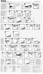
1
CELECTIC
BALLON
DURCHLAUFERHITZER
ACUMULADOR
HOT WATER CYLINDER
SERBATOIO PER ACCUMULO
BOILER
80 I
100 I
150 I
F
NOTICE D’INSTALLATION – NOTICE D’EMPLOI
D
MONTAGE –UND GEBRAUCHSANLEITUNG
SP
INSTRUCCIONES DE INSTALACION – INSTRUCCIONES DE USO
GB
INSTALLATION AND USERS INSTRUCTIONS
I
BP 64 – 78403 CHATOU CEDEX
Tél. 33 (1) 34 80 59 00 – Fax : 33 (1) 34 80 59 09
http://www.chaffoteaux-maury.com
Ref. 1005338lk
NL
ISTRUZIONI PER L’INSTALLAZIONE ISTRUZIONI PER L’USO
INSTALLATIEBOEKJE – GEBRUIKSBOEKJE
F
ENCOMBREMENT
MAßE
D
A1 POSITION AU SOL
A2 POSITION AU MUR
DIMENSIONES
SP
A1 AUF DEM BODEN
A2 AN DER WAND
A1 COLOCADO EN EL SUELO
A2 COLOCADO EN LA PARED
A1
A2
POSITION AU SOL
POSITION AU MUR
M
F
G
C
A
D
G
B
E
F
Douilles à souder Ø18/20
Schweißhülsen Ø18/20
Manguitos para soldar Ø18/20
Welded sockets Ø18/20
Manicotto a saldare Ø18/20
Lasnippels Ø18/20
H
I
D
C
L J K J L
M 3/4" G
A
B
C
D
E
F
G
H
I
J
K
L
M
Poids
À vide
Leer
gewicht
Peso
en
vacio
Weight
empty
Peso
A
vuoto
Ledig
gewicht
80 l
844
819
540
200
447
330
440
74
558
65
100
105
247
33
33
33
33
33
33
100 l
987
962
540
300
590
330
440
74
558
65
100
105
290
38
38
38
38
38
38
150 l
1270
1245
540
500
873
330
440
74
558
65
100
105
373
54
54
54
54
54
54
GB
REQUIRED SPACE
FOR INSTALLATION
A1 FREE STANDING
A2 WALL MOUNTED
I
DIMENSIONI
A1 POSIZIONE AL SUOLO
A2 POSIZIONE AL MURO
________ 2 ________
NL
AFMETINGEN
A1 STAND OP DE GROND
A2 STAND AAN DE MUUR
________ 19 ________
Hauteur manométrique en sortie de pompe CELECTIC 80 – 100 - 150
B
D1
D2
E1
E2
0,7
Pression disponible en Mb
0,6
0,5
2
3
1
9
7
8
4
0,4
6
UP 15-50 CY
0,3
UP 15-60 CY
12
5
0,2
10
0,1
0
0
100
200
300
400
500
600
700
800
900
1000
1100
1200
1300
1400
1500
1600
1700
1800
1900
2000
Débit en l/h
C
7
6
Pression disponible en mCE
6
5
5
3
2
1
4
8
4
UP 15-50 CY
3
13
UP 15-60 CY
7
2
1
0
0
100
200
300
400
500
600
700
800
900
1000
1100
1200
1300
1400
1500
1600
1700
1800
1900
2000
Débit en l/h
________ 18 ________
________ 3 ________
F
PRESENTATION
D
ALLGEMEINES
BESCHREIBUNG
SP
PRESENTACION
B
B
B
Le ballon « CELECTIC » est un système
de production d’eau chaude accumulée à
partir des chaudières mixtes Chaffoteaux
et Maury.
Der druchlauferhitzer CELECTIC bereitet
und speichert Warmwasser ab Mischkessel
Chaffoteaux et Maury.
El acumulador “CELECTIC“ es un sistema
de producción de agua caliente acumulada
acoplable a las calderas mixtas Chaffoteaux
et Maury.
Le ballon est équipé d’une pompe, d’un
boîtier électrique de raccordement, d’un
groupe de sécurité et d’un capot de
protection.
La cuve à fonds positifs est en acier
émaillé de forte épaisseur. Elle est
équipée d’une anode en magnésium
agissant comme protection électrolytique.
Le calorifugeage est assuré par une
couche de mousse polyuréthane.
Le ballon est raccordé à la partie sanitaire
chaudière par les sorties (2) et (3), à
l’installation ECS par la sortie (1) et à
l’arrivée d’eau froide par l’entrée (4).
C Principe de
fonctionnement
Der boiler ist mit einer Pumpe, einem
Anschlußschaltkasten, einer Sicherheitsvorrichtung und einer Schutzverkleidung
versehen.
Der Behälter hat einen Plusboden aus
sehr dickem emailliertem Stahl. Er besitzt
eine Anode aus Magnesium, die wie ein
elektrolytischer schutz wirkt.
Eine Schicht aus Polyurethanschaum
sorgt für die Wärmeisolierung.
Der Boiler wird an die sanitären teile des
Kessels
angeschlossen
über
die
ausflußpunkte (2) und (3), an die Warmwasserinstallation über (1) und an die
Kaltwasserzufuhr über (4).
C Shematische
Darstellung
(1) Départ ECS vers puisage
(2) Départ vers chaudière
(3) Retour ECS chaudière
(4) Arrivée eau froide
(5) Pompe
(6) Groupe de sécurité
(7) Thermostat
(8) Boîtier de raccordement électrique
(9) Capot de protection
(10) Pattes d’accrochage
(1) Abfluß Warmwasser zum Abzapfpunkt
(2) Abfluß zum kessel
(3) Warmwasser Rückflauf
(4) Kaltwasserzufuhr
(5) Pumpe
(6) Sicherheitsanlage
(7) Thermostat
(8) Anschlußschaltkasten
(9) Schutzgehaüse
(10) Halterungen
(12) Interrupteur
(13) Anode
(12) Schalter
(13) Anode
1 - Statique :
L’eau du ballon est réchauffée automatiquement par la chaudière sur ordre du
thermostat (7) qui déclenche le fonctionnement de la pompe (5).
Celle-ci a pour rôle de faire circuler l’eau
du ballon dans la chaudière et provoquer
le réchauffage de celle-ci à la température
de réglage du thermostat.
1 – Feste Teile :
Das Wasser im Boiler wird automatisch
durch den Kessel erhitzt, auf Befehl des
Thermostats (7) der die Pumpe (5)
auslöst. Die Pumpe erlaubt dem Wasser
im Boiler durch den Kessel zu fließen.
Dort wird es je nach Einstellung des
Thermostats erhitzt.
2 – Dynamique :
En puisage, l’eau froide arrivant par (4)
passe automatiquement par la chaudière,
ce qui entraîne son entrée en température
dans le ballon.
2 – Bewegliche Teile :
Bei der Warsserentnahme fließt das von
(4) kommende Kaltwasser automatisch
durch den Kessel, und löst die Erhitzung
im Kessel aus.
El acumulador viene equipado con una
bomba, una caja eléctrica de conexión, un
grupo de seguridad y una tapa de
protección.
La cuba de fondos convexos es de acero
esmaltado de gran espesor. Está
equipada por un ánodo de magnesio que
actúa como protección electrolítica.
La calorirugación queda asegurada
mediante una capa de espuma de
poliuretano.
C Esquema de principio
Principio de funcionamiento
(1) Salida ACS hacia el punto de
extaccion
(2) Salida hacia la caldera
(3) Retorno ACS de la caldera
(4) Llegada de agua fría
(5) Bomba
(6) Grupo de seguridad
(7) Termostatos
(8) Caja de conexión eléctrica
(9) Tapa protectora
(10) Patas de sujeción
(12) Interruptor
(13) Anodo
Principio de funcionamiento
El acumulador está empalmado a la parte
sanitaria de la caldera por las salidas (2) y
(3), a la instalación ACS por la solida (1) y
a la llegada de agua fría por la entrada (4).
1 – Estatica :
El agua del acumulador se recalienta
automáticamente por la caldera según la
órden del termostato (7), el cuál acciona
el funcionamento de la bomba (5).
Esta tiene como función, hacer circular el
agua del acumulador en el interior de la
caldera y provocar el recalentamiento de
ésta según la temperatura indicada en el
termostato.
2 – Dinamica :
A la extracción, el agua fría que llega por
(4) pasa automáticamente por la cladera,
con lo cual entra al acumulador una vez
calentada.
GB
Adjustments
The cylinder thermostat is set to obtain a
nominal domestic hot water temperature
of 65° C.
It is therefore important that the
temperature control for the domestic hot
water, on the boiler, is set to maximum to
ensure that the delivery of hot water
exceeds the mean temperature of the
cylinder.
Installing the cover
Once the installation has been completed
and tested, the protective cover can now
be fitted. This is done by placing it under
the bracket (or brackets in the case of the
150 ltrs) at the rear of the cylinder and
sliding it into position. Secure by
tightening the two fixing screws onto the
cylinder.
Maintenance schedule
To maintain the correct and safe operation
of the Celectic unit, it is essential that the
safety valve assembly is operated
manually at least once a month, by
depressing the lever and checking that
water discharges from the valve.
If the valve fails to discharge water, then
the Celectic unit must be turned off by
isolating both the electrical and water
supplies.
Contact your service company or agent.
Anode
It is necessary to change the anode every
two years.
To turn off the Celectic system
IMPORTANT : If the unlikely event of the
boiler failing, the Celectic should be turned
off by isolating the electrical supply via the
on/off switch.
If this is not implemented the integral
pump will continue to function and
circulate the stored water through the
secondary heat exchanger in the boiler,
thus resulting in stand-by losses.
Heating only
This can be achieved by simply setting the
summer and winter switch on the boiler to
the winter position (hot water and heating)
and the Celectic switch to the stop
position.
Heating and hot water
As heating only, except turn the Celectic
isolating switch to the on position.
NOTA : Priority will always be given to the
heating the domestic hot water cylinder.
Central heating will only operate once the
cylinder temperature has reached its set
level.
________ 4 ________
I
NL
Regulazione
Il termostato del serbatoio è regolato in
modo da ottenere dell’acqua calda
sanitaria a circa 65° C.
Cosi, conformemente all’istruzione ECS
(acqua calda sanitaria) di 60° C, portata
su alcune caldaie, é necessario regolare
la temperatura dell’acqua calda sanitaria
al massimo in tal modo che essa sia
superiore al punto di consegna del
termostato dello scaldabagno.
Regelingen
De aquastaat van de boiler is ingesteld
om sanitair warm water te bekomen van
ongeveer 65°C.
Op de wandketels, uitgerust met een
regeling van de temperatuur van het
SWW op 60°C, is het noodzakelijk om de
temperatuur van het sanitair warm water
te regelen op het maximum, zodat deze
hoger is dan het consigne-punt van de
thermostaat van de boiler.
Montaggio della cuffia di protezione
Una volta montato l’assieme, piazzare la
cuffia di protezione facendolo scivolare
sotto le due staffe dietro il serbatoio e
fissarla con le due viti sulla ghiera del
serbatoio.
Plaatsing van de beschermkap
Eens het geheel gemonteerd, de beschermkap plaatsen door deze onder de 2
haken aan de achterkant van de boiler te
schuiven en deze vast te maken door de 2
vijzen op de flens van de boiler.
Manutenzione –
utilizzazione
Cruppo di sicurezza
Al fine di assicurare il buon funzionamento
del gruppo di sicurezza è necessario farlo
funzionare almeno una volta al mese
azionando la leva e verificando che
l’acqua scorra normalmente.
Se l’acqua non scorre, è il caso di far
intervenire urgentemente uno specialista,
dopo aver spento l’apparecchio.
Anodo
E obligatorio il cambiamento di anodo tutti
i due ani.
Arresto dell’impianto
IMPORTANT : In caso di arresto della
caldaia, è necessario interrompere
l’alimentazione elettrica del serbatoio. In
caso contrario, la pompa farà inutilmente
circolare l’acqua fredda nella caldaia in
modo permanente
Riscaldamento senza acqua calda
sanitaria
Se si desidera avere il riscaldamento
dell’impiando sonza riscaldare il serbatoio,
basta accendere la caldaia lasciando
l’interruttore del serbatoio in posizione
spenta.
Riscaldamento
ed
acqua
calda
sanitaria
Al fine di ottenere l’acqua calda sanitaria,
una volta messa in funzione la caldaia,
basta ma novrare l’interrutore del
serbatoio, il che provoca il riscaldamento
dell’acqua in esso contenuta.
NOTA : Data la priorità all’impianto
sanitario della caldaia, essa non proddurà il
riscaldamento dell’impianto fino a quando
l’acqua contenuta nel serbatoio non ha
raggiunto la temperatura fissata con il
termostato. In caso di non utilizzazione
dell’impianto in periodo freddo, è
necessario svuotare il serbatoio per
prevenire il gelo. Chiudere l’arrivo d’acqua
del gruppo di sicurezza. Aprire un rubinetto
d’acqua calda. Smontare il collegamento
(Rep. B) al serbatoio. Piazzare un raccordo
del tipo tubo d’innaffiamento con un tubo di
gomma. Svuotare il serbatoio mediante
travasamento. Rimontare il collegamento.
________ 17 ________
Onderhoud – gebruik
Veiligheidsgroep
Teneinde een goede werking van de
veiligheidsgroep te verzekeren, is het
noodzakelijk om deze minimum 1 maal
per maand te spuien door de handel te
bewegen en na te kijken of het water
normaal wegloopt.
Indien het water niet afloopt, is het
noodzakelijk om dringend een vakman te
laten komen, na het toestel afgesloten te
hebben.
Anode
Het is verplicht de anode om de twee jaar
te vervangen.
Stilstand van de installatie
BELANGRIJK : in geval van stilstand van
de ketel, is het noodzakelijk op de
elektrische voeding van de boiler te
verbreken. Indien dit niet gebeurt, zal de
pomp het koud water in de boiler onnodig
doen cirkuleren.
Verwarming zonder sanitair warm
water
Indien men verwarming wenst zonder
opwarming van de boiler, volstaat het de
ketel in werking te stellen en de
schakelaar van de boiler op stand “stop”
te laten.
Verwarming met/of sanitair warm water
Teneinde sanitair warm water te
bekomen, eens de ketel in werking,
volstaat het om de schakelaar in te stellen
om de inhoud van de boiler op te warmen.
NOTA : Gezien de voorrang van het
sanitair van de ketel, zal deze de
verwarming stoppen tot het water in de
boiler opgewarmd is.
Indien de installatie niet wordt gebruikt
gedurende een gerude de winterpériode,
is het noodzakelijk de waterverwarmer te
ledigen om bevriezing te voorkomen
aankomst water aan de veiligheidsgroep
sluiten.
Een
warmwaterkraan
openen.
De
aansluiting aan de boiler demonteren (rep
B). Een annsluitstuk plaatsen van het type
sproeislang met een buis incaoutchoucc.
F
D
SP
Réglages
L’aquatast du ballon est réglé de façon à
obtenir de l’eau chaude sanitaire à 65° C
environ.
Ainsi, sur les chaudières équipées d’une
consigne ECS de 60° C, il est nécessaire
de régler la température de l’eau chaude
sanitaire au maximum, de façon à ce
qu’elle soit supérieure au point de
consigne du thermostat du ballon.
Einstellen
Der Boileraquastat ist für Warmwasser bei
65° geregelt.
So ist es bei Heizkessein mit einer
Einstelltemperatur von 60°C Warmwasser
notwendig, die Temperatur des warmen
Leitungswassers auf die maximale
Leistung einzustellen, damit sie höher als
die
Einsteltemperatur
des
Boilerthermostates ist.
Montage du capot
Une fois l’ensemble monté, placer le capot
de protection en le glissant sous les deux
pattes à l’arrière du ballon et le fixer par
les deux vis sur la virole du ballon.
Montage des Gehäuses
Nach der Gesamtmontage das Schutzgehäuse
unter
die
beiden
Hinterhalterungen schieben und mit zwei
Schrauben
auf
dem
Kesselring
festschrauben
Entretien – utilisation
Groupe de sécurité
Afin de s’assurer du bon fonctionnement
du groupe de sécurité, il est nécessaire de
faire fonctionner celui-ci au minimum une
fois par mois en actionnant le levier et en
vérifiant que l’eau s’écoule normalement.
Si l’eau ne s’écoule pas, il y a lieu de faire
venir d’urgence un professionnel, après
avoir arrêté l’appareil.
Anode
Il est obligatoire de changer l’anode tous
les deux ans.
Arrêt de l’installation
IMPORTANT : En cas d’arrêt de la
chaudière il est nécessaire de couper
l’alimentation électrique du ballon. Dans le
cas contraire, la pompe ferait inutilement
circuler de l’eau froide dans la chaudière
de façon permanente.
Chauffage sans eau chaude sanitaire
Si on désire avoir du chauffage sans
provoquer le réchauffage du ballon, il suffit
de mettre en route la chaudière en
laissant l’interrupteur du ballon en position
arrêt.
Chauffage et/ou eau chaude sanitaire
Afin d’obtenir de l’eau chaude sanitaitre,
une fois la chaudière en fonctionnement, il
suffit de manœuvrer l’interrupteur du
ballon ce qui provoque le réchauffement
de l’eau contenue dans celui-ci.
NOTA : Etant donné la priorité au
sanitaire de la chaudière celle-ci ne
produira du chauffage que lorsque le
ballon aura été réchauffé.
En cas de non utilisation de l’installation
en période froide, il est nécessaire de
vidanger le ballon pour prévenir le gel.
Fermer l’arrivée d’eau du groupe de
sécurité.
Ouvrir le robinet d’eau chaude.
Démonter le raccordement (rep. B) au
ballon.
Placer un raccord type raccord de tuyau
d’arrosage avec un tube caoutchouc.
Vidanger le ballon par siphonnage.
Remonter le raccordement (Rep. B).
Wartung – Benutzung
Anode
Zweite
Jahr
Heizen ohne warmwasserproduktion
wames leitungswasser.
Will man die Heizung anstellen ohne den
Boiler aufzuheizen, genügt es den Kessel
einzustellen indem der boilerschalter auf
“Stop“ steht.
Heizung und/oder wames leitungswasser
Will man warmes Wasser haben während
der Kessel funktioniert, genügt es den
Boilerschalter einzustellen.
Bemerkung : Da die Priorität beim
Sanitärwert des Kessels liegt, wird dieser
erst heizen, wenn das Wasser im Boiler
warm ist.
Wird die Anlage bei kalter Temperatur
nicht gebraucht, muß der Boiler geleert
werden, um ein einfrieren zu verhindern.
Die Wasserhahn aufdrehen.
Den fitting (Resp. B) zum boiler
abmontieren.
Ein
Verbindungsstück
(z.
B.
gartenanschluß) mit Schlauch anbringen
und den boiler damit leeren.
Den fitting (Resp. B) wieder aufmontieren.
________ 16 ________
Montaje de la tapa
Una vez montado el conjunto, colocar la
tapa de proteccián deslizándola dende las
dos patas situadas detrás del acumulador
y fijarlo mediante los dos tornillos sobre la
carcasa del acumulador.
Mantenimiento – uso
Sicherheitsanlage
Um das perfekte Funktionieren der
Sicherheitsanlage zu prüfen, diese mindestens ein mal im Monat kontrollieren ;
den Hebel in Gang setzen und prüfen daß
das Wasser normal abläuft.
Wenn das Wasser nicht ausfließt, den
Apparat abstellen und sofort den
Wartungsdienst rufen.
Die anode muß jedes
geweehselt werden.
Reglajes
El acuastato del acumulador esta
regulado de forma qua se pueda obtener
agua caliente sanitaria a 65° C
aproximadamente.
En las calderas equipadas con una
temperatura del agua caliente sanitaria a
60°C, es necesario ajustar la temperatura
del agua caliente sanitaria al máximo,
para que sea superior al punto de
consigna del termostato del acumulador.
Grupo de seguridad
Con el fin de asegurar un buen
funcionamiento del grupo de seguridad,
es necesario hacerlo funcionar como
mínimo una vez al mes, accionando la
palanca y verificando que el agua corre
normalmente. Si el agua no circula, avisar
urgentemente al S.A.T., una vez parado el
aparato.
Anodo
Es obligatorio cambiar el ánodo cada dos
años.
Paro de la instalación
IMPORTANTE : En caso de paro de la
caldera,
es
necesario
cortar
la
alimentación electrica del acumulador. En
caso contrario, la bomba haría circular
inutilmente el agua fría por la caldera
permanentemente.
Calefacción sin agua caliente sanitaria.
Si deseamos tener calefacción sin
provocar
el
recalentamiento
del
acumulador, basta con poner en marcha
la caldera dejando el interruptor del
accumulador en posición paro.
Calefacción Y/O agua caliente sanitaria
Con el fin de obtener agua caliente
sanitaria, con la caldera funcionando en
calefacción, basta con maniobar el
interruptor del acumulador, lo cual
provoca el recalenta-miento del agua que
éste contiene.
NOTA : Dada la proridad del agua
caliente sanitaria de la caldera, ésta no
proporcionará calefaccion hasta que el
acumulador no esté recalentado.
En caso de no utilizar la instalación en
temporada de frío, es necesario vaciar el
acumulador para prevenir las heladas.
Cerrar la llegada de agua del grupo de
seguridad.
Abrir un grifo de agua caliente
Desmontar el empalme (loc. B) del acumulador.
Colocar un racor tipo racor de tubo de
grifo de riego con un tubo de cauchouc.
GB
DESCRIPTION
B
The CELECTIC is a hot water system for
use in conjunction with Chaffoteaux et
Maury combination boilers.
The Celectic comes complete with a pump,
and electrical connection box, a safety
valve assembly and protective cover.
The efficient design of the Celectic is
further
enhanced
by
its
robust
construction of enamelled steel together
with its polyurethane foam insulation
which ensures minimal heat losses.
A sacrificial magnesium anode is fitted to
the cylinder to give added protection
against any electrolytic action that may
occur.
C Schematic diagram
I
DESCRIZIONE
B
II serbatoio « CELECTIC » è un sistema
di produzione di un accumulo di acqua
calda da abbinare dalle caldaie miste
Chaffoteaux et Maury.
Lo scaldabagno é munito di una pompa, di
una scatola elettrica di collegamento, di
un gruppo di sicurezza e di un coperchio
di protezione.
II contenitore a fondi positivi è in acciaio
smaltato di grande spessore. Esso è
dotato di un anodo in magnesio operante
come protezione elettrolitica.
L’isolamento termico è assicurato da uno
strato di schiuma poliuretana.
C Schema di principio
(1) Mandata ACS verso prelievo
(2) Mandata verso caldaia
(3) Ritorno ACS caldaia
(4) Ingresso acqua fredda
(5) Pompa
(6) Valvola
(7) Termostato
(8) Scatola di collegamento elettrico
(9) Cuffia di protezione
(10) Staffe d’aggancio
(12) On/off switch
(13) Anode
(12) Interruttore
(13) Anodo
1 – Heating of the stored water :
The stored is automatically heated by the
combination boiler and is controlled by a
thermostat fitted to the Celectic cylinder.
On demand this thermostat energises the
pump which then circulates the stored
through the secondary heat exchanger of
the combination boiler until the desired
temperature is obtained.
2 – Using the stored hot water :
When a hot outlet is opened, cold water
from the mains supply enters the Celectic
system via the secondary heat exchanger
in the combination boiler, thus being preheated before it is allowed to mix with the
stored hot water.
VOORSTELLING
B
De waterverwarmer « CELECTIC » is een
systeem van geaccumuleerde warmwaterproduktie, werkend op een mixte
wandketel Chaffoteaux et Maury.
De boiler is uitgerust met een pomp, met
een
elektrische
doos,
een
veiligheidsgroep en een beschermkap.
De kuip met “positieve bodem” is in
geëmailleerd staal van een grote dikte. Zij
is uitgerust met een magnesiumanode
werkend als elektrolyse bescherming.
De warmte wordt behouden door een
polyurethaanmousselaag.
C Werkingsschema
(1) Hot water outlet
(2) Outlet to boiler
(3) Hot water inlet
(4) Cold water inlet
(5) Pump
(6) Safety valve assembly
(7) Thermostat pocket
(8) Electrical connection box
(9) Cover
(10) Fixing brackets
Operating principles
The cylinder is connected to the
combination boiler in the following manner :
(1) Is connected to the hot water outlets to
be served. (2) Is connected to the cold
water inlet on the boiler. (3) Is connected to
the domestic hot water outlet on the boiler.
(4) Is connected to the incoming cold water
mains supply.
NL
Principio di funzionamento
II serbatoio è collegato al circuito sanitaria
caldaia tramite le uscite (2) e (3),
all’impianto ACS tramite l’uscita (1) e
all’arrivo d’acqua fredda tramite l’entrata
(4).
1 – Statica :
L’acqua del serbatoio viene riscaldata
automaticamente
dalla
caldaia
su
commando del termostato (7) che inserisce
la pompa (5).
Questa ha il compito di far circolare
l’acqua del serbatoio nella caldaia e
provocare il riscaldemento di quest’ultima
alla temperature di regolazione del
termostato.
2 – Dinamica :
In fase de pralievo, l’acqua fredda che
arriva da (4), passa attraverso lo
scambiatore della calddia, viene in questo
modo riscaldota, prima di entrare nel
serbatoio.
________ 5 ________
(1) Aankomst sanitair koud water
(2) Vertrek naar de wandketel
(3) Retour sanitair warm water ketel
(4) Vertrek sanitair warm water naar
aftappunt
(5) Pomp
(6) Veiligheidsgroep
(7) Thermostaat
(8) Elektrische aansluitdoos
(9) Beschermkap
(10) Beugels
(12) Schakelaar
(13) Anode
Werkingsprincipe
De boiler wordt aangesloten op het
sanitaire gedeelte van de ketel door de
uitgangen (2) en (3), aan de installatie
SWW door de uitgang (1) en aan de
aankomst van het koud water door de
ingang (4).
1 – Statisch :
Het water van de boiler wordt automatisch
opgewarmd door de ketel op bevel van de
thermostaat (7), welke de werking van de
pomp (5) op gang brengt.
Deze heeft de taak om het water van de
boiler te doen circuleren in de ketel en
veroorzaakt zo de opwarming van deze tot
de ingestelde temperatuur van de
thermostaat.
2 – Dynamisch :
Bij aftapping komt het aankomende koud
water door (4) automatisch door de ketel,
welke op temperatuur gebracht wordt in
de boiler.
F
PERFORMANCES
Le CELECTIC fonctionne
chaudières suivantes :
CELTIC 2.30 Rsc b
CELTIC 2.20 Rsc b
CELTIC 2.23 HPS
CELTIC 2.20 FF Rsc b
CELTIC 2.23 FF HPS
CELTIC 2.20 Turbo HPS
CELTIC 2.24 Rsc b
SIAM CF
SIAM FF
GM 2.20 Rsc b
NECTRA
avec
les
D
LEISTUNGEN
Der CELECTIC Boiler funktionniert mit
folgenden Kesseln :
NEWTECH 2.20 FF
NEWTECH 2.20
NEWTECH 2.24
NEWTECH 2.20 HPS
SIAM CF
SIAM FF
GM 13.20 Rsc b
SP
PRESTACIONES
El CELECTIC funciona con las siguientes
calderas :
CELTIC 18.23 RSc E
CELTIC 2.20 RSc E
CELTIC 2.20 FF RSc E
CELTIC 2.30 RSc E
CELTIC 2.23 HPS
CELTIC 2.23 FF HPS
SIAM CF
SIAM FF
Tableau donné pour une chaudière de 23 kW*
Diese tabelle betrifft einen 23 kW Heizkessel*
Cuadro indicativo para una caldera di 23 kW*
80 l
100 l
150 l
Durée de chauffe 15 à 60° C (min)
Aufheizdauer 15 bis 60° C (min)
Duración de calentamiento 15 a 60° C (min)
25
30
40
Débit spécifique l/min
Spezifische Durehflußmenge l/min
Caudal específico l/min
17
GB
COMMISIONING
20,9
Consommation d’entretien KWh/24 h
Normalverbrauch KWh/24 h
Consumo de mantenimiento KWh/24 h
1,58
1,63
1,94
Constante de refroidissement
Erkältungskonstante
Constante de enfriamiento
0,493
0,408
0,323
Classe de protection électrique
Elektrischer Schutzwert
Clase de protección eléctrica
IPX4
IPX4
MESSA IN
FUNZIONE
NL
1 – Turn the summer and winter switch to
the midway off position on the boiler, to
ensure that the appliance does not come
into operation during the filling period.
1 – Posizionare l’interruttore della caldaia
in posizione “arresto” al fine di evitare
l’avviamento in fase di riempimento e di
spurgo.
2 – To fill the system, open the cold water
inlet valve on the boiler. Open one of the
hot water outlets on the installation
preferably the furthest from the cylinder.
Check for any leaks and re-make and
tighten connections as necessary.
2 – Riempire lo scaldabagno.
Aprire il rubinetto dell’acqua fredda della
caldaia.
Aprire un rubinetto d’acqua calda
dell’impianto per spurgare l’aria e mettere
il gruppo in posizione.
« Alimentazione » .
Per accelerare il riempimento é possibile
aprire il by-pass (fig. B, rif. 11) a mezzo
del bottone fresato (Per l’apertura svitare.
Per la chiusara : avvitare).
3 – It is essential that the cylinder and
pipework are flushed to ensure safe and
correct operation. Open the remaining hot
water outlets and allow the water to flow
for approximately two minutes. This will
ensure that all the air is purged from the
circuits and any remaining debris is
removed.
4 – Purge the pump.
17,6
I
An isolating switch is incorporated within
the electrical control box to allow the
Celectic to be turned off whilst leaving the
boiler fully operational.
3 – Sciacquare il serbatoio
Questa operazione permette di assicurare
la pulizia dell’apparecchio. Per fare ció,
lasciar
scorrere
l’acqua,
dopo
il
riempimento, per qualche minuto. Ció ha il
vantaggio di spurgare il circuito.
INDIENSTSTELLING
1 – De schakelaar van de ketel op stand
“Stop” zetten teneinde deze te beletten te
starten tijdens de vulling en ontluchting.
2 – De boiler vullen
Open de koudwaterkraan
wandketel.
3 – De boiler spoelen
Dit laat toe het toestel te reinigen. Het
water laten weglopen gedurende enkele
minuten na de vulling. Dit heeft het
voordeel het circuit te ontluchten.
4 – De pomp ontluchten door de stop van
de pompstarter los te vijzen.
4 – Spurgare la pompa allentando il tappo
del propulsore di quest’ultima.
Electrical connections
Collegamento elettrico
Elektrische aansluitingen
The Celectic requires a 240 volt 50 Hz
single phase supply and must be
connected as shown in the diagram on
page 10 (flexible cable not supplied).
Both the Celectic and the combination
boiler must be earthed.
An isolating switch is incorporated within
the electrical control box to allow the
Celectic to be turned off whilst leaving the
boiler fully operational.
Il collegamento elettrico del serbatoio si
effectua tramite un cavo a 3 conduttori
(fase, neutro e terra) non fornito.
Questo deve essere collegato sulla
morsettiere come indicato in figura.
L’interruttore dello scaldabagno serve
solamente a togliere la funzione acqua
calda sanitaria ma non arresta la funzione
acqua calda sanitaria ma non arresta la
funzione riscaldamento.
NOTA : There are no electrical connections
between the boiler and the cylinder.
NOTA : Non c’è nessun collegamento
elettrico tra la caldaia e il serbatoio.
De elektrische aansluiting van de boiler
uitvoeren door middel van een kabel met 3
geleiders (F, N aarding) niet meegeleverd.
Deze wordt aangesloten op de aansluitklemmen volgens schema.
De schakelaar van de boiler dient alleen
om de produktie van sanitair warm water
te stoppen zonder de verwarmingsfunktie
te stoppen.
NOTA : Er is geen enkele elektrische
aansluiting tussen de ketel en de boiler.
* Les valeurs du tableau sont établies pour un ballon raccordé par le haut et placé sous la chaudière.
* Diese angaben wurden für einen unter dem Kessel stehenden Boiler mit Obenanschluß aufgestellt.
* Los valores del cuadro han sido establecidos para un acumulador empalmado por arriba.
Wir raten den Durchlauferhitzer so nah
wie
möglich
neben
dem
Kessel
anzubringen, um zu verhindern, daß die
Leistungen des Systems durch last-und
Wärmeverluste
in
den
Leitungen
herabgesetzt werden.
Cependant une longueur équivalente à 20
m de tuyauterie 16 x 18 est possible (ce
qui correspond à 10 m aller/retour) sans
tenir compte des accidents de parcours
qui sont à déduire de cette longueur
maximum.
Es ist jedoch möglich ein 20 m langes
Rohr (16 x 18) zu benützen, das heißt 10
m hin und zurück, ohne Berücksichtigung
verschiedener Hindernisse, die von der
maximalen Gesamtlänge abzuziehen sind.
No obstante puede cololarse una tubería
16x18, de una longitud equivalente a 20
m, lo que corresponde a 10 m ida y
vuelta, sin tener en cuenta los accesorios
del circuito que deben dedurcirse de esta
longitud máxima.
Darüber hinaus ist es notwending, die
Anschlußrohre zu isolieren.
Es necesario calorifugar las tuberfas de
empalme.
Der boiler kann an jedem beliebigen Ort
aufgestellt werden (schrank, küche, keller
usw...) unter Berücksichtigung der hier
angegebenen Montageanweisungen.
El acumulador puede estar colocado en
cualquier sitio (armario, cocina, sótano,…)
siempre y cuando se respeten las
instrucciones de montaje.
Il est nécessaire de calorifuger les tuyaux
de raccordement.
Le ballon peut être placé n’importe où
(placard, cuisine, cave…) sous réserve
que les instructions de montage soient
respectées.
________ 6 ________
Se recomienda colocar el acumulador lo
más cerca posible de la caldera, con el fín
de no disminuir las prestaciones de este
sistema, debido a las pérdidas de carga y
a las pérdidas térmicas en las tuberías.
de
Open een warmwaterkraan van de
installatie om te ontluchten en plaats de
groep op de stand “voeding”. Teneinde de
vulling te versnellen, kunt U de by pass
openen (fig. B rep 11), met behulp van
een gekartelde knop (opening door los te
vijzen, sluiting door vast te vijzen).
IPX4
Il est recommandé de placer le ballon
aussi près que possible de la chaudière
afin de ne pas faire chuter les
performances du système du fait des
pertes de charge et des pertes thermiques
dans les tuyauteries.
van
Thermostat
Termostato
Thermostaat
Terminal
Morsettiera
Aansluitklem
Earth
Terra
Aarding
N
Neutral
Nautro
Neutraal
P
220V mono ~ 50Hz
Live
Fase
Fase
Switch with indicator light
Interruttore con spia
Schakelaar met lampje
Fuse
Fusibile
Zekering
________ 15 ________
F
MISE EN SERVICE
D
INBETRIEBNAHME
SP
PUESTA EN
MARCHA
1 – Placer l’interrupteur de la chaudière en
position
« arrêt »
afin
d’éviter
le
démarrage de celle-ci en phase de
remplissage et de purge.
1 – Den kesselschalter auf « stop » stellen
um ein Funktionieren des Kessels
während der Füllphase oder des
Ablassens zu verhindern.
1 – Colocar el interruptor de la caldera en
posición “paro“, a fin de evitar que la
misma se ponga en marcha cuando esté
en fase de llenado o de purga.
2 – Remplir le ballon
Ouvrir le robinet eau
chaudière.
2 – Boiler füllen
Kaltwasserhahn des Heizkessels öffnen.
2 – Llenar el acumulador.
Abrir la llave de entrada del agua fría a la
caldera.
froide
de
la
Ouvrir un robinet d’eau chaude de
l’installation pour purger l’air et placer le
groupe dans la position « Alimentation ».
Afin d’accélérer le remplissage, vous
pouvez ouvrir le by-pass (fig. B, rep. 11), à
l’aide du bouton moleté (ouverture en
dévissant, fermeture en vissant).
Vérifier que la bride et tous les joints des
canalisations sont bien étanches.
3 – Rincer le ballon
Cette opération permet d’assurer le
nettoyage de l’appareil. Pour ce faire,
laisser s’écouler l’eau, après remplissage,
pendant quelques minutes. Ceci a
l’avantage de purger le circuit.
4 – Purger la pompe en desserrant le
bouchon du lanceur de celle-ci.
Einen Warmwasserhahn der Anlage zur
Entlüftung öffnen und den Satz auf
“Alimentation“ (Einlauf) stellen. Um das
Füllen zu beschleunigen, kann der Bypass
(Abb. B, Ref. 11) anhand des Rändelknopfes
geöffnet werden (beim Öffnen auf-, beim
Schliessen zuschrauben).
Darauf achten, daß der Flansch und alle
Leitungsdichtungen wasserdicht sind.
3 – Den Boiler spülen.
Den Apparat wie folgt reinigen : das
Wasser einige minuten nach dem Füllen
überlaufen lassen. So werden zugleich die
Leitungen gereinigt.
4 – Zum Entlüften der Pumpe den Deckel
der Ansaugvorrichtung lösen.
GB
PERFORMANCE
The CELECTIC may be used
conjunction with the following boilers :
CELTIC FF
STERLING FF
STERLING OF
CELTIC +
I
in
Abrir un grifo de agua caliente de la
instalación para purgar el aire y colocar el
grupo en posición « Alimentación ».
Con el fin de acelerar el llenado, se puede
abrir el by-pass (figura B – indicación 11),
con el botón moleteado (destornillar para
abrir, atornillar para cerrar).
Sacar la cubierta protectora y verficar la
estanqueidad de la brida y de lodas las
juntas de las conducciones.
3 – Limpiar el acumulador.
Esta operación permite asegurar la
limpieza del aparato. Para efectuarlo,
dejar vaciar el agua y después rellenarlo,
durante algunos minulos. Esto tiene como
ventaja el purgar el circuito.
4 – Aflojar el tapón de arranque de la
bomba para purgala.
Raccordement électrique
Elektrischer Anschluß
Conexión eléctrica
Le raccordement électrique du ballon
s’effectue par l’intermédiaire d’un câble 3
conducteurs (phase, neutre et terre) non
fourni.
Celui-ci est raccordé sur le bornier selon
figure.
L’interrupteur du ballon sert uniquement à
supprimer la fonction eau chaude sanitaire
sans arrêter la fonction chauffage.
Der Schalter des Boilers dient lediglich
zum Abschalten der Funktion warmes
Leitungswasser ; die Heizung wird nicht
ausgeschaltet.
El interruptor del acumulador sólo sirve
para suprimir la función agua caliente
sanitaria
sin
detener
la
función
calefacción.
NOTA : No hay ninguna conexión
eléctrica entre la caldera y el acumulador.
NOTA : Il n’y a aucun raccordement
électrique entre la chaudière et le ballon.
PRESTAZIONI
II CELECTIC funziona con le seguenti
caldaie
MULTI VENTI TOP
MULTI VENTI 4 TOP
CERAR VENTI TOP
CERAR VENTI 4 TOP
MULTI VENTI FF TOP FF
CERAR VENTI FF TOP FF
SIAM CF
MC 13.20
CELTIC 2.26 Rsc b
SIAM FF
MC 13.20 FF
NL
PRESTATIES
De CELECTIC werkt met de volgende
wandketels :
NEWTECH 2.20 FF
NEWTECH 2.20
NEWTECH 2.24
NEWTECH 2.20 HPS
SIAM CF
SIAM FF
GM 13.20 Rsc b
NEWTECH 2.20 FFHPS
Data given for a 23 kW boiler output*
Tabella data per una caldaia di 23 kW*
Gegeventabel voor een wandketel van 23 kW*
80 l
100 l
150 l
Heat recovery time at 15 to 60° C (min)
Durata di riscaldamento da 15 a 60° C (min)
Opwarmingstijd 15 tot 60° C (min)
25
30
40
Flow rate ltrs/min
Portata specifica l/min
Specifiek debiet l/min
17
17,6
20,9
Stand-by consumption kWh/24 hrs
Consumo di mantenimento kWh/24 h
Onderhoudsverbruik kWu/24 u
1,58
1,63
1,94
Stand-by coefficient watts/sq.mtr/° C
Constante di raffreddamento
Afkoelingsconstante
0,493
0,408
0,323
Type of electrical protection
Classe di protezione elettrica
Elektrische beschermingsgraad
IPX4
IPX4
IPX4
* the figures quoted in the above table refer to a top outlet cylinder connected directly beneath the combination boiler.
* I valori della tabella sono stabiliti per un sebatoio collegato dall’alto e piazzato sulla caldaia.
* De waarden van deze tabel zijn opgemaakt voor een watervermarmer boven aangesloten en geïnstalleerd onder de wandketel.
Thermostat
Thermostat
Termostato
Bornier
Anschlußklemme
Borne
Terre
Erde
Tierra
N
Neutre
Neutral
Neutro
P
220V mono ~ 50Hz
Phase
Phase
Fase
Interrupteur avec voyant
Schalter mit signallampe
Interruptor con indicator
Fusible
Sicherung
Fusible
________ 14 ________
To maximise system performance and
minimise both pressure and thermal
losses due to extented pipe runs, it is
recommended that the cylinder is installed
as close to the boiler as possible.
Si raccomanda di sistemare il serbatoio il
più vicino possibile alla caldaia al fine di
non far diminuire le prestazioni del
sistema per le perdite di carica e per le
perdite termiche nelle tubature.
Het is aanbevolen om de boiler zo dicht
mogelijk bij de ketel te plaaten, teneinde
de prestaties niet te doen dalen, door
drukverliesen en thermische verliezen in
de leidingen.
However, the Celectic can be installed up
to a maximum of 10 mtrs away from the
boiler provided that frictional losses are
kept to a minimum, through the use of
machined bends rather than elbows and
that all pipework is insulated to reduce
thermal losses.
Comunque una lunghezza equivalente a
20 m di tuberia 16x28 è possibile (il che
corrisponde a 10 m andata e ritorno)
senza tener conto degli inconvenienti di
percorso che sono da dedure a questa
massima lunghezza.
Niettemin is een equivalente lengte van 20
m buisleiding 16x28 mogelijk (welke
overeenkomt met 10 m vertrek en retour)
zonder rekening te houden met de
verschillende obstakels op het circuit,
welke moeten afgetrokken worden van
deze maximum lengte.
This flexibility allows the Celectic to be
installed in cupboards, kitchens, cellars,
etc. remote from the boiler, provided that
the installation instructions are adhered to.
E necessario isolare termicamente i tubi di
collegamento.
II serbatoio puo essere collocato ovunque
(stipo, cucina, cantina purché siano
rispettate le istruzioni di montaggio).
________ 7 ________
Het is eveneens noodzakelijk om de
aansluitleidingen thermisch te isoleren.
De boiler mag gelijk waar geplaastst worden
(muurkast, keuken, kelder,…) onder
voorbehoud dat de montageinstrukties
gerespekteerd worden.
F
EXEMPLES DE
MONTAGE
D
MONTAGEBEISPIELE
SP
EJEMPLOS DE
MONTAJE
D1 Ballon au sol
D2 Ballon au mur
D1 Boiler auf Boden
D2 Boiler an der Wand
D1 Acumulador colocado en el suelo
D2 Acumulador colocado en la pared
Ce ballon est livré pour être monté
verticalement, raccordements vers le haut.
Dieser Boiler ist für eine vertikale Montage
vorgesehen, wobei die Anschlüsse oben
angebracht sind.
Este acumulador se instala verticalmente,
conexiones hacia arriba. Sin embargo,
puede
instalarse
verticalmente,
conexiones hacia abajo, modificando la
configuración de éstas (ver esquema
página 12).
Il est cependant possible de le monter
verticalement, raccordements vers le bas,
ce qui nécessite une adaptation (voir
schéma p.12).
Type de raccordements (page 3)
Es ist jedoch möglich, ihn vertikal mit nach
unten
gerichteten
Anschlüssen
zu
montieren (Adaptation seihe Zeichnung
Seite 12).
Hydraulische Anschlüsse
E1
Ce montage de base permet le soutirage
d’ECS uniquement à travers le ballon.
En conséquence, après l’arrêt de
l’installation, il faut attendre le réchauffage
du ballon pour pouvoir disposer d’eau
chaude sanitaire.
E2
En réalisant un deuxième piquage d’ECS
à la sortie de la chaudière, cela permet
d’obtenir sur une partie choisie de
l’installation, de l’eau chaude ne passant
pas par le ballon. En conséquence, il est à
tout moment possible de disposer de l’eau
chaude à ces postes de puisage.
Il est nécessaire de rajouter à l’installation
un clapet anti-retour entre le piquage et le
ballon. Ce clapet doit être monté passant
dans le sens chaudière vers ballon.
E1
Es handelt sich um die Grundmontage,
die
die
Entnahme
von
warmem
leitungswasser nur ürber den Boiler
ermöglicht.
Daher muß nach Ausschalten der Anlage
bis zum vollständigen Erwärmen des
Boilers gewartet werden, um wieder über
warmes Leitungswasser zu verfügen.
E2
Durch eine zusätzliche Warmwasseranzweigung am Heizungsauslauf ist es
möglich, in einem bestimmten Bereich der
Anlage Warmwasser zu erhalten, das
nicht durch den Boiler läuft. An diesen
Zapfstellen kann also jederzeit über
Warmwasser verfügt werden.
Hierzu wird zusätzlich ein Rücklaufventil
zwischen Anzweigstelle und Boiler
installiert. Dieses Ventil muß in Richtung
Heizkessel. Boiler montiert werden.
________ 8 ________
Tipos de empalmes hidraulicos
E1
Esta instalación básica permite sacar
agua caliente sanitaria únicamente por el
acumulador.
Por consiguiente, una vez desconectado
el aparato, es necesario esperar el
recalentamiento del agua de la cuba para
obtener agua caliente sanitaria.
E2
Al añadir una segunda toma de agua
caliente sanitaria a la salida de la caldera,
es posible obtener, en una parte
específica de la installación, agua caliente
sanitaria sin que pase por la cuba. Por co
siguiente, eso permite obtener agua
caliente en estos puntos de extracción a
cada momento.
Es necesario instalar una válvula antiretorno entre la toma directa y la cuba.
Esta válvula debe estar instalada en
dirección hacia la cuba (circulación del
agua desde la caldera hacia la cuba).
GB
Installing the Celectic with
bottom connections
lnstalling the Celectic with
Whilst the Celectic is designed for vertical
bottom
fixing only,connections
it is quite straightforward to
convert from top outlet connections,
supplied as standard, to bottom outlet
Whilst the Celectic is designed for
connections by carrying out the following
vertical
fixing
only, it is quite
modifications.
straightforward to convert from top outlet
connections,
as Xstandard,
to
1 – Completelysupplied
dismantle the
pipe.
bottom outlet connections by carrying
out
the
following
modifications.
2 –
Loosen
the nuts
on connections (1)
and (4) on the jig plate (do not disconnect
1 - Completely
remove
completely).
Disconnect
thetube
hotX water
outlet
regulator
connection
(A)
the
2 - Completely unscrew the and
brass
tube (B) from the cylinder.
nuts A and B (do not unscrew the
plastic
coupling,
is flexible
fixed with
3 – Turn
the inlet
elbow, it
the
tube,
paste).
and theseal
hot water
outlet regulator, through
180° to face away from the cylinder.
3-
Turn over the pump-tube-plate
unit.
4 – Turn
the entire assembly through 180°
and
the inlet
elbow between
4 - connect
Refit tube
Y (supplied
as an (1
and A). The flexible tube between (3 and
accessory)
in
place
of
tube X.
B) and the hot water outlet regulator
between
(4 and
C).ATighten
connections
5 - Screw
nuts
and B back
on.
(1 and 4) on the jig plate.
6-
I
NL
Caso di un montaggio con
raccordi verso il basso
Caso di un montaggio con
1 – Smontare completamente il tubo X
raccordi verso il basso
Opstelling aansluitingen
naar beneden
Opstelling aansluitingen
1 – De X buis in z’n geheel demonteren.
naar beneden
2 – Allentare i dadi 1 e 4 senza smontarli ;
e svitare i dadi A e B
2 – Los de moeren 1 en 4 zonder deze te
demonteren, en los de moeren A en B
1-
1-
Smontare totalmente il tubo X.
3 – Girare il complesso pompa – tubo –
piastrina.
2 - Svitare completamente i dati
ottone A e B (non svitare i
De buis X volledig demonteren .
3 – Draai het geheel pomp – buis –
2platine.
- De moeren A en B van messing
volledig losdraaien (de plastic
4 – Montare
di nuovo
il complesso
manicotti
di plastica,
sono sullo
scaldabagno
; stringere
i dadi
e 4.
montati
con pasta
di 1tenuta).
4 – Hermonteer
hetlosdraaien,
geheel op de boiler.
bussen niet
De moeren
1 en 4 deze
vastvijzen.
aangezien
met afdichtkit
53 -– Rimontare
il tubo
Y (fornito
Capovolgere
I'insieme
pompa in
accessorio)
posto del tubo X.
tubo al
piastra.
5 – De buis Y weer monteren op de plaats
(als hulpstukpomp
leveren).
3van
- buis
HetX samenstel
buis plaat
64 –
che
tutti iYgiunti
siano
- Assicurarsi
Rimontare
il tubo
(fornito
in a
posto. accessorio) al posto del tubo X.
6 – Zich ervan verzekeren dat de
wel degelijk
afsluiten.
4dichtingen
- De buis
Y (als accessoire
5-
Ristringere i dadi A e B.
6-
Accertarsi Che tutti i giunti siano
ben sistemati.
Check that all the seals are
5 – Putproperly
back theinYplace.
pipe (provided as an
accessory) in place of the X pipe.
NB
thatallall
washers
are
in
NB: :Ensure
Ensure that
washers
are in
place
place
correctly
and
that
correctly
and that all
joints
are all
tight.joints
Check
fortight.
leaks. Check for leaks.
are
13 ________
________ 13
zijn aangebracht).
omdraaien
geleverd) in de plaats van buis X
monteren.
5-
De moeren A en B weer
aandraaien.
6-
De goede plaatsing van alle
pakkingen controleren.
F
D
Cas de montage
raccordement vers le bas
Cas de montage
1 – Démonter complètement le tube X.
raccordement vers le bas
2 – Dévisser complètement
plastique A et l’écrou laiton B.
l’écrou
1 - Démonter complètement le tube X.
3 – Démonter le manchon plastique
C. complètement les écrous
2 isolant
- Dévisser
laiton A et B (ne pas dévisser les
4 manchons
– Remonter
le manchon
plastique,
ils sontplastique
montés
isolant C sur D (couple de serrage entre
avec de la pâte d'étanchéité).
15 et 20 Nm)
3 - Retourner l'ensemble pompe – tube
5 platine.
– Retourner l’ensemble pompe – tube
SP
Montage mit anschluss
nach unten
Caso de instalación con
conexiones hacia abajo
Montage mit anschluss
1 – Den Rohr X ganz demontieren.
nach unten
Caso de instalacion con
1 – Desmontar completamente el tubo X.
conexiones hacia abajo
2 – Muttern 1 und 4 lösen ohne
abzuschrauben, Muttern A und B
1 -abschrauben.
Das Rohr X vollständig ausbauen.
2 – Aflojar las tuercas 1 y 4 sin
desmontarlas y destornillar las tuercas A y
1 -B.Desmontar totalmente el tubo X.
– Den
Satz Pumpe A
– und
RohrB– Platte
2 -3 Die
Messingmuttern
umdrehen.
vollkommen aufschrauben (die
Kunststoffhülsen nicht aufschrauben,
4 sie
– Diesen
wieder
an den Boiler
sind mitSatz
einer
Dichtungsmasse
montieren. Muttern 1 und 4 wieder
montiert).
festschrauben.
– Dar la vuelta
al conjunto bomba
2 -3Destornillar
completamente
las – tubo
–tuercas
plantilla.de latón A y B (no
destornillar los manguitos de plástico
4 – Montar de nuevo el conjunto en la
pues están montados con masa de
cuba. Apretar las tuercas 1 y 4.
estanqueidad).
platine.
3 - Umdrehen der Einheit Pumpe Rohr
5 – Den Rohr Y wieder montieren am
Platte.
– Montar
tubo
Y (proporcionado
como
3 -5Dar
vueltael al
conjunto
bomba, tubo,
accesorio) en lugar del tubo X.
platina.
accessoire) à la place du tube X.
4 - Einbau des Rohres Y (wird als
6 Zubehör
– Sichgeliefert)
vergewissern,
an Stelledaß
des alle
Dichtungen festsitzen.
Rohres X.
– Asegurarse
deelque
todas
las juntas
4 -6Volver
a montar
tubo
Y (incluido
estén
colocadas.
comobien
accesorio)
en el lugar del tubo
X.
5 - Festziehen der Muttern A und B.
5 - Apretar las tuercas A y B.
6 - Überprüfen, o balle Dichtungen
einwandfrei eingebaut sind.
6 - Asegurarse de que todas las juntas
estén en su sitio.
4 - Remonter le tube Y (fourni en
6 accessoire)
– Remonterà la
le place
tube du
Y tube
(fourni
X. en
5 - Resserrer les écrous A et B.
7 – S’assurer que tous les joints sont bien
6 en
- S'assurer
que tous les joints sont bien
place.
en place.
Platz X (als Zubehör liefern).
GB
INSTALLATION
EXAMPLES
ESEMPI
DI MONTAGGIO
NL
VOORBEELDEN
VAN AANSLUITING
D1 Free standing cylinder
D2 Wall mounted cylinder
D1 Serbatoio al suolo
D2 Serbatoio al muro
D1 Boiler stand op de grond
D2 Boiler hangend aan de muur
These models are all designed for vertical
mounting with top outlet connections.
II presente scaldabagno é consegnato per
essere montato verticalmente, collegamenti
verso l’alto.
Deze boiler wordt geleverd om vertikaal
gemonteerd te worden, aansluitingen naar
boven.
E tuttavia possibile montarlo verticalmente,
collegamenti verso il basso ; ciò necessita
un adattamento (vedi schema pag. 12).
Het is evenwel mogelijk om hem vertikaal
aan te sluiten, aansluitingen naar
onderen, dit vraagt wel een aanpassing
(zie schema blz. 12).
Type of hot water outlet connections
Tipi di collegamenti idraulici
Voorbeelden van hydraulische aansluitingen
E1
This installation shows the Celectic systems
with the hot water outlets being served by
the stored water from the cylinder
E1
Questo montaggio di base consente il
prelievo di ECS (acqua calda sanitaria),
esclusi-vamente attraverso lo scaldabagno.
This type of installation is particularly
suitable where larger quantities oh hot
water are required, for example,
properties with more than one bathroom,
commercial installations with large sinks
etc.
Di conseguenza, dopo l’arresto dell’impianto,
bisogna attendere il riscaldamento dello
scaldabagno per disporre d’acqua calda
sanitaria
E1
Deze basismontage laat een aftapping
van het SWW toe door de boiler alleen.
Bijgevolg, na het stoppen van de
installatie, moet men de heropwarming
van de boiler afwachten om opnieuw over
sanitair warm water te beschikken.
E2
This installation is similar to E1, but with
the added facility of utilising the secondary
heat exchanger off the boiler to supply hot
water outlets where smaller quantities are
required during the day, without having to
heat
the
cylinder.
For
example,
diswashers, washing machines, hand
basins etc.
E2
Spillando una seconda volta l’acqua calda
sanitaria all’uscita della caldaia, si può
ottenere, su una parte definita dell’impianto,
acqua calda non transitante attraverso lo
scaldabagno. Di conseguenza, é possibile
disporre d’acqua calda in questi posti di
attingimento ad ogni momento.
However, it is possible to convert the
connections to bottom outlets by following
the instructions given on page 12.
It is essential that a non-return valve is
fitted between the draw off connection to
the low demand outlets and the outlet
from the Celectic cylinder, to ensure that
water is not drawn from the cylinder.
________ 12
12 ________
I
E necessario aggiungere all’impianto una
valvola antiritorno fra lo spillo e lo
scaldabagno. Questa valvola deve essere
montata passando nel senso caldaia
verso scaldabagno.
________ 9 ________
E2
Door een tweede aftapping van SWW te
voorzien op de uitgang van de wandketel,
laat dit toe om op een gekozen gedeelte
van de installatie, het warm water niet
door de boiler te laten gaan.
Het is noodzakelijk om een antiterugslagklep
te voorzien op de installatie tussen het
aftappunt en de boiler. Deze klep moet
gemonteerd worden in de richting van de
wandketel naar de boiler.
INSTALLATION
F
INSTALLATION
D
SP
INSTALACION
L’appareil comporte une patte de fixation
pour le 80 et 100 litres et deux pattes pour
le 150 litres.
Die 80 und 100 Liter. Modelle verfügen
über einen Halterungsfuß, die 150 Liter.
Modelle über zwei Halterungen.
Los aparatos de 80 y 100 litros llevan una
pata de fijación y los de 150 litros llevan
dos.
La fixation de l’appareil au mur se fait en
utilisant des fixations adaptées à la nature
de la paroi.
Bei der ßefestigung des Apparates an der
Wand müssen baustoffspezifische Halterungen verwendet werden.
La fijación del aparato en la pared se
efectúa con elementos de sujeción
adaptados al tipo de pared.
Le poids de l’appareil à vide est donné
dans le tableau (page 2).
Das Gewicht des leeren Apparates ist auf
Seite 2 in der Aufstellung vermerkt.
El peso en vacío del aparato está indicado
en la tabla (pagina 2).
Renforcer si cela est nécessaire les points
d’accrochage.
Wenn nötig, Befestigunsstellen verstärken.
Reforzar en caso necesario, los puntos de
enganche.
Raccordements
hydrauliques
Hydraulische
Anschlüsse
Conexiones
Hidraulicas
Important : avant de raccorder le ballon,
faire couler l’eau, afin de nettoyer les
canalisations des limailles ou déchets qui
pourraient détériorer ou obstruer le groupe
de sécurité, la pompe, et l’appareil.
Wichtig :vor Anbringen des Boilers
Wasser laufen lassen, um die Leitungen
von eventuell vorhandenen Rückständen
zu befreien, die Sicherung, Pumpe und
Apparat beschädigen könnten.
Nous livrons un groupe de sécurité
hydraulique avec l’appareil. En effet, il est
obligatoire de prévoir sur l’arrivée d’eau
froide un groupe de sécurité comprenant :
Wir liefern eine hydraulische Sicherheitsanlage mit dem Apparat. An der Kaltwasserzufuhr muß eine Sicherheitsanlage
vorgesehen werden wie folgt :
Importante : Antes de conectar el
acumulador, dejar correr el agua a fin de
limpiar las canalizaciones de limaduras o
residuos que podrían deteriorar o obstruir
el grupo de séguridad, la bomba y el
aparato.
- un robinet d’arrêt à clapet d’alimentation
et de retenue,
- une soupape tarée à 7 bar,
- un raccord à lumière pour la purge et la
vidange.
- ein Sperrhahn mit Speise-und Abstellventil,
- ein 7 bar Ventil
- ein Fitting mit Lichtspalt für Ablauf und
Abfluß.
Si la pression d’arrivée d’eau en service
normal est supérieur à 6 bar, prévoir en
amont un réducteur de pression sur
l’alimentation.
Dans les zones où la dureté de l’eau
sanitaire est supérieure à 25 degrés
français, il est nécessaire d’installer un
système de traitement d’eau.
- un grifo de entrada y paro con clapete
anti-retorno,
- una válvula de seguridad tarada a 7 bar,
- una conexión abierta para la purga y el
vaciado.
Si la presión normal de llegada del agua
es superior a 6 bar, prever un reductor de
presión a la entrada del grupo de
seguridad.
In Gebieten, wo die Härte des Leitungswassers über 25 Grad (französischer
Härtegrad) liegt, ist es notwendig, oberhalb
des Apparates eine Wasseraufbereitungsanlage zu installieren.
INSTALLATION
En zonas donde la dureza del agua
sanitaria supera los 25° pH es necesario
colocar un sistema de tratamiento del
agua antes de la conexión de entrada de
agua de la red hacia el acumulador.
1
2
3
4
RACCORD
FITTING
RACOR
Départ ECS
Abgang Sanitärwarmwasser
Salida ACS
Départ vers chaudière
Abgang zum Kessel
Salida hacia la caldera
Retour ballon
Rückfluß zum Boiler
Retorno al acumulador
Arrivée eau froide
Kaltwasserzufuhr
Llegada agua fria
DOUILLE DE RACCORDEMENT
ANSCHUßHÛLSE
MANGUITO DE CONEXION
M ¾’’ G
M ¾’’ G
M ¾’’ G
It is essential that where the unit is to be
wall mounted a safe and secure fixing is
achieved. Special attention should be paid
to the empty weight of the unit which is
detailed on page 2 and to the additional
weight of the when full.
ll fissagio dell’apparecchio al muro si
ottiene usando attacchi adattati alla natura
della parete.
Important : before the final connection to
the cylinder ensure that all of the pipework
is clear of any debris of flux that may
cause damage, or malfunction of any part
of the equipment especially the safety
valve assembly.
The safety valve assembly supplied with
the Celectic must be fitted to the cold
water inlet, and comprises of :
- a stop tap incorporating a non-return
valve,
- a pressure relief valve (factory set to
discharge at 7 bar),
- a drain off facility.
If the mains cold water pressure exceeds
6 bar, a pressure reducing valve must be
fitted to the inlet supply.
Where the Celectic is installed in regions
where the hardness of the water is above
25 French degree’s, it is essential to have
fitted a conditioner to the water supply.
TUBE
ROHR
TUBO
Rinforzare
aggancio.
se
necessario
i
punti
INSTALLATIE
Het toestel bevat een bevestigingssteun
voor de 80 en de 100 liters en twee
beves-tigingssteunen voor de 150 liters.
De muurbe-vestiging van het toestel
gebeurt door aangepaste bevestigingssets
aan de aard van de muur.
Het gewicht van het ledige toestel wordt
gegeven in de tabel (blz 2).
ll peso dell’apparecchio a vuoto é indicato
nella tavola (pag. 2).
Indien nodig, de ophangingspunten verstevigen.
di
Hydraulische
aansluitingen
Collegamenti
Idraulici
Belangrijk : alvorens de boiler aan te
sluiten, het water laten lopen teneinde de
kanalisaties te zuiveren van vijlsels, welke
de veiligheidsgroep, de pomp en het
toestel kunnen verstoren.
Importante : prima di raccordare lo scaldabagno, lasciar scorrere l’acqua per
togliere dale condutture limatura o rifiuti.
Questi potrebbero danneggiare il gruppo
di sicurezza, la pompa e l’apparecchio.
Wij
leveren
een
hydraulische
veiligheidsgroep bij het apparaat. Het is
verplicht om op de om op de aankomst van
het koud water een veiligheidsgroep te
voorzien welke bestaat uit :
Con l’apparecchio, viene fornit un gruppo
di sicurezza idraulica. In effitti è obligatorio
prevedere in ingresso acqua fredda un
gruppo di sicurezza comprendente :
- een stopkraan met voedingsklep en
terugs-lagklep,
- een veiligheidsklep op 7 bar,
- een aansluitstuk met kijkopeningen voor
de ontluchting en de lediging.
- un rubinetto d’arresto con valvola
d’alimentazione e di ritegno,
- una valvola tarata a 7 bar,
- un raccordo a vista per la spurgo e
lo svuotamento.
Indien de druk van de aankomst van het
water, bij normale werking hoger is dan 6
bar, een drukverminderaar op de voeding
voor de veiligheidsgroep voorzien.
Se la pressione d’arrivo d’acqua in
servizio normale è superiore a 5 bar,
prevedere da principio un riduttore di
pressione sull’alimen-tazione.
In de zones waar de hardheid van het sanitair
water hoger is dan 25 graden F, is het
noodzakelijk een waterbehandelingssysteem
te voorzien voor het toestel.
Nelle zone dove la durezza dell’acqua
sanitaria supera i 25 gradi francesi bisogna
installare un sistema di trattamento
dell’acqua a monte dell’apparecchio.
CONNECTION
RACCORDO
AANSLUITING
CONNECTION
MANICOTTO DI COLLEGAMENTO
AANSLUITMOF
TUBE
TUBO
BUIS
1
DHW outlet
Mandata acqua calda
Vertrk sanitair warm water
M ¾’’ G
18x20
2
Outlet to boiler
Mandata verso caldaia
Vertrek naar wandketel
M ¾"’’ G
18x20
16 X 18 mini
3
Return to cylinder
Ritorno serbatoio
Retour waterverwarmer
M ¾’’ G
18x20
16 X 18 mini
4
Cold-water inlet
Ingresso acqua fredda
Aankomst koud water
M ¾’’ G
18x20
18x20
18x20
16 X 18 mini
16 X 18 mini
M ¾’’ G
________ 10 ________
NL
ll dispositivo include un braccio di
fissaggio per gli 80 et I 100 litri ; e due
bracci per i 150 litri.
Fig. C
Abb.C
Fig. C
Abb.C
INSTALLAZIONE
I
The Celectic 80 lts and 100 lts have a
single fixing bracket where as the 150 lts
has two fixing brackets.
Water
connections
Se entrega un grupo hidráulico de
seguridad con el aparato. Efectivamente,
es obligatorio prever en el conducto de
llegada del agua fría, un grupo de
seguridad que comprende :
Ist der Wasserzufuhrdruck bei normalem
Gebrauch höher als 6 bar, muß oberhalb
der
Zufuhr
ein
Druckverminderer
vorgesehen werden.
GB
________ 11 ________
INSTALLATION
F
INSTALLATION
D
SP
INSTALACION
L’appareil comporte une patte de fixation
pour le 80 et 100 litres et deux pattes pour
le 150 litres.
Die 80 und 100 Liter. Modelle verfügen
über einen Halterungsfuß, die 150 Liter.
Modelle über zwei Halterungen.
Los aparatos de 80 y 100 litros llevan una
pata de fijación y los de 150 litros llevan
dos.
La fixation de l’appareil au mur se fait en
utilisant des fixations adaptées à la nature
de la paroi.
Bei der ßefestigung des Apparates an der
Wand müssen baustoffspezifische Halterungen verwendet werden.
La fijación del aparato en la pared se
efectúa con elementos de sujeción
adaptados al tipo de pared.
Le poids de l’appareil à vide est donné
dans le tableau (page 2).
Das Gewicht des leeren Apparates ist auf
Seite 2 in der Aufstellung vermerkt.
El peso en vacío del aparato está indicado
en la tabla (pagina 2).
Renforcer si cela est nécessaire les points
d’accrochage.
Wenn nötig, Befestigunsstellen verstärken.
Reforzar en caso necesario, los puntos de
enganche.
Raccordements
hydrauliques
Hydraulische
Anschlüsse
Conexiones
Hidraulicas
Important : avant de raccorder le ballon,
faire couler l’eau, afin de nettoyer les
canalisations des limailles ou déchets qui
pourraient détériorer ou obstruer le groupe
de sécurité, la pompe, et l’appareil.
Wichtig :vor Anbringen des Boilers
Wasser laufen lassen, um die Leitungen
von eventuell vorhandenen Rückständen
zu befreien, die Sicherung, Pumpe und
Apparat beschädigen könnten.
Nous livrons un groupe de sécurité
hydraulique avec l’appareil. En effet, il est
obligatoire de prévoir sur l’arrivée d’eau
froide un groupe de sécurité comprenant :
Wir liefern eine hydraulische Sicherheitsanlage mit dem Apparat. An der Kaltwasserzufuhr muß eine Sicherheitsanlage
vorgesehen werden wie folgt :
Importante : Antes de conectar el
acumulador, dejar correr el agua a fin de
limpiar las canalizaciones de limaduras o
residuos que podrían deteriorar o obstruir
el grupo de séguridad, la bomba y el
aparato.
- un robinet d’arrêt à clapet d’alimentation
et de retenue,
- une soupape tarée à 7 bar,
- un raccord à lumière pour la purge et la
vidange.
- ein Sperrhahn mit Speise-und Abstellventil,
- ein 7 bar Ventil
- ein Fitting mit Lichtspalt für Ablauf und
Abfluß.
Si la pression d’arrivée d’eau en service
normal est supérieur à 6 bar, prévoir en
amont un réducteur de pression sur
l’alimentation.
Dans les zones où la dureté de l’eau
sanitaire est supérieure à 25 degrés
français, il est nécessaire d’installer un
système de traitement d’eau.
- un grifo de entrada y paro con clapete
anti-retorno,
- una válvula de seguridad tarada a 7 bar,
- una conexión abierta para la purga y el
vaciado.
Si la presión normal de llegada del agua
es superior a 6 bar, prever un reductor de
presión a la entrada del grupo de
seguridad.
In Gebieten, wo die Härte des Leitungswassers über 25 Grad (französischer
Härtegrad) liegt, ist es notwendig, oberhalb
des Apparates eine Wasseraufbereitungsanlage zu installieren.
INSTALLATION
En zonas donde la dureza del agua
sanitaria supera los 25° pH es necesario
colocar un sistema de tratamiento del
agua antes de la conexión de entrada de
agua de la red hacia el acumulador.
1
2
3
4
RACCORD
FITTING
RACOR
Départ ECS
Abgang Sanitärwarmwasser
Salida ACS
Départ vers chaudière
Abgang zum Kessel
Salida hacia la caldera
Retour ballon
Rückfluß zum Boiler
Retorno al acumulador
Arrivée eau froide
Kaltwasserzufuhr
Llegada agua fria
DOUILLE DE RACCORDEMENT
ANSCHUßHÛLSE
MANGUITO DE CONEXION
M ¾’’ G
M ¾’’ G
M ¾’’ G
It is essential that where the unit is to be
wall mounted a safe and secure fixing is
achieved. Special attention should be paid
to the empty weight of the unit which is
detailed on page 2 and to the additional
weight of the when full.
ll fissagio dell’apparecchio al muro si
ottiene usando attacchi adattati alla natura
della parete.
Important : before the final connection to
the cylinder ensure that all of the pipework
is clear of any debris of flux that may
cause damage, or malfunction of any part
of the equipment especially the safety
valve assembly.
The safety valve assembly supplied with
the Celectic must be fitted to the cold
water inlet, and comprises of :
- a stop tap incorporating a non-return
valve,
- a pressure relief valve (factory set to
discharge at 7 bar),
- a drain off facility.
If the mains cold water pressure exceeds
6 bar, a pressure reducing valve must be
fitted to the inlet supply.
Where the Celectic is installed in regions
where the hardness of the water is above
25 French degree’s, it is essential to have
fitted a conditioner to the water supply.
TUBE
ROHR
TUBO
Rinforzare
aggancio.
se
necessario
i
punti
INSTALLATIE
Het toestel bevat een bevestigingssteun
voor de 80 en de 100 liters en twee
beves-tigingssteunen voor de 150 liters.
De muurbe-vestiging van het toestel
gebeurt door aangepaste bevestigingssets
aan de aard van de muur.
Het gewicht van het ledige toestel wordt
gegeven in de tabel (blz 2).
ll peso dell’apparecchio a vuoto é indicato
nella tavola (pag. 2).
Indien nodig, de ophangingspunten verstevigen.
di
Hydraulische
aansluitingen
Collegamenti
Idraulici
Belangrijk : alvorens de boiler aan te
sluiten, het water laten lopen teneinde de
kanalisaties te zuiveren van vijlsels, welke
de veiligheidsgroep, de pomp en het
toestel kunnen verstoren.
Importante : prima di raccordare lo scaldabagno, lasciar scorrere l’acqua per
togliere dale condutture limatura o rifiuti.
Questi potrebbero danneggiare il gruppo
di sicurezza, la pompa e l’apparecchio.
Wij
leveren
een
hydraulische
veiligheidsgroep bij het apparaat. Het is
verplicht om op de om op de aankomst van
het koud water een veiligheidsgroep te
voorzien welke bestaat uit :
Con l’apparecchio, viene fornit un gruppo
di sicurezza idraulica. In effitti è obligatorio
prevedere in ingresso acqua fredda un
gruppo di sicurezza comprendente :
- een stopkraan met voedingsklep en
terugs-lagklep,
- een veiligheidsklep op 7 bar,
- een aansluitstuk met kijkopeningen voor
de ontluchting en de lediging.
- un rubinetto d’arresto con valvola
d’alimentazione e di ritegno,
- una valvola tarata a 7 bar,
- un raccordo a vista per la spurgo e
lo svuotamento.
Indien de druk van de aankomst van het
water, bij normale werking hoger is dan 6
bar, een drukverminderaar op de voeding
voor de veiligheidsgroep voorzien.
Se la pressione d’arrivo d’acqua in
servizio normale è superiore a 5 bar,
prevedere da principio un riduttore di
pressione sull’alimen-tazione.
In de zones waar de hardheid van het sanitair
water hoger is dan 25 graden F, is het
noodzakelijk een waterbehandelingssysteem
te voorzien voor het toestel.
Nelle zone dove la durezza dell’acqua
sanitaria supera i 25 gradi francesi bisogna
installare un sistema di trattamento
dell’acqua a monte dell’apparecchio.
CONNECTION
RACCORDO
AANSLUITING
CONNECTION
MANICOTTO DI COLLEGAMENTO
AANSLUITMOF
TUBE
TUBO
BUIS
1
DHW outlet
Mandata acqua calda
Vertrk sanitair warm water
M ¾’’ G
18x20
2
Outlet to boiler
Mandata verso caldaia
Vertrek naar wandketel
M ¾"’’ G
18x20
16 X 18 mini
3
Return to cylinder
Ritorno serbatoio
Retour waterverwarmer
M ¾’’ G
18x20
16 X 18 mini
4
Cold-water inlet
Ingresso acqua fredda
Aankomst koud water
M ¾’’ G
18x20
18x20
18x20
16 X 18 mini
16 X 18 mini
M ¾’’ G
________ 10 ________
NL
ll dispositivo include un braccio di
fissaggio per gli 80 et I 100 litri ; e due
bracci per i 150 litri.
Fig. C
Abb.C
Fig. C
Abb.C
INSTALLAZIONE
I
The Celectic 80 lts and 100 lts have a
single fixing bracket where as the 150 lts
has two fixing brackets.
Water
connections
Se entrega un grupo hidráulico de
seguridad con el aparato. Efectivamente,
es obligatorio prever en el conducto de
llegada del agua fría, un grupo de
seguridad que comprende :
Ist der Wasserzufuhrdruck bei normalem
Gebrauch höher als 6 bar, muß oberhalb
der
Zufuhr
ein
Druckverminderer
vorgesehen werden.
GB
________ 11 ________
F
D
Cas de montage
raccordement vers le bas
Cas de montage
1 – Démonter complètement le tube X.
raccordement vers le bas
2 – Dévisser complètement
plastique A et l’écrou laiton B.
l’écrou
1 - Démonter complètement le tube X.
3 – Démonter le manchon plastique
C. complètement les écrous
2 isolant
- Dévisser
laiton A et B (ne pas dévisser les
4 manchons
– Remonter
le manchon
plastique,
ils sontplastique
montés
isolant C sur D (couple de serrage entre
avec de la pâte d'étanchéité).
15 et 20 Nm)
3 - Retourner l'ensemble pompe – tube
5 platine.
– Retourner l’ensemble pompe – tube
SP
Montage mit anschluss
nach unten
Caso de instalación con
conexiones hacia abajo
Montage mit anschluss
1 – Den Rohr X ganz demontieren.
nach unten
Caso de instalacion con
1 – Desmontar completamente el tubo X.
conexiones hacia abajo
2 – Muttern 1 und 4 lösen ohne
abzuschrauben, Muttern A und B
1 -abschrauben.
Das Rohr X vollständig ausbauen.
2 – Aflojar las tuercas 1 y 4 sin
desmontarlas y destornillar las tuercas A y
1 -B.Desmontar totalmente el tubo X.
– Den
Satz Pumpe A
– und
RohrB– Platte
2 -3 Die
Messingmuttern
umdrehen.
vollkommen aufschrauben (die
Kunststoffhülsen nicht aufschrauben,
4 sie
– Diesen
wieder
an den Boiler
sind mitSatz
einer
Dichtungsmasse
montieren. Muttern 1 und 4 wieder
montiert).
festschrauben.
– Dar la vuelta
al conjunto bomba
2 -3Destornillar
completamente
las – tubo
–tuercas
plantilla.de latón A y B (no
destornillar los manguitos de plástico
4 – Montar de nuevo el conjunto en la
pues están montados con masa de
cuba. Apretar las tuercas 1 y 4.
estanqueidad).
platine.
3 - Umdrehen der Einheit Pumpe Rohr
5 – Den Rohr Y wieder montieren am
Platte.
– Montar
tubo
Y (proporcionado
como
3 -5Dar
vueltael al
conjunto
bomba, tubo,
accesorio) en lugar del tubo X.
platina.
accessoire) à la place du tube X.
4 - Einbau des Rohres Y (wird als
6 Zubehör
– Sichgeliefert)
vergewissern,
an Stelledaß
des alle
Dichtungen festsitzen.
Rohres X.
– Asegurarse
deelque
todas
las juntas
4 -6Volver
a montar
tubo
Y (incluido
estén
colocadas.
comobien
accesorio)
en el lugar del tubo
X.
5 - Festziehen der Muttern A und B.
5 - Apretar las tuercas A y B.
6 - Überprüfen, o balle Dichtungen
einwandfrei eingebaut sind.
6 - Asegurarse de que todas las juntas
estén en su sitio.
4 - Remonter le tube Y (fourni en
6 accessoire)
– Remonterà la
le place
tube du
Y tube
(fourni
X. en
5 - Resserrer les écrous A et B.
7 – S’assurer que tous les joints sont bien
6 en
- S'assurer
que tous les joints sont bien
place.
en place.
Platz X (als Zubehör liefern).
GB
INSTALLATION
EXAMPLES
ESEMPI
DI MONTAGGIO
NL
VOORBEELDEN
VAN AANSLUITING
D1 Free standing cylinder
D2 Wall mounted cylinder
D1 Serbatoio al suolo
D2 Serbatoio al muro
D1 Boiler stand op de grond
D2 Boiler hangend aan de muur
These models are all designed for vertical
mounting with top outlet connections.
II presente scaldabagno é consegnato per
essere montato verticalmente, collegamenti
verso l’alto.
Deze boiler wordt geleverd om vertikaal
gemonteerd te worden, aansluitingen naar
boven.
E tuttavia possibile montarlo verticalmente,
collegamenti verso il basso ; ciò necessita
un adattamento (vedi schema pag. 12).
Het is evenwel mogelijk om hem vertikaal
aan te sluiten, aansluitingen naar
onderen, dit vraagt wel een aanpassing
(zie schema blz. 12).
Type of hot water outlet connections
Tipi di collegamenti idraulici
Voorbeelden van hydraulische aansluitingen
E1
This installation shows the Celectic systems
with the hot water outlets being served by
the stored water from the cylinder
E1
Questo montaggio di base consente il
prelievo di ECS (acqua calda sanitaria),
esclusi-vamente attraverso lo scaldabagno.
This type of installation is particularly
suitable where larger quantities oh hot
water are required, for example,
properties with more than one bathroom,
commercial installations with large sinks
etc.
Di conseguenza, dopo l’arresto dell’impianto,
bisogna attendere il riscaldamento dello
scaldabagno per disporre d’acqua calda
sanitaria
E1
Deze basismontage laat een aftapping
van het SWW toe door de boiler alleen.
Bijgevolg, na het stoppen van de
installatie, moet men de heropwarming
van de boiler afwachten om opnieuw over
sanitair warm water te beschikken.
E2
This installation is similar to E1, but with
the added facility of utilising the secondary
heat exchanger off the boiler to supply hot
water outlets where smaller quantities are
required during the day, without having to
heat
the
cylinder.
For
example,
diswashers, washing machines, hand
basins etc.
E2
Spillando una seconda volta l’acqua calda
sanitaria all’uscita della caldaia, si può
ottenere, su una parte definita dell’impianto,
acqua calda non transitante attraverso lo
scaldabagno. Di conseguenza, é possibile
disporre d’acqua calda in questi posti di
attingimento ad ogni momento.
However, it is possible to convert the
connections to bottom outlets by following
the instructions given on page 12.
It is essential that a non-return valve is
fitted between the draw off connection to
the low demand outlets and the outlet
from the Celectic cylinder, to ensure that
water is not drawn from the cylinder.
________ 12
12 ________
I
E necessario aggiungere all’impianto una
valvola antiritorno fra lo spillo e lo
scaldabagno. Questa valvola deve essere
montata passando nel senso caldaia
verso scaldabagno.
________ 9 ________
E2
Door een tweede aftapping van SWW te
voorzien op de uitgang van de wandketel,
laat dit toe om op een gekozen gedeelte
van de installatie, het warm water niet
door de boiler te laten gaan.
Het is noodzakelijk om een antiterugslagklep
te voorzien op de installatie tussen het
aftappunt en de boiler. Deze klep moet
gemonteerd worden in de richting van de
wandketel naar de boiler.
F
EXEMPLES DE
MONTAGE
D
MONTAGEBEISPIELE
SP
EJEMPLOS DE
MONTAJE
D1 Ballon au sol
D2 Ballon au mur
D1 Boiler auf Boden
D2 Boiler an der Wand
D1 Acumulador colocado en el suelo
D2 Acumulador colocado en la pared
Ce ballon est livré pour être monté
verticalement, raccordements vers le haut.
Dieser Boiler ist für eine vertikale Montage
vorgesehen, wobei die Anschlüsse oben
angebracht sind.
Este acumulador se instala verticalmente,
conexiones hacia arriba. Sin embargo,
puede
instalarse
verticalmente,
conexiones hacia abajo, modificando la
configuración de éstas (ver esquema
página 12).
Il est cependant possible de le monter
verticalement, raccordements vers le bas,
ce qui nécessite une adaptation (voir
schéma p.12).
Type de raccordements (page 3)
Es ist jedoch möglich, ihn vertikal mit nach
unten
gerichteten
Anschlüssen
zu
montieren (Adaptation seihe Zeichnung
Seite 12).
Hydraulische Anschlüsse
E1
Ce montage de base permet le soutirage
d’ECS uniquement à travers le ballon.
En conséquence, après l’arrêt de
l’installation, il faut attendre le réchauffage
du ballon pour pouvoir disposer d’eau
chaude sanitaire.
E2
En réalisant un deuxième piquage d’ECS
à la sortie de la chaudière, cela permet
d’obtenir sur une partie choisie de
l’installation, de l’eau chaude ne passant
pas par le ballon. En conséquence, il est à
tout moment possible de disposer de l’eau
chaude à ces postes de puisage.
Il est nécessaire de rajouter à l’installation
un clapet anti-retour entre le piquage et le
ballon. Ce clapet doit être monté passant
dans le sens chaudière vers ballon.
E1
Es handelt sich um die Grundmontage,
die
die
Entnahme
von
warmem
leitungswasser nur ürber den Boiler
ermöglicht.
Daher muß nach Ausschalten der Anlage
bis zum vollständigen Erwärmen des
Boilers gewartet werden, um wieder über
warmes Leitungswasser zu verfügen.
E2
Durch eine zusätzliche Warmwasseranzweigung am Heizungsauslauf ist es
möglich, in einem bestimmten Bereich der
Anlage Warmwasser zu erhalten, das
nicht durch den Boiler läuft. An diesen
Zapfstellen kann also jederzeit über
Warmwasser verfügt werden.
Hierzu wird zusätzlich ein Rücklaufventil
zwischen Anzweigstelle und Boiler
installiert. Dieses Ventil muß in Richtung
Heizkessel. Boiler montiert werden.
________ 8 ________
Tipos de empalmes hidraulicos
E1
Esta instalación básica permite sacar
agua caliente sanitaria únicamente por el
acumulador.
Por consiguiente, una vez desconectado
el aparato, es necesario esperar el
recalentamiento del agua de la cuba para
obtener agua caliente sanitaria.
E2
Al añadir una segunda toma de agua
caliente sanitaria a la salida de la caldera,
es posible obtener, en una parte
específica de la installación, agua caliente
sanitaria sin que pase por la cuba. Por co
siguiente, eso permite obtener agua
caliente en estos puntos de extracción a
cada momento.
Es necesario instalar una válvula antiretorno entre la toma directa y la cuba.
Esta válvula debe estar instalada en
dirección hacia la cuba (circulación del
agua desde la caldera hacia la cuba).
GB
Installing the Celectic with
bottom connections
lnstalling the Celectic with
Whilst the Celectic is designed for vertical
bottom
fixing only,connections
it is quite straightforward to
convert from top outlet connections,
supplied as standard, to bottom outlet
Whilst the Celectic is designed for
connections by carrying out the following
vertical
fixing
only, it is quite
modifications.
straightforward to convert from top outlet
connections,
as Xstandard,
to
1 – Completelysupplied
dismantle the
pipe.
bottom outlet connections by carrying
out
the
following
modifications.
2 –
Loosen
the nuts
on connections (1)
and (4) on the jig plate (do not disconnect
1 - Completely
remove
completely).
Disconnect
thetube
hotX water
outlet
regulator connection
the
2 - Completely
unscrew(A)
the and
brass
tube (B) from the cylinder.
nuts A and B (do not unscrew the
plastic
coupling,
is flexible
fixed with
3 – Turn
the inlet
elbow, it
the
tube,
paste).
and theseal
hot water
outlet regulator, through
180° to face away from the cylinder.
3-
Turn over the pump-tube-plate
unit.
4 – Turn
the entire assembly through 180°
and
the inlet
elbow between
4 - connect
Refit tube
Y (supplied
as an (1
and A). The flexible tube between (3 and
accessory) in place of tube X.
B) and the hot water outlet regulator
between
(4 and
C).ATighten
connections
5 - Screw
nuts
and B back
on.
(1 and 4) on the jig plate.
6-
I
NL
Caso di un montaggio con
raccordi verso il basso
Caso di un montaggio con
1 – Smontare completamente il tubo X
raccordi verso il basso
Opstelling aansluitingen
naar beneden
Opstelling aansluitingen
1 – De X buis in z’n geheel demonteren.
naar beneden
2 – Allentare i dadi 1 e 4 senza smontarli ;
e svitare i dadi A e B
2 – Los de moeren 1 en 4 zonder deze te
demonteren, en los de moeren A en B
1-
1-
Smontare totalmente il tubo X.
3 – Girare il complesso pompa – tubo –
piastrina.
2 - Svitare completamente i dati
ottone A e B (non svitare i
De buis X volledig demonteren .
3 – Draai het geheel pomp – buis –
2platine.
- De moeren A en B van messing
volledig losdraaien (de plastic
4 – Montare
di nuovo
il complesso
manicotti
di plastica,
sono sullo
scaldabagno
;
stringere
i
dadi
1
e 4.
montati con pasta di tenuta).
4 – Hermonteer
hetlosdraaien,
geheel op de boiler.
bussen niet
De moeren
1
en
4
vastvijzen.
aangezien deze met afdichtkit
53 -– Rimontare
il tubo
Y (fornito
Capovolgere
I'insieme
pompa in
accessorio)
posto del tubo X.
tubo al
piastra.
5 – De buis Y weer monteren op de plaats
(als hulpstukpomp
leveren).
3van
- buis
HetX samenstel
buis plaat
64 –
che
tutti iYgiunti
siano
- Assicurarsi
Rimontare
il tubo
(fornito
in a
posto. accessorio) al posto del tubo X.
6 – Zich ervan verzekeren dat de
wel degelijk
afsluiten.
4dichtingen
- De buis
Y (als accessoire
5-
Ristringere i dadi A e B.
6-
Accertarsi Che tutti i giunti siano
ben sistemati.
Check that all the seals are
5 – Putproperly
back theinYplace.
pipe (provided as an
accessory) in place of the X pipe.
NB
thatallall
washers
are
in
NB: :Ensure
Ensure that
washers
are in
place
place
correctly
and
that
correctly
and that all
joints
are all
tight.joints
Check
fortight.
leaks. Check for leaks.
are
13 ________
________ 13
zijn aangebracht).
omdraaien
geleverd) in de plaats van buis X
monteren.
5-
De moeren A en B weer
aandraaien.
6-
De goede plaatsing van alle
pakkingen controleren.
F
MISE EN SERVICE
D
INBETRIEBNAHME
SP
PUESTA EN
MARCHA
1 – Placer l’interrupteur de la chaudière en
position
« arrêt »
afin
d’éviter
le
démarrage de celle-ci en phase de
remplissage et de purge.
1 – Den kesselschalter auf « stop » stellen
um ein Funktionieren des Kessels
während der Füllphase oder des
Ablassens zu verhindern.
1 – Colocar el interruptor de la caldera en
posición “paro“, a fin de evitar que la
misma se ponga en marcha cuando esté
en fase de llenado o de purga.
2 – Remplir le ballon
Ouvrir le robinet eau
chaudière.
2 – Boiler füllen
Kaltwasserhahn des Heizkessels öffnen.
2 – Llenar el acumulador.
Abrir la llave de entrada del agua fría a la
caldera.
froide
de
la
Ouvrir un robinet d’eau chaude de
l’installation pour purger l’air et placer le
groupe dans la position « Alimentation ».
Afin d’accélérer le remplissage, vous
pouvez ouvrir le by-pass (fig. B, rep. 11), à
l’aide du bouton moleté (ouverture en
dévissant, fermeture en vissant).
Vérifier que la bride et tous les joints des
canalisations sont bien étanches.
3 – Rincer le ballon
Cette opération permet d’assurer le
nettoyage de l’appareil. Pour ce faire,
laisser s’écouler l’eau, après remplissage,
pendant quelques minutes. Ceci a
l’avantage de purger le circuit.
4 – Purger la pompe en desserrant le
bouchon du lanceur de celle-ci.
Einen Warmwasserhahn der Anlage zur
Entlüftung öffnen und den Satz auf
“Alimentation“ (Einlauf) stellen. Um das
Füllen zu beschleunigen, kann der Bypass
(Abb. B, Ref. 11) anhand des Rändelknopfes
geöffnet werden (beim Öffnen auf-, beim
Schliessen zuschrauben).
Darauf achten, daß der Flansch und alle
Leitungsdichtungen wasserdicht sind.
3 – Den Boiler spülen.
Den Apparat wie folgt reinigen : das
Wasser einige minuten nach dem Füllen
überlaufen lassen. So werden zugleich die
Leitungen gereinigt.
4 – Zum Entlüften der Pumpe den Deckel
der Ansaugvorrichtung lösen.
GB
PERFORMANCE
The CELECTIC may be used
conjunction with the following boilers :
CELTIC FF
STERLING FF
STERLING OF
CELTIC +
I
in
Abrir un grifo de agua caliente de la
instalación para purgar el aire y colocar el
grupo en posición « Alimentación ».
Con el fin de acelerar el llenado, se puede
abrir el by-pass (figura B – indicación 11),
con el botón moleteado (destornillar para
abrir, atornillar para cerrar).
Sacar la cubierta protectora y verficar la
estanqueidad de la brida y de lodas las
juntas de las conducciones.
3 – Limpiar el acumulador.
Esta operación permite asegurar la
limpieza del aparato. Para efectuarlo,
dejar vaciar el agua y después rellenarlo,
durante algunos minulos. Esto tiene como
ventaja el purgar el circuito.
4 – Aflojar el tapón de arranque de la
bomba para purgala.
Raccordement électrique
Elektrischer Anschluß
Conexión eléctrica
Le raccordement électrique du ballon
s’effectue par l’intermédiaire d’un câble 3
conducteurs (phase, neutre et terre) non
fourni.
Celui-ci est raccordé sur le bornier selon
figure.
L’interrupteur du ballon sert uniquement à
supprimer la fonction eau chaude sanitaire
sans arrêter la fonction chauffage.
Der Schalter des Boilers dient lediglich
zum Abschalten der Funktion warmes
Leitungswasser ; die Heizung wird nicht
ausgeschaltet.
El interruptor del acumulador sólo sirve
para suprimir la función agua caliente
sanitaria
sin
detener
la
función
calefacción.
NOTA : No hay ninguna conexión
eléctrica entre la caldera y el acumulador.
NOTA : Il n’y a aucun raccordement
électrique entre la chaudière et le ballon.
PRESTAZIONI
II CELECTIC funziona con le seguenti
caldaie
MULTI VENTI TOP
MULTI VENTI 4 TOP
CERAR VENTI TOP
CERAR VENTI 4 TOP
MULTI VENTI FF TOP FF
CERAR VENTI FF TOP FF
SIAM CF
MC 13.20
CELTIC 2.26 Rsc b
SIAM FF
MC 13.20 FF
NL
PRESTATIES
De CELECTIC werkt met de volgende
wandketels :
NEWTECH 2.20 FF
NEWTECH 2.20
NEWTECH 2.24
NEWTECH 2.20 HPS
SIAM CF
SIAM FF
GM 13.20 Rsc b
NEWTECH 2.20 FFHPS
Data given for a 23 kW boiler output*
Tabella data per una caldaia di 23 kW*
Gegeventabel voor een wandketel van 23 kW*
80 l
100 l
150 l
Heat recovery time at 15 to 60° C (min)
Durata di riscaldamento da 15 a 60° C (min)
Opwarmingstijd 15 tot 60° C (min)
25
30
40
Flow rate ltrs/min
Portata specifica l/min
Specifiek debiet l/min
17
17,6
20,9
Stand-by consumption kWh/24 hrs
Consumo di mantenimento kWh/24 h
Onderhoudsverbruik kWu/24 u
1,58
1,63
1,94
Stand-by coefficient watts/sq.mtr/° C
Constante di raffreddamento
Afkoelingsconstante
0,493
0,408
0,323
Type of electrical protection
Classe di protezione elettrica
Elektrische beschermingsgraad
IPX4
IPX4
IPX4
* the figures quoted in the above table refer to a top outlet cylinder connected directly beneath the combination boiler.
* I valori della tabella sono stabiliti per un sebatoio collegato dall’alto e piazzato sulla caldaia.
* De waarden van deze tabel zijn opgemaakt voor een watervermarmer boven aangesloten en geïnstalleerd onder de wandketel.
Thermostat
Thermostat
Termostato
Bornier
Anschlußklemme
Borne
Terre
Erde
Tierra
N
Neutre
Neutral
Neutro
P
220V mono ~ 50Hz
Phase
Phase
Fase
Interrupteur avec voyant
Schalter mit signallampe
Interruptor con indicator
Fusible
Sicherung
Fusible
________ 14 ________
To maximise system performance and
minimise both pressure and thermal
losses due to extented pipe runs, it is
recommended that the cylinder is installed
as close to the boiler as possible.
Si raccomanda di sistemare il serbatoio il
più vicino possibile alla caldaia al fine di
non far diminuire le prestazioni del
sistema per le perdite di carica e per le
perdite termiche nelle tubature.
Het is aanbevolen om de boiler zo dicht
mogelijk bij de ketel te plaaten, teneinde
de prestaties niet te doen dalen, door
drukverliesen en thermische verliezen in
de leidingen.
However, the Celectic can be installed up
to a maximum of 10 mtrs away from the
boiler provided that frictional losses are
kept to a minimum, through the use of
machined bends rather than elbows and
that all pipework is insulated to reduce
thermal losses.
Comunque una lunghezza equivalente a
20 m di tuberia 16x28 è possibile (il che
corrisponde a 10 m andata e ritorno)
senza tener conto degli inconvenienti di
percorso che sono da dedure a questa
massima lunghezza.
Niettemin is een equivalente lengte van 20
m buisleiding 16x28 mogelijk (welke
overeenkomt met 10 m vertrek en retour)
zonder rekening te houden met de
verschillende obstakels op het circuit,
welke moeten afgetrokken worden van
deze maximum lengte.
This flexibility allows the Celectic to be
installed in cupboards, kitchens, cellars,
etc. remote from the boiler, provided that
the installation instructions are adhered to.
E necessario isolare termicamente i tubi di
collegamento.
II serbatoio puo essere collocato ovunque
(stipo, cucina, cantina purché siano
rispettate le istruzioni di montaggio).
________ 7 ________
Het is eveneens noodzakelijk om de
aansluitleidingen thermisch te isoleren.
De boiler mag gelijk waar geplaastst worden
(muurkast, keuken, kelder,…) onder
voorbehoud dat de montageinstrukties
gerespekteerd worden.
F
PERFORMANCES
Le CELECTIC fonctionne
chaudières suivantes :
CELTIC 2.30 Rsc b
CELTIC 2.20 Rsc b
CELTIC 2.23 HPS
CELTIC 2.20 FF Rsc b
CELTIC 2.23 FF HPS
CELTIC 2.20 Turbo HPS
CELTIC 2.24 Rsc b
SIAM CF
SIAM FF
GM 2.20 Rsc b
NECTRA
avec
les
D
LEISTUNGEN
Der CELECTIC Boiler funktionniert mit
folgenden Kesseln :
NEWTECH 2.20 FF
NEWTECH 2.20
NEWTECH 2.24
NEWTECH 2.20 HPS
SIAM CF
SIAM FF
GM 13.20 Rsc b
SP
PRESTACIONES
El CELECTIC funciona con las siguientes
calderas :
CELTIC 18.23 RSc E
CELTIC 2.20 RSc E
CELTIC 2.20 FF RSc E
CELTIC 2.30 RSc E
CELTIC 2.23 HPS
CELTIC 2.23 FF HPS
SIAM CF
SIAM FF
Tableau donné pour une chaudière de 23 kW*
Diese tabelle betrifft einen 23 kW Heizkessel*
Cuadro indicativo para una caldera di 23 kW*
80 l
100 l
150 l
Durée de chauffe 15 à 60° C (min)
Aufheizdauer 15 bis 60° C (min)
Duración de calentamiento 15 a 60° C (min)
25
30
40
Débit spécifique l/min
Spezifische Durehflußmenge l/min
Caudal específico l/min
17
GB
COMMISIONING
20,9
Consommation d’entretien KWh/24 h
Normalverbrauch KWh/24 h
Consumo de mantenimiento KWh/24 h
1,58
1,63
1,94
Constante de refroidissement
Erkältungskonstante
Constante de enfriamiento
0,493
0,408
0,323
Classe de protection électrique
Elektrischer Schutzwert
Clase de protección eléctrica
IPX4
IPX4
MESSA IN
FUNZIONE
NL
1 – Turn the summer and winter switch to
the midway off position on the boiler, to
ensure that the appliance does not come
into operation during the filling period.
1 – Posizionare l’interruttore della caldaia
in posizione “arresto” al fine di evitare
l’avviamento in fase di riempimento e di
spurgo.
2 – To fill the system, open the cold water
inlet valve on the boiler. Open one of the
hot water outlets on the installation
preferably the furthest from the cylinder.
Check for any leaks and re-make and
tighten connections as necessary.
2 – Riempire lo scaldabagno.
Aprire il rubinetto dell’acqua fredda della
caldaia.
Aprire un rubinetto d’acqua calda
dell’impianto per spurgare l’aria e mettere
il gruppo in posizione.
« Alimentazione » .
Per accelerare il riempimento é possibile
aprire il by-pass (fig. B, rif. 11) a mezzo
del bottone fresato (Per l’apertura svitare.
Per la chiusara : avvitare).
3 – It is essential that the cylinder and
pipework are flushed to ensure safe and
correct operation. Open the remaining hot
water outlets and allow the water to flow
for approximately two minutes. This will
ensure that all the air is purged from the
circuits and any remaining debris is
removed.
4 – Purge the pump.
17,6
I
An isolating switch is incorporated within
the electrical control box to allow the
Celectic to be turned off whilst leaving the
boiler fully operational.
3 – Sciacquare il serbatoio
Questa operazione permette di assicurare
la pulizia dell’apparecchio. Per fare ció,
lasciar
scorrere
l’acqua,
dopo
il
riempimento, per qualche minuto. Ció ha il
vantaggio di spurgare il circuito.
INDIENSTSTELLING
1 – De schakelaar van de ketel op stand
“Stop” zetten teneinde deze te beletten te
starten tijdens de vulling en ontluchting.
2 – De boiler vullen
Open de koudwaterkraan
wandketel.
3 – De boiler spoelen
Dit laat toe het toestel te reinigen. Het
water laten weglopen gedurende enkele
minuten na de vulling. Dit heeft het
voordeel het circuit te ontluchten.
4 – De pomp ontluchten door de stop van
de pompstarter los te vijzen.
4 – Spurgare la pompa allentando il tappo
del propulsore di quest’ultima.
Electrical connections
Collegamento elettrico
Elektrische aansluitingen
The Celectic requires a 240 volt 50 Hz
single phase supply and must be
connected as shown in the diagram on
page 10 (flexible cable not supplied).
Both the Celectic and the combination
boiler must be earthed.
An isolating switch is incorporated within
the electrical control box to allow the
Celectic to be turned off whilst leaving the
boiler fully operational.
Il collegamento elettrico del serbatoio si
effectua tramite un cavo a 3 conduttori
(fase, neutro e terra) non fornito.
Questo deve essere collegato sulla
morsettiere come indicato in figura.
L’interruttore dello scaldabagno serve
solamente a togliere la funzione acqua
calda sanitaria ma non arresta la funzione
acqua calda sanitaria ma non arresta la
funzione riscaldamento.
NOTA : There are no electrical connections
between the boiler and the cylinder.
NOTA : Non c’è nessun collegamento
elettrico tra la caldaia e il serbatoio.
De elektrische aansluiting van de boiler
uitvoeren door middel van een kabel met 3
geleiders (F, N aarding) niet meegeleverd.
Deze wordt aangesloten op de aansluitklemmen volgens schema.
De schakelaar van de boiler dient alleen
om de produktie van sanitair warm water
te stoppen zonder de verwarmingsfunktie
te stoppen.
NOTA : Er is geen enkele elektrische
aansluiting tussen de ketel en de boiler.
* Les valeurs du tableau sont établies pour un ballon raccordé par le haut et placé sous la chaudière.
* Diese angaben wurden für einen unter dem Kessel stehenden Boiler mit Obenanschluß aufgestellt.
* Los valores del cuadro han sido establecidos para un acumulador empalmado por arriba.
Wir raten den Durchlauferhitzer so nah
wie
möglich
neben
dem
Kessel
anzubringen, um zu verhindern, daß die
Leistungen des Systems durch last-und
Wärmeverluste
in
den
Leitungen
herabgesetzt werden.
Cependant une longueur équivalente à 20
m de tuyauterie 16 x 18 est possible (ce
qui correspond à 10 m aller/retour) sans
tenir compte des accidents de parcours
qui sont à déduire de cette longueur
maximum.
Es ist jedoch möglich ein 20 m langes
Rohr (16 x 18) zu benützen, das heißt 10
m hin und zurück, ohne Berücksichtigung
verschiedener Hindernisse, die von der
maximalen Gesamtlänge abzuziehen sind.
No obstante puede cololarse una tubería
16x18, de una longitud equivalente a 20
m, lo que corresponde a 10 m ida y
vuelta, sin tener en cuenta los accesorios
del circuito que deben dedurcirse de esta
longitud máxima.
Darüber hinaus ist es notwending, die
Anschlußrohre zu isolieren.
Es necesario calorifugar las tuberfas de
empalme.
Der boiler kann an jedem beliebigen Ort
aufgestellt werden (schrank, küche, keller
usw...) unter Berücksichtigung der hier
angegebenen Montageanweisungen.
El acumulador puede estar colocado en
cualquier sitio (armario, cocina, sótano,…)
siempre y cuando se respeten las
instrucciones de montaje.
Il est nécessaire de calorifuger les tuyaux
de raccordement.
Le ballon peut être placé n’importe où
(placard, cuisine, cave…) sous réserve
que les instructions de montage soient
respectées.
________ 6 ________
Se recomienda colocar el acumulador lo
más cerca posible de la caldera, con el fín
de no disminuir las prestaciones de este
sistema, debido a las pérdidas de carga y
a las pérdidas térmicas en las tuberías.
de
Open een warmwaterkraan van de
installatie om te ontluchten en plaats de
groep op de stand “voeding”. Teneinde de
vulling te versnellen, kunt U de by pass
openen (fig. B rep 11), met behulp van
een gekartelde knop (opening door los te
vijzen, sluiting door vast te vijzen).
IPX4
Il est recommandé de placer le ballon
aussi près que possible de la chaudière
afin de ne pas faire chuter les
performances du système du fait des
pertes de charge et des pertes thermiques
dans les tuyauteries.
van
Thermostat
Termostato
Thermostaat
Terminal
Morsettiera
Aansluitklem
Earth
Terra
Aarding
N
Neutral
Nautro
Neutraal
P
220V mono ~ 50Hz
Live
Fase
Fase
Switch with indicator light
Interruttore con spia
Schakelaar met lampje
Fuse
Fusibile
Zekering
________ 15 ________
F
D
SP
Réglages
L’aquatast du ballon est réglé de façon à
obtenir de l’eau chaude sanitaire à 65° C
environ.
Ainsi, sur les chaudières équipées d’une
consigne ECS de 60° C, il est nécessaire
de régler la température de l’eau chaude
sanitaire au maximum, de façon à ce
qu’elle soit supérieure au point de
consigne du thermostat du ballon.
Einstellen
Der Boileraquastat ist für Warmwasser bei
65° geregelt.
So ist es bei Heizkessein mit einer
Einstelltemperatur von 60°C Warmwasser
notwendig, die Temperatur des warmen
Leitungswassers auf die maximale
Leistung einzustellen, damit sie höher als
die
Einsteltemperatur
des
Boilerthermostates ist.
Montage du capot
Une fois l’ensemble monté, placer le capot
de protection en le glissant sous les deux
pattes à l’arrière du ballon et le fixer par
les deux vis sur la virole du ballon.
Montage des Gehäuses
Nach der Gesamtmontage das Schutzgehäuse
unter
die
beiden
Hinterhalterungen schieben und mit zwei
Schrauben
auf
dem
Kesselring
festschrauben
Entretien – utilisation
Groupe de sécurité
Afin de s’assurer du bon fonctionnement
du groupe de sécurité, il est nécessaire de
faire fonctionner celui-ci au minimum une
fois par mois en actionnant le levier et en
vérifiant que l’eau s’écoule normalement.
Si l’eau ne s’écoule pas, il y a lieu de faire
venir d’urgence un professionnel, après
avoir arrêté l’appareil.
Anode
Il est obligatoire de changer l’anode tous
les deux ans.
Arrêt de l’installation
IMPORTANT : En cas d’arrêt de la
chaudière il est nécessaire de couper
l’alimentation électrique du ballon. Dans le
cas contraire, la pompe ferait inutilement
circuler de l’eau froide dans la chaudière
de façon permanente.
Chauffage sans eau chaude sanitaire
Si on désire avoir du chauffage sans
provoquer le réchauffage du ballon, il suffit
de mettre en route la chaudière en
laissant l’interrupteur du ballon en position
arrêt.
Chauffage et/ou eau chaude sanitaire
Afin d’obtenir de l’eau chaude sanitaitre,
une fois la chaudière en fonctionnement, il
suffit de manœuvrer l’interrupteur du
ballon ce qui provoque le réchauffement
de l’eau contenue dans celui-ci.
NOTA : Etant donné la priorité au
sanitaire de la chaudière celle-ci ne
produira du chauffage que lorsque le
ballon aura été réchauffé.
En cas de non utilisation de l’installation
en période froide, il est nécessaire de
vidanger le ballon pour prévenir le gel.
Fermer l’arrivée d’eau du groupe de
sécurité.
Ouvrir le robinet d’eau chaude.
Démonter le raccordement (rep. B) au
ballon.
Placer un raccord type raccord de tuyau
d’arrosage avec un tube caoutchouc.
Vidanger le ballon par siphonnage.
Remonter le raccordement (Rep. B).
Wartung – Benutzung
Anode
Zweite
Jahr
Heizen ohne warmwasserproduktion
wames leitungswasser.
Will man die Heizung anstellen ohne den
Boiler aufzuheizen, genügt es den Kessel
einzustellen indem der boilerschalter auf
“Stop“ steht.
Heizung und/oder wames leitungswasser
Will man warmes Wasser haben während
der Kessel funktioniert, genügt es den
Boilerschalter einzustellen.
Bemerkung : Da die Priorität beim
Sanitärwert des Kessels liegt, wird dieser
erst heizen, wenn das Wasser im Boiler
warm ist.
Wird die Anlage bei kalter Temperatur
nicht gebraucht, muß der Boiler geleert
werden, um ein einfrieren zu verhindern.
Die Wasserhahn aufdrehen.
Den fitting (Resp. B) zum boiler
abmontieren.
Ein
Verbindungsstück
(z.
B.
gartenanschluß) mit Schlauch anbringen
und den boiler damit leeren.
Den fitting (Resp. B) wieder aufmontieren.
________ 16 ________
Montaje de la tapa
Una vez montado el conjunto, colocar la
tapa de proteccián deslizándola dende las
dos patas situadas detrás del acumulador
y fijarlo mediante los dos tornillos sobre la
carcasa del acumulador.
Mantenimiento – uso
Sicherheitsanlage
Um das perfekte Funktionieren der
Sicherheitsanlage zu prüfen, diese mindestens ein mal im Monat kontrollieren ;
den Hebel in Gang setzen und prüfen daß
das Wasser normal abläuft.
Wenn das Wasser nicht ausfließt, den
Apparat abstellen und sofort den
Wartungsdienst rufen.
Die anode muß jedes
geweehselt werden.
Reglajes
El acuastato del acumulador esta
regulado de forma qua se pueda obtener
agua caliente sanitaria a 65° C
aproximadamente.
En las calderas equipadas con una
temperatura del agua caliente sanitaria a
60°C, es necesario ajustar la temperatura
del agua caliente sanitaria al máximo,
para que sea superior al punto de
consigna del termostato del acumulador.
Grupo de seguridad
Con el fin de asegurar un buen
funcionamiento del grupo de seguridad,
es necesario hacerlo funcionar como
mínimo una vez al mes, accionando la
palanca y verificando que el agua corre
normalmente. Si el agua no circula, avisar
urgentemente al S.A.T., una vez parado el
aparato.
Anodo
Es obligatorio cambiar el ánodo cada dos
años.
Paro de la instalación
IMPORTANTE : En caso de paro de la
caldera,
es
necesario
cortar
la
alimentación electrica del acumulador. En
caso contrario, la bomba haría circular
inutilmente el agua fría por la caldera
permanentemente.
Calefacción sin agua caliente sanitaria.
Si deseamos tener calefacción sin
provocar
el
recalentamiento
del
acumulador, basta con poner en marcha
la caldera dejando el interruptor del
accumulador en posición paro.
Calefacción Y/O agua caliente sanitaria
Con el fin de obtener agua caliente
sanitaria, con la caldera funcionando en
calefacción, basta con maniobar el
interruptor del acumulador, lo cual
provoca el recalenta-miento del agua que
éste contiene.
NOTA : Dada la proridad del agua
caliente sanitaria de la caldera, ésta no
proporcionará calefaccion hasta que el
acumulador no esté recalentado.
En caso de no utilizar la instalación en
temporada de frío, es necesario vaciar el
acumulador para prevenir las heladas.
Cerrar la llegada de agua del grupo de
seguridad.
Abrir un grifo de agua caliente
Desmontar el empalme (loc. B) del acumulador.
Colocar un racor tipo racor de tubo de
grifo de riego con un tubo de cauchouc.
GB
DESCRIPTION
B
The CELECTIC is a hot water system for
use in conjunction with Chaffoteaux et
Maury combination boilers.
The Celectic comes complete with a pump,
and electrical connection box, a safety
valve assembly and protective cover.
The efficient design of the Celectic is
further
enhanced
by
its
robust
construction of enamelled steel together
with its polyurethane foam insulation
which ensures minimal heat losses.
A sacrificial magnesium anode is fitted to
the cylinder to give added protection
against any electrolytic action that may
occur.
C Schematic diagram
I
DESCRIZIONE
B
II serbatoio « CELECTIC » è un sistema
di produzione di un accumulo di acqua
calda da abbinare dalle caldaie miste
Chaffoteaux et Maury.
Lo scaldabagno é munito di una pompa, di
una scatola elettrica di collegamento, di
un gruppo di sicurezza e di un coperchio
di protezione.
II contenitore a fondi positivi è in acciaio
smaltato di grande spessore. Esso è
dotato di un anodo in magnesio operante
come protezione elettrolitica.
L’isolamento termico è assicurato da uno
strato di schiuma poliuretana.
C Schema di principio
(1) Mandata ACS verso prelievo
(2) Mandata verso caldaia
(3) Ritorno ACS caldaia
(4) Ingresso acqua fredda
(5) Pompa
(6) Valvola
(7) Termostato
(8) Scatola di collegamento elettrico
(9) Cuffia di protezione
(10) Staffe d’aggancio
(12) On/off switch
(13) Anode
(12) Interruttore
(13) Anodo
1 – Heating of the stored water :
The stored is automatically heated by the
combination boiler and is controlled by a
thermostat fitted to the Celectic cylinder.
On demand this thermostat energises the
pump which then circulates the stored
through the secondary heat exchanger of
the combination boiler until the desired
temperature is obtained.
2 – Using the stored hot water :
When a hot outlet is opened, cold water
from the mains supply enters the Celectic
system via the secondary heat exchanger
in the combination boiler, thus being preheated before it is allowed to mix with the
stored hot water.
VOORSTELLING
B
De waterverwarmer « CELECTIC » is een
systeem van geaccumuleerde warmwaterproduktie, werkend op een mixte
wandketel Chaffoteaux et Maury.
De boiler is uitgerust met een pomp, met
een
elektrische
doos,
een
veiligheidsgroep en een beschermkap.
De kuip met “positieve bodem” is in
geëmailleerd staal van een grote dikte. Zij
is uitgerust met een magnesiumanode
werkend als elektrolyse bescherming.
De warmte wordt behouden door een
polyurethaanmousselaag.
C Werkingsschema
(1) Hot water outlet
(2) Outlet to boiler
(3) Hot water inlet
(4) Cold water inlet
(5) Pump
(6) Safety valve assembly
(7) Thermostat pocket
(8) Electrical connection box
(9) Cover
(10) Fixing brackets
Operating principles
The cylinder is connected to the
combination boiler in the following manner :
(1) Is connected to the hot water outlets to
be served. (2) Is connected to the cold
water inlet on the boiler. (3) Is connected to
the domestic hot water outlet on the boiler.
(4) Is connected to the incoming cold water
mains supply.
NL
Principio di funzionamento
II serbatoio è collegato al circuito sanitaria
caldaia tramite le uscite (2) e (3),
all’impianto ACS tramite l’uscita (1) e
all’arrivo d’acqua fredda tramite l’entrata
(4).
1 – Statica :
L’acqua del serbatoio viene riscaldata
automaticamente
dalla
caldaia
su
commando del termostato (7) che inserisce
la pompa (5).
Questa ha il compito di far circolare
l’acqua del serbatoio nella caldaia e
provocare il riscaldemento di quest’ultima
alla temperature di regolazione del
termostato.
2 – Dinamica :
In fase de pralievo, l’acqua fredda che
arriva da (4), passa attraverso lo
scambiatore della calddia, viene in questo
modo riscaldota, prima di entrare nel
serbatoio.
________ 5 ________
(1) Aankomst sanitair koud water
(2) Vertrek naar de wandketel
(3) Retour sanitair warm water ketel
(4) Vertrek sanitair warm water naar
aftappunt
(5) Pomp
(6) Veiligheidsgroep
(7) Thermostaat
(8) Elektrische aansluitdoos
(9) Beschermkap
(10) Beugels
(12) Schakelaar
(13) Anode
Werkingsprincipe
De boiler wordt aangesloten op het
sanitaire gedeelte van de ketel door de
uitgangen (2) en (3), aan de installatie
SWW door de uitgang (1) en aan de
aankomst van het koud water door de
ingang (4).
1 – Statisch :
Het water van de boiler wordt automatisch
opgewarmd door de ketel op bevel van de
thermostaat (7), welke de werking van de
pomp (5) op gang brengt.
Deze heeft de taak om het water van de
boiler te doen circuleren in de ketel en
veroorzaakt zo de opwarming van deze tot
de ingestelde temperatuur van de
thermostaat.
2 – Dynamisch :
Bij aftapping komt het aankomende koud
water door (4) automatisch door de ketel,
welke op temperatuur gebracht wordt in
de boiler.
F
PRESENTATION
D
ALLGEMEINES
BESCHREIBUNG
SP
PRESENTACION
B
B
B
Le ballon « CELECTIC » est un système
de production d’eau chaude accumulée à
partir des chaudières mixtes Chaffoteaux
et Maury.
Der druchlauferhitzer CELECTIC bereitet
und speichert Warmwasser ab Mischkessel
Chaffoteaux et Maury.
El acumulador “CELECTIC“ es un sistema
de producción de agua caliente acumulada
acoplable a las calderas mixtas Chaffoteaux
et Maury.
Le ballon est équipé d’une pompe, d’un
boîtier électrique de raccordement, d’un
groupe de sécurité et d’un capot de
protection.
La cuve à fonds positifs est en acier
émaillé de forte épaisseur. Elle est
équipée d’une anode en magnésium
agissant comme protection électrolytique.
Le calorifugeage est assuré par une
couche de mousse polyuréthane.
Le ballon est raccordé à la partie sanitaire
chaudière par les sorties (2) et (3), à
l’installation ECS par la sortie (1) et à
l’arrivée d’eau froide par l’entrée (4).
C Principe de
fonctionnement
Der boiler ist mit einer Pumpe, einem
Anschlußschaltkasten, einer Sicherheitsvorrichtung und einer Schutzverkleidung
versehen.
Der Behälter hat einen Plusboden aus
sehr dickem emailliertem Stahl. Er besitzt
eine Anode aus Magnesium, die wie ein
elektrolytischer schutz wirkt.
Eine Schicht aus Polyurethanschaum
sorgt für die Wärmeisolierung.
Der Boiler wird an die sanitären teile des
Kessels
angeschlossen
über
die
ausflußpunkte (2) und (3), an die Warmwasserinstallation über (1) und an die
Kaltwasserzufuhr über (4).
C Shematische
Darstellung
(1) Départ ECS vers puisage
(2) Départ vers chaudière
(3) Retour ECS chaudière
(4) Arrivée eau froide
(5) Pompe
(6) Groupe de sécurité
(7) Thermostat
(8) Boîtier de raccordement électrique
(9) Capot de protection
(10) Pattes d’accrochage
(1) Abfluß Warmwasser zum Abzapfpunkt
(2) Abfluß zum kessel
(3) Warmwasser Rückflauf
(4) Kaltwasserzufuhr
(5) Pumpe
(6) Sicherheitsanlage
(7) Thermostat
(8) Anschlußschaltkasten
(9) Schutzgehaüse
(10) Halterungen
(12) Interrupteur
(13) Anode
(12) Schalter
(13) Anode
1 - Statique :
L’eau du ballon est réchauffée automatiquement par la chaudière sur ordre du
thermostat (7) qui déclenche le fonctionnement de la pompe (5).
Celle-ci a pour rôle de faire circuler l’eau
du ballon dans la chaudière et provoquer
le réchauffage de celle-ci à la température
de réglage du thermostat.
1 – Feste Teile :
Das Wasser im Boiler wird automatisch
durch den Kessel erhitzt, auf Befehl des
Thermostats (7) der die Pumpe (5)
auslöst. Die Pumpe erlaubt dem Wasser
im Boiler durch den Kessel zu fließen.
Dort wird es je nach Einstellung des
Thermostats erhitzt.
2 – Dynamique :
En puisage, l’eau froide arrivant par (4)
passe automatiquement par la chaudière,
ce qui entraîne son entrée en température
dans le ballon.
2 – Bewegliche Teile :
Bei der Warsserentnahme fließt das von
(4) kommende Kaltwasser automatisch
durch den Kessel, und löst die Erhitzung
im Kessel aus.
El acumulador viene equipado con una
bomba, una caja eléctrica de conexión, un
grupo de seguridad y una tapa de
protección.
La cuba de fondos convexos es de acero
esmaltado de gran espesor. Está
equipada por un ánodo de magnesio que
actúa como protección electrolítica.
La calorirugación queda asegurada
mediante una capa de espuma de
poliuretano.
C Esquema de principio
Principio de funcionamiento
(1) Salida ACS hacia el punto de
extaccion
(2) Salida hacia la caldera
(3) Retorno ACS de la caldera
(4) Llegada de agua fría
(5) Bomba
(6) Grupo de seguridad
(7) Termostatos
(8) Caja de conexión eléctrica
(9) Tapa protectora
(10) Patas de sujeción
(12) Interruptor
(13) Anodo
Principio de funcionamiento
El acumulador está empalmado a la parte
sanitaria de la caldera por las salidas (2) y
(3), a la instalación ACS por la solida (1) y
a la llegada de agua fría por la entrada (4).
1 – Estatica :
El agua del acumulador se recalienta
automáticamente por la caldera según la
órden del termostato (7), el cuál acciona
el funcionamento de la bomba (5).
Esta tiene como función, hacer circular el
agua del acumulador en el interior de la
caldera y provocar el recalentamiento de
ésta según la temperatura indicada en el
termostato.
2 – Dinamica :
A la extracción, el agua fría que llega por
(4) pasa automáticamente por la cladera,
con lo cual entra al acumulador una vez
calentada.
GB
Adjustments
The cylinder thermostat is set to obtain a
nominal domestic hot water temperature
of 65° C.
It is therefore important that the
temperature control for the domestic hot
water, on the boiler, is set to maximum to
ensure that the delivery of hot water
exceeds the mean temperature of the
cylinder.
Installing the cover
Once the installation has been completed
and tested, the protective cover can now
be fitted. This is done by placing it under
the bracket (or brackets in the case of the
150 ltrs) at the rear of the cylinder and
sliding it into position. Secure by
tightening the two fixing screws onto the
cylinder.
Maintenance schedule
To maintain the correct and safe operation
of the Celectic unit, it is essential that the
safety valve assembly is operated
manually at least once a month, by
depressing the lever and checking that
water discharges from the valve.
If the valve fails to discharge water, then
the Celectic unit must be turned off by
isolating both the electrical and water
supplies.
Contact your service company or agent.
Anode
It is necessary to change the anode every
two years.
To turn off the Celectic system
IMPORTANT : If the unlikely event of the
boiler failing, the Celectic should be turned
off by isolating the electrical supply via the
on/off switch.
If this is not implemented the integral
pump will continue to function and
circulate the stored water through the
secondary heat exchanger in the boiler,
thus resulting in stand-by losses.
Heating only
This can be achieved by simply setting the
summer and winter switch on the boiler to
the winter position (hot water and heating)
and the Celectic switch to the stop
position.
Heating and hot water
As heating only, except turn the Celectic
isolating switch to the on position.
NOTA : Priority will always be given to the
heating the domestic hot water cylinder.
Central heating will only operate once the
cylinder temperature has reached its set
level.
________ 4 ________
I
NL
Regulazione
Il termostato del serbatoio è regolato in
modo da ottenere dell’acqua calda
sanitaria a circa 65° C.
Cosi, conformemente all’istruzione ECS
(acqua calda sanitaria) di 60° C, portata
su alcune caldaie, é necessario regolare
la temperatura dell’acqua calda sanitaria
al massimo in tal modo che essa sia
superiore al punto di consegna del
termostato dello scaldabagno.
Regelingen
De aquastaat van de boiler is ingesteld
om sanitair warm water te bekomen van
ongeveer 65°C.
Op de wandketels, uitgerust met een
regeling van de temperatuur van het
SWW op 60°C, is het noodzakelijk om de
temperatuur van het sanitair warm water
te regelen op het maximum, zodat deze
hoger is dan het consigne-punt van de
thermostaat van de boiler.
Montaggio della cuffia di protezione
Una volta montato l’assieme, piazzare la
cuffia di protezione facendolo scivolare
sotto le due staffe dietro il serbatoio e
fissarla con le due viti sulla ghiera del
serbatoio.
Plaatsing van de beschermkap
Eens het geheel gemonteerd, de beschermkap plaatsen door deze onder de 2
haken aan de achterkant van de boiler te
schuiven en deze vast te maken door de 2
vijzen op de flens van de boiler.
Manutenzione –
utilizzazione
Cruppo di sicurezza
Al fine di assicurare il buon funzionamento
del gruppo di sicurezza è necessario farlo
funzionare almeno una volta al mese
azionando la leva e verificando che
l’acqua scorra normalmente.
Se l’acqua non scorre, è il caso di far
intervenire urgentemente uno specialista,
dopo aver spento l’apparecchio.
Anodo
E obligatorio il cambiamento di anodo tutti
i due ani.
Arresto dell’impianto
IMPORTANT : In caso di arresto della
caldaia, è necessario interrompere
l’alimentazione elettrica del serbatoio. In
caso contrario, la pompa farà inutilmente
circolare l’acqua fredda nella caldaia in
modo permanente
Riscaldamento senza acqua calda
sanitaria
Se si desidera avere il riscaldamento
dell’impiando sonza riscaldare il serbatoio,
basta accendere la caldaia lasciando
l’interruttore del serbatoio in posizione
spenta.
Riscaldamento
ed
acqua
calda
sanitaria
Al fine di ottenere l’acqua calda sanitaria,
una volta messa in funzione la caldaia,
basta ma novrare l’interrutore del
serbatoio, il che provoca il riscaldamento
dell’acqua in esso contenuta.
NOTA : Data la priorità all’impianto
sanitario della caldaia, essa non proddurà il
riscaldamento dell’impianto fino a quando
l’acqua contenuta nel serbatoio non ha
raggiunto la temperatura fissata con il
termostato. In caso di non utilizzazione
dell’impianto in periodo freddo, è
necessario svuotare il serbatoio per
prevenire il gelo. Chiudere l’arrivo d’acqua
del gruppo di sicurezza. Aprire un rubinetto
d’acqua calda. Smontare il collegamento
(Rep. B) al serbatoio. Piazzare un raccordo
del tipo tubo d’innaffiamento con un tubo di
gomma. Svuotare il serbatoio mediante
travasamento. Rimontare il collegamento.
________ 17 ________
Onderhoud – gebruik
Veiligheidsgroep
Teneinde een goede werking van de
veiligheidsgroep te verzekeren, is het
noodzakelijk om deze minimum 1 maal
per maand te spuien door de handel te
bewegen en na te kijken of het water
normaal wegloopt.
Indien het water niet afloopt, is het
noodzakelijk om dringend een vakman te
laten komen, na het toestel afgesloten te
hebben.
Anode
Het is verplicht de anode om de twee jaar
te vervangen.
Stilstand van de installatie
BELANGRIJK : in geval van stilstand van
de ketel, is het noodzakelijk op de
elektrische voeding van de boiler te
verbreken. Indien dit niet gebeurt, zal de
pomp het koud water in de boiler onnodig
doen cirkuleren.
Verwarming zonder sanitair warm
water
Indien men verwarming wenst zonder
opwarming van de boiler, volstaat het de
ketel in werking te stellen en de
schakelaar van de boiler op stand “stop”
te laten.
Verwarming met/of sanitair warm water
Teneinde sanitair warm water te
bekomen, eens de ketel in werking,
volstaat het om de schakelaar in te stellen
om de inhoud van de boiler op te warmen.
NOTA : Gezien de voorrang van het
sanitair van de ketel, zal deze de
verwarming stoppen tot het water in de
boiler opgewarmd is.
Indien de installatie niet wordt gebruikt
gedurende een gerude de winterpériode,
is het noodzakelijk de waterverwarmer te
ledigen om bevriezing te voorkomen
aankomst water aan de veiligheidsgroep
sluiten.
Een
warmwaterkraan
openen.
De
aansluiting aan de boiler demonteren (rep
B). Een annsluitstuk plaatsen van het type
sproeislang met een buis incaoutchoucc.
Hauteur manométrique en sortie de pompe CELECTIC 80 – 100 - 150
B
D1
D2
E1
E2
0,7
Pression disponible en Mb
0,6
0,5
2
3
1
9
7
8
4
0,4
6
UP 15-50 CY
0,3
UP 15-60 CY
12
5
0,2
10
0,1
0
0
100
200
300
400
500
600
700
800
900
1000
1100
1200
1300
1400
1500
1600
1700
1800
1900
2000
Débit en l/h
C
7
6
Pression disponible en mCE
6
5
5
3
2
1
4
8
4
UP 15-50 CY
3
13
UP 15-60 CY
7
2
1
0
0
100
200
300
400
500
600
700
800
900
1000
1100
1200
1300
1400
1500
1600
1700
1800
1900
2000
Débit en l/h
________ 18 ________
________ 3 ________
F
ENCOMBREMENT
MAßE
D
A1 POSITION AU SOL
A2 POSITION AU MUR
DIMENSIONES
SP
A1 AUF DEM BODEN
A2 AN DER WAND
A1 COLOCADO EN EL SUELO
A2 COLOCADO EN LA PARED
A1
A2
POSITION AU SOL
POSITION AU MUR
M
F
G
C
A
D
G
B
E
F
Douilles à souder Ø18/20
Schweißhülsen Ø18/20
Manguitos para soldar Ø18/20
Welded sockets Ø18/20
Manicotto a saldare Ø18/20
Lasnippels Ø18/20
H
I
D
C
L J K J L
M 3/4" G
A
B
C
D
E
F
G
H
I
J
K
L
M
Poids
À vide
Leer
gewicht
Peso
en
vacio
Weight
empty
Peso
A
vuoto
Ledig
gewicht
80 l
844
819
540
200
447
330
440
74
558
65
100
105
247
33
33
33
33
33
33
100 l
987
962
540
300
590
330
440
74
558
65
100
105
290
38
38
38
38
38
38
150 l
1270
1245
540
500
873
330
440
74
558
65
100
105
373
54
54
54
54
54
54
GB
REQUIRED SPACE
FOR INSTALLATION
A1 FREE STANDING
A2 WALL MOUNTED
I
DIMENSIONI
A1 POSIZIONE AL SUOLO
A2 POSIZIONE AL MURO
________ 2 ________
NL
AFMETINGEN
A1 STAND OP DE GROND
A2 STAND AAN DE MUUR
________ 19 ________
CELECTIC
BALLON
DURCHLAUFERHITZER
ACUMULADOR
HOT WATER CYLINDER
SERBATOIO PER ACCUMULO
BOILER
80 I
100 I
150 I
F
NOTICE D’INSTALLATION – NOTICE D’EMPLOI
D
MONTAGE –UND GEBRAUCHSANLEITUNG
SP
INSTRUCCIONES DE INSTALACION – INSTRUCCIONES DE USO
GB
INSTALLATION AND USERS INSTRUCTIONS
I
BP 64 – 78403 CHATOU CEDEX
Tél. 33 (1) 34 80 59 00 – Fax : 33 (1) 34 80 59 09
http://www.chaffoteaux-maury.com
03-2009
Ref. 420010166500
1005338 k
NL
ISTRUZIONI PER L’INSTALLAZIONE ISTRUZIONI PER L’USO
INSTALLATIEBOEKJE – GEBRUIKSBOEKJE
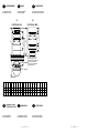

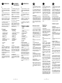

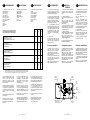


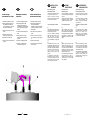

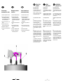


![Bedienungsanleitung Ha-Lo 32 A elektrisc[...]](http://vs1.manualzilla.com/store/data/006733480_1-8b207dd64bf6dc1fe51cd19e627ef7cc-150x150.png)