1
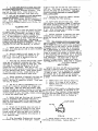
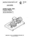
!NSTRUCTlONS
A N D P A R T S LIST
FORM:306-704
10 GALLON PRESIDENT HYDRA-SPRAY UNITS
STATIONARY
MODEL
LESS WHEELS AND BRAKE
WlTN MANUAL ELEVATOR
226-161 SERIES"A"
HAS MANIFOLD
WITH DUMP VALVE
PORTABLE MODELS
WITH MANUAL ELEVATOR
226-163 SERIES'A"
HAS MAHIrOLD
WITH DUMP VALVE
WITH PHCUMATIC ELEVPITOR
226-165 SERIES"6' 226-167 SERIES"A"
HAS FILTER
WlTN DUMP VALVE
PNEUMATIC
ELEVATOR
TIP OF
CUSTOMERS CHOLCE
ILLUSTRATED
TIP OF
CUSTOMERS CHOICE
\
..
ILLUSTRATED
DESCRIPTION
These Hdi-a-Sorav Units aoulv l i e h t materi+Is by u t i l i &
HkH-HYDilAULIC' &SS&
TwtOuGH
A SMALL FLUID CEIFICE. The cmbination of hich
fluid pressure and s m a l l o r i f i c e c r e a t e s f i n e material breakup without atomizing a i r . This
a i r l e s s Spraying system without heatwas o r i g i n a l l y pioneered and developed by Graco e n s b e e r s
t o improve the consistency and lower t h e c o s t s
of coating applications. The portable, truckmounted HydraSpray unitswheel d i r e c t l y t o t h e
work, viterever the job site ...inplant or outs i d e , on r o q h t e r r a i n or in a remote area.
Works d i r e c t from o r i g i n a l 1 t o 10 gallon containers. Rovides fast color changing f o r short
run work, quick mobility for constantone-color
application.
Units u t u i z e a i r p r e s s u r e t o (1) operate
the pump wllich powers the transfer of material
to the sprayt i p , ( 2 ) drive the agitator that
thoroughly mixes and keeps material solids in
s g a y a b l e suspension and (3) pomr the pneumatic elevator, of Xodels 226-165 and 2.26-167,
for f a s t , easy material containerchanging. No
a i r used t o atomise the material...no pressure
on container...no possible aeration of material.
Special, air-powered, reciprocatinp type pump
HAS FILTER WITH DUMP
VALVE AND SURGE TANK
provides continuous-duty action, . 4 t h equal ?ressure and volume deliver7 on both strokes. amp
develops material pressure 28 times greater than
t h e inbound a i r pressure. (For example: a t 60 PS:
inbound a i r , t h e pump develops 1680 PSI material
pressure.)
Units are desigedfor hiqh volume,~production-type spraying of protective coating paints
and similar l i g h t n a t e r i a l s , p r o v i d i n sa heavy,
one coat application with almostcomplete elimination of overspray. Al units a r e equipped w i t h
a material outlet manifold havins a valve,for rec i r c u l a t i n g material or dumping sludge. .Also
manifold has an extra material outlet f o r addition
of a second spray
Models 226-165 and 226-167
include a f i l t e r k i t , shipped loose, which can be
e a S u y i n s t a l l e d i nmanifold t o f i l t e r t h e materiAlso Model 226-167 includes a surge tank,
shipped loose, that can be e a s i l y assembled t o
manifold to eliminate material surge. NOTE: A
tungsten carbide spray t i p of customers choice i s
included i n a l l units. The proper spray t i p t o be
used f o r a specific material shouldbe determined
by a t e s t conducted by your l o c a l Graco I n d u s t r i a l
Distributor o r by h i s recommendation from previous
experience with thesame o r similar material.
al.
qm.
MODEL 226-161 SERIES " A "
MODEL 2 2 6 - 1 6 5 SERIES " A "
MOOEL 226-167 SERIES " A "
(STATIONARY LESS WHEELS AND BRAKE)
MODEL 226- 163 SERIES "A"
(WITH MANUAL ELEVATOR)
(WITH PNEUMATIC ELEVATOR)
164-700
157-367
101-160
202-3
,a
./a 3''N.RT.
202-338'
-157-245
-157-241
nc101-021
202-338
b l R LINE PETCOCK
I
205 -301
AGITATOR
AIR
BLOWER VALVE
157557
204-978
204-940
162-746
STRbIGHT SWIVEL
AIR LINE COUPLER
2
.
205-306
STRAINER
I
I
I
I
I
205-332
I
TRUCK
AND
ELEVATOR
GROUP
3
205-476
SURGE
TANK
F O R M O D E L
226-167
<SHIPPED LOOSE\
. ..
AIR REQUIREMENTS
T h i s equipment has been carefully manufacA i r p r e s s u r e s r e q u i r e d t o o w r a tPem P range
tured to exactingGRACO standards. It i s WWranted against defective materials and/or uork- from
x ) t o 1oo.s.i.
CAUTION: Do not use more
manship as set f o r t h in the GRACO WARRANTT.
than 100 lb. of a i r Dressure t o ODerate
Excessive wear due t o passage of abrasive or
corrosive materials through this equipment s h a l l
h - i n g continuous operation, a t n o d m-knot be construed as indication of defective parts ing pressures and operating speeds. this d t
within the limitationsof this warranty. require actual
a i r d e l i v e r y o f a p p r o x h a t e wh
c.f.m. per gun plus 3 c.f.m. for continuous use of
agitator.
IMPORTANT NOTES
PWP.
"PTFE materkl hose is expensive. HANDLE
To provide reserve capacity forpeak load
WPPH CARE. GRACO WARRANTI does not cover abuse conditions compressor should delivery 25% m e air
than required for normal operation Of all equipsuch as sharp khking, crimping or crushing.
ment which it is to serve.
Air supply hose 205-216 Includes a static
N&:
Consumtion of compressed a i r is lm,
h i r e t o e f f e c t i v e l yground the unit. If addisince in t h i s Hvdra-Sorap process a i r is not needt i o n a l a i r supply hose i s required, it should
ed t o atomize the paint.
be of the sane type.
PREPARATION FOR OPERATION
1. Remove contents
arton and cokzct before reaching unit.
NOTE: A Graco air line
the hire-braided h p o n t "PTFE l i n e d material
strainer 2OL-999 (accessory) may be purchased
hose 205-349 (15') or 204-938 (25' ) to nipple separately for
removing foreign matter from a i r
164-672 protruding from m a t e r i a l o u t l e t manifold entering
t h e unit. Attaches to a i r manifold
205-485. Connect t h e end, without swivel 2QL-9LO
162-376 a s shorn in Fig. 2.
attached, to nipple164-672. See Fig. 1. DO NOT
connect swivel 204-940, attached to other end of
205-216-- I e' NBT
*THESE ARC bCCtSSCUIU
2
t h i s hose, t o s p r a y gun a t this time. DO NOT U S E
THREAD S
E
M AT ANY WIVF,L CONNECTION.
NOTE: Check dump valve of manifold 205-485
...
it should be closed. When closed, its knob
is in a h o r i z o n t i l p o s i t i o n . R e f e r t o Fig. 1.
NOTE: Models 226-163. 226-165 & 226-167 are
equipped with a brake-to s e t b r a k e s push down
v i t h f o o t on rod protruding from bracket attached
t o back of truck base and guide rod into notch a t
bottom of bracket.
2. For operation of a second sprav mn
purchase these accessories separately...two ( 2 )
h i g h pressure material shutoff valves 205-583.
~. . .~
a second hose 205-349 (15') o r 2OL-938 (25'), a
L. If Model 226-161 o r 226-163 with handsecond swivel 2OL-940, a second spray e p 205-162
merated elevator, lift up on elevator hanger and
and a second s p r a y t i p of customers choice. Rehook over handle. NOTE: If elevator is d i f f i c u l t
move nipple 16L-672 and plug from manFfold
t o r a i s e , a p p l ya l i t t l e g r e a s e t o e x t e r i o rsurM5-485, and. qonnect
valves and hoses as shorn faces
of handle ends.
.
in Fig. 2.
If Model 226-165 or 226-167 with air-operated
3. Attaah one end of 15 f o o t a i r supply hose elevator, disconnect air line coupler 202-417,
205-216 t o s m c e of a i r Supply and screw other attached
t o end of a i r hose 160-023, from a b l i n e
end Of hose i n t o a i r manifold s w i v e l a d a p t e r f i t t i n g
in a g i t a t o r 205-307 and connect t o a i r
162-376.' Refer to Fig. 1. Kale hose studs are line fitting
157-367.atop e l e v a t o r a s shown in Fix.
threaded
NET.
I n s t a l l a master a i r valve
1. With a i r a d m i t t e d t o u n i t , e l e v a t o r w i l l r a i s e
(drain or bleed typelin the air supply
line in
u n i t and hold it t h e r e u n t i l a i hose
r
160621 i s
Snch location t h a t a i r can be turned on and off
disconnected.
4
should be used w i t h spray t i p s havin$ larger orif i c e openings.
5 . Remove from base the 10 qallon pail provided. Wipe clean i t s i n t e r i o r and pour <ntO it
m a t e r i a l s t i r r e d and thinned t o the proper spray
consistency o r place a smaller container of material i n s i d e t h e 10 g a l l o n p a i l . S t i r m a t e r i a l
thoroughly making sure there i s no heavy pigcent
concentration or cake formed on the bottom of the
container. The pigments must be well dispersed t o
prevent them from clogging the f l u i d intake
s t r a i n e r 205-306 when t h e pump i s i n i t i a l l y lowered into the container of material.
7. Lower pump i n t o material. If u n i t with
manual elevator, unhook hanger t o lower.
w i t h Dneumatic elevator, loner by disconnecting
a i r hose 160-023 from e l e v a t o r a i r l i n e f i t t i n g .
Refer t o F i g . 1.
NOTE: F a a small container, such as a one
gallon can. the material intake strainermust be
removed in order to get the lower pump housing and
the agitator propellor into the container.
6. Check the position of Poot valve feet in
r e l a t i o n t o the perforated plate162-363 of pump
fluid i n t a k e s t r a i n e r . When t h e p l a t e and screen
are held in position by t h e r e t a i n i n g r i n g162-Ll6,
t h e f e e t of foot valve body must contact and SUpport the perforated p l a t s 162-361 a s s h o w in
Fig. 3.
PUMP FOOT
NOTE: The speed a t which unit i s elevated,
b v a i r , is set a t factory. If adjustment is
necessary, loosen lock nut of air r e s t r i c t o r
valve 203-743 and t u r n r e e t r i c t o r screw'cloclcwise
to decrease or p g ~ e ~ c ~ o & + . ~ e&rcase.
to
Lock
screw in place with lock nut when adjustment is
completed. A i r r e s t r i c t o r v a l v e 203-743 i s located atop elevator tube. Refer to Fig. 1.
8. If u n i t i n c l u d e s a f i l t e r k 205-521
it
or
a f i l t e r k i t205-523 and a surqe tank 205-476,
r e f e r t o i l l u s.~
t r a t e dinrt.ruetions -~
in senarate
~.
'~~
Form 306-696 f o r easy conversion of manifold
205485 t o a f i l t e ror a filter-surp chkaher.
~"
9. I n s e r t d e l i v e r y end of material dispensing hose into a waste container. Startpump by
opening ON-OFT pump a i r petcock 202-338 and sett i n g r e g u l a t o r 205-360 a t 30 p.s.i.
Refer Fie 1.
Allow pump t o o p e r a t e u n t i l a l l t r a cof
e s rust
i n h i b i t i n g oil, with which pump was treated, is
removed. Stop pump and discard.materia1 pumped.
NOTE: If accessories have been added t o
unit f o r two gun operation, open material shutoff
valves 205-583 and insert ends of both hoses into
waste container before startingpump. Refer t o
Fin.
.- 2.
FIG.3
NCrPE: If desired, the 100 mesh screen in
s t r a i n e r 205-306 can be removed and reulaced w i t h
the extra, more coarse 50 mesh screen i62-746 supplied. Refer to Fig.
- 3. This 50 mesh screen
10. Connect swivel 204-940, a t t a c h e d t o f r e e
end of material dispensins hose; t o spray gun
inlet ,
OPERATION
IMPORTANT N O T E S
1. For most s a t i s f a c t o r y o p e r a t i n g condit i o n s , l o c a t e pump and material so t h a t t h e v rrill
not be sub,iected to temperatures below 65" F.
2. Do no.t attemut to surav materialscontaininq h e a w f i l l e r s . d i r t or other coame
5.. Dailv or more often if emerience Ldip a r t i c l e s . Coarse gsind, coagulated, contaminat- cates necessary, WITH PLMP DEACTIVATED AND FILTER
ed and skinned materials t h a t vill not pass freely "P VAL'? OmN TO RELEEVE M A T E R I A L PRESSRE, rethrough the openings in size of screen or filters move and c l e a n f i l t e r c a r t r i d g eo r screen, if
being used, without clogging, can not be s a t i s used. Refer t o Fig. 1.
f a c t o r i l y sprayed. Due t o the extremely s m a l l
OrVice diameter in spray tip throughwhich ma6.
remove and clean screen in pump
terial must be forced under pressure, it is very
material i n t a k e s t r a i n e r 205-306. men replacing,
important t h a t p a r t i c l e ' s which could plug t h i s
check t o be sure t h a t p l a t e 162-363 i s in contact
orifice are not presentin t h e m a t e r i a l t o be
w i t h f e e t of pump foot valve. Refer to Fig. 3.
Sprayed.
7. When thinning materia1;cleaning filters,
3.
b e f o r e s t a r t i n g t o s p r a yremove
,
screen, tips, etc.; changing types of material to
and c l e a n f i l t e r , if used, of spray
be sprayed or flushing unit; be sure to we CLEAW
solvent of a t w e rec&mended bv manufacturer Of
4.
wit> a i r p r e s s u r e s h u t o f f and
material beme snrayed. Use of the wrong solvent
relieved, remove and clean screen in air l i n e
may cause jellinn or separation of material compos t r a i n e r 20L-959 (accessol-g), if used. Add
ents which-could-cause clogging o f s t r a i n e r ,
l i g h t o i l t o screen cavity in s t r a i n e r n u t . See
f i l t e r and spray p n t i p . W NOT USE COMMCN CLW
Fig. 4.
CLEA"JER.
w,
Dap
li ,
&l~,
gun.
5
air pressure. Do not set hieher than
Nm: If manufacturer of material does not re- inbound
100 0.s.i.
0-nd
a specific type of solvent, check the coma t a b i l i t y of the solvent to.be usedf o r t h i n n i n g
5. While spraying be sure a t all t i m e s t o
he material by dropping a single drop o f t h e materihold spray gun perpendicular (approx. 9 0 " ) t o
1 i n t o a small container of ".he solvent. If the
laterial drop cloudsor disperses readily, the sol- surface to be sprayed, with i t s spray t i p 12 t o
U inches from surface or greater if the material
.ent is compatible. If d r o p t e n d s t o s t r i n gor
spray will cover s a t i s f a c t o r i l g . NOTE: Good
'orm a ball, the solventi s not compatible and
Hydra-Spray technique i s very similar t o con. e f i n i t e l y should not be used.
ventional spraying with air, exceptf o r the
AGITATION OF MATERIAL
from
greater distance spray tip should be held
work surface, the larger coatinq t h i c h s s proThorouah a g i t a t i o n of material should be
duced which r e s u l t s in less pattern overlapping
lccomolished p r i o r t o ~ u m p i n nm a t e r i a l t o s o r a y
and t h e p o s i t i v e a c t i o nused when t r i g g e r i n g gun.
E . Agitation can b e s t be obtained as follows:
NOTE: Refer t o t h e SERVTCE DIAGNOSIS CHART
1. Snap a i r line coupler 202437 onto agii n t h i s I n s t r u c t i o nSheet f o r assistance in 10;ator a i r f i t t i n g and a g i t a t o r WFU be energized.
cating troubles which may occur during spraying.
l e f e r t o Fig. 1.
Also refer to separate Instruction Sheetsf o r
spec'ific information pertaining to the spraygun,
2. W n agitator a i r valve x)5-528, t'm o r
pump, regulator and manifold o r f i l t e r .
nore t u r n s t o t h e l e f t start
to
agitator air
notor. Refer t o Fig. 1. Speed of a g i t a t i o n
nay be a d j u s t e d t o suit t h e p a r t i c u l a r v i s c o s i t y
SAFETY PRECAUTIONS
,P material used. N.WTE: Excessive agitation
speed may cause vibration and foaming of material.
The Hydra-Spray equipment develops extremely
h e moderate agitation speeds a t all times.
high material pressure which remains i n the system
u n t i l r e l i e v e d by shutting off the a i r t o pump
3. Open manifold dump valve and start pump. and releasing the material pressureby opening
This permits pump c i r c u l a t e t h e m a t e r i a lunder
manifold dump valve. In operation, if t h e f i n e
l i g h t load.
high pressure streamof material released from
spray gun i s allowed t o come in d i r e c t c o n t a c t
1. L i f t hinped inspection plate and examine with the hand or any p a r t of human body it could
progress of agitaiion through h i e in cover. It
penetrate the skin and cause physical harm.
i s extremely important t h a t all s o l i d s a r e D U t in
suspension and held there dbring the entire spray
HANDLE THE HYDFA-SPRAY GUN AS CAUTIOUSLY AS
operation.
YOU WULU ANYGUN: LOOR UNLOADED. The following safety precautions should be observed:
5. Allow a g i t a t o r t o c o n t i n u a o p e r a t i o n
h i l e u n i t is supplying material t o spray
point gun d i r e c t l y a t t h e f a c e .
a
gun.
-
SUPPLYING MATERtAL TO GUN
Nevar p u t t h e hand o r f i n g e r s d i r e c t l y over
the spray tip. (Use of protective leather gloves
i s recommended.)
1. Stop pump and close manifold dump valve
.fter material hasbeen c i r c u l a t e d s u f f i c i e n t l y
nd before attempting t o spray. When closed,
nob of dump valve is in a horizontal position.
Never place t h e t i p o r gun nozzle directly
in contact withany p a r t of the body.
2. @en material shutoff valves 205-583
accessory), if used. Handles a r e p a r a l l e l t o
.alve body when open. Refer t o Fig. 2.
shut off a i r p r e s s u r e t opump and relieve material pressurein system before attempting t o remove gun t i p o r screen and/or removing
gun f o r service.
open ON-OFF pump a i r control petcock
With petcock open, m i f o l d dumu valve
:losed and air regulator 205-360 s e t t o c o n t r o l
.he a i r pressure admitted, the pumping action of
mmp i s controlled by operation of spray
iqueezing t r i g g e r of spray gun open automatically
itarts pump operating, forcing material, under
r e s s u r e , from gun spray tip.
3.
92-38.
4.
aremove t i p from gun t o c l e a n it.
atighten threaded connections care-
gun.
f u l l y and securely, and handle hose carefully to
prevent leaks t h a t could cause physical harm same
as pressurized stream C O D ~ Qfiom o r i f i c e in gun
tip.
Adjust pump to pressure required
;o obtain desired breakup and spray pattern of
naterial. This s e t t i n g will vary due t o v i s c o s i t y
naterial,orFfice diameter and fan angle of spray
;ip. TO i n c r e a s e a i r p r e s s u r e tpump,
o
t u r n adjusting knob of regulator 205-360 c l o c M s e and
:o iecrgaze pressure turn it gagniegc&o+&e.
JOTE:
The amount of air pressure supplied t o t h e
1ump determines t h e pressure of the material
'orced through the orifice in spray tip. Pmp
levelops material pressure 28 times t h a t of the
6
Always be sure that the equipment supplying
t h e m a t e r i a l ' t o s p r a ygun is properly grounded
to prevent sparking. The high velocity f l o w of
material through the spray tip
may cause s t a t i c
e l e c t r i c i t y t o b developed.
e
Use only metal
b r a i d material dispensing hoses or s t a t i c protected hose. Also be sure to provide f o r t h e
proper grounding out of the compressor.
. .
PREVENTIVE MAINTENANCE
f i l t e r c a r t r i d g e o r screen, if used. Close
valve.
A t l e a s t t w i c e d a i l yand durine any lenethy:
interruption of sprayinq, with material pressure
relieved: remove and clean gun spray t i p and t i p
f i l t e r in clean solvent of a type recommended by
manufacturer
of the material beine
Blow
~.
_ smayed.
. .
p a r t s dry with a i r pressure. Also k e r s e gun
nozzle in clean solvent during shut down periods.
~
~
gun.
3 . Remove spray t i p and f i l t e r , i f used,
Immerse in clean recornended
ir'om spray
type solvent and wash thoroughly with a fine
b r i s t l e d b r u s h . Using t h e a i r blower valve
205-541 a t t a c h e d t o a i manifold
r
162-376, blov
a i r through t i p from f r o n t t o back and through
open end of filter. Refer to Fig. 1. Keep
spray gun forward end submerged in && recotmuended type
.. solvent u n t i l r e a d y t o start
spraying again. NOTE: Do not remove t h e s w a q
e m from dispensine hose unless the uniti s t o be
completely flushed. Keeping unit f u l l y charged
with material will minimize~thenecessity for
flushing u n i t .
~~
SHUTDOWN PROCEDURE
To maintain e f f i c i e n t o p e r a t i o n of u n i t ,
t h e completion of
each day's spraying must be d i l i g e n t l y followed:
t h i s shutdown procedure a t
1. Shut o f f a i r t opump by closing pump
ON-OFF a i r control petcock 202-338.
See Fig. 1.
to
body when
Handle is a t r i g h t a n g l e petcock
closed.
2. Relieve material pressure in
pump, hose
and spray gun by opening drump valve of -ifold.
This will a l l o w the material trapped in thesystem
t o drain back into material container. After mat e r i a l has stopped draining, remwe and clean
-SERVICE
drain
m:
,
Water based p a i n t s w i l l r e q u k e a
final flushing with solventDAILY and a l s o O i l i n g
of a l l e x t e r n a lmoving pump p a r t s to prevent the
rusting of the wetted parts. To completely flush
u n i t follow the procedure outlined in subsequent
paragraph e n t i t l e d FLUSHINC UNIT.
DIAGNOSIS
CHECK POINT NOS.
TROUBLESOME sIMPpOM.5
.............
.............................
..........................
.......................
..........................
............................
Fump fails t o o p e r a t e , no material discharge.
Pump operates, but insufficient material discharge.......
Excessive surge a t spray gun
I n s u f f i c i e n t m a t e r i a l breakup..
T a i l s in spray pattern............
Spray gun spitting.............
Too heavy a coating thic.ess
mssmm CAUSES
CHECK POINT NO.
1-3-4-6-6-9
2-4-7-Y,
1-2-9-10-12
1-2-3-4-6-9-11
1-24-6-ll
13
5-10-11
Restricted ak. supply line.
Insufficient air capacity.
........
Air valve closed or clogged.
3....
l........
-
2
L........
A i r regulator inoperative or s e t t o o low.
A i r r e g l l a t o r s e t t o ohigh.
Material too viscous
I n s u f f i c i e n t material in container.
Clogged m a t e r i d i n t a k e s t r a i n e r .
Clogged m a t e r i a l f i l t e r , t i por t i p f i l t e r .
Hish flow rate-tip orifice too large.
Improper or worn spray gun t i p .
Surge chamber inactive, if used.
Worn, damaged o r obstructed gun parts.
Worn o r obstructed pump valves or packings.
........
5........
6
7........
e........
9........
lo........
ll........
12........
l?........
U......,.
MAINTENANCE
IMPORTANT NOTES
and relieve material pressure in system by opening
dump valve of manifold or f i l t e r .
1. Keev u n i t , mixine container. thinner,
solvent. and material CLEAV and f r e e of foreisn
p a r t i c l e s r b i c h could clog strainer screens andl
o r plug the small orificein spray tip.
4. Daily or more often if experience indicates necessar , d r a i n f i l t e r o r surge tank, remore filter cart:idne
or screen. if used, and
2. Keep lower vump Assembl-f f i l l e d n i t h
and s m a v mn head immersed in recommended type
clean s o l v e n t a f t e r f l u s h i n 4 u n i t and u n t i l
r e a d y t o start sprayine again.
-3. TO r e l i i v e - u n i t Of unnecessary pressure
when not in use, shutoff a i r p r e s s u r e t opump
~
and close dump valve.
7
.
. . . . . . . . . . . . . . . . . . . .
t r i g g e r of spray
and open a i r line petcock to
s t a r t pump. Allow
pump to operate longenough to
as often as experience indicates necessary. Stop fill hose and spray q n with solvent. ~~~p u n i t
pump and open dump valve. After material has
filled with solvent OVerniQht or breekend u n t i l
readv t o soray aeain.
drained completely from tank, close dump valve.
6. Shut off a i r p r e s s u r e t o u n and
it relieve
9. Eecirculate solvent for about 5 minutes
cressure in a i r l i n e , b e f o r eremovins screen
156-967 in a i r line s t r a i n e r 20k-999 (accessory i f
P i o r t o c h a r & % a nwith
i t material.
llsed). Daily, clean t h i s s c r e e n and a t reassembly
edd l i g h t o i l t o s c r e e n c a v i it n
y nut 156-944. Re10. Close Spray gun and r a i s e pump. S t a r t
operating, by squeezing trigger of spray gun
f e r t oFig. L.
and continue ooeratinn untilmost of solvent has
been blown o u t of sysiem. Drain excess solvent
FLUSHING UNIT
from loops in hose and f n t e r or surge chamber.
The frequency vithwhich unit should be flush- if used. After draining tankof filier or s u r &
ed deoends upon type o r types of m a t e r i a l pumped,
chamber, close i t s dump valve.
generil operating conditions,and usage of u n i t .
11. Replace container of material upon base,
It is wi5e t o e s t a b l i s h a re&= flushing scheUlower
pump into container, connect a i r hose t o
ule. In some instances it may be d e s i r a b l e t o
f l u s h u n i t d a i l v w h i lin
e other cases less freouenta g i t a t o r and charge unit with properly mixed
material.
flushing may prbve s a t i s f a c t o r y . u n i t m u s t 2
flushed at the end of each wurkine week. ThoroughNOTE: When chansins colors or incompatible
17 flush unit with thinner o r solvent of type ret m e s of material, flush unit as described, HOWcommended for use with the material,as follows:
EVER, a lonaer circulation oeriodw
l
l
i
necessarilv
be required-and in some casks a second flushing
1. Remove Spray t i p and glm f i l t e r cartridge,
using thinner oi'solvent
may be necessary.
if used, from spray Sun and soak in clean recommend- Also if manufacturer of another typeof material
ed .type solvent.
t o be sprayed recommends u s i n s a d i f f e r e n t t r p e of
thinner or solvent, the thinner or solvent used in
2. With air SUPPlY to unitturned On, dist h e first flushing must be flushed out to eliminate
connect a k ' h o s e t o a g i t a t oand
r connect it t o
t h e p o s s i b i l i t y of separation or j e l l i n g of mae l e v a t o r t o r a i s e u n ior
t manually r a i s e and
t e r i a l components. The sur3e tank or tank of
hook hanger over truck ha.ndle. manifold
or f i l t e r should be removed and par.ts
thoroughly scrubbed clean. Surge tank is equipped
3. With P m P a i r petcock 202-338 open, d i r e c t Tvith a removable plur:
to facilitate
cleaning.
spray gun i n t o material container and start pump
operatink by squeezing trigger of spray
Unit
AGITATOR
r r i l l pump a i r , f o r c i n g t h e m a t e r i a l o of
ut the
system back into container. When t h e a i r has Agitator
a i r motor 101-687 m u s t be properly
o i l , whenever
flushed Out as much Daterial as possible, StopPump ofled with a l i g h t a i r motor
and open manifold dump valve. Drain excess materi- is shutdorm or is not to
be operated for a period
a1 from all loops i n hose. After material has
Of 8 hours or more.
A
l compressed a i r oontains
stopped draining, close manifold dump valve.
some moisture and if a i r motor i s not nrouerlv
lubricated before shutdown, rust may result." To
L. Remove container of material from base and oil motor:
position in i t s d a c e a pail containine. approximately 2 gallons' of comGtible solvent: Loxer pump
1. Remove o i l e r screw from a i r motor top.
i n t o p a i l of solvent.
2. Apply 3 t o L droos of o i l t o o i l e r .
3. Replace o i l e r screw and run motor for
5 . S e t a i r t opump a t a p p r o x h a t e l y20 p.s.i.,
about 1/2 minute.
d i r e c t gun t o m a t e r i a l c o n t a i n e rand t r i g g e r gun
t o start pump. Runp will move the solvent, under
A i r motor should require no attention other
pressure through the system, flushing the internal than t o be oiled. However, i f t o o heavy an o i l
c a v i t i e s o f manifold and f i l t e r o r surge tank. When has been used o r o t h e r improper o i l i n g p r a c t i c e s
solvent appears a t gun, s t o p pump, release pressure have been followed guming of rotor may r e s u l t ,
in system and remove spray ppn.
imwhich case air motor should be flushed as
follows:
6 . Remove spray gun from hose and thorou5hly
clean in accordance with procedure outlined i n
gun. Keep
separate Instruction Sheet for the spray
OILER SCREW
spray gun head immersed in solvent until attached
t o hose again.
161-41
5. If suree tank 205-L76 i s beine used withoutf i l t e r D a r t s i n s t a l l e d , it should be drained
'
g
u
n
,
~
~~
~~
~~
~~
~~~~~
-
-
gun.
~
7. Direct end of material hose into pailof
solvent and start pump by opening a i r l i n epetcock
202-338. A l l o w thinner o r s o l v e n t t o c i r c u l a t e
through system and back i n t o p a i l f o r a period of
10 t o 1 5 minutes. Wash material from e x t e r i o r of
lower immersion pump.
8. After thoroughly flushing u n i t s t o p pump
Squeeze
aP.d connect material hose t o s p r a y
gun.
FIG. 5
a
~
.~. - ~ ~
1. Remove exhaust muffler 161-415. F i l l t o
overflowing with kerosene. ~~~l~~~
muffler.
.,
'
,
>
.
2. Remove oiler from air motor topcap. See
Pig.
. 5. Fill oiler with kerosene. Replace oiler.
3. dllow a soaking period of,5 to 10 minutes,
then starta b motor. Run motor slowly. After
smooth operationhas been achieved and kerosene has
been blown from a*haUSt. stop L
U
O
O
tr
, remove o u e r
air motor oil.
screw and fFu oiler with a light
NOTE:
.
NO ATPMPT M DIS AS S MBLB ADl
should need
repab, contact pour
nearest Graco Authorized %mice Depot.
MAgE
.
fIG.6
MUa
'l. If it
ELEVATOR
FLUID SHUTOFF VALVE
LUERICATION
205-583 (ACCESSORY\
Every 2 to 6 weeks with elevator freeof air
pressure, unscrew and remove cap &-ab. Fill
inner carityof cup leather150-179 vith SdE 20
oil. Replace cap. Raise elevator and lubricate
exposed surface of elevator guide 1&-7A7.
tube
See parts illustration
for location of parts.
Worn "0" rings, b a l l seat or b a l l may cause
valve to failto operate. If sesvice is necessary,
shut offair supply, relieve fluid pressure and remove valve. Place valvebody in a vise and drive
the two pina outof holes in valve body. Runwe
valve cap from body being careful not to turn cap
as this would shearoff the locating pins in valve
body. See Fig. 6. Disassemble andreplace any
worn or damaged parts. NOTE: W i t h handle removed,
"On ring 15L,-7lJ can be best removedby first removing b a l l 162-831. from body and then pushing
handle shaft downintb cavity in valve body'.
PUMP. REGULATOR, S P R A Y GUN AND
FILTER OR SURGE CHAMBER
Refer to separate sheetfor maintenance instructions and parts identification.
REPAIRING HYDRA-SPRAY HOSE
dra-Spray hoseis constructed oftiupont
"PTFE inner lining tube with stainlesssteal
wire braid Outer CWer. This hose is exoensive
and shouldbe handled withcare. If hose should
becane damaged it can be salvaged by assembling
Couplings to t h e broken ends of hose sections.
Graco detachable and reusable couplings consist
Of two parts. the female M v e l stud 201.-937 and
the sleeve 162-366. and are assembledupon hose .
in the followingmanner:
3. Add a dropof oil to the endof the
t
I groovad
vires, position assembly.block viths
side towardend of hosejust cut and
slide block
onto hoseuntil it protrudes about1/32 to 1/16
of hose. See Fig. 8.
of an inch beyond the end
ASSEMW
moL
or rmrunc
.
no. F-20198
CIUIIONDO NOT CRUSH
HO5L
~
NUTE: A hose coupling fixture Graco No.
F-20898 specifically designedto facilitate the
assembly ofcouplbgs upon this tppe of hosemay
be obtained from factory. This fixture consists
of a thu piece assembly
block and an assembly
tool as shown in Fig.
. 7, 8 and 9.
4. a p
Position the two piece assemblyblock on. ,jvW ass&ly
hose With plain sideof block toward hose end to holdingblock
be cut and clamp in a d s e as shown in Fig. 7.
into hose and
Cut off With a fine
tooth hand hack saw.
1.
2. Remove hose from block and grip In vise
about 2 inches from end just cut. CAUTION: 00
not crush the hose-apply o n l y enough pressure
on the viae jaws to hold while forcing the sleeve
onto hose.
9
the threadede.nd of sleeve 162-366
twl as shown in Fig. 8 and while
in placeon hose, insert end of
tool
end ofsleeve intogroove.
5. While twisting sleeve back and forth
vith awrench apply body pressure to assembly
allow
t d and as sleeve is forced onto hose
block to slide back. After about & inch Of
hose is covered, remove the block and continue
to force sleeve ontothe hose until end of hose
reaches the shoulder in sleeve. Refer to
Fig. 10.