1
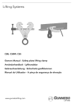
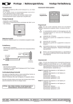
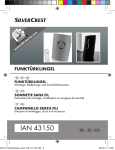
I
FAR Rubinetterie S.p.A. - www.far.eu
SERVOCOMANDO “SMALL”
Art.3001- 3002- 3005- 3006-3007-3008
3. COLLEGAMENTI ELETTRICI
Prima di collegare elettricamente il servocomando accertarsi che il modello prescelto sia compatibile con la tensione di rete disponibile.
Tutti i collegamenti devono essere effettuati da personale specializzato rispettando lo schema elettrico (riportato anche sul servocomando)
ed accertandosi che la linea elettrica non sia sotto tensione. Allacciamenti errati possono provocare danni sia alle persone sia al
servocomando.Tutte le versioni sono predisposte con microinterruttore ausiliario supplementare, ossia con contatti di scambio senza
tensione, a disposizione dell’utente per segnali a bassa tensione (max 230 V) e/o per alimentare utenze a basso assorbimento (max 2A).
ISTRUZIONI PER L’USO
Il servocomando è a doppio isolamento per cui non necessita della messa a terra.
COLLEGAMENTO A 3 FILI: COMANDO CON TERMOSTATO AMBIENTE
230 V
230 V
24 V
24 V
ART.3005 20
ART.3005 40
ART.3006 20
ART.3006 40
230 V
230 V
24 V
24 V
ART.3007 8 230 V
ART.3008 8 24 V
ARTICOLO
TENSIONE
FREQUENZA
POTENZA
ASSORBITA
ANGOLO DI
ROTAZIONE
TEMPO DI
ROTAZIONE
COPPIA
MOTRICE
TEMPERATURA
D’IMPIEGO
GRADO DI
PROTEZIONE
COLORE
3001 20
230 V-50Hz
4,5 VA
90°
20 S
6 Nm
-10° + 50°C
IP54
GIALLO
3001 40
230 V-50Hz
4,5 VA
90°
40 S
10 Nm
-10° + 50°C
IP54
GIALLO
3002 20
24 V-50Hz
4,5 VA
90°
20 S
6 Nm
-10° + 50°C
IP54
GIALLO
3002 40
24 V-50Hz
4,5 VA
90°
40 S
10 Nm
-10° + 50°C
IP54
GIALLO
3005 20
230 V-50Hz
4,5 VA
90°
20 S
6 Nm
-10° + 50°C
IP54
VERDE
3005 40
230 V-50Hz
4,5 VA
90°
40 S
10 Nm
-10° + 50°C
IP54
VERDE
3006 20
24 V-50Hz
4,5 VA
90°
20 S
6 Nm
-10° + 50°C
IP54
VERDE
3006 40
24 V-50Hz
4,5 VA
90°
40 S
10 Nm
-10° + 50°C
IP54
VERDE
3007 8
230 V-50Hz
8,5 VA
90°
8S
4 Nm
-10° + 50°C
IP54
GRIGIO
3008 8
24 V-50Hz
8,5 VA
90°
8S
4 Nm
-10° + 50°C
IP54
GRIGIO
COLLEGAMENTO A 5 FILI: COMANDO CON TERMOSTATO AMBIENTE E ACCENSIONE POMPA
La presenza del microinterruttore ausiliario (contatto pulito) interno
collegato ai cavi grigio e bianco, essendo indipendente dal circuito
del servocomando, permette l’allacciamento di più servocomandi in
parallelo per governare un’unica apparecchiatura come ad esempio la
pompa o la caldaia. Nel caso si debba comandare l’avviamento della
pompa già presente in caldaia, basta collegare i cavi di colore grigio
e bianco ai due morsetti predisposti (sulla caldaia) per l’allacciamento
al termostato.
MORSETTIERA INTERNA
Adatto per l’utilizzo in ambiente con forte polluzione
azione di tipo 1 C.D
1
1. DESCRIZIONE DEL SERVOCOMANDO
2
3
N
5
6
7
2. UTILIZZO DELLO SBLOCCO MANUALE
- Posizionare la valvola una volta installato il motore
- Mancanza di corrente elettrica
Per portare in apertura o in chiusura il motore
manualmente, tenere premuto il tasto di colore giallo
e contemporaneamente ruotare di 90° in senso
antiorario l’indicatore di posizione. Il ripristino del
funzionamento normale avviene automaticamente.
NERO
GRIGIO
- Interrompere il flusso d’acqua nel caso di interventi
straordinari sull’ impianto
MARRONE
Lo sblocco manuale può essere utilizzato per:
BLU
Il servocomando, costituito da un motoriduttore, permette la manovra di
una valvola di zona in modo completamente automatico, prelevando il
segnale per il suo azionamento da un termostato ambiente con regolazione
ON-OFF di tipo tradizionale, un cronotermostato o da un qualsiasi contatto
elettrico di apertura/chiusura. Tramite un indicatore è possibile conoscere
in che posizione si trova la valvola.
Per l’installazione controllare che il servocomando sia in posizione di
“APERTO” verificando che l’indicatore di posizione sia orientato nel senso
di moto del fluido. Predisporre la valvola in posizione di “APERTO” ossia
che il taglio a cacciavite sia orientato come il perno del servocomando.
Inserire i prigionieri negli appositi fori sulla flangia della valvola e bloccare
con i dadi forniti in dotazione. Il servocomando si può installare su tutte le
valvole di zona FAR. Non è adatto all’utilizzo in atmosfera esplosiva.
BIANCO
ART.3001 20
ART.3001 40
ART.3002 20
ART.3002 40
Per comandare l’apertura e la chiusura della valvola di zona per
mezzo del servocomando, basta collegare il cavo di colore blu al
neutro dell’alimentazione, il cavo di colore marrone alla fase ed il cavo
di colore nero al termostato ambiente. Con presenza di fase sul cavo
nero la valvola va in apertura.
Per il corretto funzionamento del servocomando è importante che il
cavo marrone sia sempre sottotensione.
COLLEGAMENTO
DESCRIZIONE
GRIGIO
COMUNE DEL MICROINT.
COLLEGATO AL COMUNE
MICROINTERRUTTORE AUSILIARIO
2
BIANCO
N.A. DEL MICROINT.
COLLEGATO AL NORMALMENTE APERTO
DEL MICROINTERRUTTORE AUSILIARIO
3
-
SPIE DI SEGNALAZIONE
CON VALVOLA APERTA
PRESENZA DI FASE SUL MORSETTO
NEUTRO
COLLEGAMENTO AL NEUTRO
FASE
COLLEGAMENTO ALLA FASE
APRE
CON FASE SUL NERO LA VALVOLA SI APRE
CHIUDE
IN ASSENZA DI FASE SUL NERO LA
VALVOLA SI CHIUDE
SPIE DI SEGNALAZIONE
CON VALVOLA CHIUSA PRESENZA DI
FASE SUL MORSETTO
N°
COLORE
1
N
BLU
5
MARRONE
6
NERO
7
-
DIRETTIVA 2002/96/CE SUI RIFIUTI DI APPARECCHIATURE ELETTRICHE ED ELETTRONICHE
La direttiva comunitaria 2002/96/CE sui RAEE (rifiuti di apparecchiature elettriche ed elettroniche) prevede che sia vietato
smaltire qualsiasi tipo di RAEE come rifiuto solido urbano ma debba essere obbligatoriamente gestito separatamente.
Per il corretto smaltimento dei RAEE occorre rivolgersi alle autorità locali che informeranno sulle modalità e procedure
da seguire, nonchè sul luogo e sugli orari per i quali dovrà essere conferito il rifiuto.
DADI DI FISSAGGIO
DICHIARAZIONE DI CONFORMITA’
La FAR Rubinetterie dichiara sotto la propria responsabilità che i servomotori sono conformi alle direttive comunitarie:
2004/108/CE e 2006/95/CE.
NON RIMUOVERE I
DUE DADI INDICATI
4. ASSISTENZA TECNICA
Per qualunque tipo di problema evitare di intervenire direttamente e contattare FAR Rubinetterie S.p.A . via Morena, 20 28024 GOZZANO
(NO) Tel. 0322/ 94722 - 956450 - FAX 0322-955332
VF073 EDIZIONE N° 4: 16/09/2010
D
FAR Rubinetterie S.p.A. - www.far.eu
STELLANTRIEB “SMALL”
MONTAGEANLEITUNG
Art.3001- 3002- 3005- 3006-3007-3008
3. ELEKTRISCHER ANSCHLUSS
Bevor die elektrische Verbindung vorgenommen wird, ist zu prüfen, ob der gewählte Stellantrieb mit der vorhandenen Netzspannung kompatibel
ist. Alle Verbindungen müssen von Fachleuten vorgenommen werden. Der Schaltplan (auch auf dem Stellantrieb selbst angegeben) muss
berücksichtigt werden. Das Strom muss unbedingt ausgeschaltet sein. Fehlerhafte Verbindungen können Schaden an Personen und an
den Stellantrieb selbst anrichten. Alle Modelle verfügen über einen Zusatz-Mikroschalter, d.h. einen spannungslosen Wechselkontakt, zur
Verbindung eines Signalgebers für die Niederspannung (max. 230V) und/oder für Benutzerkreise von geringer Absorption (max. 2A).
Der Stellantrieb ist doppelt isoliert, daher ist die Erdung nicht notwendig.
3-KABEL- VERBINDUNG: SCHALTUNG MIT RAUMTHERMOSTAT
PHASE
BRAUN
ART.3001 20
ART.3001 40
ART.3002 20
ART.3002 40
230 V
230 V
24 V
24 V
ART.3005 20
ART.3005 40
ART.3006 20
ART.3006 40
RAUMTHERMOSTAT
SCHWARZ
230 V
230 V
24 V
24 V
ART.3007 8 230 V
ART.3008 8 24 V
BLAU
Die Steuerung des Zonenventils durch den Stellantrieb erfolgt über die
Kabelverbindung mit dem Signalgeber. Das blaue Kabel wird mit dem
Neutralleiter verbunden, das braune und das schwarze Kabel werden
mit dem Raumthermostat verbunden. Führt das schwarze Kabel
Strom, wird das Ventil geöffnet. Wird das schwarze Kabel wieder
stromlos geschaltet, fährt das Ventil in die Ausgangsstellung zurück.
NEUTRALLEITER
ARTIKEL
SPANNUNG
STROMVERBRAUCH
DREHWINKEL
DREHZEIT
DREHMOMENT
RAUMTEMPERATUR
SCHUTZGRAD
FARBE
3001 20
230V-50HZ
4,5 VA
90°
20 S
6 NM
-10° + 50°C
IP54
GELB
3001 40
230V-50HZ
4,5 VA
90°
40 S
10 NM
-10° + 50°C
IP54
GELB
3002 20
24V-50HZ
4,5 VA
90°
20 S
6 NM
-10° + 50°C
IP54
GELB
3002 40
24V-50HZ
4,5 VA
90°
40 S
10 NM
-10° + 50°C
IP54
GELB
3005 20
230V-50HZ
4,5 VA
90°
20 S
6 NM
-10° + 50°C
IP54
GRÜN
3005 40
230V-50HZ
4,5 VA
90°
40 S
10 NM
-10° + 50°C
IP54
GRÜN
3006 20
24V-50HZ
4,5 VA
90°
20 S
6 NM
-10° + 50°C
IP54
GRÜN
3006 40
24V-50HZ
4,5 VA
90°
40 S
10 NM
-10° + 50°C
IP54
GRÜN
3007 8
230V-50HZ
8,5 VA
90°
8S
4 NM
-10° + 50°C
IP54
GRAU
3008 8
24V-50HZ
8,5 VA
90°
8S
4 NM
-10° + 50°C
IP54
GRAU
5-KABEL- VERBINDUNG: SCHALTUNG MIT RAUMTHERMOSTAT UND PUMPENSTEUERUNG
PHASE
PUMPE
BRAUN
WEISS
GRAU
RAUMTHERMOSTAT
SCHWARZ
BLAU
NEUTRALLEITER
N°
GRAU
2
WEISS
- um den Wasserfluss während Wartungsarbeiten zu
unterbrechen
3
-
- zur Kugelverstellung, wenn der Motor bereits installiert ist
N
BLAU
5
BRAUN
6
SCHWARZ
2. NUTZUNG DER HAND-NOTBETRIEB
1
2
3
N
5
6
BRAUN
SCHWARZ
Um den Motor in die gewünschte Position zu bringen, gelbe
Taste gedrückt halten und gleichzeitig die Stellungsanzeige,
mit der Antriebswelle verbunden, um 90° im.
Gegenuhrzeigersinn
drehen.
Die
normale
Wiederinbetriebnahme erfolgt automatisch.
BLAU
- bei Stromausfall.
GRAU
Die Hand-Notbetrieb wird genutzt:
WEISS
Der Stellantrieb mit Getriebemotor ermöglicht, ein Mischventil in völlig
automatischer Weise zu steuern. Das Auslösungssignal wird von einem
Thermostat oder einem ähnlichen Signalgeber mit "Ein-Aus"-Funktion
übernommen. Durch die Stellungsanzeige am Gehäuse lässt sich die
Stellung der Kugel ablesen.
Bevor Sie das Gerät installieren, prüfen Sie, ob der Antrieb in "offen"Stellung steht; Die Anzeige muss in die gleiche Richtung zeigen, in der
das Medium fließt. Der Schlitz im Spindelkopf des Gehäuses muss in der
gleichen Richtung wie der Zapfen des Motors ausgerichtet sein. Führen Sie
die Gewindebolzen in die Bohrungen des Flansches ein und ziehen Sie die
Muttern an. Der Antrieb kann mit allen Zonen-Ventilen kombiniert werden.
Achtung: kein Betrieb Der Einsatz in explosionsgefährdeten Umgebungen
ist nicht zulässig!
FARBE
1
INTERNE KLEMMENLEISTE
1. BESCHREIBUNG DES STELLANTRIEBS
Ein eingebauter Mikroschalter, mit dem grauen und dem weißen
Kabel verbunden (freien Kontakt), unabhängig von der Schaltung
des Stellantriebs, ermöglicht die Parallelschaltung von mehreren
Stellantrieben und somit ein einziges Gerät zu steuern (z.B., eine
Pumpe oder die Kesselregelung). Zur Auslösung der Pumpe,
verbinden Sie das graue und das weiße Kabel an die 2 Klemmen, die
am (Kessel) zum Anschluss an die Thermostate zur Verfügung stehen.
7
7
-
SCHALTUNG
BESCHREIBUNG
MIKROSCHALTER
VERBINDUNG MIT DEM ZUSATZMIKROSCHALTER
GEMEINSAMER KONTAKT
ÜBLICHERWEISE
OFFENER
MIKROSCHALTER
VERBUNDEN MIT DEM ÜBLICHERWEISE
OFFENEN ZUSATZ-MIKROSCHALTER
SIGNALANZEIGE
BEI GEÖFFNETEM VENTIL, STROM AN DER
KLEMME VORHANDEN
NEUTRAL
VERBINDUNG MIT DEM NEUTRALLEITER
PHASE
VERBINDUNG MIT PHASE
ÖFFNET
BEI STROM AN DER SCHWARZEN KLEMME,
VENTIL OFFEN
SCHLIEßT
OHNE STROM AN DER SCHWARZEN
KLEMME, VENTIL GESCHLOSSEN
SIGNALANZEIGE
BEI GESCHLOSSENEM VENTIL, STROM AN
DER KLEMME VORHANDEN
EU-RICHTLINIE 2002/96/EG BEZÜGLICH ABFALL VON ELEKTRISCHEN UND ELEKTRONISCHEN GERÄTEN
Nach der europäischen WEEE-Richtlinie 2002/96/EG (Abfall von elektrischen und elektronischen Geräten) ist eine
Entsorgung von allen WEEE Geräten als Hausmüll verboten. Die betreffenden Geräte sind getrennt zu entsorgen.
Für die einwandfreie Entsorgung der WEEE Geräte wenden Sie sich bitte an die zuständigen Behörden, die über das
betreffende Entsorgungsverfahren informieren. Bei Kauf eines neuen, identischen Geräts ist es zulässig, das Altgerät
zur Entsorgung dem Händler zu übergeben.
MUTTERN
BEIDE GEWINDEBOLZEN
NICHT ENTFERNEN!
KONFORMITÄTSERKLÄRUNG
FAR Rubinetterie erklärt unter eigener Verantwortung, dass der Stellantrieb der folgenden EU-Richtlinien entspricht:
2004/108/CE und 2006/95/CE.
4. KUNDENDIENST
Bei technischen Schwierigkeiten vermeiden Sie bitte jeden direkten Eingriff und setzen Sie sich mit der Fa. FAR Rubinetterie S.p.A. Via
Morena, 20 – 28024 Gozzano (NO) Tel. +39.0322.94722 – Fax +39.0322.955332 in Verbindung.
GB
FAR Rubinetterie S.p.A. - www.far.eu
“SMALL” ACTUATOR
Art.3001- 3002- 3005- 3006-3007-3008
3.ELECTRICAL CONNECTION
Before connecting the actuator ensure that the selected model is compatible with the available network voltage.
All connections must to be made by qualified personnel, with respect for the overall electrical system and taking care that the electricity
supply is switched off. Incorrect connection may damage both persons and equipment. All FAR actuators have been designed with an
additional auxiliary microswitch, an exchange contact without voltage, for low-tension signals (max. 230 V.) and/or to supply applications
with low electrical input (max 2A).
INSTRUCTIONS
The actuator is provided with a double isolation, so earthing is not required.
WIRING CONNECTIONS: ACTUATOR AND THERMOSTAT
PHASE
BROWN
ART.3001 20
ART.3001 40
ART.3002 20
ART.3002 40
230 V
230 V
24 V
24 V
ART.3005 20
ART.3005 40
ART.3006 20
ART.3006 40
ARTICLE
VOLTAGE
FREQUENCY
ABSORBED
POWER
R O TAT I O N
ANGLE
ROTATION
TIME
3001 20
230 V-50Hz
4,5 VA
90°
3001 40
230 V-50Hz
4,5 VA
3002 20
24 V-50Hz
3002 40
24 V-50Hz
3005 20
BLACK
230 V
230 V
24 V
24 V
ART.3007 8 230 V
ART.3008 8 24 V
BLUE
TORQUE
ROOM
TEMPERATURE
DEGREE OF
PROTECTION
COLOUR
20 S
6 Nm
-10° + 50°C
IP54
YELLOW
90°
40 S
10 Nm
-10° + 50°C
IP54
YELLOW
4,5 VA
90°
20 S
6 Nm
-10° + 50°C
IP54
YELLOW
4,5 VA
90°
40 S
10 Nm
-10° + 50°C
IP54
YELLOW
230 V-50Hz
4,5 VA
90°
20 S
6 Nm
-10° + 50°C
IP54
GREEN
3005 40
230 V-50Hz
4,5 VA
90°
40 S
10 Nm
-10° + 50°C
IP54
GREEN
3006 20
24 V-50Hz
4,5 VA
90°
20 S
6 Nm
-10° + 50°C
IP54
GREEN
3006 40
24 V-50Hz
4,5 VA
90°
40 S
10 Nm
-10° + 50°C
IP54
GREEN
3007 8
230 V-50Hz
8,5 VA
90°
8S
4 Nm
-10° + 50°C
IP54
GREY
3008 8
24 V-50Hz
8,5 VA
90°
8S
4 Nm
-10° + 50°C
IP54
GREY
NEUTRAL
WIRING CONNECTION: ACTUATOR, THERMOSTAT AND PUMP STARTING
PHASE
BOILER
THERMOSTAT
BLACK
BLUE
NEUTRAL
N°
COLOUR
CONNECTION
DESCRIPTION
CONNECTED TO THE COMMON CONTACT
OF THE MICROSWITCH
1
GREY
MICROSWITCH
COMMON CONTACT
The manual release can be used:
2
WHITE
N.O. OF THE
MICROSWITCH
CONNECTED TO THE NORMALLY
CONTACT OF THE MICROSWITCH
- when it is necessary to shut off the water supply in
event of maintenance work on the system
3
-
SIGNAL INDICATOR
WITH OPEN VALVE PRESENCE OF
PHASE ON TERMINAL
NEUTRAL
CONNECTION TO THE NEUTRAL OF SYSTEM
PHASE
CONNECTION TO THE PHASE OF SYSTEM
OPEN
WITH PHASE ON THE BLACK THE VALVE
IS OPEN
CLOSE
IN ABSENCE OF PHASE ON THE
BLACK, THE VALVE IS CLOSED
SIGNAL INDICATOR
WITH CLOSE VALVE PRESENCE OF
PHASE ON TERMINAL
5
6
7
BLACK
- or in case of power failure.
N
BLUE
- in order to position the valve once the motor is installed
3
BROWN
2
GREY
1
WHITE
2. USE OF MANUAL RELEASE
The actuator, incorporating an appropriate servomotor, permits automatic
operation of a zone valve. It operates in response to a signal from a
thermostat with traditional ON-OFF regulation, a clock-thermostat or from
any other suitable electrical open/close contact. An indicator shows the
position of the stem and thus the real position of the valve. Note: This
system should not be operated within an explosive atmosphere.
Prior to installation check that the actuator is in the “OPENING” position;
the indicator must be positioned in the same direction as the thermal
fluid flow. Check the screwdriver slot position: it must be the same as the
actuator pivot. Insert the stud bolts in the holes in the flange of the valve
and lock in position with the screw nuts.
The actuator is suitable for use with all FAR zone valves.
An inner auxiliary microswitch connected to the grey and white
wires (clean contact), independent from the actuator circuit, permits
connection in parallel of more than one actuator to control a single
device, such as a pump or boiler. To control the starting of the pump,
connect the grey and white wires to the 2 terminals provided in the
boiler for connection to the thermostat.
BROWN
WHITE
GREY
INTERNAL TERMINAL BOARD
1. DESCRIPTION
To control opening and closing of a zone valve via an actuator,
connect the blue wire to the neutral one, the brown to the phase and
the black to the thermostat. The valve opens in presence of phase
on the black wire.
THERMOSTAT
In order to manually open or close the actuator, push
the yellow key and simultaneously turn the position
indicator counter-clockwise through 90°. Normal
functioning will return automatically.
N
BLUE
5
BROWN
6
BLACK
7
-
OPEN
DIRECTIVE 2002/96/CE FOR WASTE DISPOSAL OF ELECTRICAL AND ELECTRONIC EQUIPMENT
The EEC Standard 2002/96/CE on WEEE (waste of electrical and electronic equipment) provides that they must be
eliminated separately and not like a solid urban waste.
For the correct disposal of WEEE must apply to the local authority, who will give all the information needed about the
modality to follow.
FIXING NUTS
DECLARATION OF CONFORMITY
FAR Rubinetterie declare under their own responsibility that actuators are according to EEC Standards:
2004/108/CE and 2006/95/CE.
DO NOT REMOVE THE
TWO MENTIONED NUT
4.TECHNICAL ASSISTANCE
Should technical assistance be required, do not operate; remove the actuator from the valve and contact FAR Rubinetterie SpA
via Morena, 20 - 28024 GOZZANO (NO) ITALY, TEL. 0322/ 94722 - -956450 - Fax 0322/ 955332.
E
FAR Rubinetterie S.p.A. - www.far.eu
SERVOMOTOR “SMALL”
Art.3001- 3002- 3005- 3006-3007-3008
3. CONEXIONADO ELÉCTRICO
Antes de conectar eléctricamente el servomotor cerciorarse que el modelo elegido sea compatible con la tensión de red disponible.
Todas las conexiones deben ser efectuadas por personal especializado respetando el esquema eléctrico (indicado en el propio servomotor)
y asegurándose que la línea eléctrica no esté bajo tensión, una conexión errónea puede provocar daño bien al operario o bien al servomotor.
Todas las versiones vienen dotadas de micro interruptor auxiliar suplementario o sea con contacto de intercambio sin tensión a disposición
del usuario para señal a baja tensión (max.230 V) y/o para alimentar a bajo absorción (máx. 2 A).
INSTRUCCIONES PARA EL USO
El servomotor incorpora doble aislamiento, por lo cual no es necesario instalar toma de tierra.
CONEXIÓN A 3 HILOS: MANDO CON TERMOSTATO AMBIENTE
TENSION
FRECUENCIA
POTENCIA
ABSORBIDA
ANGULO DE
ROTACION
TIEMPO DE
ROTACION
PAR
MOTRIZ
TEMPERATURA
DE TRABAJO
GRADO DE
PROTECCION
COLOR
3001 20
230 V-50Hz
4,5 VA
90°
3001 40
230 V-50Hz
4,5 VA
90°
20 S
6 Nm
-10°C + 50°C
IP54
AMARILLO
40 S
10 Nm
-10°C + 50°C
IP54
AMARILLO
3002 20
24 V-50Hz
4,5 VA
90°
3002 40
24 V-50Hz
4,5 VA
90°
20 S
6 Nm
-10°C + 50°C
IP54
AMARILLO
40 S
10 Nm
-10°C + 50°C
IP54
3005 20
230 V-50Hz
4,5 VA
AMARILLO
90°
20 S
6 Nm
-10°C + 50°C
IP54
VERDE
3005 40
230 V-50Hz
4,5 VA
90°
40 S
10 Nm
-10°C + 50°C
IP54
VERDE
3006 20
3006 40
24 V-50Hz
4,5 VA
90°
20 S
6 Nm
-10°C + 50°C
IP54
VERDE
24 V-50Hz
4,5 VA
90°
40 S
10 Nm
-10°C + 50°C
IP54
VERDE
3007 8
230 V-50Hz
8,5 VA
90°
8S
4 Nm
-10°C + 50°C
IP54
GRIS
3008 8
24 V-50Hz
8,5 VA
90°
8S
4 Nm
-10°C + 50°C
IP54
GRIS
1. DESCRIPCIÓN DEL SERVOMOTOR
El servomotor, constituido por un motoreductor permite la maniobra, de
un válvula de zona de forma completamente automática llevando la señal
para su funcionamiento mediante un termostato ambiente con regulación
ON-OFF de tipo tradicional, crono termostato o de cualquier contacto
eléctrico de apertura/cierre. Mediante un indicador es posible conocer en
qué posición se encuentra la válvula.
Para la instalación controlar que el servomotor este en posición “ABIERTO”
verificando que el indicador de posición este orientado en el sentido de
movimiento del fluido. Predisponer la válvula en posición “ABIERTA” o
sea que el corte para el destornillador este orientado como el perno del
servomotor. Insertar el prisionero en el taladro de la brida de la válvula
y blocarlas con las tuercas que se acompañan. El servomotor se puede
instalar sobre todas las válvulas de zona FAR. No están preparados para
utilizar en atmósfera explosiva.
CONEXIÓN A 5 HILOS: MANDO CON TERMOSTATO AMBIENTE Y ACCIONAMIENTO BOMBA
La presencia del micro interruptor auxiliar (contacto pulido) interno
conectado al cable gris y blanco, siendo independiente del circuito
del servomotor permite conectar más servomotores en paralelo para
gobernar un único aparato como por ejemplo la bomba o la caldera. En el
caso que se deba comandar el funcionamiento de la bomba incorporada
en la caldera, basta conectar el cable de color gris y blanco a los dos
contactos predispuestos (en la caldera) para conectar al termostato.
2. UTILIZACION DEL BLOQUEO MANUAL
El bloqueo manual puede ser utilizado para:
- Interrumpir el flujo de agua en el caso de intervenir
extraordinariamente sobre la instalación.
CONEXIONES INTERNAS
1
2
3
N
5
6
- Posicionar la válvula una vez instalado el motor
- Falta de corriente eléctrica.
Para actuar en apertura o cierre el motor manualmente
tener pulsado el botón de color amarillo y al mismo
tiempo girar 90° en sentido antihorario el indicador
de posición.
El restablecimiento del funcionamiento normal se
produce automáticamente.
NEGRO
ARTICULO
ART.3007 8 230 V
ART.3008 8 24 V
MARRÓN
230 V
230 V
24 V
24 V
AZUL
ART.3005 20
ART.3005 40
ART.3006 20
ART.3006 40
GRIS
230 V
230 V
24 V
24 V
BLANCO
ART.3001 20
ART.3001 40
ART.3002 20
ART.3002 40
Para comandar la apertura y el cierre de la válvula de zona por medio
del servomotor basta conectar el cable de color azul al neutro de la
alimentación, el cable de color marrón a la fase y el cable de color negro
al termostato de ambiente. Con presencia de fase sobre el cable negro
la válvula abre.
Para el correcto funcionamiento del servomotor es importante que el
cable marrón este siempre bajo tensión.
7
N°
COLOR
1
GRIS
2
BLANCO
3
-
N
AZUL
5
MARRÓN
6
NEGRO
7
-
CONEXIONADO
DESCRIPCIÓN
COMÚN MICRO INTERRUPTOR
CONECTADO AL COMÚN MICRO AUXILIAR
N.A. DEL MICRO
CONECTADO AL N.A. DEL MICRO AUXILIAR
INDICADOR LUMINOSO
CON VÁLVULA ABIERTA, PRESENCIA DE
FASE
NEUTRO
CONEXIÓN DE NEUTRO
FASE
CONEXIÓN DE FASE
ABRE
CON FASE AL NEGRO: ABRE
CIERRA
SIN FASE AL NEGRO: CIERRA
INDICADOR LUMINOSO
CON VÁLVULA CERRADA PRESENCIA DE
FASE EN E BORNE
DIRECTIVA 2002/96/CE SOBRE RECHAZO APARATOS ELECTRICOS Ó ELECTRONICOS
TUERCAS DE FIJACION
La directiva comunitaria 2002/90/CE sobre RAEE (Rechazo aparatos eléctricos o electrónicos) prevé que sea prohibido
tirar cualquier tipo de RAEE como rechazo sólido urbano y debe ser obligatoriamente gestionado separadamente.
Para el correcto rechazo del RAEE es necesario dirigirse a la autoridad local que informara de la modalidad y proceso
a seguir así como el lugar y la hora donde debe ser entregado el material.
NO QUITAR LAS DOS
TUERCAS INDICADAS
DECLARACION DE CONFORMIDAD
FAR Rubinetterie declara bajo su responsabilidad que los servomotores que fábrica son de conformidad a lo que exige la directiva
comunitaria 2004/108/CE y 2006/95/CE.