1
20 690-04
PNOZ XV2.1
4
4
4
D
Betriebsanleitung
GB Operating instructions
F
Manuel d'utilisation
Sicherheitsbestimmungen
4
4
4
E
Instrucciones de uso
I
Istruzioni per l`uso
NL Gebruiksaanwijzing
Safety Regulations
Conseils préliminaires
• Das Gerät darf nur von Personen installiert
und in Betrieb genommen werden, die mit
dieser Betriebsanleitung und den geltenden Vorschriften über Arbeitssicherheit
und Unfallverhütung vertraut sind.
Beachten Sie die VDE- sowie die örtlichen
Vorschriften, insbesondere hinsichtlich
Schutzmaßnahmen.
• Beim Transport, der Lagerung und im
Betrieb die Bedingungen nach EN 600682-6 einhalten (s. technische Daten).
• Durch Öffnen des Gehäuses oder eigenmächtige Umbauten erlischt jegliche Gewährleistung.
• Montieren Sie das Gerät in einen Schaltschrank; Staub und Feuchtigkeit können
sonst zu Beeinträchtigungen der Funktionen führen.
• Sorgen Sie an allen Ausgangskontakten
bei kapazitiven und induktiven Lasten für
eine ausreichende Schutzbeschaltung.
• The unit may only be installed and
operated by personnel who are familiar
with both these instructions and the current
regulations for safety at work and accident
prevention. Follow VDE and local
regulations especially as regards
preventative measures.
• Transport, storage and operating conditions
should all conform to EN 60068-2-6.
• Any guarantee is void following opening of
the housing or unauthorised modifications.
• The unit should be panel mounted,
otherwise dampness or dust could lead to
function impairment.
• Adequate protection must be provided on
all output contacts especially with
capacitive and inductive loads.
• La mise en oeuvre de l’appareil doit être
effectuée par une personne spécialisée en
installations électriques, en tenant compte
des prescriptions des différentes normes
applicables (NF, EN, VDE...) notamment
au niveau des risques encourus en cas de
défaillance de l’équipement électrique.
• Respecter les exigences de la norme
EN 60068-2-6 lors du transport, du
stockage et de l'utilisation de l'appareil.
• L’ouverture de l’appareil ou sa modification
annule automatiquement la garantie.
• L’appareil doit être monté dans une armoire; l’humidité et la poussière pouvant
entraîner des aléas de fonctionnement.
• Vérifiez que le pouvoir de coupure des
contacts de sortie est suffisant en cas de
circuits capacitifs ou inductifs.
Bestimmungsgemäße Verwendung
Authorised Applications
Domaines d’utilisation
Das Sicherheitsschaltgerät dient dem
sicherheitsgerichteten Unterbrechen eines
Sicherheitsstromkreises. Das Sicherheitsschaltgerät erfüllt Forderungen der
EN 60947-5-1, EN 60204-1 und VDE 0113-1
und darf eingesetzt werden in Anwendungen
mit
• NOT-AUS-Tastern
• Schutztüren
The safety relay provides a safety-related
interruption of a safety circuit. The safety
relay meets the requirements of EN 60947-51, EN 60204-1 and VDE 0113-1 and may be
used in applications with
• E-STOP pushbuttons
• Safety gates
Le bloc logique de sécurité sert à interrompre
en toute sécurité un circuit de sécurité. Le
bloc logique de sécurité satisfait aux
exigences des normes EN 60947-5-1,
EN 60204-1 et VDE 0113-1 et peut être
utilisé dans des applications avec des
• poussoirs d'arrêt d'urgence
• protecteurs mobiles
Gerätebeschreibung
Description
Description de l'appareil
Das NOT-AUS-Schaltgerät ist in einem
P-97-Gehäuse untergebracht. Es kann mit
24 ... 240 V AC/DC betrieben werden.
Merkmale:
• Relaisausgänge, unverzögert:
2 Sicherheitskontakte (S), zwangsgeführt
• Relaisausgänge, rückfallverzögert:
2 Sicherheitskontakte (S), zwangsgeführt,
mit einstellbarer oder fester Rückfallverzögerung
• Statusanzeigen für Versorgungsspannung
und Schaltzustand aller Ausgangsrelais
• Anschluss für NOT-AUS-Taster, Sicherheitsendschalter oder Schutztürschalter
und für externen Starttaster
• redundante Ausgangsschaltung
• ein- oder zweikanaliger Betrieb
• Rückführkreis zur Überwachung externer
Schütze
Das Schaltgerät erfüllt folgende Sicherheitsanforderungen:
• Die Sicherheitseinrichtung bleibt auch in
folgenden Fällen wirksam:
Spannungsausfall, Ausfall eines Bauteil,
Spulendefekt, Leiterbruch, Erdschluss
• Bei jedem Ein-Aus-Zyklus Überprüfung,
ob die Ausgangsrelais des Sicherheitsgerätes richtig öffnen und schließen
The Emergency Stop Relay is enclosed in a
P-97 housing. The unit can be operated with
with 24 ... 240 V AC/DC.
Features:
• Relay Outputs, instantaneous
2 safety contacts (n/o), positive-guided
• Relay outputs, delay-on de-energised:
2 safety contacts (n/o), positive-guided
with adjustable or fixed delay-on deenergisation
• LED for Operating Voltage and LED's for
switching positions of all output relays
• Connection for Safety limit switches,
Emergency stop buttons or safety gate
switches and for external reset buttons
• Output circuit is redundant
• Single or two channel operation
• Feedback control loop for monitoring
external contactors/relays
The relay complies with the following safety
requirements:
• The Emergency Stop Relay prevents
machine operation in the following cases:
power supply failure, component failure,
coil defect in a relay, cable break, earth
fault
• The correct opening and closing of the
Safety Gate limit switches and the safety
function output relays is tested
automatically in each on-off cycle
Inséré dans un boîtier P-97, le bloc logique
de sécurité PNOZ X2P peut être alimenté en
24 ... 240 V AC/DC.
Caractéristiques :
• Contacts de sortie instantanés :
2 contacts à fermeture de sécurité (F).
• Contacts de sortie temporisés :
2 contacts à fermeture de sécurité (F),
temporisés à la retombée avec temporisation réglable ou fixe
• LED d'indication présence tension et LEDs
de visualisation des relais internes
• Bornes de raccordement pour poussoirs
AU, fins de course de sécurité ou
interrupteurs de position et poussoir de
validation externe.
• Sorties redondantes.
• Commande par un ou deux canaux.
• Boucle de retour pour l'auto-contrôle de
contacteurs externes.
Le relais répond aux exigences suivantes :
• La sécurité est garantie, même dans les
cas suivants :
Défaillance tension, défaillance d'un
omposant, défaillance bobine, défaut
soudure, défaut de masse
• Vérification à chaque mise en route du bon
fonctionnement des relais internes
-1-
Funktionsbeschreibung
Function Description
Description du fonctionnement
Das Schaltgerät PNOZ XV2.1 dient dem
sicherheitsgerichteten Unterbrechen eines
Sicherheitsstromkreises. Nach Anlegen der
Versorgungsspannung leuchtet die LED
"Power". Das Gerät ist betriebsbereit, wenn
der Startkreis S13-S14 geschlossen ist oder
ein Startkontakt an S33-S34 geöffnet und
wieder geschlossen wurde. Die Statusanzeige "START" leuchtet.
• Eingangskreis geschlossen (z. B. NOTAUS-Taster nicht betätigt):
Relais K1, K2, K3 und K4 gehen in
Wirkstellung und halten sich selbst. Die
Statusanzeigen für "CH.1", "CH.2" und
"CH.1(t), "CH.2(t)" leuchten. Die
Sicherheitskontakte 13-14/23-24/37-38/4748 sind geschlossen.
• Eingangskreis wird geöffnet (z. B. NOTAUS-Taster betätigt):
Relais K1 und K2 fallen in die Ruhestellung zurück. Die Statusanzeige für
"CH.1" und "CH.2" erlischt. Die Sicherheitskontakte 13-14 und 23-24 werden
redundant geöffnet. Nach Ablauf der
eingestellten Verzögerungszeit fallen die
Relais K3 und K4 zurück. Die Sicherheitskontakte 37-38 und 47-48 öffnen und die
LED "CH.1(t)" und "CH.2(t)" erlöschen.
Bevor das Gerät erneut gestartet werden
kann, muss die Verzögerungszeit abgelaufen
und alle NOT-AUS- und Sicherheitskontakte
(z. B. Rückführkreis) müssen wieder
geschlossen sein.
Verzögerungszeit unterbrechen:
Durch Betätigen eines Reset-Tasters (Y39Y40) wird die eingestellte Verzögerungszeit
unterbrochen und die Sicherheitskontakte 3738 und 47-48 sofort geöffnet.
The relay PNOZ XV2.1 provides a safetyoriented interruption of a safety circuit. When
the operating voltage is supplied the LED
"Power" is illuminated. The unit is ready for
operation, when the reset circuit S13-S14 is
closed or a reset contact at S33-S34 was
opened and closed again. The status
indicator "START" is illuminated.
• Input Circuit closed (e.g. the Emergency
Stop button is not pressed):
Relays K1, K2, K3 and K4 energise and
retain themselves. The status indicators
for "CH.1", "CH.2" and "CH.1(t)", CH.2(t)"
illuminate. The safety contacts (13-14/2324/37-38/47-48) are closed.
• Input Circuit is opened (e.g. Emergency
Stop is pressed)
Relays K1 and K2 de-energise. The status
indicators for "CH.1" and "CH.2" go out.
The safety contacts 13-14/23-24 will be
opened (redundant). Following the delayon de-energisation period, relays K3 and
K4 de-energise. The safety contacts 37-38
and 47-48 opens and the LED "CH.1(t)"
and "CH.2(t)" extinguish.
The unit may only be reset once the delayon-de-energisation period has lapsed and all
E-Stop and safety contacts (e. g. feedback
control loop) are closed.
Interruption of Delay-on De-energisation:
By opening the contact Y39-Y40 ie pressing
a button connected the set delay-on deenergisation will be interrupted and the safety
contacts 37-38 and 47-48 will open
immediately.
Le relais PNOZ XV2.1 assure de façon sure,
l’ouverture d’un circuit de sécurité. A la mise
sous tension du relais (A1-A2), la LED
"Power" s'allume. Le relais est activé si le
circuit de réarmement S13-S14 est fermé ou
si le contact de réarmement sur S33-S34 a
été ouvert puis refermé. La LED "START"
s'allume.
• Circuits d'entrée fermés (poussoir AU non
actionné) :
Les relais K1, K2, K3 et K4 passent en
position travail et s'auto-maintiennent. Les
LEDs "CH.1", " CH.2" et "CH.1(t)",
"CH.2(t)" s'allument. Les contacts de
sécurité (13-14/23-24/37-38/47-48) sont
fermés.
• Circuits d'entrée ouverts (poussoir AU
actionné) :
Les relais K1 et K2 retombent. Les LEDs
"CH.1" et "CH.2" s'éteingnent. Les
contacts de sécurité 13-14/23-24
s'ouvrent. Au bout de la temporisation
affichée, les relais K3 et K4 retombent. Les
contacts de sécurité 37-38/47-48 s'ouvrent
et les LEDs "CH.1(t)" et "CH.2(t)"
s'éteignent.
Les canaux d'entrée doivent être refermés et
la temporisation écoulée avant de pouvoir
réarmer à nouveau le relais (ex. boucle de
retour).
Arrêt de la temporisation
Un action sur un BP rellé au bornes Y39-Y40
(contact à ouverture) permet d'interrompre
prématurément la temporisation et d'ouvrir
instantanément les contacts de sortie 37-38
et 47-48.
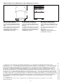
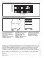
A1 (L+) A2 (L-) Y40
S33
Y39
S34 S14 S13 S11 S12 S31 S32
13
23
37
47
K3
CH2
_
~
+
K1
Start
Unit
CH1
K4
_ _
K2
S22
S21
14
24
38
48
Fig. 1: Innenschaltbild/Internal Wiring Diagram/Schéma de principe
Betriebsarten
Operating Modes
Modes de fonctionnement
• Einkanaliger Betrieb: Eingangsbeschaltung
nach VDE 0113 Teil 1 und EN 60204-1,
keine Redundanz im Eingangskreis,
Erdschlüsse im Tasterkreis werden
erkannt.
• Zweikanaliger Betrieb: Redundanter Eingangskreis, Erdschlüsse im Tasterkreis
und Querschlüsse zwischen den Tasterkontakten werden erkannt.
• Automatischer Start: Gerät ist aktiv, sobald
Eingangskreis geschlossen ist.
• Manueller Start mit Überwachung: Gerät
ist nur aktiv, wenn vor dem Schließen des
Eingangskreises der Startkreis geöffnet
wird und der Startkreis nach dem Schließen des Eingangskreises und nach Ablauf
der Wartezeit (s. techn. Daten) geschlos-
• Single-channel operation: Input wiring
according to VDE 0113 part 1 and
EN 60204-1, no redundancy in the input
circuit, earth faults are detected in the
emergency stop circuit.
• Two-channel operation: Redundancy in
the input circuit, earth faults in the
Emergency Stop circuit and shorts across
the emergency stop push button are also
detected.
• Automatic reset: Unit is active as soon as
the input circuit is closed.
• Manual reset with monitoring: Unit will only
be active if the reset circuit is opened
before the input circuit closes, and the
reset circuit is closed after the input circuit
has closed and the waiting time has
• Commande par 1 canal : conforme aux
prescriptions de la EN 60 204/1, pas de
redondance dans le circuit d’entrée, la
mise à la terre du circuit d’entrée est
détectée
• Commande par 2 canaux: circuit d’entrée
redondant, la mise à la terre et les courtscircuits entre les contacts sont détectés.
• Réarmement automatique : le relais est
activé dès la fermeture des canaux
d’entrée.
• Réarmement manuel auto-contrôlé:
L'appareil est uniquement actif lorsque le
circuit de réarmement est ouvert avant
fermeture des circuits d'entrées et que le
circuit de réarmement est fermé après
fermeture des circuits d'entrées et
-2-
sen wird. Dadurch ist eine automatische
Aktivierung und Überbrückung des
Starttasters ausgeschlossen.
• Kontaktvervielfachung und -verstärkung
durch Anschluss von externen Schützen
Montage
Das Sicherheitsschaltgerät muß in einen
Schaltschrank mit einer Schutzart von mind.
IP 54 eingebaut werden. Zur Befestigung auf
einer Normschiene dient ein Rastelement auf
der Rückseite des Geräts.
Sichern Sie das Gerät bei Montage auf einer
senkrechten Tragschiene (35 mm) durch ein
Halteelement wie z. B. Endhalter oder
Endwinkel.
elapsed (see technical data). This
eliminates the possibility of the reset
button being overridden, triggering
automatic activation.
• Increase in the number of available
contacts by connection of external
contactors/relays.
Installation
The safety relay must be panel mounted
(min. IP 54). There is a notch on the rear of
the unit for DIN-Rail attachment.
If the unit is installed on a vertical mounting
rail (35 mm), ensure it is secured using a
fixing bracket such as end bracket.
Imax =
Rlmax
Rl / km
Rlmax = max. Gesamtleitungswiderstand
(Eingangskreis)
Rl /km = Leitungswiderstand/km
• Da die Funktion Querschlußerkennung
nicht einfehlersicher ist, wird sie von Pilz
während der Endkontrolle geprüft. Eine
Überprüfung nach der Installation des
Geräts ist wie folgt möglich:
1. Gerät betriebsbereit (Ausgangskontakte
geschlossen)
2. Die Testklemmen S22-S32 zur Querschlußprüfung kurzschließen.
3. Die Sicherung im Gerät muß auslösen
und die Ausgangskontakte öffnen. Leitungslängen in der Größenordnung der
Maximallänge können das Auslösen der
Sicherung um bis zu 2 Minuten verzögern.
4. Sicherung wieder zurücksetzen: den
Kurzschluß entfernen und die Versorgungsspannung für ca. 1 Minute abschalten.
• Leitungsmaterial aus Kupferdraht mit einer
Temperaturbeständigkeit von 60/75 °C
verwenden.
• Angaben im Kapitel „Technische Daten“
unbedingt einhalten.
Ablauf:
• Versorgungsspannung an A1 und A2
anlegen.
• Betriebserdungsklemme mit Schutzleitersystem verbinden (Erdschlußerkennung).
• Startkreis:
- Automatischer Start: S13-S14 brücken.
- Manueller Start mit Überwachung: Taster
an S33-S34 anschließen (S13-S14 offen)
• Eingangskreis:
- Einkanalig: S21-S22 und S31-S32
brücken. Öffnerkontakt von Auslöseelement an S11 und S12 anschließen.
- Zweikanalig: S11-S12 brücken.
Öffnerkontakt von Auslöseelement an
S21-S22 und S31-S32 anschließen.
• Reset Verzögerungszeit
Taster oder Brücke an Y39-Y40 anschließen
Montage
Le relais doit être monté en armoire ayant un
indice de protection mini IP 54. Sa face
arrière permet un montage sur rail DIN.
Immobilisez l'appareil monté sur un rail DIN
vertical (35 mm) à l'aide d'un élément de
maintien comme par ex. un support ou une
équerre terminale.
Inbetriebnahme
Beachten Sie bei der Inbetriebnahme:
• Auslieferungszustand: Brücke zwischen
S11-S12 (Eingangskreis zweikanalig) und
Y39-Y40.
• Vor die Ausgangskontakte eine
Sicherung (s. technische Daten)
schalten, um das Verschweißen der
Kontakte zu verhindern.
• Berechnung der max. Leitungslänge Imax
(Eingangskreis):
écoulement du temps d'attente (voir les
charactéristiques techniques). Cette
mesure permet d'éviter toute activation
automatique et toute inhibition du poussoir
de réarmement.
• Augmentation du nombre de contacts ou
du pouvoir de coupure par l’utilisation de
contacteurs externes.
Operation
Please note for operation:
• Unit delivered with a bridge between S11S12 (2-channel input circuit) and Y39-Y40.
• To prevent contact welding, a fuse
should be connected before the output
contacts (see technical details).
• Calculate the max. Cable runs Imax (Input
circuit)
Imax =
Rlmax
Rl / km
Rlmax = Max. Total cable resistance (Input
circuit)
Rl /km = Cable resistance/km
• As the function for detecting shorts across
the inputs is not failsafe, it is tested by Pilz
during the final control check. However, a
test is possible after installing the unit and
it can be carried out as follows:
1. Unit ready for operation (output contacts
closed)
2. Short circuit the test (connection)
terminals S22-S32 for detecting shorts
across the inputs.
3. The unit‘s fuse must be triggered and
the output contacts must open. Cable
lengths in the scale of the maximum length
can delay the fuse triggering for up to 2
minutes.
4. Reset the fuse: remove the short circuit
and switch off the operating voltage for
approx. 1 minute.
• Use copper wiring that will withstand
60/75 °C
• Important details in the section "Technical
Data“ should be noted and adhered to.
To operate:
• Operating voltage:
Connect the operating voltage on the
terminals A1 and A2
• Connect the operating earth terminal
with the ground earth (Earth fault
monitoring).
• Reset circuit:
- Automatic reset: Bridge S13-S14
- Manual reset with monitoring: Connect
button to S33-S34 (S13-S14 open).
• Input circuit:
- Single-channel: Bridge S21-S22 and
S31-S32. Connect N/C contact from
safety switch (e.g. Emergency-Stop) to
S12 and S11.
- Two-channel: Bridge S11-S12. Connect
N/C contact from safety switch (e.g.
Emergency-Stop) to S21-S22 and S31S32.
• Reset delay-on-de-energisation
Connect a button to Y39-Y40 or link Y39Y40
-3-
Mise en oeuvre
Remarques préliminaires :
• Pontages présents à la livraison: S11-S12
(commande par 2 canaux) et Y39-Y40.
• Raccordez un fusible (voir les
caractéristiques techniques) avant les
contacts de sortie afin d’éliminer tout
risque de fusion.
• Calcular les longueurs de câblage max
Imax (Circuits d’entrée):
Imax =
Rlmax
Rl / km
Rlmax = résistivité de câblage totale max.
(Circuits d’entrée)
Rl /km = résistivité de câblage/km
• Utiliser uniquement des fils de cablâge en
cuivre 60/75 °C.
• La fonction de détection de court-circuit est
testé par Pilz lors du contrôle final. Un test
sur site est possible de la façon suivante :
1. Appareil en fonction (contacts de sortie
fermés)
2. Court-circuiter les bornes de
raccordement nécessaires au test S22-S32
3. Le fusible interne du relais doit
déclencher et les contacts de sortie
doivent s‘ouvrir. Le temps de réponse du
fuisible peut aller jusqu‘à 2 min. si les
longueurs de câblage sont proches des
valeurs maximales.
4. Réarmement du fusible : enlever le
court-circuit et couper l‘alimentation du
relais pendant au moins 1 min.
• Respecter les données indiquées dans le
chap. „Caractéristiques techniques“.
Mise en oeuvre :
• Tension d’alimentation:
amener la tension d’alimentation sur A1 et
A2
• Relier la borne de terre (Contrôleur
d’isolement).
• Circuit de réarmement:
- réarmement automatique: pontage des
bornes S13-S14
- réarmement manuel auto-côntrolé:
câblage d'un poussoir sur S33-S34
(S13-S14 ouvert).
• Circuits d’entrée:
- Commande par 1 canal : câblage du
contact à ouverture entre S11-S12,
pontage entre S21-S22 et S31-S32
- Commande par 2 canaux: câblage des
contacts à ouverture entre S21-S22 et
S31-S32, pontage entre S11-S12
• Reset de la temporisation
Poussoir ou pont sur les bornes Y39-Y40
• Rückführkreis:
Externe Schütze in Reihe zu Startkreis
S13-S14 bzw. S33-S34 anschließen.
Die Sicherheitskontakte sind aktiviert (geschlossen). Die Statusanzeige für "CH.1",
"CH. 2", "CH.1(t)" und "CH.2(t)" leuchten.
Das Gerät ist betriebsbereit.
Wird der Eingangskreis geöffnet, öffnen die
Sicherheitskontakte 13-14/23-24 und die
Statusanzeigen "CH.1" und "CH.2" erlöschen. Nach Ablauf der Verzögerungszeit
öffnen die Sicherheitskontakte 37-38/47-48
und die Statusanzeigen "CH.1(t)" und
"CH.2(t)" erlöschen.
Wieder aktivieren
• Eingangskreis schließen.
• Bei manuellem Start mit Überwachung
Taster zwischen S33 und S34 betätigen.
Die Statusanzeigen leuchten wieder, die
Sicherheitskontakte sind geschlossen.
• Feedback control loop:
Connect external relays/contactors in
series to reset circuit S13-S14 or S33-S34
The safety contacts are activated (closed).
The status indicators "CH.1","CH.2", "CH.1(t)
and "CH.2(t)" are illuminated. The unit is
ready for operation. If the input circuit is
opened, the safety contacts 13-14/23-24
open and the status indicators "CH.1" and
"CH.2" extinguish. After the delay-on-deenergisation period the saftey contacts 3738/47-48 open and the status indicators
"CH.1(t)2 and "CH.2(t)" extinguish.
Reactivation
• Close the input circuit.
• For manual reset with monitoring, press
the button and release between S33-S34.
The status indicators light up again, the
safety contacts are closed.
• Boucle de retour:
câbler les contacts des contacteurs
externes en série dans le circuit de
réarmement S13-S14 ou S33-S34
Les contacts de sécurité se ferment. Les
LEDs "CH.1", "CH.2", "CH.1(t)" et "CH.2(t)"
sont allumées. L’appareil est prêt à
fonctionner.
Si le circuit d’entrée est ouvert, les contacts
de sécurité 13-14/23-24 retombent et les
LEDs "CH.1" et "CH.2" s'éteignent. À la fin
de la temporisation, les contacts de sécurité
37-38/47-48 retombent et les LEDs "CH.1(t)"
et "CH.2(t)" s’éteignent.
Remise en route :
• fermer le circuit d’entrée
• en cas de surveillance du circuit de
réarmement, appuyer le poussoir de
validation S33-S34.
Les affichages d'état s'allument à nouveau.
Les contacts de sécurité sont fermées.
Anwendung
Application
Utilisation
In Fig. 2 ... Fig. 10 sind Anschlussbeispiele
für NOT-AUS-Beschaltung mit automatischem und überwachtem Start, Schutztüransteuerungen sowie Kontaktvervielfachung
durch externe Schütze.
Bitte beachten Sie:
• Fig. 2 und 7: keine Verbindung S33-S34
Beachten Sie: Das Gerät startet bei
Spannungsausfall und -wiederkehr
automatisch. Verhindern Sie einen
unerwarteten Wiederanlauf durch externe
Schaltungsmaßnahmen.
• Fig. 3, 4 und 5, 6:
keine Verbindung S13-S14
• Fig. 7: Automatischer Start bei Schutztürsteuerung: Das Gerät ist bei geöffneter
Schutztür über den Startkreis S13-S14
startbereit. Nach Schließen der Eingangskreise S11-S12, S21-S22 und S31-S32
werden die Sicherheitskontakte geschlossen.
In Fig. 2 ... Fig. 10 are connection examples
for Emergency Stop wiring with automatic
and monitored reset. Safety gate controls as
well as contact expansion via external
contactors.
• Fig. 2 and 7: S33-S34 not connected
Please note: The device starts
automatically after loss of power. You
should prevent an unintended start-up by
using external circuitry measures.
• Fig 3, 4 and 5, 6: S13-S14 not connected
• Fig. 6: Automatic reset with safety gate
control: with the safety gate open the unit
is ready for operation via reset circuit S13S14. After closing the safety input circuit
S11-S12, S21-S22 and S31-S32 the
safety contacts will close.
Les figures 2 à 10 représentent les différents
câblages possibles du PNOZ XV2.1 à savoir:
poussoir AU avec réarmement automatique
ou auto-côntrolé, interrupteurs de position et
augmentation du nombre des contacts de
sécurité par contacteurs externes.
• Fig. 2 et 7: pas de câblage sur S33-S34
Dans le cas , l’appareil se réarme
automatiquement après une coupure et
une remise sous tension. Evitez tout risque
de redémarrage par un câblage externe
approprié.
• Fig. 3, 4 et 5, 6:
pas de câblage sur S13-S14
• Fig. 7: Réarmement automatique en cas
de surveillance protecteur: lorsque le
protecteur est ouvert, le circuit S13-S14 se
ferme et le relais est prêt à fonctionner.
Dès la fermeture des canaux d'entrée S11S12, S21-S22 et S31-S32, les contacts de
sortie du relais se ferment.
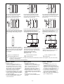
S11 S31 S21 S33 Y39
S11 S31 S21 S13 Y39
S1
S1
S12 S32 S22 S14 Y40
Fig. 2: Eingangskreis einkanalig, automat.
Start/Single-channel input circuit, automatic
reset/Commande par 1 canal, validation
automatique
S21 S31 S11
S1
S3
S12 S32 S22 S34 Y40
Fig. 3: Eingangskreis einkanalig, überwachter Start/Single-channel input circuit,
monitored reset/Commande par 1 canal,
surveillance du poussoir de validation
-4-
S33 Y39
S3
S22 S32 S12
S34 Y40
Fig. 4: Eingangskreis zweikanalig, überwachter Start/Two-channel input circuit, monitored
reset/Commande par 2 canaux, surveillance
du poussoir de validation
S11 S21 S31 S33 Y39
S11
S21
S33 Y39
S21
S1
S1
S1
S22
S31
S3
S22
S31
S3
S2
S12 S22 S32
S34 Y40
Fig. 5: Schutztürsteuerung einkanalig,
überwachter Start/Single-channel safety gate
control, monitored reset/Surveillance de
protecteur, commande par 1 canal,
surveillance du poussoir de validation
S32
S2
S12
S34 Y40
S32
Fig. 6: Schutztürsteuerung zweinkanalig,
überwachter Start/Two-channel safety gate
control, monitored reset/Surveillance de
protecteur, commande par 2 canaux,
surveillance du poussoir de validation
Y39
K5
K7
K7
K8
K8
S13
S14
K5
Y40
13
37
14
38
K6
K7
betätigtes Element/Switch
activated/élément actionné
S33
K5
K6
S3
S34
K5
K8
K6
13
37
14
38
K7
K8
1L2
1L2
Fig. 8: Öffnerkontakt für Reset der
Verzögerungszeit/N/C contact for reseting
the Delay-on De-energisation/Contact à
ouverture pour mise à 0 de la temporisation
S12 Y40
S14
Fig. 7: Schutztürsteuerung zweikanalig,
automatischer Start/Two channel safety gate
control, automatic reset/Surveillance de
protecteur, commande par 2 canaux,
validation automatique
1L1
1L1
K6
S11 Y39
S13
Fig. 9: Anschlussbeispiel für externe
Schütze, einkanalig, automatischer Start/
Connection example for external contactors/
relays, single-channel, automatic reset/
Branchement contacteurs externes,
commande par 1 canal, validation
automatique
Tür nicht geschlossen/Gate open/
porte ouverte
Fig. 10: wie Fig. 9 mit überwachtem Start/
connection for contactors/relays and
monitored reset/comme Fig. 8 avec
surveillance du poussoir de validation
Tür geschlossen/Gate closed/
porte fermée
S1/S2: NOT-AUS- bzw. Schutztürschalter/Emergency Stop Button, Safety Gate Limit Switch/Poussoir AU, détecteurs de position
S3:
Starttaster/Reset button/Poussoir de réarmement
Fehler - Störungen
Faults
Erreurs - Défaillances
• Erdschluss
Eine elektronische Sicherung bewirkt das
Öffnen der Ausgangskontakte. Nach
Wegfall der Störungsursache und
Abschalten der Versorgungsspannung für
ca. 1 min ist das Gerät wieder betriebsbereit.
• Fehlfunktionen der Kontakte: Bei verschweißten Kontakten ist nach Öffnen des
Eingangskreises keine neue Aktivierung
möglich.
• LED "Power" leuchtet nicht: Kurzschluss
oder Versorgungsspannung fehlt.
• Earth fault
An electronic fuse causes the output
contacts to open. Once the cause of the
fault has been removed and operating
voltage is switched off, the unit will be
ready for operation after approximately 1
minute.
• Contact failure: In the case of welded
contacts, no further activation is possible
following an opening of the input circuit.
• LED "Power" is not illuminated if shortcircuit or the supply voltage is lost.
• Défaut de masse
Un fusible électronique entraîne
l’ouverture des contacts de sortie. Une fois
la cause du défaut éliminée et la tension
d’alimentation coupée, l’appareil est à
nouveau prêt à fonctionner après environ 1
minute.
• Défaut de fonctionnement des contacts de
sortie: en cas de soudage d’un contact lors
de l’ouverture du circuit d’entrée, un
nouvel réarmement est impossible.
• LED "Power" éteinte: tension
d'alimentation non présente ou courtcircuit interne.
-5-
Technische Daten/Technical Data/Caractéristiques techniques
Versorgungsspannung UB/Operating Voltage/Tension d’alimentation
Spannungstoleranz/Voltage Tolerance/Plage de la tension d’alimentation
Leistungsaufnahme bei UB/Power Consumption/Consommation
Frequenzbereich/Frequency Range/Fréquence
Spannung und Strom an/Voltage, Current at //Tension et courant du
Eingangskreis/Input circuit/circuit d’entrée
Startkreis/reset circuit/circuit de réarmement
Rückführkreis/feedback loop/boucle de retour
Ausgangskontakte/Output Contacts/Contacts de sortie
Unverzögert/Instantaneous/Instantés
24 - 240 V AC/DC
-15 ... +10 %
UB DC: 5,0 W
UB AC: 8,5 VA
50 - 60 Hz
UB = 24 V DC: 35 mA
UB = 24 V DC: 30 mA
UB = 24 V DC: 3,1 mA
2 Sicherheitskontakte/Safety contacts/
Contacts de securitè
2 Sicherheitskontakte/Safety contacts/
Contacts de securitè
Verzögert/Delayed/Temporisés à retombée
Kategorie nach/Category to/Catégorie d'après EN 954-1, EN ISO 13849-1
Unverzögert/Instantaneous/Instantés
Verzögert <30s / Delayed <30s / Temporisés à retombée <30s
Verzögert ≥30s / Delayed ≥30s / Temporisés à retombée ≥30s
Gebrauchskategorie nach/Utilization category to/Catégorie d’utilisation d'après
EN 60947-4-1
AC1: 240 V
DC 1: 24 V
EN 60947-5-1
AC 15: 230 V
DC13 (6 Schaltspiele/Min, 6 cycles/min, 6 manoeuvres/min): 24 V
Kontaktmaterial/Contact material/Matériau contact
Kontaktabsicherung extern nach/External Contact Fuse Protection/Protection des contacts
EN 60947-5-1 (IK = 1 kA)
Schmelzsicherung/Blow-out fuse/Fusibles
Sicherungsautomat/Safety cut-out/Dijoncteur
Max. Gesamleitungswiderstand Rlmax (Eingangskreis) /Max. total cable resistance Rlmax
(input circuit)/Résistivité de câblage totale max. Rlmax (Circuits d’entrée)
einkanalig DC/Single-channel DC/Commande par 1 canal DC
einkanalig AC/Single-channel AC/Commande par 1 canal AC
zweikanalig mit Querschlußerkennung DC/Dual-channel with detection of shorts across
contacts DC/Commande par 2 canaux avec détection des court-circuits DC
zweikanalig mit Querschlußerkennung AC/Dual-channel with detection of shorts across
contacts AC/Commande par 2 canaux avec détection des court-circuits AC
Einschaltverzögerung/Switch-on delay/Temps d’enclenchement UB = 24 V AC/DC
Automatischer Start/Automatic reset/Réarmement automatique
Automatischer Start nach Netz-Ein/Automatic reset after Power-ON/ Réarmement
automatique après mise sous tension
Überwachter Start/Monitored manual reset/Réarmement manuel auto-contrôlé
Rückfallverzögerung /Delay-on De-Energisation /Temps de retombée
bei NOT-AUS/at E-STOP/en cas d'arrêt d'urgence
bei Netzausfall/with power failure/en cas de coupure d'alimentation UB = 24 V AC/DC
bei Netzausfall/with power failure/en cas de coupure d'alimentation UB = 240 V AC/DC
Verzögerungszeit/Delay-on De-Energisation/Temps de retombée tv
einstellbar/adjustable/réglable
fest/fixed/fixe
Wiederholgenauigkeit/Repetition accuracy/Précision de reproductibilité
Zeitgenauigkeit/Time accuracy/Précision du temps
Wiederbereitschaftszeit bei max. Schaltfrequenz 1/s/recovery time at max. switching
frequency 1/s/temps de remise en service en cas de fréquence de commutation max. 1/s
nach NOT-AUS/after E-STOP/après l'arrêt d'urgence
nach Netzausfall/after power failure/après une coupure d'alimentation UB = 240 V AC
Wartezeit bei überwachtem Start/Waiting period on monitored reset/Temps d’attente en
cas d’un démarrage surveillé
Gleichzeitigkeit Kanal 1 und 2/Simultaneity channel 1 and 2/Désynchronisme canal 1 et 2
Min. Startimpulsdauer bei überwachtem Start/Min. start pulse duration with a monitored
reset/Durée minimale de l'impulsion pour un réarmement auto-contrôlé
Überbrückung bei Spannungseinbrüchen/Max. supply interruption before
de-energisation/Tenue aux micro-coupures
EMV/EMC/CEM
Schwingungen nach/Vibration to/Vibrations d'après EN 60068-2-6
Klimabeanspruchung/Climate Suitability/Conditions climatiques
-6-
4
3
1
Imin: 0,01 A, Imax: 8,0 A, Pmax: 2000 VA
Imin: 0,01 A, Imax: 8,0 A, Pmax: 200 W
Imax: 5,0 A
Imax: 7,0 A
AgSnO2+ 0,2 µm Au
10 A flink/quick acting/rapide oder /or/ou
6 A träge/slow acting/normeaux
24 V AC/DC: 6 A Charakteristik /
Characteristic/Caractéristiques B/C
200 Ohm
200 Ohm
20 Ohm
20 Ohm
typ. 400 ms, max. 550 ms
typ. 625 ms, max. 870 ms
typ. 35 ms, max. 60 ms
typ.: 15 ms, max.: 30 ms
typ.: 120 ms, max.: 500 ms
typ.: 900 ms, max.: 2.200 ms
0,1-3 s: 0,1/0,2/0,3/0,4/0,5/0,6/0,7/0,8/1/
1,5/2/3 s
0-30 s: 0/0,5/1/2/4/6/8/10/15/20/25/30 s
0-300 s: 0/5/10/20/40/60/80/100/150/200/
250/300 s
0,5 s
2%
-15% / +15% +50 ms
50 ms + tv
2.250 ms
300 ms
∞
30 ms
20 ms
EN 50081-1, EN 50081-2, EN 60947-5-1,
EN 61000-6-2, EN 61000-6-4
Frequenz/Frequency/Fréquences:10-55 Hz
Amplitude/Amplitude/Amplitude: 0,35 mm
EN 60068-2-78
Luft- und Kriechstrecken nach/Airgap Creepage to/Cheminement et claquage d'après EN 60947-1
Verschmutzungsgrad/Pollution degree/Niveau d'encrassement
Bemessungsisolationsspannung/Rated insulation voltage/Tension assignée d’isolement
Bemessungsstoßspannungsfestigkeit/Rated impulse withstand voltage/Tension assignée
de tenue aux chocs
Betriebstemperatur/Operating Temperature/Température d’utilisation
Lagertemperatur/Storage Temperature/Température de stockage
Schutzart/Protection/Indice de protection
Einbauraum (z. B. Schaltschrank)/Mounting (eg. panel)/Lieu d'implantation (ex. armoire)
Gehäuse/Housing/Boîtier
Klemmenbereich/Terminals/Bornes
Gehäusematerial/Housing material/Matériau du boîtier
Gehäuse/Housing/Boîtier
Front/Front panel/Face avant
Querschnitt des Außenleiters /Cable cross section/ Capacité de raccordement
1 Leiter, flexibel/1 core, flexible/1 conducteur souple
2 Leiter gleichen Querschnitts, flexibel mit Aderendhülse, ohne Kunststoffhülse/
2 core, same cross section flexible with crimp connectors, without insulating sleeve/
2 conducteurs de même diamètre souple avec embout, sans chapeau plastique
ohne Aderendhülse oder mit TWIN-Aderendhülse/without crimp connectors or with TWIN
crimp connectors/souple sans embout ou avec embout TWIN
Anzugsdrehmoment Schrauben (auf Anschlussklemmen)/Torque setting for connection terminal
screws/Couple de serrage (bornier)
Abmessungen H x B x T/Dimensions H x W x D /Dimensions H x P x L
Einbaulage/Fitting Position/Position de travail
Gewicht/Weight/Poids
Es gelten die 2008-07 aktuellen Ausgaben
der Normen.
The version of the standards current at
2008-07 shall apply.
2
250 V
4 kV
-10 - 55 °C
-40 - 85 °C
IP54
IP40
IP20
PPO UL 94 V0
ABS UL 94 V0
0,20 - 4,00 mm2, 24 - 10 AWG
0,20 - 2,50 mm2, 24 - 14 AWG
0,20 - 2,50 mm2, 24 - 14 AWG
0,60 Nm
87 mm x 90 mm x 121 mm
beliebig; any; indifférente
580 g
Se référer à la version des normes en vigeur
au 2008-07.
Konventioneller thermischer Strom bei gleichzeitiger Belastung mehrerer Kontakte/Conventional thermal
current while loading several contacts/Courant thermique conventionnel en cas de charge sur plusieurs
contacts (AC1, DC1)
Anzahl der Kontakte/number of contacts/nombre des contacts
Ith (A) pro Kontakt bei Versorgungsspannung AC/per contact
with operating voltage AC/par contact pour tension d’alimentation AC
Ith (A) pro Kontakt bei Versorgungsspannung DC/per contact
with operating voltage DC/par contact pour tension d’alimentation DC
Um ein Versagen der Geräte zu verhindern,
an allen Ausgangskontakten für eine ausreichende Funkenlöschung sorgen. Bei
kapazitiven Lasten sind eventuell auftretende
Stromspitzen zu beachten. Bei DC-Schützen
Freilaufdioden zur Funkenlöschung einsetzen, um die Lebendauer der Schütze zu
erhöhen.
4
3
2
1
5,0
5,7
7,0
8,0
5,0
5,7
7,0
8,0
To prevent failure of the unit, all output
contacts should be fused adequately. With
capacative loads, possible current peaks are
to be avoided. With DC contactors/relays
use suitable spark suppression to ensure
extended life of the contactors/relays.
Prévoir un dispositif d’extinction d’arc sur les
contacts de sortie pour éviter un éventuel
disfonctionnement du relais.
Tenir compte des pointes d’intensité en cas
de charge capacitive. Equiper les
contacteurs DC de diodes de roue libre .
Lebensdauer der Ausgangsrelais/Service Life of Output relays/Durée de vie des relais de sortie
Nennbetriebstrom (A)
Nominal operating current (A)
Courant coupé (A)
10
AC15: 230 V
DC1: 24 V
DC13: 24 V
AC1: 230 V
1
0.1
10
100
1000
Schaltspielzahl x 103
Cycles x 103
Nombre de manvres x 103
-7-
10000
121 (4.76")
Abmessungen in mm (")/Dimensions in mm (")/Dimensions en mm (")
75 (2.95")
87 (3.42")
EG-Konformitätserklärung:
EC Declaration of Conformity:
Déclaration de conformité CE :
Diese(s) Produkt(e) erfüllen die Anforderungen der Richtlinie 2006/42/EG über Maschinen des europäischen Parlaments und des
Rates.
Die vollständige EG-Konformitätserklärung
finden Sie im Internet unter www.pilz.com
Bevollmächtigter: Norbert Fröhlich,
Pilz GmbH & Co. KG, Felix-Wankel-Str. 2,
73760 Ostfildern, Deutschland
This (these) product(s) comply with the
requirements of Directive 2006/42/EC of the
European Parliament and of the Council on
machinery.
The complete EC Declaration of Conformity
is available on the Internet at www.pilz.com
Authorised representative: Norbert Fröhlich,
Pilz GmbH & Co. KG, Felix-Wankel-Str. 2,
73760 Ostfildern, Germany
Ce(s) produit(s) satisfait (satisfont) aux
exigences de la directive 2006/42/CE relative
aux machines du Parlement Européen et du
Conseil.
Vous trouverez la déclaration de conformité
CE complète sur notre site internet
www.pilz.com
Représentant : Norbert Fröhlich,
Pilz GmbH & Co. KG, Felix-Wankel-Str. 2,
73760 Ostfildern, Allemagne
A Pilz Ges.m.b.H., ✆ 01 7986263-0, Fax: 01 7986264, E-Mail: [email protected] AUS Pilz Australia, ✆ 03 95446300, Fax: 03 95446311, E-Mail:
B L Pilz Belgium, ✆ 09 3217570, Fax: 09 3217571, E-Mail: [email protected] BR Pilz do Brasil, ✆ 11 4337-1241, Fax: 11 4337-1242,
[email protected]
E-Mail: [email protected]
CH Pilz lndustrieelektronik GmbH, ✆ 062 88979-30, Fax: 062 88979-40, E-Mail: [email protected] DK Pilz Skandinavien K/S,
✆ 74436332, Fax: 74436342, E-Mail: [email protected]
E Pilz lndustrieelektronik S.L., ✆ 938497433, Fax: 938497544, E-Mail: [email protected] F Pilz France
Electronic, ✆ 03 88104000, Fax: 03 88108000, E-Mail: [email protected]
FIN Pilz Skandinavien K/S, ✆ 09 27093700, Fax: 09 27093709, E-Mail:
[email protected]
GB Pilz Automation Technology, ✆ 01536 460766, Fax: 01536 460866, E-Mail: [email protected] I Pilz ltalia Srl, ✆ 031 789511,
Fax: 031 789555, E-Mail: [email protected]
IRL Pilz Ireland Industrial Automation, ✆ 021 4346535, Fax: 021 4804994, E-Mail: [email protected] J Pilz Japan Co.,
Ltd., ✆ 045 471-2281, Fax: 045 471-2283, E-Mail: [email protected]
MEX Pilz de Mexico, S. de R.L. de C.V., ✆ 55 5572 1300, Fax: 55 5572 4194, E-Mail:
[email protected]
NL Pilz Nederland, ✆ 0347 320477, Fax: 0347 320485, E-Mail: [email protected] NZ Pilz New Zealand, ✆ 09- 6345-350, Fax: 09-6345352, E-Mail: [email protected]
P Pilz Industrieelektronik S.L., ✆ 229407594, Fax: 229407595, E-Mail: [email protected] PRC Pilz China Representative
Office, ✆ 021 62494658, Fax: 021 62491300, E-Mail: [email protected]
ROK Pilz Korea, ✆ 031 8159541, Fax: 031 8159542, E-Mail: [email protected]
SE Pilz Skandinavien K/S, ✆ 0300 13990, Fax: 0300 30740, E-Mail: [email protected] TR Pilz Elektronik Güvenlik Ürünleri ve Hizmetleri Tic. Ltd. Şti.,
✆ 0224 2360180, Fax: 0224 2360184, E-Mail: [email protected]
USA Pilz Automation Safety L.P., ✆ 734 354-0272, Fax: 734 354-3355, E-Mail:
[email protected]
www www.pilz.com
D Pilz GmbH & Co. KG, Sichere Automation, Felix-Wankel-Straße 2, 73760 Ostfildern, Deutschland, ✆ +49 711 3409-0, Fax: +49 711 3409-133,
E-Mail: [email protected]
-8-
Originalbetriebsanleitung/Original instructions/Notice originale
20 690-04-2010-02 Printed in Germany
90 (3.54")
20 690-04
PNOZ XV2.1
4
4
4
E
Instrucciones de uso
I
Istruzioni per l`uso
NL Gebruiksaanwijzing
Normas de seguridad
Norme di sicurezza
Veiligheidsvoorschriften
• El dispositivo debe ser instalado y puesto en
funcionamiento solo por personas, que tengan experiencia con estas Instrucciones de
uso y con las normativas vigentes de seguridad del trabajo y prevención de accidentes.
Tenga en cuenta las normativas VDE, como
también las normativas locales, especialmente en lo concerniente a medidas de protección.
• Respetar las exigencias de la norma
EN 60068-2-6referente al transporte,
almacenaje y utilización del dispositivo (v.
datos técnicos).
• La apertura de la carcasa o manipulación
indebida en el dispositivo anulan cualquier
tipo de garantía.
• Monte el dispositivo en un armario de
distribución; de lo contrario el polvo y la
humedad pueden conducir a un mal funcionamiento del dispositivo.
• Todos los contactos de salida sometidos
a cargas capacitivas e inductivas deben
estar convenientemente protegidos.
• L’apparecchio deve essere installato e
messo in funzione solo da persone a
conoscenza delle presenti istruzioni per
l’uso e delle norme antinfortunistiche e di
sicurezza del lavoro vigenti. Si devono
inoltre rispettare le norme VDE, nonché
altre norme locali soprattutto per quanto
riguarda gli interventi di protezione.
• Per il trasporto, l’immagazzinamento ed il
funzionamento, rispettare le norme
EN 60068-2-6 (vedere i dati tecnici).
• In caso di apertura della custodia o di
modifiche non autorizzate, non sarà
riconosciuta alcuna garanzia.
• Montare l’apparecchio in un armadio
elettrico, perché la polvere e l’umidità
potrebbero comprometterne il funzionamento.
• In caso di carichi capacitivi ed induttivi,
assicurare un'adeguata protezione per
tutti i contatti di uscita.
• Het apparaat mag uitsluitend worden
geïnstalleerd en in bedrijf genomen door
personen die vertrouwd zijn met deze
gebruiksaanwijzing en met de geldende
voorschriften op het gebied van arbeidsveiligheid en ongevallenpreventie. Neemt
u de van toepassing zijnde Europese
richtlijnen en de plaatselijke voorschriften
in acht, in het bijzonder m.b.t. veiligheidsmaatregelen.
• Bij transport, opslag en in bedrijf zijn de
richtlijnen volgens EN 60068-2-6 in acht
te nemen (zie technische gegevens).
• Het openen van de behuizing of het eigenmachtig veranderen van de schakeling
heeft verlies van de garantie tot gevolg.
• Monteert u het apparaat in een schakelkast. Stof en vochtigheid kunnen anders
de werking nadelig beïnvloeden.
• Zorgt u bij capacitieve of inductieve
belasting van de uitgangscontacten voor
adequate
contactbeschermingsmaatregelen.
Campo de aplicación
Uso previsto
Toegelaten applicaties
El dispositivo sirve para la interrupción
orientada a la seguridad de un circuito de
corriente de seguridad. El dispositivo de
seguridad cumple los requisitos de las
normas EN 60947-5-1, EN 60204-1 y
VDE 0113-1 y puede utilizarse en
aplicaciones con
• pulsadores de parada de emergencia
• puertas protectoras
Il modulo di sicurezza consente I'interruzione
sicura di un circuito di sicurezza. Il modulo di
sicurezza risponde ai requisiti secondo
EN 60947-5-1, EN 60204-1 e VDE 0113-1 e
può essere utilizzato in applicazioni con
• pulsanti di arresto d'emergenza
• ripari mobili
Het veiligheidsrelais dient om een
veiligheidscircuit veilig te onderbreken. Het
veiligheidsrelais voldoet aan de eisen van
EN 60947-5-1, EN 60204-1 en VDE 0113-1
en mag worde gebruikt in toepassingen met
• noodstopknoppen
• hekken
Descripción del dispositivo
Descrizione dell’apparecchio
Apparaatbeschrijving
El dispositivo de parada de emergencia está
alojado en una carcasa P-97. Hay un modelo
para funcionamiento con tensión de corriente
continua de 24 ... 240 V AC/DC.
Características:
• Salidas por relé, instantáneas:
2 contactos de seguridad (NA), de apertura positiva
• Salidas por relé, con retardo a la desconexión: 2 contactos de seguridad (NA),
con guía forzosa, con retardo a la
desconexión regulable o fijo
• Indicadores de estado para tensión de
alimentación, estado de conexión de todos
los relés de salida y estado de circuito de
rearme
• Conexión para pulsador parada de emergencia, interruptor final de seguridad o
interruptor de puerta protectora y para
pulsador de rearme externo
• Conexión redundante de la salida
• Operación mono o bicanal
• Circuito de realimentación para supervisión de contactores externos
El dispositivo cumple los siguientes requisitos de seguridad:
• El dispositivo de seguridad permanece
también activo en los siguientes casos:
Caída de la tensión, Avería de una pieza,
Bobina defectuosa, Rotura de onductor,
Defecto a tierra
Il modulo di arresto di emergenza è situato
in una custodia P-97. E’ disponibile una
versione per il funzionamento con tensioni
continue di 24 ... 240 V AC/DC.
Caratteristiche:
• Uscite relè non ritardate:
2 contatti di sicurezza (NA), a
conduzione forzata
• Uscite relè con ritardo di scatto:
2 contatti di sicurezza (NA), a
conduzione forzata, con ritardo di scatto
regolabile o fisso
• LED di stato per tensione di alimentazione,
stato di commutazione di tutti i relè di uscita
e stato di circuito di start
• Collegamento per pulsante di arresto di
emergenza, fine corsa di sicurezza o
pulsante porta di protezione, nonché per
pulsante start esterno
• Collegamento di uscita ridondante
• Funzionamento monocanale o bicanale
• Retroazione per il controllo dei relè esterni
L’apparecchio elettrico è conforme ai
seguenti requisiti di sicurezza:
• La funzione di sicurezza è garantita
anche in caso di:
Interruzione della tensione, Guasto di un
componente, Difetto di una bobina,
Interruzione di un conduttore,
Dispersione verso terra
Het noodstoprelais is in een P-97-behuizing
ondergebracht en werkt alleen met 24 ...
240 V AC/DC.
Kenmerken:
• Relaisuitgangen, niet vertraagd:
2 veiligheidscontacten (M), mechanisch
gedwongen
• Relaisuitgangen, afvalvertraagd:
2 veiligheidscontacten (M), mechanisch
gedwongen, met instelbare of vaste
afvalvertraging
• Status-LED’s voor voedingsspanning,
schakeltoestand van alle uitgangsrelais
en startcircuit
• Aansluiting voor noodstopknoppen,
veiligheidseindschakelaars of hekschakelaars en een externe startknop
• Redundante uitgangsschakeling
• Een- of tweekanalig bedrijf
• Terugkoppelcircuit voor de bewaking van
externe magneetschakelaars
Het relais voldoet aan de volgende
veiligheidseisen:
• De veiligheidsvoorziening blijft ook in de
volgende gevallen werken:
Uitvallen van de spanning, Uitvallen van
een component, Defect in een spoel,
Kabelbreuk, Aardsluiting
-9-
• Test en cada ciclo de apertura/cierre para
verificar que los relés de salida del dispositivo
de seguridad abren y cierran correctamente.
• Ad ogni ciclo di inserimento
disinserimento viene controllato se i relè
di uscita dell'apparecchio di sicurezza
siaprono e chiudono correttamente.
• Bij elke aan/uit-cyclus wordt getest of de
uitgangsrelais van het veiligheidscircuit
correct openen en sluiten
Características funcionales
Descrizione del funzionamento
Functiebeschrijving
El relé PNOZ XV2.1 sirve para una interrupción por motivos de seguridad, de un circuito
de seguridad. A la puesta bajo tensión se
enciende el LED „Power“. El dispositivo se
activa si el circuito de rearme S13-S14 está
cerrado o un contacto de rearme en S33S34 fue abierto y nuevamente cerrado. Se
enciende el LED „START“.
• Circuito de entrada cerrado (por ej.
parada de emergencia no accionada):
Los relés K1, K2, K3 y K4 pasan a posición
activa y se automantienen. Los indicadores
de estado „CH.1“, „CH.2“ y „CH.1(t)“,
„CH.2(t)“ se encienden. Los contactos de
seguridad 13-14/23-24/37-38/47-48 están
cerrados.
• Circuito de entrada abierto (por ej. parada
de emergencia accionada):
Los relés K1 y K2 pasan a la posición de
reposo. El indicador de estado „CH.1“ y
„CH.2“ se apagan. Los contactos de seguridad 13-14 y 23-24 se abren de forma redundante. Después de transcurrido el tiempo de
retardo re-gulado, los relés K3 y K4 vuelven a
caer. Los contactos de seguridad 37-38 y 4748 se abren y los LED „CH.1(t)“ y „CH.2(t)“ se
apagan.
Antes de que el dispositivo se pueda rearmar
nuevamente, debe haber transcurrido el
tiempo de retardo y todos los contactos de
parada de emergencia y de seguridad deben
estar cerrados nuevamente (per elemplo
circuito de realimentación).
Interrumpir el tiempo de retardo:
Mediante el accionamiento de un pulsador de
reset (Y39-Y40) se interrumpe el tiempo de
retardo ajustado y los contactos de seguridad
37-38 y 47-48 se abren inmediatamente.
L’apparecchio elettrico PNOZ XV2.1 serve
per interrompere in modo sicuro un circuito
elettrico di sicurezza. Dopo l’applicazione
della tensione di alimentazione si accende il
LED “Power”. L’apparecchio è pronto per
l’uso dopo che è stato chiuso il circuito start
S13-S14, o dopo che un contatto di start su
S33-S34 è stato aperto e nuovamente chiuso.
l LED “START” è acceso.
• Con il circuito di entrata chiuso (per es.
pulsante di arresto di emergenza non
azionato), i relè K1, K2, K3 e K4 si
attivano automantenendosi. I LED di stato
di „CH.1“, „CH.2“ e „CH.1(t)“, „CH.2(t)“
sono accesi. I contatti di sicurezza 13-14/
23-24/37-38/47-48 sono chiusi.
• Quando il circuito di entrata viene aperto
(per es. in caso di azionamento del
pulsante di arresto di emergenza), i relè
K1 e K2 tornano nella posizione di riposo.
La visualizzazione stato per „CH.1” e
„CH.2” si spegne. I contatti di sicurezza
13-14 e 23-24 vengono aperti in modo
ridondante. Al termine del ritardo regolato
i relè K3 e K4 si disattivano. I contatti di
sicurezza 37-38 e 47-48 si aprono ed i
LED „CH.1(t)“ e „CH.2(t)“ si spengono.
Prima do poter riavviare l’apparecchio si deve
attendere il tempo di ritardo e tutti i contatti di
arresto di emergenza e di sicurezza devono
essere nuovamente chiusi (per es.
Retroazione).
Interrompere il tempo di ritardo:
Azionando un tasto reset (Y39-Y40) il tempo di
ritardo regolato viene interrotto ed i contatti di sicurezza 37-38 e 47-48 si aprono immediatamente.
Het relais PNOZ XV2.1 dient om een
veiligheidscircuit met zekerheid te
onderbreken. Zodra de bedrijfsspanning is
ingeschakeld, licht de LED „Power“ op. Het
relais is bedrijfsklaar indien het startcircuit
S13-S14 gesloten is of een startcontact op
S33-S34 geopend en weer gesloten werd.
De LED „START“ licht op.
• Ingangscircuit gesloten (b.v. noodstopknop niet bediend):
de relais K1, K2, K3 en K4 worden
bekrachtigd en nemen zichzelf over. De
status-LED’s voor „CH.1“, „CH.2“ en
„CH.1(t)“, „CH.2(t)“ lichten op. De
veiligheidscontacten 13-14/23-24/37-38/
47-48 zijn gesloten.
• Ingangscircuit wordt geopend
(b.v. noodstopknop bediend):
de relais K1 en K2 vallen af. De LED’s
voor „CH.1“ en „CH.2“ gaan uit. De
veiligheidscontacten 13-14 en 23-24
worden redundant geopend. Na afloop
van de ingestelde vertragingstijd vallen de
relais K3 en K4 af. De veiligheidscontacten 37-38 en 47-48 gaan open en
de LED’s „CH.1(t)“ en „CH.2(t)“ gaan uit.
Voor het relais opnieuw gestart kan worden,
moet de vertragingstijd afgelopen en moeten
alle noodstop- en veiligheidscontacten weer
gesloten zijn (b.v. Terugkoppelcircuit).
Vertragingstijd onderbreken:
Door het indrukken van een resetknop
(Y39-Y40) wordt de ingestelde
vertragingstijd onderbroken en worden de
veiligheidscontacten 37-38 en 47-48 direct
geopend.
A1 (L+) A2 (L-) Y40
S33
Y39
S34 S14 S13 S11 S12 S31 S32
13
23
37
47
K3
CH2
_
~
+
Start
Unit
K1
CH1
K4
_ _
K2
S22
S21
14
24
38
48
Fig. 1: Diagrama de conexionado interno/Schema di collegamento interno/Intern schema
Modos de funcionamiento:
• Modo monocanal: Conexión de la entrada
según VDE 0113 y EN 60204, no existe la
redundancia en el circuito de entrada. Los
defectos a tierra son detectados en el
circuito de paro de emergencia.
• Modo bicanal: Se reconoce el circuito de
entrada redundante. Se detectan los defectos a tierra en el circuito del paro de emergencia. Los cortocircuitos a través del paro
de emergencia también son detectados.
• Rearme automático: El dispositivo se activa tan
pronto como se cierra el circuito de entrada.
Modalità operative:
• Funzionamento monocanale: Cablaggio di
entrata secondo VDE 0113 e EN 60204,
senza ridondanza del circuito di entrata; le
dispersioni verso terra vengono rilevate nel
circuito del pulsante di arresto di emergenza.
• Funzionamento bicanale: Circuito di
entrata ridondante; vengono rilevate le
dispersioni verso terra nel circuito del
pulsante, nonché i cortocircuiti tra i
contatti del pulsante stesso.
• Start automatico: l’apparecchio è attivo
non appena il circuito di entrata è chiuso.
- 10 -
Bedrijfsmodi:
• Eenkanalig bedrijf: ingangsschakeling
volgens VDE 0113 en EN 60204, geen
redundantie in het ingangscircuit.
Aardsluitingen in het ingangscircuit
worden gedetecteerd.
• Tweekanalig bedrijf: redundant ingangscircuit, aardsluitingen in het ingangscircuit
en onderlinge sluitingen tussen de
knopcontacten worden gedetecteerd.
• Automatische start: apparaat is actief
zodra het ingangscircuit gesloten is.
• Rearme manual con supervisión: El
dispositivo se activa solamente si el
circuito de rearme se abre antes de
cerrarse el circuito de entrada y se cierra
después de cerrarse el circuito de entrada
y de transcurrir el tiempo de espera (ver
datos técnicos). De esta forma se excluye
una activación automática y el puenteado
del pulsador de rearme.
• Ampliación y reforzamiento de los
contactos mediante conexión de
ontactores externos.
• Start manuale controllato: il dispositivo è
attivo solo quando, prima della chiusura
del circuito di ingresso, il circuito di start
viene aperto, e chiuso solo dopo la
chiusura del circuito di entrata e al
termine di un tempo di pausa (v. dati
tecnici). In tal modo si esclude
un'attivazione automatica e un'esclusione
del pulsante di start.
• Moltiplicazione ed amplificazione dei contatti
mediante il collegamento di relè esterni.
• Handmatige start met bewaking: apparaat
is alleen actief, als vóór het sluiten van
het ingangscircuit het startcircuit geopend
wordt en na het sluiten van het
ingangscircuit en na afloop van de
wachttijd (zie technische gegevens) het
startcircuit gesloten wordt. Daardoor is
automatische activering door
overbrugging van de startknop
uitgesloten.
• Contactvermeerdering en -versterking
door aansluiting van externe
magneetschakelaars.
Montaje
Montaggio
Montage
El dispositivo de seguridad debe montarse
en un armario e distribución con una
protección mín. de IP 54. Para fijación sobre
una guía DIN dispone de un elemento de
enclavamiento en el lado posterior del
dispositivo. Asegu-re el interface en el
montaje sobre una guía de sujeción (35
mm) vertical mediante un elemento de
fijación como por ej. con un tope terminal o
un ángulo de cierre.
L’apparecchio elettrico di sicurezza deve
es-sere montato in un armadio elettrico con
un tipo di protezione di min. IP 54. Per il
fissag-gio su guida DIN è previsto un
elemento di incastro sul lato posteriore
dell’apparecchio.
Per il montaggio del dispositivo su una guida
DIN (35 mm) usando un elemento di blocco,
per es. un supporto terminale.
Het veiligheidsrelais dient gemonteerd te
worden in een schakelkast die minimaal
voldoet aan beschermingsgraad IP 54.
Bevestiging op een DIN-rail is mogelijk via
de daarvoor bestemde relaisvoet. Bij montage op een verticale draagrail (35 mm) moet
het apparaat worden vastgezet met een
eindsteun.
Puesta en funcionamiento
Messa in funzione
Ingebruikname
En la puesta en funcionamiento tenga en
cuenta lo siguiente:
• Configuración de origen: Puente entre S11S12 (circuito de entrada bicanal) e Y39Y40.
• Protección de los contactos de salida
por fusibles (v. datos técnicos) para
evitar la soldadura de los mismos.
• Máx. longitudes de cable Imax (Circuito de
entrada)
Per la messa in funzione rispettare quanto
segue:
• Stato alla consegna: Ponticello tra
S11-S12 (circuito di entrata bicanale) e
tra Y39 e Y40.
• A monte dei contatti di uscita si deve
collegare un fusibile (vedere i dati
tecnici) per impedire la saldatura tra i
contatti stessi.
• Lunghezze max dei cavi Imax (circuito di
entrata):
Bij ingebruikname in acht nemen:
• Toestand bij levering: Brug tussen
S11-S12 (tweekanalig ingangscircuit)
en Y39-Y40.
• Voor de uitgangscontacten een
zekering (zie technische gegevens)
schakelen om verkleven van de
contacten te voorkomen.
• Max. kabellengte Imax (ingangscircuit):
Imax =
Rlmax
Rl / km
Rlmax = Resistencia de cable maxima total
(Circuito de entrada)
Rl /km = Resistencia de cable / km
• Ya que la función detección de
cortocircui-tos no es segura al primer
fallo, es proba-da por Pilz en el control
final. Una verifi-cación después de la
instalación del dis-positivo es posible de
la siguiente forma:
1. El dispositivo está preparado para funcionar (contactos de salida cerrados)
2. Poner de cortocircuito los bornes de
prueba S22/S32 para la prueba de cortocircuitos.
3. El fusible en el dispositivo se debe
activar y abrirse los contactos de salida.
Los cables de máxima longitud pueden
retardar la activación del fusible hasta
2 minutos.
4. Reponer el fusible: retirar el cortocircuito y desconectar la tensión de
alimentación por aprox. 1 minuto.
• Emplear solo conductores de cobre con
resistencia a temperatura de 60/75 °C.
• Respetar las indicaciones del capítulo
“Datos Técnicos”.
Procedimiento:
• Aplicar la tensión de alimentación en los
bornes A1 y A2.
• Conectar el borne de tierra funcional
con el sistema de puesta a tierra
(Supervisión del contacto a tierra).
• Circuito de rearme:
- Rearme automático: puentear los
bornes S13-S14
- Rearme manual con vigilancia: Cablear
un pulsador entre S33-S34 (S13-S14
abiertos)
Imax =
Rlmax
Rl / km
Rlmax = Resistenza max dei cavi totale
(circuito di entrata)
Rl /km = Resistenza dei cavi / km
• Poiché la funzione di rilevamento cortocircuito non è protetta dagli errori, essa
viene controllata dalla Pilz durante il collaudo finale. Il controllo dell’apparecchio
dopo l’installazione può essere eseguito
nel modo seguente:
1. Apparecchio pronto per l’uso (contatti
di uscita chiusi)
2. Cortocircuitare i morsetti di test
S22/S32 per il controllo dei cortocircuiti.
3. Il fusibile nell’apparecchio deve scattare ed i contatti di uscita si devono aprire.
I cavi di massima lunghezza possono
ritar-dare lo scatto del fusibile fino a 2
minuti.
4. Ripristinare il fusibile: eliminare il cortocircuito e disinserire per ca. 1 minuto la
tensione di alimentazione.
• Usare cavi di rame con una resistenza
termica di 60/75 °C.
• Rispettare assolutamente le indicazioni
riportate nel capitolo “Dati tecnici”.
Procedura:
• Applicare la tensione di alimentazione ai
morsetti A1 e A2.
• Collegare il morsetto della terra
elettrica con il sistema dei conduttori
di protezione (Controllo dei guasti a
terra).
• Circuito di start:
- Start automatico: ponticellare S13-S14.
- Start manuale controllato: collegare il
pulsante a S33-S34 (S13-S14 aperto)
- 11 -
Imax =
Rlmax
Rl / km
Rlmax = Max. Totale kabelweerstand
(ingangscircuit)
Rl /km = kabelweerstand / km
• Omdat de functie detectie van onderlinge
sluiting niet enkelfoutveilig is, wordt deze
door Pilz tijdens de eindcontrole getest.
Een controle na de installatie van het apparaat is als volgt mogelijk:
1. Apparaat bedrijfsklaar (uitgangscontacten gesloten)
2. De testklemmen S22/S32 kortsluiten
om de detectie van onderlinge sluiting te
testen.
3. De zekering in het apparaat moet geactiveerd worden en de uitgangscontacten moeten open gaan. Kabellengten van
ongeveer de maximale lengte kunnen het
activeren van de zekering met max. 2
minuten vertragen.
4. Zekering resetten: de kortsluiting ongedaan maken en de voedingsspanning
voor ca. 1 minuut uitschakelen.
• Kabelmateriaal uit koperdraad met een
temperatuurbestendigheid van 60/75 °C
gebruiken.
• Aanwijzingen in het hoofdstuk „Technische gegevens“ beslist opvolgen.
Gebruik:
• Voedingsspanningop de klemmen A1 en
A2 aansluiten.
• Aardklem met beschermingsaarde
verbinden (Aardsluitingsbewaking).
• Startcircuit:
- Automatische start: S13-S14 verbinden.
- Handmatige start met bewaking: knop
op S33-S34 aansluiten (S13-S14 open)
• Circuito de entrada:
- Monocanal: Puentear S21-S22 y S31S32. Conectar el contacto
normalmente cerrado del interruptor de
seguridad a S11-S12.
- Bicanal: puentear S11-S12 y conectar
los contactos normalmente cerrados
del interruptor de seguridad a S21-S22
y a S31-S32.
• Conectar pulsador de reseteo del tiempo
de retardo
o puente en Y39-Y40
• Circuito de realimentación:
Conectar contactores externos en serie
al circuito de rearme S13-S14 o S33-S34.
Los contactos de seguridad están activados
(cerrados). Los indicadores de estado „CH.1“,
„CH. 2“, „CH.1(t)“ y „CH.2(t)“ están encendidos.
El dispositivo está preparado para funcionar.
Al abrir el circuito de entrada, se abren los contactos de seguridad 13-14/23 y los indicadores
de estado „CH.1“ y „CH.2“ se apagan. Transcurrido el tiempo de retardo, los contactos de
se-guridad 37-38/47-48 se abren y los
indicadores de estado „CH.1(t)“ y „CH.2(t)“ se
apagan.
Reactivación
• Cerrar el circuito de entrada.
• En caso de rearme manual con supervisión, confirmar con el pulsador de rearme
entre S33 y S34.
Los indicadores de estado vuelven a
iluminarse y los contactos de seguridad
están cerrados.
• Circuito di entrata
- Monocanale: ponticellare S21-S22 e
S31-S32. Collegare il contatto di riposo
dell’elemento di scatto a S11 e S12.
- Bicanale: ponticellare S11-S12.
Collegare il contatto di apertura dell’elemento di scatto a S21-S22 e S31-S32.
• Ripristino tempo di ritardo Collegare il
tasto
o il ponticello a Y39-Y40.
• Retroazione: Collegare in serie i contatti
NC dei relè esterni al circuito di start S13S14 o S33-S34.
I contatti di sicurezza sono attivati (chiusi). I
LED “CH.1”, “CH.2", „CH.1(t)“ e „CH.2(t)“
sono accesi. L’apparecchio è pronto per il
funzionamento.
Se viene aperto il circuito di entrata i contatti
di sicurezza 13-14/23-24 si aprono e i LED
“CH1” e “CH2” si spengono. Al termine del
tempo di ritardo i contatti di sicurezza 37-38/
47-48 si aprono e gli indicatori di stato
„CH.1(t)“ e „CH.2(t)“ si spengono.
Riattivazione
• Chiudere il circuito di entrata.
• In caso di start manuale controllato,
azionare il pulsante tra S33 e S34.
Gli indicatori di stato si riaccendono, i
contatti di sicurezza sono chiusi.
• Ingangscircuit:
- Eenkanalig: S21-S22 en S31-S32
verbinden. Verbreekcontact van
bedieningsorgaan op S11 en S12
aansluiten.
- Tweekanalig: S11-S12 verbinden.
Verbreekcontact van bedieningsorgaan
op S21-S22 en S31-S32 aansluiten.
• Reset vertragingstijd
Knop of brug op Y39-Y40 aansluiten.
• Terugkoppelcircuit:
Externe magneetschakelaars in serie met
startcircuit S13-S14 of S33-S34 aansluiten.
De veiligheidscontacten zijn geactiveerd
(gesloten). De status-LED’s voor „CH.1“,
„CH. 2“, „CH.1(t)“ en „CH.2(t)“ lichten op.
Het relais is bedrijfsklaar.
Wordt het ingangscircuit geopend, dan gaan
de veiligheidscontacten 13-14/23-24 open
en de LED’s „CH.1“ en „CH.2“ gaan uit. Na
afloop van de vertragingstijd gaan de
veiligheidscontacten 37-38/47-48 open en
de LED’s „CH.1(t)“ en „CH.2(t)“ doven.
Opnieuw activeren
• Ingangscircuit sluiten.
• Bij handmatige start met bewaking de
knop tussen S33 en S34 indrukken.
De status-LED’s lichten weer op, de
veiligheidscontacten zijn gesloten.
Aplicación
Uso
Toepassing
En las fig. 2... a fig. 10 se presentan ejemplos
de conexionado posibles; paro de emergencia. Los cortocircuitos a través del paro de
emergencia también son detectados.
Por favor tenga en cuenta:
• Fig. 2 y 7: S33-S34 no conectado
Tenga en cuenta: En caso de caida de
tensión y rearranque, el dispositivo se inicia
automáticamente. Evite un arranque
intempestivo mediante un cableado externo
adecuado.
• Fig. 3, 4 y 5, 6: S13-S14 no conectado
• Fig. 7: Rearme automático para el control
de puerta protectora: El dispositivo está
preparado par rearmarse cuando la puerta
protectora está abierta, mediante el circuito
de rearme S13-S14. Después de cerrar los
circuito de entrada S11-S12, S21-S22 y
S31-S32 se cerrarán los contacto
In fig. 2 ... fig. 10 sono riportati degli esempi di
collegamento per il cablaggio di arresto d’emergenza con start automatico e manuale, per il
comando delle porte di sicurezza, nonché per
la moltiplicazione dei contatti mediante relè
esterni.
Nota bene:
• Fig. 2 e 7: nessun collegamento S33-S34
Nota: il dispositivo si avvia
automaticamente dopo la caduta ed il
ritorno dell’alimentazione. Occorre
prevenire un riavvio inatteso usando
circuiti esterni di misura.
• Fig. 3, 4 e 5, 6: nessun colleg. S13-S14
• Fig. 7: Start automatico per comando
porte di sicurezza: Con la porta di
sicurezza aperta, l’apparecchio è pronto
per lo start attraverso il circuito start S13S14. Dopo la chiusura dei circuiti di
entrata S11-S12, S21-S22 e S31-S32 i
contatti di sicurezza vengono chiusi.
In fig. 2 ... 10 worden aansluitvoorbeelden
gegeven van noodstopschakelingen met
automatische en bewaakte start,
hekbewakingen en contactvermeerdering
d.m.v. externe magneetschakelaars.
Let op:
• Fig. 2 en 7: geen verbinding S33-S34
Opgelet: het apparaat start automatisch
bij uitvallen en terugkeren van de
spanning. Vermijd een onverwacht
heraanlopen door maatregelen in de
externe schakeling.
• Fig. 3, 4 en 5, 6: geen verbinding S13S14
• Fig. 7: Automatische start bij hekbewaking: het relais is bij geopende
hekbewaking startklaar via het
startcircuit S13-S14. Na het sluiten van
de ingangscircuits S11-S12, S21-S22 en
S31-S32 worden de veiligheidscontacten
gesloten.
- 12 -
S11 S31 S21 S33 Y39
S11 S31 S21 S13 Y39
S1
S1
S1
S3
S12 S32 S22 S34 Y40
S12 S32 S22 S14 Y40
Fig. 2: Circuito de entrada monocanal,
automát. rearme/Circuito di entrata
monocanale, start automat./Eenkanalig
ingangscircuit, automatische start
S21 S31 S11
S11 S21 S31 S33 Y39
S21
S13
S1
S22
S31
S22
S31
S3
S2
S12 S22 S32
S34 Y40
Fig. 5: Control de puerta protectora
monocanal, rearme supervisado/Comando
porta di sicurezza monocanale, start controllato/Eenkanalige hekbewaking, bewaakte
start
S32
S2
S12
S34 Y40
Fig. 6: Control de puerta protectora bicanal,
rearme supervisado/Comando porta di
sicurezza bicanale, start controllato/
Tweekanalige hekbewaking, bewaakte start
1L1
K6
K5
S32
1L1
K7
Y39
K8
13
S14
37
K5
K6
S3
S34
K7
Fig. 8: Contacto normalmente cerrados
para reseteo del tiempo de retardo/Contatto
di riposo per il ripristino del tempo di ritardo/
Verbreekcontact voor het resetten van de
vertragingstijd
Elemento accionado/Elemento
azionato/Bekrachtigd element
S1/S2:
S3:
37
14
38
K8
K5
Y40
13
38
14
K6
S12 Y40
K8
S33
K5
S14
Fig. 7: Control de puerta protectora bicanal,
rearme automático/Comando porta di sicurezza bicanale, start automatico/
Tweekanalige hekbewaking, automatische
start
K7
S13
S11 Y39
S1
S1
S3
S34 Y40
Fig. 4: Circuito de entrada bicanal, rearme
supervisado/Circuito di entrata bicanale,
start controllato/Tweekanalig ingangscircuit,
bewaakte start
S33 Y39
S11
S21
S3
S22 S32 S12
Fig. 3: Circuito de entrada monocanal,
rearme supervisado/Circuito di entrata
monocanale, start controllato/Eenkanalig
ingangscircuit, bewaakte start
S33 Y39
K6
K7
K8
1L2
Fig. 9: Ejemplo de conexión para
contactores externos, monocanal, rearme
automático/Esempio di collegamento per
relè esterni, monocanale, start automatico/
Aansluitvoorbeeld van externe
magneetschakelaars, eenkanalig,
automatische start
Puerta abierta/Porta aperta/
Hek niet gesloten
1L2
Fig. 10: como la Fig. 9 con rearme supervisado/come fig. 9 con start controllato/
Zoals fig. 9 met bewaakte start
Puerta cerrada/Porta chiusa/
Hek gesloten
Pulsador de paro de emergencia o interruptor de puerta protectora/Pulsante di arresto di emergenza o di porta di sicurezza/
Noodstop- of hekschakelaar
Pulsador de rearme/Pulsante di start/Startknop
Defectos - Averías
Errori - guasti
Fouten - Storingen
• Defecto a tierra
La tensión de alimentación cae y los
contactos de seguridad se abren a través
de un fusible electrónico. Una vez haya
desaparecido la causa del error y se haya
desconectado la tensión de alimentación
durante aprox. 1 minuto, el dispositivo
volverá a estar listo para el servicio.
• Funcionamiento defectuoso de los contactos: En contactos soldados no es posible
reactivar el dispositivo después de abrirse
el circuito de entrada.
• No está encendido el LED “Power”: Falta
la tensión de alimentación o existe un
cortocircuito interno.
• Dispersione verso terra
Un fusibile elettronico interrompe
l’alimentazione ed i contatti di sicurezza si
aprono. Una volta rimossa la causa del
guasto e interrotto la tensione di
alimentazione, il dispositivo sarà pronto al
funzionamento dopo circa un minuto.
• Malfunzionamenti dei contatti: In caso di
contatti saldati tra loro, non è possibile la
riattivazione dopo l’apertura del circuito di
entrata.
• Il LED „Power“ non si accende:
cortocircuito o tensione di alimentazione
interrotta.
• Aardsluiting
De voedingsspanning valt uit en de
veiligheidscontacten worden via een
elektronische zekering geopend. Na het
wegvallen van de storingsoorzaak en het
uitschakelen van de bedrijfsspanning voor
ca. 1 minuut is het apparaat weer
• Contactfout: bij verkleefde contacten is
na het openen van het ingangscircuit
geen nieuwe activering mogelijk.
• LED „Power“ licht niet op: kortsluiting of
geen voedingsspanning.
- 13 -
Datos técnicos/Dati tecnici/Technische gegevens
Tensión de funcionamiento UB/Tensione di alimentazione UB/Voedingsspanning UB
Tolerancia de tensión/Tolleranza di tensione/Spanningstolerantie
Consumo de energía con UB/Potenza assorbita con UB/Opgenomen vermogen bij UB
Rango de frequencia/Gamma di frequenza/Frequentiebereik
Tensiòn y corriente en/Tensione e corrente su/Spanning en stroom op
Circuito de entrada/Circuito di entrata/Ingangscircuit
Circuito de rearme/Circuito di start/startcircuit
Circuito de realimentaciòn/Circuito di retroazione/Terugkoppelcircuit
Contactos de salida/Contatti di uscita/Uitgangscontacten
Sin retardo/Istantanei/Niet vertraagd
Con retardo/Ritardati/Vertraagd
Categoría según/Categoria secondo/Categorie volgens EN 954-1, EN ISO 13849-1
Sin retardo/Istantanei/Niet vertraagd
Con retardo <30s / Ritardati <30s / Vertraagd <30s
Con retardo ≥30s / Ritardati ≥30s / Vertraagd ≥30s
Categóría de uso según/Categoria d' uso secondo/Gebruikscategorie volgens
EN 60947-4-1
AC1: 240 V
DC 1: 24 V
EN 60947-5-1
AC 15: 230 V
DC13 (6 ciclos/Min, 6 cicli di commutazione/min, 6 schakelingen/min): 24 V
Materiál de contactos/materiale di contatto/Contactmateriaal
Protección contactos externos/Protezione esterna dei contatti/Contactafzekering extern
EN 60947-5-1 (IK = 1 kA)
Fusible/Fusibile/Smeltzekering
Fusible automático/Interuttore automatico/Zekeringautomaat
Resistencia de línea total max. Rlmax circuitos de entrada/Mass. resistenza cavo totale Rlmax
circuito di ingresso/Max. weerstand totale kabel Rlmax ingangscircuits
monocanal DC/canale singolo DC/eenkanalig DC
monocanal AC/canale singolo AC/eenkanalig AC
bicanal con detección de cortocircuitos DC/bicanale con riconoscimento di cortocircuito
traversale DC/tweekanalig met detectie van onderlinge sluiting DC
bicanal con detección de cortocircuitos AC/bicanale con riconoscimento di cortocircuito
traversale AC/tweekanalig met detectie van onderlinge sluiting AC
Retardo de la connexión/Ritardo dell' azionamento/Aantrekvertraging; UB = 24 V AC/DC
Rearme automático/Start automatico/Automatische start
Rearme automático tras conexión de red/Start automatico dopo attivazione
dell'alimentazione di rete/Automatische start na netinschakeling
Rearme supervisado/Start controllato/Bewaakte start
Retardo a la desconexión/Ritardo di sgancio/Afvalvertraging
En parada de emergencia/In caso di arresto di emergenza/Bij noodstop
En fallo de la red/In caso di mancanza di tensione/Bij uitvallen spanning UB = 24 V AC/DC
En fallo de la red/In caso di mancanza di tensione/Bij uitvallen spanning UB = 240 V AC/DC
Tiempo de retardo/Tempo di ritardo/Vertragingstijd tv
ajustable/impostabile/instelbaar
fijo/fisso/vast
Precisión de repetitión/Precisione della ripetibilità/Herhalingsnauwkeurigheid
Precisión cronológica/Precisione del tempo/Tijdnauwkeurigheid
Tiempo de recuperación con la frecuencia máxima de 1/s / Tempo di ripristino par frequenza
di commutazione max. 1/s / Resettijd bij max. schakelfrequentie 1/s
Después de una parada de emergencia/dopo un arresto di emergenza/Na noodstop
Después de un fallo de la red /Dopo una mancanza di tensione/Na uitvallen van de
spanning UB = 240 V AC
Tiempo de espera en caso de rearme supervisado/Intervallo di attesa in caso di start
controllato/Wachttijd bej bewaakte start cas d’un démarrage surveillé
Simultaneidad canal 1 y 2/Simultaneità canale 1 e 2/Gelijktijdigheit kanaal 1 en 2
Duración mínima de la senal de arranque con arranque supervisado/Durata minima impulso
di start con start controllato/Min. startpulsduur bij bewaakte start
Immunidad a cortes de tensión/Cavallottamento durante le cadute di tensione/
Overbrugging bij spanningstortingen
CEM/Compatibilità elettromagnetica/EMC
Oscillaciones según/Vibrazioni secondo norma/Trillingen volgens EN 60068-2-6
Condiciones climáticas/Sollecitazione climatica/Klimaacondities
- 14 -
24 - 240 V AC/DC
-15 ... +10 %
UB DC: 5,0 W
UB AC: 8,5 VA
50 - 60 Hz
UB = 24 V DC: 35 mA
UB = 24 V DC: 30 mA
UB = 24 V DC: 3,1 mA
2 Contactos de seguridad/Contatti di
sicurezza/Veiligheidscontacten
2 Contactos de seguridad/Contatti di
sicurezza/Veiligheidscontacten
4
3
1
Imin: 0,01 A, I max: 8,0 A, Pmax: 2000 VA
Imin: 0,01 A, Imax: 8,0 A, Pmax: 200 W
Imax: 5,0 A
Imax: 7,0 A
AgSnO2+ 0,2 µm Au
10 A de acción rápida/rapido/snel ó/o/of
6 A de acción lenta/ritardato/traag
24 V AC/DC: 6 A Característica /
Caratteristica/Karakteristiek B/C
200 Ohm
200 Ohm
20 Ohm
20 Ohm
typ. 400 ms, max. 550 ms
typ. 625 ms, max. 870 ms
typ. 35 ms, max. 60 ms
typ.: 15 ms, max.: 30 ms
typ.: 120 ms, max.: 500 ms
typ.: 900 ms, max.: 2.200 ms
0,1-3 s: 0,1/0,2/0,3/0,4/0,5/0,6/0,7/0,8/1/
1,5/2/3 s
0-30 s: 0/0,5/1/2/4/6/8/10/15/20/25/30 s
0-300 s: 0/5/10/20/40/60/80/100/150/200/
250/300 s
0,5 s
2%
-15% / +15% + 50 ms
50 ms + tv
2.250 ms
300 ms
∞
30 ms
20 ms
EN 50081-1, EN 50081-2, EN 60947-5-1,
EN 61000-6-2, EN 61000-6-4
Frecuencia/Frequ./Frequentie: 10-55 Hz
Amplitud/Ampiezza/Amplitude: 0,35 mm
EN 60068-2-78
Distancias de fuga y dispersión superficial según/Intraferri d'aria e vie di dispersione secondo/
Lucht- en kruipwegen volgens EN 60947-1
Grado de suciedad/Grado di contaminazione/Vervuilingsgraad
2
Tensión de aislamiento de dimensionado/Tensione nominale di isolamento/
Nominale isolatiespanning
250 V
Resistencia tensión transitoria de dimensionado/Tensione di tenuta agli urti/Nominale
stootspanningbestendigheid
4 kV
Temperatura ambiente/Temperatura ambiete/Omgevingstemperatuur
-10 - 55 °C
Temperatura de almacenaje/Temperatura di magazzinaggio/Opslagtemperatuur
-40 - 85 °C
Tipo de protección/Tipi di protezione/Veiligheidsklasse
Lugar de montaje (p.e. armario de distribución)/Spazio di montaggio (p.e. quadro elettrico
ad armadio)/Inbouwruimte (bijv. schakelast)
IP54
Carcassa/Alloggiamento/Kast
IP40
Zona de bornes/Terminali/Aansuitklemmen
IP20
Material de carcassa/materiale della custodia/Behuizingsmateriaal
Carcassa/Alloggiamento/Behuizing
PPO UL 94 V0
Frente/Fronte/Front
ABS UL 94 V0
Seccion del conductor externo/Sezione del cavo esterno /Doorsnede van de aansluitkabels
1 conductor flexible/1 conduttore flessibile/1 draad, flexibel
0,20 - 4,00 mm2, 24 - 10 AWG
2 conductores de misma sección, flexible con terminal: sin revestimiento de plástico /
2 conduttori con lo stesso diametro, flessibile con capocorda senza manicotto di plastica/
2 draaden mad dezelfde doorsnede, flexibel met adereindhuls zonder kunststoffhuls
0,20 - 2,50 mm2, 24 - 14 AWG
lexible sin terminal o con terminal TWIN/flessibile senza capocorda o con capocorda
TWIN/Flexibel zonder adereindhuls of met TWIN-Adereindhuls
0,20 - 2,50 mm2, 24 - 14 AWG
Par de apriete para los bornes de tornillo/Coppia di serraggio per morsetti a vite/
Aanhaalmoment voor schoefklemmen
0,60 Nm
Dimensiones Al x An x Pr / Misure altezza x larghezza x profondità / Afmetingen h x b d
87 mm x 90 mm x 121 mm
Einbaulage/Fitting Position/Position de travail
cualquiera/a scelta/willekeurig
Gewicht/Weight/Poids
580 g
Son válidas las versiones actuales de las
normas 2008-07.
Per le norme citate, sono applicate le versioi
in vigore a 2008-07.
Van toepassing zijn de in 2008-07 actuele
versies van de normen.
Corriente térmica convencional de los contactos de seguridad/Corrente termica convenzionale dei contatti di
sicurezza/Conventionele thermische stroom van de veiligheidscontacten (AC1, DC1)
Número de contactos/Numero dei contatti/Aantal contacten
Ith (A) por contacto en tensión de alimentación AC/
per contatto con corrente AC/per contact bij een AC voedingsspanning
Ith (A) por contacto en tensión de alimentación DC/
per contatto con corrente DC/per contact bij een DC voedingsspanning
Para evitar una falla de los dispositivos, se debe
procurar una suficiente extinción de chispas en
todos los contactos de salida. En cargas
capacitivas se deben tener en cuenta los picos de
corriente. Con contactores de DC, utilizar diodos
de marcha libre para la extinción de chispas, para
aumentar la vida útil de los contactores.
4
3
2
1
5,0
5,7
7,0
8,0
5,0
5,7
7,0
8,0
Per impedire l’avaria dei dispositivi, assicu-rare su
tutti i contatti di uscita un sufficiente spegnimento
della scintilla. Per i carichi ca-pacitivi, rispettare
gli eventuali picchi di cor-rente. Per i relè DC,
utilizzare diodi auto-scillanti per lo spegnimento
della scintilla per aumentare la durata dei relè
stessi.
- 15 -
Om een falen van de relais te verhinderen, moet
aan alle uitgangscontacten voor een adequate
vonkblussing gezorgd worden. Bij capacitieve
belasting dienen eventueel op-tredende
stroompieken vermeden te wor-den. Bij DCmagneetschakelaars vrijloopdioden voor
vonkblussing gebruiken om de levensduur van de
magneetschakelaars te verlengen.
Corriente nominal de servicio (A)
Corrente di esercizio nominale (A)
Nominale bedrijfsstroom (A)
Vida útil del relé de salida/Durata dei relè di uscita/Levensduur van de uitgangsrelais
10
AC15: 230 V
DC1: 24 V
DC13: 24 V
1
0.1
10
AC1: 230 V
100
1000
Número de ciclos x 103
Numero dei cicli di commutazione x 103
Aantal schakelingen x 103
10000
121 (4.76")
Dimensiones en mm (")/Dimensioni in mm (")/Afmetingen in mm (")
75 (2.95")
87 (3.42")
Declaración CE de conformidad:
Dichiarazione di conformità CE:
EG-conformiteitsverklaring:
Estos productos cumplen los requisitos de
la Directiva de Máquinas 2006/42/CE del
Parlamento Europeo y del Consejo.
La declaración CE de conformidad completa
pueden encontrarla en la página web de
Internet www.pilz.com
Apoderado: Norbert Fröhlich,
Pilz GmbH & Co. KG, Felix-Wankel-Str. 2,
73760 Ostfildern, Deutschland
Questo(i) prodotto(i) soddisfa i requisiti della
Direttiva 2006/42/CE del Parlamento e del
Consiglio Europeo sulle macchine.
Il testo integrale della Dichiarazione di
conformità CE è disponibile in Internet
all’indirizzo www.pilz.com
Mandatario: Norbert Fröhlich,
Pilz GmbH & Co. KG, Felix-Wankel-Str. 2,
73760 Ostfildern, Germania
Deze produkten voldoen aan de eisen van
de Europese Machinerichtlijn 2006/42/EG.
De volledige EG-conformiteitsverklaring
vindt u op wwww.pilz.com
Gevolmachtige: Norbert Fröhlich,
Pilz GmbH & Co. KG, Felix-Wankel-Str. 2,
73760 Ostfildern, Duitsland
A Pilz Ges.m.b.H., ✆ 01 7986263-0, Fax: 01 7986264, E-Mail: [email protected] AUS Pilz Australia, ✆ 03 95446300, Fax: 03 95446311, E-Mail:
[email protected]
B L Pilz Belgium, ✆ 09 3217570, Fax: 09 3217571, E-Mail: [email protected] BR Pilz do Brasil, ✆ 11 4337-1241, Fax: 11 4337-1242,
E-Mail: [email protected]
CH Pilz lndustrieelektronik GmbH, ✆ 062 88979-30, Fax: 062 88979-40, E-Mail: [email protected] DK Pilz Skandinavien K/S,
✆ 74436332, Fax: 74436342, E-Mail: [email protected]
E Pilz lndustrieelektronik S.L., ✆ 938497433, Fax: 938497544, E-Mail: [email protected] F Pilz France
Electronic, ✆ 03 88104000, Fax: 03 88108000, E-Mail: [email protected]
FIN Pilz Skandinavien K/S, ✆ 09 27093700, Fax: 09 27093709, E-Mail:
[email protected]
GB Pilz Automation Technology, ✆ 01536 460766, Fax: 01536 460866, E-Mail: [email protected] I Pilz ltalia Srl, ✆ 031 789511,
Fax: 031 789555, E-Mail: [email protected]
IRL Pilz Ireland Industrial Automation, ✆ 021 4346535, Fax: 021 4804994, E-Mail: [email protected] J Pilz Japan Co.,
Ltd., ✆ 045 471-2281, Fax: 045 471-2283, E-Mail: [email protected]
MEX Pilz de Mexico, S. de R.L. de C.V., ✆ 55 5572 1300, Fax: 55 5572 4194, E-Mail:
[email protected]
NL Pilz Nederland, ✆ 0347 320477, Fax: 0347 320485, E-Mail: [email protected] NZ Pilz New Zealand, ✆ 09- 6345-350, Fax: 09-6345352, E-Mail: [email protected]
P Pilz Industrieelektronik S.L., ✆ 229407594, Fax: 229407595, E-Mail: [email protected] PRC Pilz China Representative
Office, ✆ 021 62494658, Fax: 021 62491300, E-Mail: [email protected]
ROK Pilz Korea, ✆ 031 8159541, Fax: 031 8159542, E-Mail: [email protected]
SE Pilz Skandinavien K/S, ✆ 0300 13990, Fax: 0300 30740, E-Mail: [email protected] TR Pilz Elektronik Güvenlik Ürünleri ve Hizmetleri Tic. Ltd. Şti.,
✆ 0224 2360180, Fax: 0224 2360184, E-Mail: [email protected]
USA Pilz Automation Safety L.P., ✆ 734 354-0272, Fax: 734 354-3355, E-Mail:
[email protected]
www www.pilz.com
D Pilz GmbH & Co. KG, Sichere Automation, Felix-Wankel-Straße 2, 73760 Ostfildern, Deutschland, ✆ +49 711 3409-0, Fax: +49 711 3409-133,
E-Mail: [email protected]
- 16 -
Manual de Instrucciones original/Istruzioni originali/Originele bedrijfshandleiding
20 690-04-2010-02 Printed in Germany
90 (3.54")