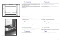
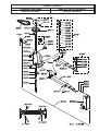
1
I
301
GB
F
D
E
D/08
SOLLEVATORE ELETTROMECCANICO A 2 COLONNE
2-POST ELECTRO-MECHANICAL LIFT
ÉLÉVATEUR ÉLECTROMÉCANIQUE À 2 COLONNES
ELEKTROMECHANISCHE HEBEBÜHNE MIT 2 SÄULEN
ELEVADOR ELECTROMECANICO DE 2 COLUMNAS
Manuale di istruzioni per l’uso e la manutenzione del
Instructions and maintenance manual for
Manuel d’instructions pour l’utilisation et l’entretien du:
Bedienungs- und Wartungsanleitung für
Manual de instrucciones para uso y mantenimiento de los
SOLLEVATORE ELETTROMECCANICO A 2 COLONNE
2-POST ELECTRO-MECHANICAL LIFT
ÉLÉVATEUR ÉLECTROMÉCANIQUE À 2 COLONNES
ELEKTROMECHANISCHE HEBEBÜHNE MIT 2 SÄULEN
ELEVADOR ELECTROMECANICO DE 2 COLUMNAS
Modello - Model - Modèle - Modell - Modelos
301
Matricola N° - Serial N° - N° de série - Matrikelnummer - Matrícula n°
Anno di costruzione - Year of manufacture - Année de fabrication - Baujahr - Año de fabricación
COSTRUTTORE: - MANUFACTURER: - CONSTRUCTEUR: - HERSTELLER: - FABRICANTE:
WERTHER INTERNATIONAL S.p.A.
Via F. BRUNELLESCHI, 12
42100 CADE’ (RE) - ITALY
Telefono ++ / +522 / 9431 (r.a.) - Telefax ++ / +522 / 941997
WEB http://www.wertherint.com - E-mail [email protected]
1a Emissione - 23 Maggio 2006 - 1st Edition - 23 May 2006
1a Édition - 23 Mai 2006 - 1. Ausgabe - 23 Mai 2006 - 1ª Edición – 23 Mayo 2006
CENTRO DI ASSISTENZA AUTORIZZATO:
AUTHORISED SERVICE CENTRE:
SERVICE APRÈS-VENTE AGRÉÉ:
KUNDENDIENSTCENTER
CENTRO DE ASISTENCIA AUTORIZADO:
Rev.1 . . . . . . . . . . . . . . . . . 21/04/2008
1
Contents
Indice
Imballaggio, trasporto e stoccaggio
Pag.4
Packing, transport and storage
Page 4
Introduzione
Pag.6
Introduction
Page 6
Cap.1 Descrizione della macchina Pag.10
2
Chapter 1
Description of
the machine
Page 10
Cap.2 Specifiche tecniche
Pag.14
Chapter 2
Technical specifications Page 14
Cap.3 Sicurezza
Pag.20
Chapter 3
Safety
Page 20
Cap.4 Installazione
Pag.32
Chapter 4
Installation
Page 32
Cap.5 Funzionamento ed uso
Pag.54
Chapter 5
Operating principles
and use
Page 54
Cap.6 Manutenzione
Pag.56
Chapter 6
Maintenance
Page 56
Cap.7 Inconvenienti e rimedi
Pag.62
Chapter 7
Troubleshooting
Page 62
Appendice A Informazioni
Pag.65
Appendix A Special notes
Page 65
Appendice B Parti di ricambio
Pag.65
Appendix B Spare parts
Page 65
Indice
Inhaltsverzeichnis
Table des matières
Emballage, transport et stockage
Page 5
Verpackung, Transport und Lagerung Seite 5
Embalaje, transportey almacenaje
Pág. 5
Introduction
Page 7
Einleitung
Seite 7
Introducción
Pág. 7
Chap.1 Description de l’appareil
Page 10
Kap.1 Maschinenbeschreibung
Seite 10
Cap.1 Descripción de la máquina
Pág. 10
Chap.2 Caractéristiques techniques Page 14
Kap.2 Technische Spezifikationen Seite 14
Cap.2 Datos técnicos
Pág.14
Chap.3 Sécurité
Page 20
Kap.3 Sicherheit
Seite 20
Cap.3 Seguridad
Pág. 20
Chap.4 Installation
Page 32
Kap.4 Aufstellung
Seite 32
Cap.4 Instalación
Pág. 32
Chap.5 Fonctionnement et utilisation Page 54
Kap.5 Betrieb und Gebrauch
Seite 54
Cap.5 Funcionamiento y uso
Pág. 54
Chap.6 Entretien
Page 56
Kap.6 Wartung
Seite 56
Cap.6 Mantenimento
Pág. 56
Chap.7 Pannes et remèdes
Page 62
Kap.7 Störungen und Abhilfen
Seite 62
Cap.7 Inconvenientes y remedios
Pág. 62
Besondere
Informationen
Seite 65
Apéndice A Informaciones
particulares
Pág.65
Ersatzteile
Seite 65
Apéndice B Piezas de recambio
Pág.65
Annexe A
Annexe B
Anhang A
Informations
particulières
Page 65
Pièces détachées
Page 65
Anhang B
3
IMBALLAGGIO, TRASPORTO E
STOCCAGGIO.
Fig.1 - Abb.1
Fig.2 - Abb.2
Fig.3 - Abb.3
4
PACKING, TRANSPORT AND STORAGE
LE OPERAZIONI DI IMBALLAGGIO,
SOLLEVAMENTO, MOVIMENTAZIONE, TRASPORTO
E DISIMBALLO DEVONO ESSERE AFFIDATE
ESCLUSIVAMENTE A PERSONALE CHE SIA
ESPER-TO IN TALI OPERAZIONI E CHE CONOSCA
BENE IL SOLLEVATORE ED IL PRESENTE MANUALE
ALL PACKING, LIFTING, HANDLING, TRANSPORT
AND UNPACKING OPERATIONS ARE TO BE PERFORMED EXCLUSIVELY BY EXPERT PERSONNEL
WITH KNOWLEDGE OF THE LIFT AND THE CONTENTS OF THIS MANUAL
IMBALLAGGIO
Il sollevatore viene spedito smontato nei seguenti pezzi:
Peso
1
Basamento
Kg 100
1
Colonna completa di carrello,vite,
chiocciola, motorizzazione
e quadro elettrico
Kg 160
1
Colonna libera completa di carrello,
vite, chiocciola
Kg 135
2
Bracci lunghi
Kg 54
2
Bracci corti
Kg 44
2
Carter protezione colonna
Kg 4
2
Pedane di copertura basamento
Kg 20
1
Pacco accessorio
Kg 25
contenente:
4 Kit bloccaggio braccio con spina
4 Piattelli
1 Catena con accessori
Viterie
PACKING
The lift is shipped disassembled into the following parts:
Weight
1
Base
100 kg
1
Post complete with carriage,
screws, nut, motor drive and
electric panel
160 kg
1
Non-driven post complete with carriage,
screws, nut
135 kg
2
Long arms
54 kg
2
Short arms
44 kg
2
Post protective panel
4 kg
2
Base cover plates
20 kg
1
Accessory package
25 kg
4
Arm lock kit with pin
4
Disk support plates
1
Chains and accessories
Nuts and bolts
Il sollevatore, ad eccezione del basamento spedito separatamente, viene inviato in una gabbia di legno (Figura 1) del peso medio di circa 545
Kg.
With the exception of the separate base, the lift is shipped in a wooden
crate (Fig.1), weighing approx. 545 kg.
SOLLEVAMENTO E MOVIMENTAZIONE
Le gabbie in legno possono essere sollevate e spostate sia con carrelli
elevatori (fig.1) che con gru o carriponte (fig.2). Nel caso di movimentazione con gru o carriponte, le gabbie devono essere sempre imbracate
con minimo 2 fasce. Il basamento deve essere movimentato esclusivamente con gru, utilizzando imbracature e sempre accompagnato da
una seconda persona al fine di evitare oscillazioni pericolose (fig.3).
LIFTING AND HANDLING
The wooden crates may be lifted and moved with a lift truck (Fig. 1) crane or bridge crane (Fig. 2).
If either of the latter two are used, crates must be harnessed with at least 2 slings.
The base may only be handled with a crane and appropriate sling, and
must always be accompanied by a second person in order to avoid dangerous swinging (Fig. 3).
I mezzi scelti devono essere idonei al sollevamento e allo spostamento in sicurezza, tenendo conto di dimensioni, peso, baricentro,
sporgenze e parti delicate da non danneggiare.
The equipment chosen must be suitable for safe lifting and moving, bearing in mind the dimensions, weight, centre of gravity,
any protruding or fragile parts.
EMBALLAGE, TRANSPORT
ET STOCKAGE
VERPACKUNG, TRANSPORT UND
LAGERUNG
EMBALAJE, TRANSPORTE Y
ALMACENAJE
LES OPÉRATIONS D’EMBALLAGE, DE
MANIPULATION, DE TRANSPORT ET DE
DÉBALLAGE DEVRONT ÊTRE CONFIÉES
EXCLUSIVEMENT À UN PERSONNEL EXPÉRIMENTÉ
DANS CE TYPE D’OPÉRATIONS, CONNAISSANT
BIEN L’ÉLÉVATEUR ET LE PRÉSENT MANUEL.
EINPACKEN, HUB, BEWEGUNG, TRANSPORT UND
AUSPACKEN MÜSSEN VON PERSONAL
AUSGEFÜHRT WERDEN, DAS MIT DIESEN
EINGRIFFEN UND MIT DER HEBEBÜHNE SOWIE MIT
DEM VORLIEGENDEN HANDBUCH VERTRAUT IST.
LAS OPERACIONES DE EMBALAJE, ELEVACIÓN,
MANIPULACIÓN, TRANSPORTE Y DESEMBALAJE
DEBEN SER CONFIADAS ÚNICAMENTE A
PERSONAL QUE SEA EXPERTO EN TALES
OPERACIONES Y QUE CONOZCA BIEN EL
ELEVADOR Y EL PRESENTE MANUAL.
EMBALLAGE
L’élévateur est expédié démonté et se présente ainsi:
Poids unitaire
1
Châssis
100 kg
1
Colonne complète avec chariot,
vis, écrous, motorisation et
coffret électrique
160 kg
1
Colonne libre complète avec
chariot , vis et écrous
135 kg
2
Bras longs
54 kg
2
Bras courts
44 kg
2
Carters de protection
4 kg
2
Plate-formes protection châssis
20 kg
1
Paquet d’accessoires
25 kg
contenant:
4 Dispositifs de blocage de bras, avec axes
4 Tampons
1 Chaîne avec accessoires
Visserie
VVERPACKUNG
Die Hebebühne wird in folgende Teile zerlegt geliefert:
Gewicht des Teiles (kg)
1
Untergestell
100 kg
1
Säule komplett mit Schlitten,
Schrauben, Spiralgehäuse,
Antrieb und Schalttafel
160 kg
1
Freie Säule mit Schlitten, Schraube
und Spiralgehäuse
135 kg
2
Lange Arme
54 kg
2
Kurze Arme
44 kg
2
Säulenschutzgehäuse
4 kg
2
Untergestellabdeckbretter
20 kg
1
zusätzliches Paket
25 kg
mit:
4 Armsperrvorrichtungen mit Stift
4 Platten
1 Kette mit Zubehör
Schrauben
EMBALAJE
El elevador se envía desmontado, en las siguientes piezas:
Peso de una pieza (Kg)
1
Base
100 Kg.
1
Columna completa con carro,
husillo, tornillo patrón, motor y
cuadro eléctrico
160 Kg.
1
Columna libre completa con carro,
husillo, tornillo patrón
135 Kg.
2
Brazos largos
54 Kg.
2
Brazos cortos
44 Kg.
2
Carter protección columna
4 Kg.
2
Cubiertas para la base
40 Kg.
1
Paquete de accesorios
25 Kg.
conteniendo:
4 Kit blocaje brazos con pasador
4 Platillos
1 Cadena con accesorios
Tornillería
A l’exception du châssis, qui est expédié séparemment, l’élévateur est
emballé dans une caisse en bois (fig.1) d’un poids moyen d’environ 545
kg.
Die Hebebühne wird in eine Holzkiste verpackt geliefert.
Durchschnittsgewicht ca. 545 kg. Das Untergestell wird separat geliefert.
El elevador, a excepción de la base que va por separado, se envía en
una jaula de madera (Figura 1) con un peso de unos 545 Kg.
MANUTENTION
Les caisses en bois peuvent être soulevées et déplacées à l’aide d’un
chariot élévateur (fig.1), d’une grue ou d’un pont roulant (fig. 2). Dans
ces deux derniers cas, les caisses devront toujours être entourées d’au
moins deux élingues. Le châssis doit être manipulé exclusivement à
l’aide d’une grue et d’élingues et, pendant les déplacements, il doit toujours être accompagné par une deuxième personne afin d’éviter de
dangereux balancements (Fig.3).
HUB UND BEWEGUNG
Die Holzkisten können sowohl mit Gabelstaplern (Abb.1), als mit
Kränen oder Laufkränen (Abb.2) gehoben werden. Beim Transport mittels Kränen oder Laufkränen müssen die Kisten immer mit mindestens
zwei Gurten gehoben werden. Das Untergestell muß aus-schließlich mit
einem Kran gehoben werden. Dazu sind Gurte zu verwenden und es ist
immer die Anwesenheit einer zweiten Person erforderlich, um gefährliche Schwankungen zu vermeiden (Abb.3)
ELEVACIÓN Y MANIPULACIÓN
La jaula de madera puede ser elevada y manipulada con una carretilla
elevadora (fig. 1) o con una grúa puente (fig. 2). En el caso de que la
manipulación se realice con grúa puente, la jaula deberá estar siempre
abrazada por 2 eslingas como mínimo. La base tiene que ser manipulada exclusivamente con unas grúa, utilizando eslingas y siempre acompañada de una segunda persona con el fin de evitar oscilaciones peligrosas (fig. 3).
Les moyens adoptés devront être adaptés à une manutention en
toute sécurité, en tenant compte des dimensions, du poids, du
barycentre, des saillies et des parties fragiles qui pourraient
s’endommager.
Die gewählten Hubmittel müssen für den Hub und die Verschiebung unter Sicherheitsbedingungen geeignet sein. Dabei ist den
Abmessungen, dem Gewicht, dem Schwerpunkt, den überstehenden Teilen und den empfindlichen Teilen große Aufmerksamkeit zu
schenken.
Los medios escogidos deben ser los idóneos para la elevación y
manipulación con seguridad, teniendo en cuenta dimensiones,
peso, centro de gravedad, salientes y partes delicadas que no deben dañarse.
5
STOCCAGGIO
Gli imballi devono sempre essere conservati in luoghi coperti e protetti
a temperature comprese fra -10°C e +40°C. e non devono essere esposti ai raggi diretti del sole.
STORAGE
Packed machinery must always be kept in a covered, protected place,
at a temperature between -10 °C e + 40°C, and must not be exposed to
direct sunlight.
IMPILAMENTO DEI PACCHI.
Il tipo di imballo previsto prevede la possibilità di impilare in magazzino
fino ad 8 gabbie una sull’altra, purchè vengano correttamente disposte
ed assicurate contro la caduta.
Nei cassoni dei camion o nei containers si possono impilare fino a 3
gabbie, purchè vengano reggiate bene ed assicurate contro la caduta.
CRATE STACKING.
The type of packing allows the possibility of stacking up to 8 crates.
Up to 3 crates may be stacked one upon the other on lorries or in containers if properly positioned and provided they are restrained to prevent
falling.
APERTURA DEGLI IMBALLI
All’arrivo verificare che la macchina non abbia subito danni durante il
trasporto e che ci siano tutti i pezzi indicati nella lista di spedizione.
Le gabbie devono essere aperte adottando tutte le precauzioni per evitare danni alle e ai pezzi della macchina (evitare cadute di pezzi dalla
gabbia durante l’apertura).
OPENING THE CRATES
When the crates arrive, check that the machine has not been damaged
during transport and that all parts listed are present.
The crates must be opened using all possible precautionary measures
to avoid damaging the machine or its parts. Make sure that parts do not
fall from the crate during opening.
ELIMINAZIONE DELL’IMBALLO.
Il legno della gabbia può essere riutilizzato o riciclato.
INTRODUZIONE
I ATTENZIONE
6
DISPOSAL OF CRATES
The wood of the crates may be re-used or recycled.
INTRODUCTION
I WARNING
Questo manuale è stato scritto per il personale di officina addetto
all’uso del sollevatore (operatore) e per il tecnico addetto alla manutenzione ordinaria (manutentore) pertanto, prima di effettuare
qualsiasi operazione sul sollevatore e/o sul suo imballaggio, occorre leggere attentamente tutto il manuale, poichè esso contiene
informazioni importanti per:
This manual has been prepared for workshop personnel expert in
the use of the lift (operator) and technicians responsible for routine maintenance (maintenance fitter); read the manual before carrying out any operation with the lift and/or the packing. This manual contains important information regarding:
- LA SICUREZZA DELLE PERSONE addette all’uso ed alla manutenzione ordinaria,
- LA SICUREZZA DEL SOLLEVATORE,
- LA SICUREZZA DEI VEICOLI sollevati.
- THE PERSONAL SAFETY of operators and maintenance workers,
- LIFT SAFETY,
- THE SAFETY OF LIFTED VEHICLES
CONSERVAZIONE DEL MANUALE
Il manuale è parte integrante del sollevatore e deve sempre accompagnarlo, anche in caso di vendita.
Esso deve sempre essere conservato in vicinanza del sollevatore, in
luogo facilmente accessibile.
L’operatore ed il manutentore devono poterlo reperire e consultare rapidamente in qualsiasi momento.
CONSERVING THE MANUAL
The manual is an integral part of the lift , which it should always
accompany , even if the unit is sold.
The manual must be kept in the vicinity of the lift, in an easily accessible place.
The operator and maintenance staff must be able to locate and consult
the manual quickly and at any time.
SI RACCOMANDA, IN PARTICOLARE, UNA LETTURA ATTENTA E
RIPETUTA DEL CAPITOLO 3, CHE CONTIENE IMPORTANTI INFORMAZIONI E AVVISI RELATIVI ALLA SICUREZZA.
ATTENTIVE AND REPEATED READING OF CHAPTER 3 , WHICH
CONTAINS IMPORTANT INFORMATION AND SAFETY WARNINGS,
IS PARTICULARLY RECOMMENDED.
Il sollevatore è stato progettato e costruito rispettando quanto segue:
Lift rack has been designed and built in compliance with the following:
STOCKAGE
Les emballages devront toujours être stockés dans des endroits couverts et protégés, à des températures comprises entre -10°C et +40°C
et à l’abri du rayonnement direct du soleil.
LAGERUNG
Das Verpackungsmaterial muß immer in überdachten Räumen bei einer zwischen -10°C und +40°C liegenden Temperatur gelagert werden. Das Verpackungsmaterial darf nicht dem direkten Sonnenlicht ausgesetzt werden.
ALMACENAJE
Las jaulas deben conservarse siempre en lugares cubiertos y protegidos, a una temperatura comprendida entre -10°C y +40°C, y no deben
exponerse directamente a los rayos del sol.
GERBAGE DES COLIS
Le type d’emballage adopté permet la possibilité d’empiler en magasin
jusqu’à 8 caisses l’une sur l’autre, pourvu qu’elles soient correctement
placées et assurées contre tout risque de chute.
Dans les camions ou les conteneurs, il est possible d’empiler jusqu’à 3
caisses, pourvu qu’elles soient sanglées et assurées contre tout risque de chute.
STAPELN DER PAKETE
Das vorgesehene Verpackungsmaterial sieht die Möglichkeit vor, im Speicher bis zu 8 Kisten übereinander zu stapeln. In diesem Fall sind die Kisten
mit Gurten gegen ein Umstürzen abzusichern.
Auf LKW’s oder in Containern können bis zu drei Kisten aufeinandergestellt
werden. In diesem Fall sind die Kisten mit Bandeisen gegen ein
Umstürzen abzusichern.
APILAMIENTO DE BULTOS.
El tipo de embalaje prevé la posibilidad de apilar en almacén hasta 8
jaulas una sobre otra, a condición de que estén correctamente colocadas y aseguradas contra la caida.
En los camiones o en los contenedores se pueden apilar hasta 3 jaulas, a condición de que se mantegan bien y aseguradas contra la
caída.
OUVERTURE DES COLIS
A la réception, s’assurer que le matériel n’ait subit aucune avarie durant
le transport et que tous les éléments indiqués sur le bordereau de colisage soient présents.
Les caisses devront être ouvertes en prenant toutes précautions afin d’éviter
d’endommager leur contenu (éviter de faire tomber des éléments de
l’élévateur en ouvrant la caisse).
ÖFFNEN DER KISTEN
Bei der Ankuft der Kisten ist zu kontrollieren, daß die Maschine keine Transportschäden aufweist und daß alle in den Versandunterlagen aufgeführten
Teile vorhanden sind.
Die Kisten müssen vorsichtig geöffnet werden, um Personenschäden und
eine Beschädigung der Maschinenteile zu vermeiden (aufpassen, daß keine
Teile aus der Kiste auf den Boden fallen).
APERTURA DE LOS EMBALAJES.
A la llegada verificar que la máquina no haya sufrido daños durante el
transporte y que estén todas las piezas indicadas en la lista de envío.
La jaula debe ser abierta adoptando todas las precauciones para evitar
daños a las piezas de la máquina (evitar que se caigan piezas de la jaula durante la apertura).
ÉLIMINATION DE L’EMBALLAGE
Le bois de la caisse peut être réutilisé ou recyclé.
ENTSORGUNG DES VERPACKUNGSMATERIALS
Das Kistenholz kann wiederverwendet werden und ist recyclefähig.
INTRODUCTION
I ATTENTION
Ce manuel a été rédigé pour le personnel d’atelier affecté à l’utilisation
de l’élévateur (opérateur) et pour l’agent affecté à l’entretien courant,
par conséquent, avant d’effectuer quelque opération que ce soit sur
l’élévateur et/ou sur son emballage, il est nécessaire de lire attentivement tout le manuel, car celui-ci contient des informations importantes
pour:
- LA SÉCURITÉ DES PERSONNES affectées à l’utilisation et à
l’entretien courant,
- LA SÉCURITÉ DE L’ÉLÉVATEUR,
- LA SÉCURITÉ DES VÉHICULES soulevés.
CONSERVATION DU MANUEL
Ce manuel fait intégralement partie de l’élévateur et doit toujours
l’accompagner, même en cas de revente.
Il devra toujours être conservé à proximité de l’élévateur, dans un endroit facilement accessible.
A tout moment, l’opérateur et l’agent d’entretien devront pouvoir y avoir
recours rapidement.
EN PARTICULIER, IL EST RECOMMANDÉ UNE LECTURE ATTENTIVE
ET RÉPÉTÉE DU CHAPITRE 3, QUI CONTIENT D’IMPORTANTES
INFORMATIONS ET DES CONSIGNES DE SÉCURITÉ.
L’élévateur a été conçu et construit en respect des dispositions suivantes:
EINLEITUNG
I ACHTUNG
Dieses Handbuch wurde für das mit der Bedienung der Hebebühne beauftragte Werkstattpersonal (Bediener) und für den mit der Wartung
beauftragten Techniker verfaßt. Daher ist vor jedem Eingriff an der Hebebühne oder an dem Verpackungsmaterial aufmerksam dieses Handbuch zu lesen, denn dieses enthält wichtige Informationen für:
- die Sicherheit der mit der BEDIENUNG UND DER WARTUNG beauftragten Personen
- DIE SICHERHEIT DER HEBEBÜHNE
- DIE SICHERHEIT DER GEHOBENEN FAHRZEUGE
ELIMINACIÓN DEL EMBALAJE.
La madera de la Jaula puede ser reutilizada o reciclada.
INTRODUCCIÓN
I ATENCIÓN
Este manual ha sido escrito por el personal de taller que se ocupa
del uso del elevador (operario) y por el técnico que se ocupa del
mantenimiento normal (servicio) por tanto, antes de realizar cualquier operación en el elevador y/o en su embalaje, es preciso leer
atentamente todo el manual, ya que contiene informaciones importantes para:
- LA SEGURIDAD DE LAS PERSONAS que se ocupan del uso y del
mantenimiento normales,
- LA SEGURIDAD DEL ELEVADOR,
- LA SEGURIDAD DE LOS VEHÍCULOS elevados.
AUFBEWAHRUNG DES HANDBUCHES
Das Handbuch stellt ein Teil der Hebebühne dar und muß diese immer
begleiten, auch wenn die Hebebühne verkauft wird.
Das Handbuch muß immer an einem leicht zugänglichen Ort in der Nähe der
Hebebühne aufbewahrt werden.
Der Bediener und die mit der Wartung beauftragte Person müssen das Handbuch jederzeit zur Verfügung haben.
CONSERVACIÓN DEL MANUAL
El manual es parte integrante del elevador y debe acompañarlo
siempre, aún en caso de venta.
Deberá estar cerca del elevador, en lugar fácilmente accesible.
El operario y el personal de servicio lo deberá hallar rápidamente para
consultar en cualquier momento.
INSBESONDERE WIRD EMPFOHLEN, DAS KAPITEL 3 WIEDERHOLT
ZU LESEN, DENN DIESES KAPITEL ENTHÄLT WICHTIGE
INFORMATIONEN UND HINWEISE BEZÜGLICH DER SICHERHEIT.
SE RECOMIENDA, PARTICULARMENTE, UNA LECTURA ATENTA Y
REPETIDA DEL CAPÍTULO 3, QUE CONTIENE IMPORTANTES
INFORMACIONES Y AVISOS RELATIVOS A LA SEGURIDAD.
Die Hebebühne wurde unter Beachtung folgender Vorschriften hergestellt:
El elevador ha sido proyectado y fabricado respetando las siguientes:
7
8
LEGGI:
Direttive Europee: 98/37/CE-2004/108/CE-2006/95/CE
LAWS
European directives: 98/37/CE-2004/108/CE-2006/95/CE
NORME TECNICHE :
Norme Europee: EN 1493/ EN 292-1/ EN 292-2
TECHNICAL STANDARDS
European standards: EN 1493/ EN 292-1/ EN 292-2
IMPIANTO ELETTRICO
UNI EN 60204,CEI 64/8
ELECTRIC PLANT
Uni En 60204, CEI 64 /8
Il sollevamento, il trasporto, il disimballo, il montaggio, l’installazione e
la messa in servizio, la taratura e le registrazioni iniziali, la manutenzione STRAORDINARIA, la riparazione, la revisione, lo spostamento e lo
smantellamento del sollevatore devono essere eseguiti dai tecnici specializzati dei RIVENDITORI AUTORIZZATI o dei CENTRI
ASSISTENZA AUTORIZZATI dal Costruttore (vedere centro assistenza autorizzato indicato nel frontespizio):
Il costruttore non risponde di alcun danno a persone, veicoli od
oggetti causati dagli interventi sopracitati se effettuati da personale non autorizzato o da un uso improprio o non consentito del sollevatore
The lifting, transport, unpacking, assembly, installation, starting up, initial adjustment and testing, EXTRAORDINARY maintenance, repair,
overhauls, transport and dismantling of the lift must be performed by
specialised personnel from the LICENSED DEALER or an SERVICE
CENTRE authorised by the manufacturer (see authorised dealer on
frontispiece).
The manufacturer declines all responsibility for injury to persons
or damage to vehicles or objects when any of the above mentioned
operations has been performed by unauthorised personnel or
when the rack has been subject to improper use.
Per tutte queste attività vengono indicati, nel presente manuale, soltanto gli aspetti (operativi e di sicurezza) che possono essere utili anche
all’operatore ed al manutentore per comprendere meglio la struttura ed
il funzionamento del sollevatore e per un suo migliore utilizzo.
This manual indicates only the operative and safety aspects that may
prove useful to the operator and maintenance worker, in better understanding the structure and operation of the lift and for best use of the
same.
Per comprendere il linguaggio adottato nel presente manuale,
l’operatore deve possedere esperienza specifica nelle attività di officina,
di assistenza, manutenzione e riparazione dei veicoli nonchè la capacità di interpretare correttamente i disegni e le descrizioni riportate nel
manuale e la conoscenza delle norme antinfortunistiche generali e specifiche vigenti nel paese in cui viene installato il sollevatore.
Gli stessi criteri valgono per la scelta del tecnico manutentore che dovrà, inoltre, possedere le conoscenze tecniche specifiche e specialistiche (meccaniche, elettriche) necessarie per effettuare in sicurezza gli
interventi previsti nel manuale.
In order to understand the terminology used in this manual, the operator
must have specific experience in workshop, service, maintenance and
repair activities, the ability to interpret correctly the drawings and descriptions contained in the manual and be acquainted with the general
and specific safety rules relevant to the country in which the machine
has been installed.
The same applies to the maintenance fitter, who must also possess
specific and specialised knowledge (mechanical, engineering) needed
to perform the operations described in the manual in complete safety.
Nel testo del manuale troverete spesso le diciture “operatore” e “manutentore” il cui significato è il seguente:
The words “operator” and “maintenance fitter” used in this manual are
construed as follows:
OPERATORE: persona addetta all’uso del sollevatore.
MANUTENTORE: persona addetta alla manutenzione ordinaria del sollevatore.
OPERATOR: person authorised to use the lift
MAINTENANCE FITTER: person authorised for routine maintenance of
the lift.
LOIS:
Directives européennes : 98/37/CE-2004/108/CE-2006/95/CE
GESETZE
Europäische Richtlinien: 98/37/CE-2004/108/CE-2006/95/CE
LEYES:
Directivas europeas: 98/37/CE-2004/108/CE-2006/95/CE
NORMES TECHNIQUES
Normes européennes : EN 1493/ EN 292-1/ EN 292-2
TECHNISCHE NORMEN
Europäische Normen :EN 1493/ EN 292-1/ EN 292-2
NORMAS TÉCNICAS:
Norma europea: EN 1493/ EN 292-1/ EN 292-2
INSTALLATION ELECTRIQUE
UNI EN 60204, CEI 68/ 8
ELEKTRISCHE ANLAGE
UNI EN 60204, CEI 64 /8
EQUIPO ELÉCTRICO:
Norma europea: UNI EN 60204, CEI 64/8
Hub, Transport, Auspacken, Montage, Installation und Inbetriebnahme,
Eichung und Ersteinstellungen, AUSSERGEWÖHNLICHE Wartung,
Reparatur, Überholung, firmeninterner Transport und Abrüstung der Hebebühne müssen von Fachmännern der vom Hersteller
ZUGELASSENEN KUNDENDIENSTSTELLEN ausgeführt werden (siehe auf der Titelseite angegebenes Kundendienstzentrum).
Der Hersteller haftet nicht für Personen- und Sachschäden, die auf
die o.g. Eingriffe zurückzuführen sind, falls diese von nicht zugelassenem Personal ausgeführt wurden oder auf einen unsachgemäßen Gebrauch der Hebebühne beruhen.
La elevación, el transporte, el desembalaje, el montaje, la instalación y
puesta en funcionamiento, la verificación y los ajustes iniciales, el mantenimiento EXTRAORDINARIO, la reparación, la revisión, la manipulación y el desmantelamiento del elevador deben ser ejecutados por los
técnicos especializados del REVENDEDOR AUTORIZADO o por los
CENTROS DE ASISTENCIA AUTORIZADOS del Fabricante (ver centro de asistencia autorizado indicado al principio).
El fabricante no responde de daños a personas, vehículos u objetos causados por las intervenciones antes citadas efectuadas por
personal no autorizado o por un uso impropio o no consentido del
elevador.
Für all diese Eingriffe wird im vorliegenden Handbuch nur auf die
Aspekte (Bedienung und Sicherheit) eingegangen, die auch für den Bediener und den Wartungsfachmann nützlich sind, damit diese besser
über den Betrieb und die Wartung der Hebebühne unterrichtet sind.
Para todas estas actividades indicadas en el presente manual, solamente los aspectos (operativos y de seguridad) que pueden ser útiles
también al operario y al personal de servicio para comprender mejor la
estructura y el funcionamiento del elevador y para su mejor utilización.
Zum Verständnis der in diesem Handbuch verwendeten Fachbegriffe
muß der Bediener über eine spezifische Werkstatt-Fachkenntnis sowie
über eine Fachkenntnis bei der Wartung und der Reparatur der Fahrzeuge verfügen. Er muß ferner in der Lage sein, die in diesem Handbuch
enthaltenen Zeichnungen und Beschreibungen korrekt auslegen zu
können und über die allgemeinen und spezifischen Unfallverhütungsmaßnahmen des jeweiligen Landes, in dem die Hebebühne
aufgestellt wird, unterrichtet sein.
Die gleichen Kriterien gelten auch für den Wartungsfachmann, der ferner auch über die technischen Spezifikationen und fachbezogenen
Kenntnisse (mechanische, elektrische Fachkenntnisse) verfügen muß,
die für die Ausführung der in diesem Handbuch vorgesehenen Eingriffe
unter Sicherheitsbedingungen erforderlich sind.
Para comprender el lenguaje adoptado en el presente manual, el operario debe tener experiencia específica en las actividades de taller, de
asistencia, mantenimiento y reparación de vehículos así como la capacidad de interpretar correctamente los dibujos y descripciones indicadas en el manual y el conocimiento de las normas preventivas generales y específicas vigentes en el país donde se instala el elevador.
Idénticos criterios son válidos para la elección del técnico de mantenimiento que deberá, además, poseer los conocimientos específicos y de
especialización (mecánico eléctricista) necesarios para realizar con seguridad las intervenciones previstas en el manual.
Dans le texte de ce manuel, vous trouverez souvent les mots “opérateur” et “agent d’entretien” dont la signification est la suivante:
Im Text dieses Handbuches werden oft die Begriffe “Bediener” und
“Wartungsfachmann” verwendet. Diese Begriffe besitzen folgende Bedeutung:
En el texto del manual se encontrará a menudo las frases “operario” y
“personal de servicio” cuyos significados son los siguientes:
OPÉRATEUR: personne affectée à l’utilisation de l’élévateur
AGENT D’ENTRETIEN: personne affectée à l’entretien courant de
l’élévateur.
BEDIENER: Person, die mit dem Bedienen der Hebebühne beschäftigt
ist.
WARTUNGSFACHMANN: Person, die mit der Wartung der Hebebühne
beauftragt ist.
OPERARIO: persona que se ocupa del uso del elevador.
PERSONAL DE SERVICIO: persona que se ocupa del mantenimiento
normal del elevador.
La manutention, le transport, le déballage, le montage, l’installation et la
mise en service, le tarage et les réglages initiaux, l’entretien
EXTRAORDINAIRE, la réparation, la révision, le déplacement ou le démantèlement de l’élévateur devront être exécutés par les techniciens
spécialisés des REVENDEURS AUTORISÉS ou des CENTRES
TECHNIQUES AGRÉÉS par le constructeur (voir l’adresse indiquée
en première page).
Le constructeur dégage toute responsabilité concernant les dommages aux personnes, véhicules et biens causés par les interventions citées ci-dessus si elles sont effectuées par un personnel
non autorisé ou par une utilisation de l’élévateur impropre et non
prévue.
Pour toutes ces opérations, sont indiqués dans ce manuel, seulement
les aspects (méthode et sécurité) qui peuvent être utiles à l’opérateur et
à l’agent d’entretien pour mieux comprendre la structure et le fonctionnement de l’élévateur, en vue d’une meilleure utilisation.
Pour comprendre les termes utilisés dans le présent manuel,
l’opérateur doit posséder une expérience spécifique dans le domaine
de l’atelier, le dépannage, l’entretien et la réparation des véhicules, ainsi que la capacité pour interpréter correctement les dessins et les descriptions présents dans ce manuel, et la connaissance des normes de
prévention des accidents du travail et des règlements spécifiques en vigueur dans le pays où est installé l’élévateur.
Les mêmes critères sont à prendre en considération pour le choix de
l’agent d’entretien qui devra, en plus, posséder les connaissances spécifiques et spécialisées (mécanique, électricité) nécessaires pour effectuer en toute sécurité les interventions prévues dans ce manuel.
9
Lato comando
Command side
Côté commande
Steuerseite
Lado mando
CAP.1.
DESCRIZIONE DELLA
MACCHINA
Lato posteriore
Rear side
Côté arrière
Rückseite
Lado posterior
Lato servizio
Service side
Côté service
Service-Seite
Lado servicio
Lato anteriore
Front side
Côté avant
Vorderseite
Lado anterior
CHAPTER 1.
MACHINE
DESCRIPTION OF THE
Il sollevatore elettromeccanico a 2 colonne è fisso, cioè ancorato al
suolo ed è progettato e costruito per il sollevamento e lo stazionamento
in quota di autoveicoli e furgoni.
Il sollevatore è composto, principalmente da :
- gruppo struttura fissa ( basamento + colonne)
- gruppi di sollevamento ( carrello + bracci )
- gruppo di trasmissione
- quadro comando
- sicurezze.
In figura 4 sono indicate le varie parti che compongono il sollevatore e
le zone di lavoro consentite e riservate al personale addetto, attorno al
sollevatore stesso.
2 post electro-mechanical lift is anchored to the ground, and is designed and manufactured for lifting vehicles and vans and holding them
in an elevated position.
The lift mainly comprises:
- fixed structural unit (base and post)
- lifting unit (carriage and arms)
- transmission unit
- control panel
- safety devices.
Figure 4 illustrates the various parts making up the lift, as well as the
permitted work areas reserved for authorised personnel around the machine.
Lato comando: è il lato del sollevatore che comprende la zona riservata all’operatore in cui si accede al quadro comandi
Lato servizio: è il lato opposto a quello comando.
Lato anteriore: è il lato braccio lungo.
Lato posteriore: è il lato braccio corto.
Command side: the side of the rack which includes the area reserved
for the operator with access to the control panel
Service side: the side opposite to the command side.
Front: long arm side.
Rear: short arm side.
GRUPPO STRUTTURA FISSA (Fig.5)
E’ costituito da :
· Un Basamento (1) costruito in tubi di acciaio saldati, con fori per il fissaggio al suolo mediante tasselli ad espansione (vedere cap.4
“Installazione“) e bussole con foro filettato per il fissaggio tramite bullonatura della piastra di base della colonna.
All’interno del basamento è posizionata la catena a rulli (2) che trasmette il moto dalla colonna motore (3) alla colonna servizio (4).
Nella parte superiore del basamento è fissata una pedana mobile (5)
di copertura in lamiera striata .
· 2 Colonne in lamiera di acciaio piegata alla cui base è saldata una
piastra forata per il fissaggio al basamento mediante bullonatura.
All’interno di ogni colonna si trovano i gruppi mobili di sollevamento
dell’automezzo.
FIXED STRUCTURE GROUP (Fig.5)
Comprises:
· Base (1) made of welded steel tubes, with holes for anchoring to the
ground by screw anchors (see Chap. 4 “ Installation “) and bushes
with threaded holes for bolting on the post baseplates.
A roller chain (2) is located inside the base to transmit drive from the
motor post (3) to the service post (4).
A base cover plates (5) in chequered steel it’s fixed to the upper part
of the base.
· 2 pressed steel plate posts, with welded baseplate pre-drilled for bolting to underlying structure.
Each post houses the mobile units for lifting the vehicle.
Fig.4 - Abb.4
3
4
2
1
5
Fig.5 - Abb.5
10
CHAP.1
DESCRIPTION DE
L’APPAREIL
L’élévateur électromécanique à 2 colonnes est fixe, c’est à dire ancré
au sol. Il a été conçu et construit pour l’élévation et le maintient en hauteur de véhicules automobiles et de fourgonnettes.
Il se compose principalement de:
- groupe structure fixe (châssis + colonnes)
- groupe mobile (chariots + bras)
- groupes de levage
- coffret de commande
- sécurités
À la figure 4 sont indiquées les différentes parties qui composent
l’élévateur ainsi que les zones réservées à l’évolution du personnel autour de l’élévateur même
Côté commande: côté de l’élévateur comprenant la zone réservée à
l’opérateur, de laquelle on accède au coffret de commande.
Côté service: côté opposé à celui des commandes.
Côté avant: côté des bras longs.
Côté arrière: côté des bras courts.
GROUPE STRUCTURE FIXE (Fig. 5)
Il est constitué de:
· Un châssis (1), construit en tubes d’acier soudés, muni de perçages
pour la fixation au sol au moyen de boulons à expansion (Voir chap.
4 “Installation”) et de douilles filetées pour la fixation, par boulonnage, des embases des colonnes. A l’intérieur du châssis est installée
une chaîne à rouleaux (2) qui transmet le mouvement de la colonne
motrice (3) à la colonne de service (4).
Une plate-forme mobile de couverture (5) en tôle d’acier striée qui
seront fixées à la partie supérieure du châssis.
·
Deux colonnes en tôle d’acier pliée, soudées à une embase munie
de lumières pour la fixation au châssis par boulonnage.
A l’intérieur de chaque colonne se trouve le groupe mobile
d’élévation.
KAP.1
MASCHINENBESCHREIBUNG
Die elektromechanische Hebebühne mit 2 Säulen ist feststehend, d.h.
sie ist am Boden verankert und ist für das Heben von PKW’s und Lieferwagen konzipiert.
Die Hebebühne besteht hauptsächlich aus:
- festehende Struktur (Untergestell + Säulen)
- bewegliche Gruppe (Schlitten + Arme)
- Hubgruppe
- Steuertafel
- Sicherheitsvorrichtungen
Auf Abb. 4 sind die verschiedenen Teile abgebildet, aus denen die Hebebühne besteht. Ferner sind die Bereiche abgebildet, in denen sich
das mit dem Bedienen der Hebebühne beauftragte Personal aufzuhalten hat.
Steuerseite: Es handelt sich um die Seite der Hebebühne, die den dem
Bediener vorbehaltenen Bereich umfaßt und von der man Zugang zur
Steuertafel hat.
Service-Seite: Ist die der Steuerseite gegenüber liegende Seite.
Vorderseite: Ist die Seite mit dem langen Arm.
Rückseite: Ist die Seite mit dem kurzen Arm.
FESTSTEHENDE STRUKTUR (Abb.5)
Besteht aus:
· Einen Untergestell (1) aus geschweißten Stahlrohren mit Bohrungen
für die Befestigung am Boden mittels Dübeln (siehe Kap. 4 “Aufstellung”) und Buchse mit Gewindebohrung für das Befestigen mit Bolzenschrauben der Säulenbodenplatte.
Im Untergestell ist eine Rolenkette positioniert (2), die den Antrieb
von der Treibsäule (3) auf die Sevicesäule (4) überträgt.
Im oberen Teil des Untergestells sind ein bewegliche Trittbretter angebracht (5), die mit gerilltem Blech verkleidet sind.
· 2 Säulen aus Stahlblech, an deren Sockel eine gelochte Platte
geschweißt ist, die für die Befestigung mit Bolzenschrauben am
Untergestell dient.
In jeder Säule befinden sich die beweglichen Vorrichtungen für den
Hub des Fahrzeugs.
CAP.1
DESCRIPCIÓN DE LA
MÁQUINA
El elevador electromecánico de 2 columnas es fijo, es decir anclado al
suelo y se ha proyectado y fabricado para la elevación y estacionamiento en parte de vehículos de turismo y furgonetas.
El elevador está compuesto, principalmente por:
- grupo estructura fija (base + columnas)
- grupo móvil (carros + brazos)
- grupos de elevación
- cuadro de mando
- seguridad.
En la figura 4 se indican las distintas partes que componen el elevador
y las zonas de trabajo permitidas y reservadas al personal adecuado
alrededor del mismo elevador.
Lado mando: es el lado del elevador que comprende la zona reservada al operario por la cual se accede al cuadro de mandos.
Lado servicio: es el lado opuesto al lado de mando.
Lado anterior: es el lado del brazo largo.
Lado posterior: es el lado del brazo corto.
GRUPO ESTRUCTURA FIJA (fig. 5)
Está constituido por:
· Una Base (1) construida en tubos de acero soldados, con orificios
para fijación al suelo mediante tacos de expansión (ver cap. 4 “Instalación”) y bocas con agujero roscado para fijación mediante tornillos
de la plancha base de la columna.
En el interior de la base está colocada la cadena de rodillos (2) que
transmite el movimiento de la columna motor (3) a la columna de servicio (4).
En la parte superior de la base se fija unas cubiertas móviles (5) en
chapa estriada.
· 2 Columnas en chapa de acero plegada en cuya base está soldada
una plancha perforada para fijar a la base mediante tornillos.
En el interior de cada columna se encuentran los grupos móviles de
elevación del carro.
11
2
1
4
5
3
GRUPPI DI SOLLEVAMENTO (Fig.6)
Ciascuno è costituito da :
· un carrello (1) in lamiera di acciaio saldata, collegato nella parte inferiore, mediante flange e perni, ai bracci sollevamento.
Al centro, il carrello è collegato alla madrevite (2) che, tramite il movimento della vite, ne permette il sollevamento (3-4).
Nella parte laterale esso è collegato, mediante perni, ai pattini di
scorrimento che lo mantengono in guida .
· Due bracci telescopici di cui uno lungo (3) e uno corto (4), costruiti in
tubolare di acciaio e recanti ad una estremità il piattello regolabile (5)
in altezza per la presa della macchina e dalla parte opposta il foro di
collegamento con il carrello
LIFTING UNITS (Fig.6)
Each comprises:
· welded sheet steel carriage (1) connected in the lower part to the lifting arms by flanges and pins.
The carriage is connected at the centre to the lead nut (2), which provides lifting motion by travelling on the lead screws.
The carriage is laterally joined by pins to the sliding shoes which
keep it on the slide ways.
· Two telescoping arms (one long, 3 and one short, 4) made from tubular steel, each with a height adjustable disk support plate (5) at one
end for picking up the vehicle, and a hole at the other end for connection to the carriage.
GRUPPO DI TRASMISSIONE (Fig.7)
E’ composto da due viti elicoidali (2) in acciaio speciale sospese nella
parte superiore della colonna mediante un cuscinetto assiale (6) ed uno
reggispinta (7).
La vite della colonna motrice è azionata da un dispositivo composto da
un motore elettrico (8), pulegge (9) e cinghie trapezoidali (10) che comunicano il moto all’altra vite mediante trasmissione barra di collegamento posta dentro al basamento.
TRANSMISSION UNIT (Fig.7)
The unit comprises two special-steel helical screws (2) suspended in
the upper part of the post by an axial bearing (6) and a thrust bearing
(7).
The lead screw in the drive post is operated by a system comprising an
electric motor (8), pulleys (9) and Vee belts (10) which transmit drive to
the other lead screw by means of connection bar transmission inside
the base.
QUADRO DI COMANDO ( Fig.8)
Sul pannello del quadro elettrico di comando sono installati :
· L’interrutore generale (11)
· Il pulsante di salita (12)
· Il pulsante di discesa (13)
CONTROL PANEL (Fig.8)
The electric control panel includes:
· Master switch (11)
· “LIFT” button (12)
· “DESCEND” button (13)
SICUREZZE
Le sicurezze sono costituite da :
· Un sistema di bloccaggio bracci.
· salvapiedi elettrici
· Il cavo di sicurezza per le differenze di livello dei carrelli.
· I finecorsa di estremità colonna.
· Le sicurezze elettriche.
Queste sicurezze saranno sviluppate in maggior dettaglio nei seguenti
capitoli.
SAFETY DEVICES
These include:
· arm lock system
· electric footguards
· safety cable for carriage level differences.
· post limit switch.
· electrical safety devices
These features will be dealt with in greater depth in the following chapters.
5
Fig.6 - Abb.6
10
9
8
7
6
2
Fig.7 - Abb.7
11
12
13
Fig.8 - Abb.8
12
GROUPES DE LEVAGE (fig.6)
Chaque groupe est constitué de:
· un chariot (1) en acier soudé à la partie inférieure duquel se fixent,
par des brides et des axes, entre des oreilles, les bras de soulèvement (3-4). En son centre, le chariot est relié à la vis porteuse (2) qui,
par son mouvement, engendre l’élévation.
Sur ses côtés, le chariot est relié, par des axes, aux patins de coulissement qui glissent dans deux rainures de guidage.
· deux bras télescopiques, un long (3) et un court (4), construits en
tube d’acier qui portent à une extrémité les tampons réglables en hauteur (5) servant pour la prise du véhicule et à l’autre un alésage
pour l’axe de fixation au chariot.
GROUPE DE TRANSMISSION (Fig. 7)
Il se compose de deux vis à filet hélicoïdal (2) en acier spécial, suspendues à la partie supérieure des colonnes par un roulement (6) et
une butée à billes (7).
La vis de la colonne motrice est actionnée par un dispositif comprenant
un moteur électrique (8), poulies (9) et courroies trapézoïdales (10) qui
transmettent le mouvement à la vis de la colonne de service au moyen
de la chaîne et du pignon installés à l’intérieur du châssis.
COFFRET DE COMMANDE (Fig. 8)
Sur la façade du coffret de commande sont installés:
· L’interrupteur général (11)
· Le poussoir de montée (12)
· Le poussoir de descente (13)
BEWEGLICHE GRUPPEN (Abb.6)
Jede Gruppe besteht aus:
· einem Schlitten (1) aus geschweißtem Stahlblech, der am Unter-teil
mittels Flansch und Zapfen mit den Hubarmen verbunden ist.
In der Mitte ist der Schlitten an die Mutterschraube (2) angeschlossen, die durch die Bewegung der Schraube den Hub ermöglicht (3-4).
Seitlich ist der Schlitten mittels Zapfen an den Gleitbacken befestigt,
die ihn führen.
· Zwei Teleskop-Arme -ein langer (3) und ein kurzer (4) Arm- aus Stahlrohren tragen an einer Seite die das Fahrzeug stützende höheneinstellbare Platte (5) und an der anderen Seite befindet sich das
Anschlussloch für den Schlitten.
GRUPOS DE ELEVACIÓN (Fig. 6)
Cada uno está constituido por:
· un carro (1) en chapa de acero soldada, conectado en la parte inferior, mediante bridas y pernos, a los brazos de elevación.
En el centro, el carro está conectado a la tuerca del tornillo (2) que, a
través del movimiento del tornillo, permite la elevación (3-4). En la
parte lateral está conectado, mediante pernos, a los patines de deslizamiento que lo mantienen en regla.
· Dos brazos telescópicos de los que uno es largo (3) y otro corto (4),
construidos en tubo de acero y que llevan en un extremo el platillo
regulable (5) en altura para agarre del vehículo, y en la parte opuesta
el orificio de conexión con el carro.
HUBGRUPPE (Abb. 7)
Die Hubgruppe besteht aus zwei Schrauben (2) aus Sonderstahl, die im
oberen Säulenteil durch ein Axiallager (6) und ein Drucklager (7) getragen werden.
Die Schraube der Treibsäule wird durch eine aus Elektromotor (8), Riemenscheiben (9) und Keilriemen (19) bestehende Vorrichtung betätigt,
die den Antrieb mittels im Untergestell positionierten Ketten und Ritzel
auf die andere Schraube überträgt.
GRUPO DE TRANSMISIÓN (Fig. 7)
Está compuesto por dos tornillos helicoidales (2) en acero especial suspendidos en la parte superior de la columna mediante un cojinete axial
(6) y otro de tope (7).
El husillo de la columna motriz es accionado por un dispositivo compuesto por un motor eléctrico (8), polea (9) y correas trapezoidales (10)
que transmiten el movimiento al otro husillo por medio de la cadena y
piñón colocados dentro de la base.
STEUERTAFEL (Abb. 8)
Auf der Steuertafel sind installiert:
· Hauptschalter (11)
· Aufstiegstaste (12)
· Abstiegstaste (13)
CUADRO DE MANDO (Fig. 8)
En el panel del cuadro eléctrico de mando están instalados:
· El interruptor general (11)
· El pulsador de subida (12)
· El pulsador de bajada (13)
SICHERHEITSVORRICHTUNGEN
Die Sicherheitsvorrichtungen bestehen aus:
· einem Sperrsystem für die Arme
· elektrische fußschutzvorrichtungen
· Sicherheitskabel für die Niveaudifferenzen der Schlitten
· Endschaltern an den Säulenenden
· elektrischen Sicherheitsvorrichtungen
Auf diese Sicherheitsvorrichtungen wird in den folgenden Kapiteln
näher eingegangen.
DISPOSITIVOS DE SEGURIDAD
La seguridad está constituida por:
· Un sistema de blocaje de brazos
· protección piés electrici.
· El cable de seguridad para la diferencia de nivel de los carros.
· Fin de carrera en el extremo de la columna.
· La seguridad eléctrica.
Estos dispositivos serán desarrollados con más detalles en los capítulos siguientes.
e
SÉCURITÉS
Les sécurités se composent de:
· Un système de blocage des bras.
· chasse-pieds electrique
· Le câble de sécurité contre les différences de hauteur de chariots
· Les contacts de fin de course placés aux extrémités des colonnes.
· Les sécurités électriques
Ces sécurités seront décrites plus en détail dans les chapitres suivants.
13
CAP.2
SPECIFICHE TECNICHE
CHAPTER 2
SPECIFICATIONS
CHAP. 2
CARACTÉRISTIQUES
KAP. 2 TECHNISCHE
SPEZIFIKATIONEN
CAP.2
DATOS TECNICOS
PORTATA:
CAPACITY:
PORTÉE
TRAGFÄHIGKEIT:
CAPACIDAD:
3000 Kg
(29400 N)
Tempo di salita
Lifting time
Temps de montée
Aufstiegzeit
Tiempo de elevación
55 sec
Tempo di discesa
Descent time
Temps de descente
Abstiegzeit
Tiempo de bajada
55 sec.
Peso totale del sollevatore
Total weight of rack approx
Poids total de l’élévateur
Gesamtgewicht der Hebebühne
Peso total aprox. del elevador
600 Kg
Rumorosità
Noise level
Niveau sonore
Geräuschpegel
Nivel de ruido
70dB(A)/1m
Temperatura di funzionamento :
Operating temperature:
Température de fonctionnement:
Betriebstemperatur
Temperatura de funcionamiento
-10°C
+50°C
Ambiente di lavoro: locale chiuso.
Working environment: indoor.
Environnement de travail: local fermé.
Aufstellung: In einem geschlossenen Raum.
Ambiente de trabajo: local cerrado.
Fig.9
14
Dimensioni ed ingombri
Dimensions
Fig.9
Dimensions et encombrements
Abb. 9
Fig. 9
Abmessungen und Raumbedarf
Dimensiones
MOTORE ELETTRICO:
ELECTRIC MOTOR
MOTEUR ÉLECTRIQUE:
ELEKTRO-MOTOR:
MOTOR ELÉCTRICO:
Potenza del motore elettrico
Electric motor power
Puissance du moteur électrique
Elektromotor-Leistung
Potencia del motor eléctrico
4,5 Kw
Tensione
Voltage
Tension
Spannung
Voltaje
230-400V trif.+/- 5%
Frequenza
Frequency
Fréquence
Frequenz
Frecuencia
50 Hz
Assorbimento
Absorption:
Intensité absorbée:
Entnahme
Consumo
230V:20,7A
400V: 12,7A
N° poli
N° poles:
Nombre de pôles
Polanzahl
N° polos
4
Velocità
Speed
Vitesse de rotation
Geschwindigkeit
Velocidad
1450 Giri / 1’
Forma costruttiva
Mounting position
Type de montage
Bauausführung
Forma constructiva
B 14
Classe di isolamento
Insulation class
Classe d’isolation
Isolierungsklasse
Clase de aislamiento
F
Il collegamento del motore deve
essere eseguito riferendosi agli
schemi elettrici allegati.
The connection of the motor must
refer to the electrical scheme enclosed.
Le raccordement du moteur doit être
effectué en se référant aux schémas
électriques ci-joints.
Der Anschluss des Motors muß unter
Beachtung der beiliegenden
Schaltpläne ausgeführt werden.
La conexión del motor debe realizarse según los esquemas eléctricos adjuntos.
Il senso di rotazione del motore è
sinistro (antiorario) come indicato
nella targhetta applicata al motore stesso.
The direction of rotation of the
motor is anticlockwise as shown
on the namedate on the motor itself.
Le sens de rotation du moteur est inverse à celui des aiguilles d’une montre comme indiqué sur la plaquette
moteur.
Der Motor ist linksdrehend (gegen den
Uhrzeigersinn), wie auf dem am Motor
selbst angebrachten Schild angegeben ist.
El sentido de giro del motor es izquierdo (contrario a las agujas del
reloj) como indica la chapa de características del motor mismo.
15
SCHEMA ELETTRICO TRIFASE
Fig.10A - Abb.10A
16
THREE-PHASE WIRING DIAGRAM
SCHÉMA ÉLECTRIQUE TRIPHASÉ
SCHALTPLAN
ESQUEMA ELECTRICO TRIFASICO
Rif.
FU
Ref.
FU1
QS1
Descrizione
Porta fusibile (non fornito)
KM1/2
SBS/D
XT1
EK680
SQES/D
Fusibile 5X20
Interruttore generale
3X16AMP
Teleruttore 5.5KW 24VAC
Pulsante salita/discesa
Morsettiera linea
Scheda Elettronica
Finecorsa emergenza
SQS
SQD
SQSP
ST1/2
M1
TRIFASE - THREE-PHASE TRIPHASÉ - SCHALTPLAN - TRIFASICO
ELENCO COMPONENTI ELETTRICI - ELECTRICAL COMPONENTS LIST
NOMENCLATURE DES COMPOSANTS ÉLECTRIQUES - ELEKTRO STÜCKLISTE - LISTA PARTES ELECTRICAS
Description
Description
Description
Descripcion
Fuse carrier (not supplied)
Tableau des fusibles (pas livré)
Sicherungshalter (nicht mitge- Porta fusibles (no suministrado)
liefert)
Fuse 5X20r
Fusible 5X20
Schmelzsicherung 5X20
Fusible 5x20
Master Switch 3X16AMP
Interrupteur général3X16AMP
Hauptschalter 3X16 AMP
Interruptor general 3X16 AMP
Articolo Article
3X25 RIT.
WI 0.65A RIT.
WIKZ16R
Télérupteur 5.5KW 24VAC
Poussoir de montée/descente
Plaques de bornes
Platines électroniques
Fin de course de secours
Fernschalter 5.5 KW 24VAC
Transformator
Klemmenbrett
Platte
Notendschalter
Contactor 5.5 KW 24VAC
Transformador
Caja de bornes (alimentación)
Placas de control
Final de carrera de emergencia
Finecorsa salita
Finecorsa discesa
Finecorsa salvapiedi
Contactor 5.5KW 24VAC
Lift /descent button
Power terminal
Electronical card
Lift /descent emergency limit
swich
Lift limit switch
Descent limit switch
Footguards limit switch
WILS70124
WIP2/2XNO
WIXT1255/301
WIEK680
FP 874-S1
Fin de course de montée/
Fin de course de descente
Fin de course chasse-pieds
Aufstiegsendschalter
Aufstiegsendschalter
Aufstiegsendschalter
Final de carrera subida
WISQS-255/301
Final de carrera bajada
WISQD-255/301
Final de carrera protección piés WISQSP -255/301
Pastiglie termiche
Motore elettrico
Termal swich
Electrical motor
Thermique
Moteur
Wärmerelais
Elektromotor
Térmico
Motor eléctrico
KLIXON
4.5KW 230/ 400V
17
VEHICLE WEIGHT AND SIZE
TIPI DI VEICOLI SOLLEVABILI E INGOMBRI
Il sollevatore si adatta praticamente a tutti i veicoli di peso non superiore a 3000 Kg e le cui dimensioni non eccedano quelle riportate di seguito.
C
MAXIMUM DIMENSIONS OF VEHICLES TO BE LIFTED Fig.11
B
DIMENSIONI MASSIME DEI VEICOLI DA SOLLEVARE Fig.11
La larghezza non deve eccedere i 2200 mm.
Il passo tra gli assi non deve eccedere i 3000 mm.
L’altezza minima da terra può interferire con le strutture del sollevatore.
Fare attenzione soprattutto alle autovetture sportive.
A
Eventuali carrozzati speciali possono essere sollevati tenendo però
conto della portata del sollevatore.
Min.(mm)
A
B
Lift rack can be adapted to virtually all vehicles no heavier than 3000
kg, the dimensions of which do not exceed the following.
Max.(mm)
—-
2200
—-
3000
Anche la zona di sicurezza per le persone dovrà essere adeguata
alle dimensioni speciali del veicolo.
Gli schemi seguenti riportano i criteri per definire i limiti di impiego del
sollevatore.
PER INGOMBRI MAGGIORI VERIFICARE IL CARICO MASSIMO E
LO SBILANCIAMENTO DEL CARICO.
Fig.11 - Abb. 11
Max. width: 2,200 mm.
Max. wheelbase: 3000 mm.
The underbody of cars with low ground clearance may interfere with the
structure of the lift. Pay particular attention in the case of low body
sports cars.
Always keep the capacity of the lift in mind in the case of vehicles with
particular characteristics.
The safety area will be determined by the dimensions of the vehicle.
The diagrams below include the criteria for defining the limits of use of
the car rack.
CHECK MAXIMUM LOAD CAPACITY AND LOAD DISTRIBUTION IN
THE CASE OF LARGER VEHICLES.
PESI MASSIMI DEI VEICOLI DA SOLLEVARE Fig.12
MAXIMUM WEIGHT OF THE VEHICLE TO BE LIFT Fig.12
Lubrificazione viti di sollevamento Fig.13b
All’interno dei carrelli sono alloggiate delle vaschette porta olio che garantiscono una costante lubrificazione delle viti di sollevamento, trasferendo l’olio per mezzo di un feltro
Lubrication of lifting screws Fig.13b
Oil basins are located inside the trolleys to ensure a constant lubrication
of the lifting screws transferring the oil by means of a felt
I MAX. 3000 Kg.!
Fig.12 - Abb. 12
Fig.13b Abb.13b
18
TYPES DE VÉHICULES SOULEVABLES
HEBBARE FAHRZEUGTYPEN UND DEREN ABMESSUNGEN
TIPOS DE VEHÍCULOS A ELEVAR E IMPEDIMENTOS
L’élévateur s’adapte pratiquement à tous les types de véhicules dont le
poids n’excède pas 3000 kg et dont les dimensions ne dépassent pas
celles indiquées ci-dessous.
Die Hebebühne paßt sich praktisch allen Fahrzeugen mit einem nicht
über 3000 kg liegenden Gewicht an. Die Abmessungen der Fahrzeuge
dürfen die nachstenden Werte nicht überschreiten.
El elevador se adapta prácticamente a todos los vehículos de peso no
superior a los 3000 Kgs. y cuyas dimensiones no excedan de las que
se indican a continuación.
DIMENSIONS MAXIMALES DES VÉHICULES A SOULEVER Fig.11
HÖCHSTABMESSUNGEN DER ZU HEBENDEN FAHRZEUGE
Abb.11
DIMENSIONES MÁXIMAS DE LOS VEHÍCULOS A ELEVAR Fig.11
La largeur ne doit pas excéder 2200 mm
L’empattement ne doit pas être supérieur à 3000 mm
La garde au sol peut ne pas être compatible avec la structure de
l’élévateur. Faire surtout attention aux voitures sportives.
Die Breite darf nicht 2200 mm überschreiten. Der Abstand zwischen
den Achsen darf nicht 3000 mm überschreiten. Der Mindestabstand
vom Boden kann mit den Strukturen der Hebebühne interferieren. Das
ist besonders bei Sportwagen zu beachten.
La anchura no debe exceder de 2200 mm.
El paso entre ejes no debe exceder de 3000 mm.
La altura mínima desde el suelo puede interferir con la estructura del
elevador.
Prestar atención sobre todo a los vehículos deportivos.
Les véhicules à carrosseries spéciales peuvent être soulevés en tenant
compte de la charge maximale de l’élévateur.
Eventuelle Sonderkarossen können gehoben werden, wobei jedoch die
Tragfähigkeit der Hebebühne zu beachten ist.
Hay que tener siempre en cuenta la capacidad del elevador en caso de
vehículos con características particulares.
Dans ce cas, la zone de sécurité autour du pont devra être adaptée
en fonction des dimensions du véhicule.
Auch der Sicherheitsbereich für Personen muß den Sonderabmessungen des Fahrzeugs angepaßt werden.
Les schémas suivants indiquent les critères pour définir les limites
d’emploi de l’élévateur.
Die nachfolgenden Schemen enthalten die Kriterien zur Festlegung der
Einsatzgrenzen der Hebebühne.
La zona de seguridad para las personas también deberá ser adecuada a las dimensiones especiales del vehículo.
Los siguientes esquemas facilitan los criterios para definir los límites de
uso del elevador.
POUR DES DIMENSIONS SUPÉRIEURES, VÉRIFIER LE POIDS
MAXIMAL ET L’ÉQUILIBRAGE DE LA CHARGE
BEI GRÖßEREN ABMESSUNGEN IST DAS GESAMTGEWICHT ZU
KONTROLLIEREN UND ES IST DAFÜR ZU SORGEN, DAß DIE LAST
GLEICHMÄßIG VERTEILT IST.
PARA VEHÍCULOS GRANDES VERIFICAR LA CAPACIDAD MÁXIMA
DE CARGA Y SU DISTRIBUCIÓN.
POIDS MAXIMAL DES VÉHICULES A SOULEVER Fig.12
HÖCHSTGEWICHT DER ZU HEBENDEN FAHRZEUGE Abb.12
PESOS MÁXIMOS DE LOS VEHÍCULOS A ELEVAR Fig.12
Lubrification vis de levage Fig.13b
A l’intérieur des chariots sont présents des bacs lubrificateurs qui garantissent une lubrification constante des vis de levage, en appliquant
l’huile grâce à un feutre.
Spindelschmierung Abb.13b
Im Innern der Hubschlitten sind Oelbehälter untergebracht, die eine
ständige Schmierung der Spindeln über einen Schmierfilz gewährleisten
Lubrificación tornillos de elevación Fig.13b
Dentro de las carretillas estan ubicadas los kit de aceite que garantizàn
una constante lubrificación de los tornillos de elevación, tranferiendo el
aceite por medio de un fieltro
19
CAP.3
É estremamente importante leggere questo capitolo attentamente
ed in ogni sua parte poichè contiene importanti informazioni sui rischi che operatore e manutentore possono correre in caso di un
uso errato del ponte sollevatore.
Nel testo che segue troverete chiare spiegazioni su alcune situazioni di rischio o pericolo che si possono verificare durante l’uso e
la manutenzione del sollevatore, sui dispositivi di sicurezza adottati e sul loro uso corretto, sui rischi residui e sui comportamenti da
tenere (precauzioni generali e specifiche per eliminarli o neutralizzarli).
Zona operatore
Operator area
Zone opéateur
Bedienerposten
Zona operario
I ATTENZIONE:
Zona di sicurezza
Safety area
Zone de sécurité
Sicherheitsbereich
Zona de seguridad
Fig.13 - Abb.13
SICUREZZA
CHAPTER 3
SAFETY
It is vital to read this chapter of the manual carefully and from beginning to end as it contains important information regarding the
risks that the operator or maintenance fitter may be exposed to in
the eventuality that the lift is used incorrectly.
The following text contains clear explanations regarding certain situations of risk or danger that may arise during the operation or maintenance of the lift, the safety devices installed and the correct use of
such systems, residual risks and operative procedures to use (general
and specific precautions to eliminate potential hazards).
I WARNING:
Il sollevatore è stato progettato e costruito per il sollevamento e lo stazionamento in quota dei veicoli in
ambiente chiuso. Ogni altro uso non è consentito ed
in particolare esso non è idoneo per operazioni di:
- lavaggio e verniciatura;
- ponteggio o sollevamento di persone;
- pressa per schiacciare;
- montacarichi;
- CRIC per sollevare o cambiare ruote.
Model is designed and built to lift vehicles and hold
them in the elevated position in an enclosed workshop. All other uses of the lift are unauthorised. In
particular, the lift is not suitable for:
- washing and respray work;
- creating raised platforms for personnel or lifting
personnel;
- use as a makeshift press for crushing purposes;
- use as goods lift;
- use as a lift jack for lifting vehicle bodies or changing wheels.
Il costruttore non risponde di alcun danno a persone,
veicoli od oggetti causati dall’uso improprio o non
consentito dei sollevatori.
The manufacturer disclaims all liability for injury to persons or damage to vehicles and other property caused by
the incorrect and unauthorised use of the lift.
É estremamente importante che in fase di salita o discesa l’operatore
agisca soltanto dalla postazione di comando indicata in figura 13.
É vietato a chiunque sostare entro la zona a rischio indicata in figura
13.
In fase di lavoro la presenza di persone sotto il veicolo è ammessa soltanto quando il veicolo è già sollevato.
During lift and descent movements, the operator must remain in the
command station as defined in figure 13.
The presence of persons inside the danger zone indicated in the same
figure is strictly prohibited.
The presence of persons beneath the vehicle during operations is permitted only when the vehicle is parked in the elevated position.
NON UTILIZZARE LA MACCHINA SENZA LE
PROTEZIONI O CON LE PROTEZIONI DISATTIVATE.
DO NOT USE THE LIFT WITHOUT PROTECTION DEVICES OR WITH THE PROTECTION DEVICES INHIBITED.
IL MANCATO RISPETTO DI QUESTE NORME PUO’
RECARE GRAVI DANNI ALLE PERSONE, AL SOLLEVATORE ED AI VEICOLI SOLLEVATI.
FAILURE TO COMPLY WITH THESE REGULATIONS
CAN CAUSE SERIOUS INJURY TO PERSONS, AND
IRREPERABLE DAMAGE TO THE LIFT AND THE
VEHICLE BEING LIFTED.
20
CHAP.3
SÉCURITÉ
Il est extrêmement important de lire attentivement et entièrement
ce chapitre qui contient d’importantes informations sur les risques
que l’opérateur et l’agent d’entretien peuvent encourir en cas
d’utilisation erronée de l’élévateur.
Dans le texte qui suit, vous trouverez des explications claires sur
un certain nombre de situations dangereuses qui peuvent survenir au cours de l’utilisation et de l’entretien de l’élévateur, sur les
dispositifs de sécurité adoptés et leur correcte utilisation, sur les
risques résiduels et sur les comportements à adopter (précautions
générales ou spécifiques pour les éliminer ou les neutraliser)
I ATTENTION:
KAP.3
SICHERHEIT
Es ist außerordentlich wichtig dieses Kapitel aufmerksam zu lesen, denn es enthält wichtige Informationen über die Gefahr, der
die Bediener und der Wartungsfachmann bei einem falschen Gebrauch der Hebebühne ausgesetzt sind.
Der folgende Text enthält auch klare Informationen bezüglich einiger
Gefahrsituationen, die während des Gebrauches und der Wartung der
Hebebühne auftreten können sowie bezüglich der angewendeten Sicherheitsvorrichtungen und deren korrekten Gebrauches. Ferner
enthält der folgende Text Informationen über die Restgefahr und wie
man sich zu verhalten hat (allgemeine und spezifische Vorsichtsmaßnahmen zum Eliminieren oder Neutralisieren der von der Hebebühne
ausgehenden Gefahr).
I ACHTUNG:
L’élévateur a été conçu et construit pour l’élévation
et le maintient en hauteur de véhicules, en local fermé. Toute autre utilisation est interdite et en particulier, il n’est pas prévu pour les opérations de:
- nettoyage et peinture;
- échafaudage et élévation de personnes;
- pressage (pour écraser);
- monte-charge;
- CRIC pour soulever ou changer des roues.
Die Hebebühne wurde für das Heben von Fahrzeugen in
geschlossenen Räumen entwickelt und hergestellt. Jeder
andere Gebrauch ist verboten. Insbesondere ist die Hebebühne nicht für folgende Operationen geeignet:
- Waschen und Lackieren
- Heben von Personen
- Presse zum Zerdrücken
- Lastenaufzug
- Wagenheber für den Reifenwechsel.
Le constructeur dégage toute responsabilité quant
aux dommages survenus aux personnes ou aux
biens à la suite d’un usage incorrect de
l’élévateur
Der Hersteller haftet nicht für Personen- und
Sachschäden, die infolge eines unsachgemäßen Gebrauches der Hebebühne auftreten.
Il est extrêmement important qu’en phase de montée ou de descente,
l’opérateur agisse seulement depuis l’emplacement de commande indiqué en fig.13.
Il est interdit à quiconque de pénétrer dans la zone à risque indiquée en
fig.13.
En phase de travail, la présence de personnes sous le véhicule est admise seulement si le véhicule est déjà soulevé et à l’arrêt.
Es ist außerordentlich wichtig, daß sich der Bediener während der Auf- und
Abstiegphase an dem auf der Abbildung 13 angegebenen Bedienerposten
aufhält.
Es ist streng verboten sich in dem auf Abbildung 13 angegebenen Gefahrenbereich aufzuhalten.
Während der Arbeit ist der Aufenthalt von Personen unter dem Fahrzeug nur bei schon gehobenem Fahrzeug zulässig.
NE JAMAIS UTILISER L’ÉLÉVATEUR SANS LES
SÉCURITÉS OU AVEC DES SÉCURITÉS
DÉSACTIVÉES.
DIE HEBEBÜHNE DARF NICHT OHNE
SCHUTZVORRICHTUNGEN ODER MIT
AUSGESCHALTETEN SCHUTZVORRICHTUNGEN
VERWENDET WERDEN.
LE NON RESPECT DE CES CONSIGNES PEUT
ENTRAÎNER DE GRAVES DOMMAGES AUX
PERSONNES, A L’ÉLÉVATEUR ET AU VÉHICULE
SOULEVÉ.
DAS NICHTBEACHTEN DIESER VORSCHRIFTEN KANN
ZU SCHWEREN PERSONEN- ODER SACHSCHÄDEN AN
DER HEBEBÜHNE UND DEM GEHOBENEN FAHRZEUG
FÜHREN.
|
21
CAP.3
SEGURIDAD
Es fundamental leer este capítulo atentamente ya que cada una de
sus partes contiene importantes informaciones sobre los riesgos
que el operario y el personal de servicio pueden correr en caso de
un uso indecuado del elevador.
En el texto que viene a continuación se encontrarán claras explicaciones sobre algunas situaciones de riesgo o peligro que pueden
suceder durante el uso y el mantenimiento del elevador, sobre los
dispositivos de seguridad adoptados y sobre su correcto uso, sobre otros riesgos y comportamientos (precauciones generales y
específicas para eliminarlos o neutralizarlos).
I ATENCIÓN
El elevador ha sido proyectado y fabricado para la
elevación y estacionamiento en parte de vehículos en
un local cerrado. Cualquier otro uso no está permitido y en particular este elevador no es apto para operaciones de:
- lavado y pintura;
- elevación de personas;
- prensa para aplastar;
- montacargas;
- GATO para operaciones de elevación o cambio de
ruedas.
El fabricante no se hace responsable de los daños a
personas, vehículos u objetos causados por un uso
indebido o no permitido del elevador.
Es sumamente importante quedurante la subida o bajada el operario
permanezca en el puesto de mando como indica la figura 13.
Está totalmente prohibido entrar dentro de la zona de riesgo indicada
en la figura 13.
En fase de trabajo la presencia de personas debajo del vehículo está
permitida, pero solamente cuando el vehículo ya ha sido elevado.
NO UTILIZAR EL ELEVADOR SIN LAS
PROTECCIONES O CON ELLAS DESACTIVADAS.
SI ESTAS NORMAS NON SON RESPETADAS PUEDE
OCASIONARSE GRAVES DAÑOS A LAS PERSONAS,
AL ELEVADOR Y A LOS VEHÍCULOS ELEVADOS.
PRECAUZIONI GENERALI
GENERAL PRECAUTIONS
L’operatore ed il manutentore sono tenuti al rispetto delle prescrizioni contenute in leggi e norme antinfortunistiche vigenti nel paese in cui è installato il
sollevatore.
The operator and the maintenance fitter are required to observe the prescriptions of accident prevention legislation in force in the country of installation of
the lift.
Devono inoltre:
- operare sempre dalle postazioni di lavoro previste ed indicate nel manuale;
- non rimuovere nè disattivare i carter e le protezioni meccaniche, elettriche,
o di altra natura;
- prestare attenzione agli avvisi di sicurezza riportati nelle targhette applicate
sulla macchina e nel manuale.
Furthermore, the operator and maintenance fitter must:
- Always work in the scheduled working area as shown in the manual.
- never remove or deactivate the guards and mechanical, electrical, or other
types of safety devices;
- read the safety notices affixed to the machine and the safety information in
this manual.
Nel testo del manuale gli avvisi di sicurezza saranno evidenziati nelle forme
seguenti:
In the manual all safety notices are shown as follows:
PERICOLO: Indica un pericolo imminente che può causare danno alle persone (gravi lesioni o anche la morte).
DANGER: Indicates imminent danger that can result in serious injury or death..
ATTENZIONE: Indica situazioni e/o comportamenti rischiosi che possono
causare danni alle persone (lesioni più o meno gravi e/o anche la morte).
WARNING: Indicates situations and/or types of manoeuvres that are unsafe
and can cause injuries of various degrees or death.
CAUTELA: Indica situazioni e/o comportamenti rischiosi che possono causare danni di minore gravità alle persone e/o danni al sollevatore, al veicolo o
ad altre cose.
RISCHIO DI FOLGORAZIONE: è un particolare avviso di sicurezza che viene riportato sul sollevatore, tramite targhetta, in alcuni punti dove è particolarmente elevato il rischio di forti scosse elettriche.
RISCHI E PROTEZIONI
Vediamo ora quali rischi possono correre gli operatori o il manutentore in
fase di stazionamento del veicolo sul sollevatore e quali protezioni sono state
adottate dal costruttore per ridurre al minimo tali rischi:
Fig.14 - Rischio di caduta del veicolo
Abb. 14 Risk of vehicle fall
Risque de chute du véhicule
Abstürzgefahr des Fahrzeugs
Riesgo de caida del vehículo
SPOSTAMENTI LONGITUDINALI E LATERALI
Gli spostamenti longitudinali sono i movimenti in avanti o all’indietro del carico.
Gli spostamenti laterali sono i movimenti verso destra o verso sinistra che il
veicolo può avere, specialmente durante la fase di salita sul sollevatore.
Essi sono evitabili posizionando in maniera corretta il veicolo sui piattelli dei
bracci, regolando alla stessa altezza (avvitando o svitando) i piattelli stessi.
Lo spostamento dell’automezzo sui bracci, la regolazione dei bracci e
dei piattelli deve essere fatto esclusivamente a bracci totalmente abbasssati e cioè con i piattelli liberi da qualunque contatto con il mezzo.
I ATTENZIONE
NON TENTARE DI SPOSTARE IL MEZZO QUANDO I
PIATTELLI DI APPOGGIO SONO GIÀ A CONTATTO CON
QUESTO.
CAUTION: Indicates situations and/or types of manoeuvres that are unsafe
and can cause minor injury to persons and/or damage the lift, the vehicle or
other property.
RISK OF ELECTRIC SHOCK: specific safety notice affixed to the lift in areas where the risk of electric shock is particularly high.
RISKS AND PROTECION DEVICES
We shall now examine the risks to which operators or maintenance fitters may be exposed when the vehicle is immobilised in the raised position, together with the protection devices adopted by the manufacturer
to reduce all such hazards to the minimum:
LONGITUDINAL AND LATERAL MOVEMENT
Longitudinal movement is considered the backward and forward shifting of
the load.
Lateral movement implies the shifting to the left or right of the vehicle, especially during the lifting phase on the rack.
These movements can be avoided by positioning the vehicle correctly on the
arm disk support plates, which must be previously adjusted to the same height (by loosening or tightening) as the vehicle.
Do not move the vehicle in relation to the arms or adjust arms and disk
support plates until the arms have been totally lowered, i.e. the disk
support plates must be free from all contact with the vehicle.
I WARNING
DO NOT ATTEMPT TO MOVE THE VEHICLE WHEN IT
IS RESTING ON THE DISK SUPPORT PLATES.
22
PRÉCAUTIONS GÉNÉRALES
L’opérateur et l’agent d’entretien sont tenus au respect des prescriptions définies par la législation du travail en vigueur dans le pays où est installé
l’élévateur.
Ils doivent en outre,
- opérer toujours depuis les emplacements de travail indiqués dans le manuel;
- ne pas enlever ou neutraliser les carters et les protections mécaniques,
électriques ou de toute autre nature;
- respecter les consignes de sécurités affichées sur l’appareil ou inscrites
dans le manuel.
Dans le manuel, les avertissements de sécurité seront mis en évidence sous
les formes suivantes:
DANGER: indique un danger imminent qui peut avoir de graves conséquences sur les personnes (lésions graves , voire mort)
ATTENTION: indique des situations ou des comportements à risque qui peuvent avoir des conséquences sur les personnes (lésions plus ou moins graves, voire mort).
PRÉCAUTION: indique des situations ou des comportements qui risquent
de causer des lésions mineures aux personnes ou des dommages à
l’élévateur, au véhicule soulevé ou àd autres objets.
RISQUE D’ÉLECTROCUTION: avis de sécurité particulier placé sur
l’élévateur même, aux endroits où le risque d’électrocution est particulièrement élevé.
RISQUES ET PROTECTIONS
Nous allons maintenant étudier les risques que l’opérateur et l’agent
d’entretien peuvent rencontrer pendant la phase de stationnement du véhicule en hauteur et les dispositifs adoptés par le constructeur pour diminuer
ces risques au maximum.
DÉPLACEMENTS LONGITUDINAUX ET LATÉRAUX
Les déplacements longitudinaux sont des mouvement de la charge en avant
ou en arrière.
Les déplacements latéraux sont des mouvements vers la gauche ou vers la
droite que le véhicule peut effectuer, spécialement durant les phases de
montée et de descente de l’élévateur.
Ceux-ci peuvent être évités en plaçant correctement le véhicule sur les tampons des bras et en réglant à la même hauteur (en les vissant ou les dévissant), les dits tampons.
Le positionnement du véhicule sur les bras, le réglage des bras et des
tampons doivent être faits exclusivement avec les bras en position
basse, c’est à dire avec les tampons libres de tout contact avec le véhicule
I ATTENTION
NE PAS TENTER DE DÉPLACER LE VEHICULE
QUAND IL EST DÉJÀ EN CONTACT AVEC LES
TAMPONS.
23
ALLGEMEINE VORSICHTSMASSNAHMEN
Der Bediener und der Wartungsfachmann haben die in dem Land, in
dem die Hebebühne aufgestellt ist, geltenden Unfallverhütungsvorschriften zu beachten.
Sie müssen ferner:
- sich immer in den im Handbuch angegebenen Arbeitsbereichen aufhalten;
- dafür sorgen, daß die Schutzgehäuse und alle mechanischen oder elektrischen Schutzvorrichtungen einwandfrei funktionieren und daß diese nicht
entfernt oder ausgeschaltet werden;
- die auf den an der Hebebühne angebrachten Schildern und im Handbuch
enthaltenen Sicherheitsanweisungen beachten.
Im Handbuchtext werden die Sicherheitshinweise folgendermaßen hervorgehoben:
GEFAHR: Weist auf eie unmittelbare Gefahr hin, die zu Personenschäden
(schwere Verletzungen und auch Tod) führen kann.
ACHTUNG: Weist auf eine gefährliche Situation und/oder auf ein gefährliches Verhalten hin, die zu Personenschäden führen können (mehr oder weniger schwere Verletzungen und/oder auch Tod).
VORSICHT: Weist auf gefährliche Situationen und/oder ein gefährliches Verhalten hin, die zu weniger schweren Personenschäden und/oder zu
Sachschäden an der Hebebühne, dem Fahrzeug und anderen Gegenständen führen können.
STROMSCHLAGGEFAHR: Es handelt sich um einen besonderen Sicherheitshinweis, der auf an der Hebebühne angebrachten Schildern gegeben
wird. Diese Schilder sind an besonders stromschlaggefährdeten Punkten der
Hebebühne angebracht.
GEFAHREN UND SCHUTZVORRICHTUNGEN
Sehen wir nun, welchen Gefahren die Bediener und Wartungsfachmänner
der Hebebühne ausgesetzt sein können, wenn das Fahrzeug auf der aufgestiegenen Hebebühne steht und welche Sicherheitsmaßnahmen der Hersteller getroffen hat, um diese Gefahren auf ein Mindestmaß zu begrenzen:
LONGITUDINALE UND SEITLICHE VERSCHIEBUNGEN
Bei den longitudinalen Verschiebungen handelt es sich um Verschiebungen
der Last nach vorne und nach hinten. Bei seitlichen Verschiebungen handelt es sich um Verschiebungen nach rechts oder nach links, die das Fahrzeug besonders beim Auffahren auf die Hebebühne aufweisen kann.
Diese Verschiebungen können vermieden werden, indem das Fahrzeug korrekt auf die Platten der Arme positioniert wird, wobei die Platten alle auf die
gleiche Höhe eingestellt werden (durch Festschrauben oder Losschrauben
der Platten).
Die Verschiebung des Fahrzeugs auf den Armen, die Einstellung der
Arme und der Platten muß bei vollkommen abgesenkten Armen ausgeführt werden, d.h. wenn die Platten das Fahrzeug an keinem Punkt
berühren.
I ACHTUNG
NICHT VERSUCHEN DAS FAHRZEUG ZU
VERSCHIEBEN, WENN DIE PLATTEN SCHON DAS
FAHRZEUG BERÜHREN.
PRECAUCIONES GENERALES
El operario y el personal de servicio deben acatar las prescripciones para
prevención de accidentes según la legislación vigente en el país donde está
instalado el elevador.
Además:
- operar siempre desde el puesto de trabajo previsto e indicato en el manual;
- no quitar ni desactivar los carters y la protecciones mecánicas, eléctricas, o
de cualquier otra naturaleza;
- prestar atencíon a las etiquetas de seguridad adheridas al elevador y a la
información de seguridad que se facilita en este manual.
En el texto del manual los avisos de seguridad serán indicados de la forma
siguiente:
PELIGRO: Indica un peligro inminente que puede causar daño a las personas (graves lesiones o incluso la muerte).
ATENCIÓN: Indica situaciones y/o comportamientos arriesgados que pueden cuasar daños a las personas (lesiones más o menos graves e/o incluso
la muerte).
PRECAUCIÓN: Indica situaciones y/o comportamientos arriesgados que
pueden causar daños de menor gravedad a las personas y/o daños al elevador, al vehículo o a otras cosas.
RIESGO DE DESCARGA: es un aviso especial de seguridad colocado en el
elevador adherido en algunos puntos donde es particularmente elevado el
riesgo de fuertes descargas eléctricas.
RIESGOS Y PROTECCIONES
Veamos ahora qué riesgos pueden correr el operario o el personal de servicio en la fase de estacionamiento del vehículo sobre el elevador y qué protecciones han sido adoptadas por el fabricante para reducir al mínimo tales
riesgos:
MOVIMIENTOS LONGITUDINALES Y LATERALES
Los movimientos longitudinales son los movimientos de balanceo adelante/atrás de la carga.
Los movimientos laterales son los movimientos hacia la derecha o hacia la izquierda que puede tener el vehículo, especialmente durante la
fase de subida del elevador.
Estos movimientos pueden evitarse colocando de forma correcta el
vehículo sobre los platillos de los brazos, y regulándolos a la misma altura (subiéndolos o bajándolos).
La colocación del vehículo sobre los brazos, la regulación de los
brazos y de los platillos se debe realizar exclusivamente con los
brazos totalmente bajados, es decir con los platillos libres de cualquier contacto con el vehículo.
I ATENCIÓN
NO INTENTAR COLOCAR EL VEHÍCULO CUANDO
LOS PLATILLOS DE APOYO YA ESTÁN EN
CONTACTO CON EL MISMO.
É estremamente importante posizionare il mezzo sul sollevatore in
modo da avere una corretta ripartizione dei pesi sui bracci (fig.15)
It is extremely important that the vehicle is positioned on the rack so as
to achieve correct load distribution on the arms (see Fig.15).
Per la sicurezza delle persone e dei mezzi è importante che:
- si rispetti la zona di sicurezza durante il sollevamento (fig.13)
- il motore sia spento,la marcia innestata ed il freno a mano tirato.
- il veicolo sia posizionato in maniera corretta (fig.15)
- vengano sollevati soltanto i veicoli ammessi (fig.11-12) senza superare portata ed ingombri previsti.
For the sake of safety of persons and equipment, make sure that:
- the safety area is observed during lifting (see fig.13 )
- the vehicle engine is switched off, the vehicle is in gear, and the hand
brake is engaged.
- the vehicle is correctly positioned (see. fig.15)
- all weight and dimension limits are observed (see fig.11 and 12.)
RISCHI IN FASE DI SOLLEVAMENTO DEL VEICOLO
Contro i sovraccarichi in peso e contro eventuali rotture sono stati adottati i seguenti dispositivi di sicurezza:
· in caso di sovraccarico sul motore interviene il relè termico.
· in caso di rottura della chiocciola portante, interviene la chiocciola di
sicurezza (rif.1, fig.16).
· in caso di extra corsa della parte mobile sono previsti un finecorsa
elettrico (2) ed una piastra in acciaio (3) di blocco sulla parte superiore delle colonne (fig.17).
RISKS DURING VEHICLE LIFTING
The following safety devices have been introduced to avoid overloading
and damage:
· in the case of overload: thermal relay appears.
· in the case of damage to the load-bearing nut, a safety nut (ref.1,
fig.16) is automatically engaged.
· to prevent overrun of the mobile part, an electric limit switch (2) and a
steel plate stop (3) are envisaged for the upper part of the post
(fig.17).
Fig.15 - Abb.15
1
Fig.16
Abb.16
3
2
Fig.17 - Abb.17
24
Il est très important de bien positionner le véhicule sur l’élévateur pour
avoir une répartition correcte des poids sur les bras (fig. 15).
Pour la sécurité des personnes et des biens, il est important de:
-respecter la zone de sécurité pendant l’élévation(fig.13).
-arrêter le moteur, mettre au point mort, tirer le frein à main.
- positionner correctement le véhicule (fig. 15).
- ne soulever que des véhicules de type admis (fig.11-12) sans dépasser le poids et les dimensions prévus.
RISQUES EN COURS D’ÉLÉVATION DU VÉHICULE
Contre les surcharges et les éventuelles ruptures , les dispositifs suivants ont été adoptés:
· relais thermique intervenant en cas de surcharge du moteur.
· écrou de sécurité intervenant en cas de rupture de l’écrou porteur
(rep. 1,fig. 16)
· un contact de fin de course (2) et une plaque d’arrêt en acier au sommet de la colonne (3) interviennent en cas de dépassement de course de la partie mobile (fig. 17).
25
Es ist sehr wichtig, das Fahrzeug derart auf der Hebebühne zu positionieren, daß das Gewicht gleichmäßig auf den Armen verteilt ist
(Abb.15).
Für die Sicherheit der Personen und der Fahrzeuge ist sehr wichtig,
daß:
- der Sicherheitsbereich während des Aufstiegs eingehalten wird
(Abb.13);
- der Motor abgestellt, der Gang eingestellt und die Handbremse angezogen wurde;
- das Fahrzeug korrekt positioniert ist (Abb. 15);
- nur die zugelassenen Fahrzeuge gehoben werden (Abb.11-12) ohne
die vorgesehene Tragfähigkeit und die Höchstabmessungen zu
überschreiten.
GEFAHREN WÄHREND DES HEBENS DES FAHRZEUGS
Gegen Überbelastungen und gegen den eventuellen Bruch der Vorrichtungen wurden folgende Sicherheitsmaßnahmen getroffen:
· bei Überbelastung des Motors greift das Thermorelais;
· bei Bruch eines tragenden Spiralgehäuses greift das Sicherheitsspiralgehäuse ein (Ref. 1, Abb. 16);
· bei einem Extralauf des beweglichen Teiles greift ein elektrischer
Endschalter (2) und eine Sperr-Stahlplatte (3) am Säulenoberteil ein
(Abb. 17).
Es sumamente importante colocar el vehículo sobre el elevador de forma que esté correctamente repartido el peso sobre los brazos (fig. 16).
Por seguridad para las personas y el vehículo es importante que:
- se respete la zona de seguridad durante la elevación (fig. 13)
- el vehículo esté colocado de forma correcta (fig. 15).
- hayan sido observados los límites de peso y dimensiones (ver fig. 11
y 12).
RIESGOS EN FASE DE ELEVACIÓN DEL VEHÍCULO
Contra las sobrecargas de peso y contra eventuales roturas se han
adoptado los siguientes dispositivos de seguridad:
· en caso de sobrecarga, en el motor interviene el relé térmico.
· en caso de rotura del tornillo patrón, interviene el tornillo de seguridad (ref.1, fig. 16).
· en caso de recorrido extra de la parte móvil están previstos un final
de carrera eléctrico (2) y una plancha de acero (3) para blocaje en la
parte superior de la columna (fig. 17).
RISCHI DIRETTI ALLE PERSONE
In questo paragrafo verranno illustrati i rischi che operatore, manutentore e chi si trova nell’area di lavoro del sollevatore, possono correre a
causa di un uso non corretto del sollevatore stesso.
RISKS TO PERSONS
This paragraph illustrates risks to which the operator, maintenance worker or any person near the operating area of the lift may be exposed in
the case of improper use of equipment.
RISCHIO DI SCHIACCIAMENTO DELL’OPERATORE
dovuto ad una errata posizione dell’operatore addetto al quadro comandi.
Durante la fase di discesa delle pedane e del veicolo l’operatore non
deve mai portarsi sotto le parti mobili in fase di discesa ma operare soltanto dalla zona comando (fig.18).
RISK OF CRUSHING (OPERATOR)
Possible if the operator controlling the lift is not in the specified position
at the command panel. When the platforms and vehicle are descending, the operator must never be partly or completely underneath the
moving structure. During this phase the operator must remain in the
command zone (fig.18).
RISCHIO DI SCHIACCIAMENTO DEL PERSONALE IN GENERE
Durante la fase di discesa del sollevatore e del veicolo il personale non
deve sostare in zone interessate dalle traiettorie di discesa (fig.19). L’operatore deve manovrare solo dopo essersi accertato che nessuna persona sia in posizioni pericolose.
RISK OF CRUSHING (PERSONNEL)
When the platforms and vehicle are descending personnel are prohibited from entering the area beneath the moving parts of the lift (fig.19).
The lift operator must not start the manoeuvre until it has been clearly
established that there are no persons in potentially dangerous positions.
Fig.18 - Abb.18
Fig.19 - Abb.19
RISCHIO DI URTO
Dovuto alle parti del sollevatore o del veicolo posizionate ad altezza
d’uomo.
Quando, per ragioni di lavoro, il sollevatore viene fermato a quote relativamente basse (inferiori a 1,75 m dal suolo) vi è il rischio di urtare contro le parti non evidenziate da particolari colorazioni (Fig.20).
RISK OF IMPACT
Caused by parts of the lift or the vehicle that are positioned at head
height.
When, due to operational reasons, the lift is immobilised at relatively
low elevations (less than 1.75 m from the ground) personnel must be
careful to avoid impact with parts of the machine not marked with special hazard colouring (Fig.20).
Fig.20 - Abb.20
RISCHIO DI SPOSTAMENTO DEL VEICOLO
Dovuto ad operazioni da compiere e che generano spinte sul veicolo
(fig.21).
Se il veicolo é di dimensioni o pesi ragguardevoli uno spostamento può
rappresentare una situazione di sovraccarico o sbilanciamento non previsto pertanto evitare in maniera assoluta tali manovre.
RISKS DUE TO VEHICLE MOVEMENT
Movement may be caused during operations which involve force sufficient to move the vehicle (Fig.21).
If the vehicle is of considerable dimensions or weight, movement may
lead to overloading or unbalancing; all measures must be taken to
avoid such an occurrence.
Fig.21 - Abb.21
26
RISQUES DIRECTS AUX PERSONNES
Dans ce paragraphe sont illustrés les risques que l’opérateur, l’agent
d’entretien et toute personne présente dans l’aire de travail peuvent encourir à cause d’une mauvaise utilisation de l’élévateur.
GEFAHREN FÜR PERSONEN
In diesem Paragraph wird auf die Gefahren eingegangen, denen der
Bediener, der Wartungsfachmann und andere Personen bei einem
nicht korrekten Betrieb der Hebebühne ausgesetzt sind, wenn sie sich
im Wirkungsbereich der Hebebühne aufhalten.
RIESGOS DIRECTOS A LAS PERSONAS
En este apartado se ilustran los riesgos que el operario, personal de
servicio y todo el que se encuentre en el área de trabajo del elevador,
pueden correr a consecuencia de un uso no correcto del mismo elevador.
RISQUE D’ÉCRASEMENT DE L’OPÉRATEUR
dû à une mauvaise position de celui-ci lorsqu’il actionne les commandes de l’élévateur. Durant la phase de descente de l’élévateur et du véhicule, l’opérateur ne doit jamais se placer sous les parties en mouvement mais opérer toujours depuis la zone de commande (fig. 18).
QUETSCHGEFAHR FÜR DEN BEDIENER
Beruht auf einer falschen Position des Bedieners der Steuertafel.
Während des Abstiegs der Trittbretter und des Fahrzeugs darf sich der
Bediener niemals unter die absteigenden Teile begeben, sondern muß
sich immer im Steuerbereich aufhalten (Abb. 18).
RIESGO DE APLASTAMENTO DEL OPERARIO
a consecuencia de una colocación errónea del operario manejando el
cuadro de mandos.
Durante la fase de bajada de los brazos y del vehículo el operario no
debe colocarse nunca debajo de las partes móviles, y por lo tanto trabajar desde la zona de mando (fig.18).
RISQUE D’ÉCRASEMENT DU PERSONNEL EN GÉNÉRAL
Durant la phase de descente de l’élévateur et du véhicule, le personnel
ne doit pas rester dans la zone concernée par la trajectoire de descente (fig. 19). L’opérateur doit s’assurer avant toute manoeuvre,
qu’aucune personne ne soit en positon dangereuse.
QUETSCHGEFAHR FÜR DAS PERSONAL IM ALLGEMEINEN
Während des Abstiegs der Hebebühne und des Fahrzeugs darf sich
das Personal nicht im Wirkungskreis der Hebebühne aufhalten (Abb.
19). Der Bediener darf die Hebebühne erst dann manövrieren, wenn er
sich überzeugt hat, daß sich keine Personen im Gefahrbereich aufhält.
RIESGO DE APLASTAMENTO DE LAS PERSONAS EN GENERAL
Durante la fase de bajada del elevador y del vehículo las personas no
deben permanecer en la zona de la trayectoria de bajada (fig. 19).
El operario debe maniobrar solo después de haberse cerciorado que
no hay ninguna persona en situación peligrosa.
RISQUE DE CHOC
Dû aux parties de l’élévateur ou du véhicule se trouvant à hauteur d’
homme.
Quand, pour des raisons de travail, l’élévateur doit être arrêté à des hauteurs relativement basses (inférieures à 1,75m du sol), il y a risque de
choc contre les parties non repérées par une couleur spécifique. (fig.
20).
STOSSGEFAHR
Beruht auf den Teilen der Hebebühne und des Fahrzeugs, die sich in
Kopfhöhe befinden.
Wenn die Hebebühne für Arbeiten in ziemlich niedriger Position angehalten wird (Bodenabstand unter 1,75 m) besteht die Gefahr gegen
nicht durch besondere Farben gekennzeichnete Teile zu stossen (Abb.
20).
RIESGO DE GOLPE
Causado por las partes del elevador e del vehículo colocado a la altura
de una persona.
Cuando, por razones de trabajo, el elevador se encuentra parado a una
altura relativamente baja (inferior a 1,75 m. desde el suelo) existe el riesgo de golpearse contra las partes que no están marcadas con los colores particulares (fig. 20).
RISQUE DE DÉPLACEMENT DU VÉHICULE
Dû à des opérations de travail qui engendrent des poussées sur le véhicule (fig. 21).
Si le véhicule est de poids et de dimensions respectables, un déplacement peut représenter une surcharge ou un déséquilibre non prévu.
Éviter donc de manière absolue ce type de manoeuvre.
GEFAHR DURCH EINE VERSCHIEBUNG DES FAHRZEUGS
Beruht auf Eingriffen, die einen Schub auf das Fahrzeug ausüben (Abb.
21).
Wenn das Fahrzeug ziemlich groß oder schwer ist, kann eine Verschiebung desselbens zu einer nicht vorhersehbaren Überbelastung oder
ungleichmäßigen Gewichtverteilung führen. Daher sind derartige Manöver unbedingt zu vermeiden.
RIESGO DE MOVIMIENTO DEL VEHÍCULO
Causado durante las operaciones que precisan de impulsos sobre el
vehículo (fig. 21).
Si el vehículo es de dimensiones y peso considerables un movimiento
puede representar una situación de sobrecarga o balanceo imprevistos;
por lo tanto hay que evitar absolutamente tales maniobras.
27
RISCHIO DI CADUTA DEL VEICOLO DAL SOLLEVATORE.
Che può essere causato dal posizionamento non corretto del veicolo
sui piattelli dei bracci, da un posizionamento non corretto del veicolo rispetto al sollevatore (fig.22) o da dimensioni del veicolo non compatibili
con lo stesso sollevatore.
RISK OF VEHICLE FALLING FROM LIFT
This risk could be caused by the incorrect positioning of the vehicle on
the arm disk support plates (fig.22) or incorrect positioning of the arm
disk support plates in relation to the lift.
E’ VIETATO SALIRE SUL VEICOLO E/O METTERLO
IN MOTO CON IL SOLLEVATORE INNALZATO
(fig.23).
NEVER BOARD THE VEHICLE AND/OR TURN THE
ENGINE ON WHEN LIFT IS RAISED (fig.23).
NON LASCIARE OGGETTI APPOGGIATI ALLE COLONNE O NELLA
ZONA DI DISCESA DELLE PARTI MOBILI in quanto si può avere il
blocco della discesa,o la caduta del veicolo (fig.24).
NEVER LEAN OBJECTS AGAINST THE POSTS OR LEAVE THEM IN
THE AREA WHERE MOVING PARTS ARE LOWERED; this could
hamper lowering or cause the vehicle to fall from the rack (fig.24).
RISCHIO DI SCIVOLAMENTO
Dovuto a zone del pavimento sporche di lubrificanti (fig.25).
TENERE PULITA LA ZONA SOTTO E VICINA AL SOLLEVATORE
pulendo le MACCHIE D’OLIO.
Al fine di evitare il rischio di scivolamento utilizzare i mezzi individuali
previsti (scarpe antinfortunistiche).
SLIPPING
This risk may arise due to spillage of lubricants in the surrounding area
(fig.25).
ALWAYS KEEP THE AREA SURROUNDING THE LIFT CLEAN by removing all OIL SPILLS.
To avoid the risk of slipping, make use of the recommended personal
protection (anti-slip footwear).
Fig.22 - Abb.22
Fig.23 - Abb.23
Fig.24 - Abb.24
Fig.25 - Abb.25
28
RISQUE DE CHUTE DU VÉHICULE DE L’ÉLÉVATEUR
Peut être causé par une mise en place incorrecte des tampons sous le
véhicule, par une mauvaise position du véhicule par rapport à
l’élévateur (fig. 22), ou à des dimensions de véhicule non compatibles
avec l’élévateur.
ABSTURZGEFAHR DES FAHRZEUGS VON DER HEBEBÜHNE
Kann durch eine falsche Positionierung des Fahrzeugs auf den Platten
der Arme, durch eine falsche Positionierung des Fahrzeugs bezüglich
der Hebebühne (Abb. 22) oder durch Fahrzeugabmessungen, die nicht
mit der Hebebühne kompatibel sind, hervorgerufen werden.
RIESGO DE CAÍDA DEL VEHÍCULO ELEVADO.
Que puede ser a consecuencia de una colocación incorrecta del vehículo sobre los platillos de los brazos, de una colocación incorrecta del
vehículo respecto al elevador (fig. 22) o por unas dimensiones del vehículo incompatibles con el elevador mismo.
IL EST INTERDIT DE MONTER DANS LE VÉHICULE
ET/OU DE LE METTRE EN MARCHE LORSQU’IL EST
EN ÉLÉVATION (fig.23)
ES IST VERBOTEN AUF DAS FAHRZEUG ZU
STEIGEN UND/ODER DAS FAHRZEUG BEI
HOCHGEFAHRENER HEBEBÜHNE ANZULASSEN
(Abb. 23).
ESTÁ PROHIBIDO SUBIRSE AL VEHÍCULO Y/O
PONERLO EN MARCHA CON EL ELEVADOR
ELEVADO (fig. 23).
NE PAS LAISSER D’OBJETS APPUYÉS SUR LES COLONNES OU
DANS LA ZONE DE DESCENTE DES PARTIES MOBILES.
Cela peut provoquer le blocage de la descente ou la chute du véhicule (fig. 24).
Keine Gegenstände an die Säulen lehnen oder in den Abstiegbereich der beweglichen Teile stellen, denn der Abstieg kann unterbrochen werden und das Fahrzeug kann abstürzen (Abb. 24).
NO DEJAR OBJETOS APOYADOS EN LAS COLUMNAS O EN LA
ZONA DE BAJADA DE LAS PARTES MÓVILES por cuanto se puede
bloquear el descenso, o la caída del vehículo (fig. 24).
RISQUE DE GLISSEMENT
Causé par la présence de lubrifiant sur le sol (fig. 25).
MAINTENIR LE SOL PROPRE SOUS ET AUTOUR DE
L’ÉLÉVATEUR en nettoyant les TACHES D’HUILE.
Afin d’éviter tout risque de glissement, porter des moyens individuels de
protection (chaussures antidérapantes).
AUSRUTSCHGEFAHR
Beruht auf schmierigem Boden (Abb. 25).
DER BODEN UNTER UND IN DER NÄHE DER HEBEBÜHNE IST
IMMER SAUBER ZU HALTEN. ÖLRESTE sind sofort zu entfernen.
Zur Verhinderung der Ausrutschgefahr sind individuelle Schutzmaßnahmen zu treffen (festes, rutschsicheres Schuhwerk).
RIESGO DE RESBALAR
A consecuencia de restos de lubricantes en el suelo (fig. 25).
TENER SIEMPRE LIMPIA LA ZONA ALREDEDOR DEL ELEVADOR
quitando todas las MANCHAS DE ACEITE.
Con el fin de evitar el riesgo de resbalar utilizar los medios de protección personal recomendados (calzado antideslizante).
29
RISCHIO DI FOLGORAZIONE
Accanto a parti del sollevatore in cui si trovano fili elettrici evitate getti
d’acqua, di vapore (da pulitrice a vapore), di solventi o vernici nella
zona del sollevatore ed in particolar modo nelle immediate vicinanze
del quadro elettrico (fig.26).
RISCHIO DA ILLUMINAZIONE NON IDONEA
L’operatore ed il manutentore devono verificare che tutte le zone del
sollevatore siano sempre illuminate in maniera uniforme ed in conformità a quanto previsto dalla normativa vigente nel luogo di installazione.
RISK OF ELECTRIC SHOCK
Risk of electric shock in areas of the lift housing electrical wiring.
Do not use jets of water, steam (high pressure wash units), solvents or
paint in the immediate vicinity of the lift, and take special care to keep
such substances clear of the electrical command panel (fig.26).
RISKS RELATED TO INAPPROPRIATE LIGHTING.
The operator and the maintenance fitter must be able to assure that all
the areas of the lift are properly and uniformly illuminated in compliance
with the laws in force in the place of installation.
Fig.26 - Abb.26
Fig.27 - Abb.27
Dati motore - Motor data
Plaquette moteur Motordaten
Datos del motor
Regolazione colonne
Posts regulation
Réglage des colonnes
Säuleneinstellung
Regulación columna
Matricola - Serial
number
N° serie Kennummer
Matrícula
Portata - Capacity
Portée - Tragfähigkeit
Capacidad
RISCHIO DI ROTTURE DI COMPONENTI DURANTE IL
FUNZIONAMENTO.
Il costruttore ha utilizzato materiali e procedure progettuali e costruttive
idonee all’uso previsto e atte a creare un’apparecchiatura affidabile e
sicura ma è necessario rispettare l’uso per cui è stato progettato il sollevatore nonchè le frequenze delle ispezioni e delle manutenzioni consigliate nel capitolo 6 “MANUTENZIONE”.
RISK OF COMPONENT FAILURE DURING OPERATION.
Werther International has used appropriate materials and construction
techniques in relation to the specified use of the machine in order to
manufacture a reliable and safe lift. Note however, that the lift must be
used in conformity with manufacturer’s prescriptions and the frequency
of inspections and maintenance work recommended in chapter 6
“MAINTENANCE” must be observed.
RISCHI PER USI NON CONSENTITI.
Non é ammessa la presenza di persone sulle pedane nè durante il sollevamento nè quando il veicolo è gia’ sollevato (fig.27).
RISKS RELATED TO IMPROPER USE.
Persons are not permitted to stand or sit on the platforms during the lift
manoeuvre or when the vehicle is already lifted (fig.27).
Ogni uso del sollevatore, diverso da quello per cui è stato progettato può creare incidenti, anche molto gravi, alle persone che stanno lavorando nelle immediate vicinanze.
É pertanto estremamente importante attenersi scrupolosamente a tutte
le regole riguardanti l’uso, la manutenzione e la sicurezza riportate in
questo manuale.
All uses of the lift other than the uses for which it was designed
are liable to give rise to serious accidents involving the persons
working in the immediate vicinity of the unit.
It is therefore essential to adhere scrupulously to all regulations regarding use, maintenance and safety contained in this manual.
AVVISI DI SICUREZZA E TARGHETTE APPLICATI SULLA
MACCHINA FIG.28
SAFETY NOTICES AND DATA PLATES AFFIXED TO THE MACHINE
FIG.28.
Posizionamento della vettura
Vehicle positioning
Positionnement du véhicule
Positionierung des Fahrzeugs
Colocación del vehículo
Fig.28 - Abb.28
30
RISQUE D’ÉLECTROCUTION
Au voisinage des parties de l’élévateur dans lesquelles se trouvent des
conducteurs électriques, éviter les jets d’eau ou de vapeur (nettoyeur
haute-pression), l’utilisation de solvants ou de peintures dans la zone
de l’élévateur et en particulier à proximité immédiate du coffret électrique (fig.26).
STROMSCHLAGGEFAHR
Es ist zu vermeiden, die Teile der Hebebühne, in denen sich elektrische
Drähte befinden, mit Wasser oder Dampf (Dampfreinigungsmaschine),
Lösemitteln und Lacken in Berührung zu bringen. Diese Vorsichtsmaßnahme ist besonders in der unmittelbaren Nähe der Schalttafel zu beachten (Abb. 26).
RIESGO DE DESCARGAS
Cerca de partes del elevador donde existen cables eléctricos hay que
evitar los chorros de agua, de vapor (de limpiadoras a vapor), de disolventes o pinturas, y de forma particular en las inmediaciones del cuadro eléctrico (fig. 26).
RISQUES DUS A UN ÉCLAIRAGE INSUFFISANT
L’opérateur et l’agent d’entretien doivent s’assurer que toute la zone de
travail de l’élévateur soit toujours éclairée de manière uniforme et en
conformité avec la législation en vigueur dans le lieu où est installé
l’élévateur.
GEFAHR DURCH EINE SCHLECHTE BELEUCHTUNG
Der Bediener und der Wartungsfachmann müssen kontrollieren, daß
alle Teile der Hebebühne immer gleichmäßig und in Übereinstimmung
mit den im Aufstelland geltenden Vorschriften beleuchtet sind.
RIESGO DE ILUMINACIÓN INAPROPIADA
El operario y el personal de servicio deben comprobar que toda la zona
del elevador esté siempre iluminada de manera uniforme, y según lo
previsto por la normativa vigente en el lugar de instalación.
RISQUE DE RUPTURE DE COMPOSANTS PENDANT LE
FONCTIONNEMENT.
Le constructeur a utilisé des matériaux et des procédures de conception et de fabrication adaptés à l’usage prévu et aptes à réaliser un appareil fiable et sûr mais il est nécessaire de respecter l’usage pour lequel l’élévateur a été conçu ainsi que la fréquence des révisions et des
entretiens mentionnés au chapitre 6 “ENTRETIEN”.
GEFAHR DURCH BRUCH DER BESTANDTEILE WÄHREND DES
BETRIEBS
Der Hersteller hat für den vorgesehenen Einsatz geeignete Materiale
und Projektplanungen verwendet, damit ein zuverlässiges und sicheres
Gerät gewährleistet ist. Es ist jedoch erforderlich, die Hebebühne nur
zu dem Zweck zu verwenden, für den sie konzipiert wurde und die in
Kapitel 6 “WARTUNG” empfohlenen Wartungseingriffe im vorgeschriebenen Zeitabstand auszuführen.
RIESGO DE ROTURA DE COMPONENTES DURANTE EL
FUNCIONAMIENTO.
El fabricante ha utilizado materiales y técnicas adecuadas al uso previsto con el objeto de realizar un elevador fiable y seguro, siendo necesario respetar el uso para el cual ha sido proyectado el elevador además de la frecuencia de las inspecciones y del mantenimiento aconsejado en el capítulo 6 “MANTENIMIENTO”.
RISQUES CAUSÉS PAR UNE UTILISATION NON PRÉVUE
La présence d’aucune personne n’est admise sur les bras, ni pendant
le fonctionnement de l’élévateur, ni pendant son stationnement en hauteur (fig. 27).
GEFAHR DURCH VERBOTENE EINGRIFFE
Der Aufenthalt von Personen auf den Trittbrettern ist während des Hochfahrens und auch bei schon hochgefahrener Hebebühne verboten
(Abb. 27).
RIESGOS POR USOS INDEBIDOS.
No está permitida la presencia de personas sobre los brazos ni durante
la elevación ni cuando el vehículo ya está elevato (fig. 27).
Tout usage de l’élévateur, autre que celui pour lequel il a été conçu, peut créer des accidents, même graves, aux personnes qui travaillent à proximité immédiate.
Il est donc très important de se conformer scrupuleusement à toutes les
consignes inscrites dans ce manuel, relatives à l’utilisation, à l’entretien
et à la sécurité.
Jeder Einsatz der Hebebühne für Zwecke, für die sie nicht konzipiert wurde, kann zu -auch sehr schweren- Verletzungen der in der
unmittelbaren Nähe der Hebebühne arbeitenden Personen führen.
Es ist daher außerordentlich wichtig, alle in diesem Handbuch enthaltenen Vorschriften bezüglich Gebrauch, Wartung und Sicherheit genau
zu befolgen.
Todo uso del elevador, distinto al cual para el que ha sido proyectado puede crear accidentes, incluso muy graves, a las personas
que están trabajando a su alrededor.
Es por tanto sumamente importante atenerse escrupulosamente a todas las reglas referentes al uso, mantenimiento y seguridad contenidas
en este manual.
CONSIGNES DE SÉCURITÉ ET PLAQUETTES APPOSÉES SUR
L’ÉLÉVATEUR FIG.28
AN DER MASCHINE ANGEBRACHTE SICHERHEITSHINWEISE UND
SCHILDER ABB.28
AVISOS DE SEGURIDAD Y ADHESIVOS COLOCADOS EN EL
ELEVADOR FIG.28
31
CAP.4
Fig.29 - Abb.29
INSTALLAZIONE
CHAPTER 4
INSTALLATION
QUESTE OPERAZIONI SONO DI COMPETENZA
ESCLUSIVA DEI TECNICI SPECIALIZZATI INCARICATI DAL COSTRUTTORE O DAI RIVENDITORI AUTORIZZATI .
SE EFFETTUATE DA ALTRE PERSONE POSSONO
CREARE SITUAZIONI DI PERICOLO E CAUSARE
GRAVI DANNI ALLE PERSONE E/O AL SOLLEVATORE.
THE FOLLOWING OPERATIONS MUST BE PERFORMED EXCLUSIVELY BY SPECIALISED TEHCNICAL
STAFF WITH AUTHORISATION FROM THE MANUFACTURER OR LICENSED DEALER.
IF THESE OPERATIONS ARE PERFORMED BY OTHER PERSONS , SERIOUS PERSONAL INJURY
AND/OR IRREPERABLE DAMAGE TO THE LIFT UNIT
MAY RESULT.
VERIFICA DEI REQUISITI PER L’INSTALLAZIONE
INSTALLATION REQUISITE CHECKLIST
Il sollevatore è costruito per l’impiego in locali chiusi e riparati. Il luogo
prescelto non deve essere vicino a lavaggi, a posti di verniciatura, a depositi di solventi o vernici, a locali con lavorazioni che possono creare
atmosfere esplosive.
The lift is designed for installation in enclosed areas suitably protected
from the weather. The place of installation must be well clear of areas
destined to washing or painting, and away from solvent or paint storage
areas or areas where there is a risk of potentially explosive atmosphere.
VERIFICA DI IDONEITÀ DELLE DIMENSIONI DEL LOCALE E
DELLE DISTANZE DI SICUREZZA.
Il sollevatore deve essere installato rispettando le distanze di sicurezza
da muri,colonne, altre macchine, ecc... come indicate in Figura 29 e secondo le eventuali prescrizioni della legislazione vigente nel luogo di in stallazione.
Verificare in particolare:
· altezza: minimo 5000 mm (considerare l’altezza dei veicoli da sollevare tenendo conto che l’altezza max. dei bracci è di 2000 mm.).
· distanza dai muri: minimo 700 mm,
· spazi per lavorare: minimo 800 mm, oltre le dimensioni del veicolo da
sollevare.
· spazi per la POSTAZIONE DI COMANDO,
· spazi per la manutenzione, per accessi e vie di fuga in caso di emergenze.
· posizione relativa alle altre macchine,
· possibilità di realizzare l’allacciamento elettrico.
SUITABILITY OF THE DIMENSIONS OF THE PLACE OF
INSTALLATION AND SAFETY CLEARANCES.
The lift must be installed in observance of the clearances between
walls, pillars, other machines, etc. indicated in Figure 29 and in compliance with any legislative requirements in the country of installation.
Check in particular:
minimum height: 5000 mm inclusive of height of vehicle and maximum height of arms, i.e. 2000 mm.
· minimum distance from walls: 700 mm,
· minimum working area: 800 mm,
· area for COMMAND STATION,
· area for maintenance, access and emergency escape routes.
· position in relation to other machines,
· proximity to power supply for trouble-free hook-up.
·
Nel caso di officine con più sollevatori, la loro disposizione dovrà
essere definita e dettagliata in base alle norme di lavoro e di sicurezza.
If in a garage several hoists are installed, their emplacement has to
be carried out according to the relevant labour safety rules.
ILLUMINAZIONE
Tutte le zone della macchina devono essere illuminate in modo uniforme e sufficiente per garantire le operazioni di regolazione e manutenzione previste nel manuale, evitando zone d’ombra, riflessi, abbagliamento e affaticamento della vista.
L’illuminazione deve essere realizzata in accordo con la normativa vigente nel luogo di installazione (a cura dell’installatore dell’impianto di
illuminazione).
ILLUMINATION
All parts of the machine must be uniformly lit with sufficient light to assure that the adjustment and maintenance operations specified in the
manual can be performed, and without areas of shadow, reflected light,
glare and avoiding all situations that could give rise to eye fatigue.
The lighting must be installed in accordance with the laws in force in the
place of installation (responsibility lies with the lighting equipment fitter).
32
CHAP. 4
INSTALLATION
KAP. 4
AUFSTELLUNG
CAP. 4 INSTALACIÓN
CES OPÉRATIONS SONT DE LA COMPÉTENCE
EXCLUSIVE DES TECHNICIENS HABILITÉS PAR LE
CONSTRUCTEUR OU LE REVENDEUR AGRÉÉ.
EFFECTUÉES PAR D’AUTRES PERSONNES, ELLES
PEUVENT CRÉER DES SITUATIONS DE DANGER ET
CAUSER DE GRAVES DOMMAGES AUX
PERSONNES ET/OU A L’ÉLÉVATEUR
DIESE EINGRIFFE DÜRFEN NUR VON
SPEZIALISIERTEN TECHNIKERN AUSGEFÜHRT
WERDEN, DIE VON DEM HERSTELLER ODER VON
DEN AUTORISIERTEN WIEDERVERKÄUFERN FÜR
DIE AUFSTELLUNG DER HEBEBÜHNE ZUGELASSEN
WURDEN.
DIE AUFSTELLUNG DURCH ANDERE PERSONEN
STELLT EINE GEFAHR DAR UND KANN ZU
SCHWEREN PERSONENSCHÄDEN ODER ZU
SCHÄDEN AN DER HEBEBÜHNE FÜHREN.
ESTAS OPERACIONES SON COMPETENCIA
EXCLUSIVA DE LOS TÉCNICOS ESPECIALISTAS
ENCARGADOS POR EL FABRICANTE O POR LOS
REVENDEDORES AUTORIZADOS.
SI SE EFECTÚAN POR OTRAS PERSONAS SE
PUEDEN CREAR SITUACIONES DE PELIGRO Y
CAUSAR GRAVES DAÑOS A LAS PERSONAS Y/O AL
ELEVDOR.
VÉRIFICATIONS PRÉLIMINAIRES
KONTROLLE DER REQUISITEN FÜR DIE
AUFSTELLUNG
COMPROBACIÓN DE REQUISITOS PARA LA
INSTALACIÓN
L’élévateur est conçu pour fonctionner dans un local fermé et abrité.
L’emplacement prévu ne doit pas être à proximité d’une aire de lavage
ou de peinture, de dépôts de solvants ou de peintures, ou de postes de
travail pouvant engendrer une atmosphère explosive.
Die Hebebühne wurde für den Einsatz in geschlossenen und
geschützten Räumen entwickelt. Der für die Aufstellung gewählte Ort
darf sich nicht in der Nähe von Wasch- oder Lackierstationen, Lösemittel- oder Lacklagern und von explosionsgefährdeten Räumen befinden.
El elevador está construido para utilizarse en locales cerrados y protegidos. El lugar elegido no debe estar cerca de las zonas de lavado, pintura, almacenamiento de disolventes, o locales con trabajos que pudieran crear una atmósfera explosiva.
VÉRIFICATION DE LA COMPATIBILITÉ DES DIMENSIONS DU
LOCAL ET DES DISTANCES DE SÉCURITÉ.
L’élévateur doit être installé en respectant les distances de sécurité entre murs, colonnes, autres machines, etc., comme indiqué à la fig.29 et
en respectant les éventuelles normes en vigueur dans la localité où le
pont est installé.
Vérifier en particulier:
· hauteur: min. 5000 mm (en tenant compte de la hauteur des véhicules à soulever et de l’élévation max. des bras qui est de 2000 mm).
· distance par rapport aux murs: min. 700 mm.
· aires de travail: min. 800 mm en plus des dimensions du véhicule à
soulever.
· espace pour la POSITION DE COMMANDE
· espace pour l’entretien et pour l’évacuation du personnel en cas
d’urgence.
· position par rapports aux autres équipements.
· possibilité d’effectuer le raccordement électrique.
KONTROLLE DER GEEIGNETEN GRÖSSE DES RAUMES UND DER
SICHERHEITSABSTÄNDE.
Die Hebebühne muß unter Beachtung des Sicherheitsabstands von
Wänden, Säulen, anderen Maschinen, usw. wie auf Abb. 29 dargestellt
aufgestellt werden. Die eventuellen Voschriften des Landes, in dem die
Hebebühne aufgestellt wird, sind zu beachten.
Insbesondere ist zu kontrollieren:
· Höhe: Mindestens 5000 mm (es ist die Höhe der Fahrzeuge unter
Berücksichtigung der Tatsache zu beachten, daß die max. Höhe der
Arme 2000 mm ist).
· Abstand von den Wänden: Mindestens 700 mm.
· Raum zum Arbeiten: Mindestens 800 mm zusätzlich zu den Abmessungen des zu hebenden Fahrzeugs.
· Platz für den STEUERPOSTEN.
· Raum für die Wartung, den Zugang und die Fluchtwege im Notfall.
· Position zu den anderen Maschinen.
· Stromanschlussmöglichkeit.
COMPROBACIÓN DE LAS DIMENSIONES IDÓNEAS DEL LOCAL Y
DE LAS DISTANCIAS DE SEGURIDAD
El elevador debe instalarse respetando las distancias de seguridad entre muros, columnas, otras máquinas, etc., como indica la Figura 29, y
siguiendo las eventuales prescripciones de la legislación vigente en el
lugar de instalación.
Comprobar particularmente:
· altura: mínimo 5000 mm (considerar la altura de los vehículos a elevar teniendo en cuenta que la altura máx. de los brazos es de 2000
mm).
· distancia entre muros: mínimo 700 mm.
· áreas para trabajar: mínimo 800 mm., además de las dimensiones
del vehículo a elevar.
· área para el PUESTO DE MANDO.
· áreas para mantenimiento, acceso y salida en caso de emergencia.
· posición en relación con las otras máquinas.
· proximidad a la conexión eléctrica.
Lorsque dans un garage sont installés plusieurs ponts élévateurs,
leur disposition doit être faite en respectant les normes au sujet de
sécurité et les normes sanitaires.
Wenn in derselben Werkstatt mehrere Hebebühnen aufgestellt
werden, muss deren Anordnung in Anlehnung an einschlägigen
Vorschriften in Sachen Arbeitssicherheit erfolgen.
En el caso de talleres con mas elevadores, su disposición tendrá
que ser definida y detallada con base a las normas de trabajo y de
seguridad.
ÉCLAIRAGE
Toutes les zones de l’élévateur devront être éclairées de manière uniforme et suffisante pour assurer les opérations de réglage et
d’entretien prévues dans le manuel, en évitant les zones d’ombre, les
reflets, les aveuglements et les sources de fatigue oculaire.
L’éclairage doit être réalisé en conformité avec les normes en vigueur
dans la localité d’installation ( à charge de l’installateur du matériel
d’éclairage).
BELEUCHTUNG
Alle Teile der Maschine müssen gleichmäßig und ausreichend beleuchtet sein, um die Ausführung der im Handbuch vorgesehenen Einstellund Wartungseingriffe zu gewährleisten. Dunkelbereiche, Reflexe,
Blendung und andere die Augen ermüdende Effekte sind zu vermeiden.
Die Beleuchtung muß in Übereinstimmung mit den am Aufstellort geltenden Vorschrifften ausgeführt werden (von dem die Beleuchtungsanlage herstellenden Elektriker zu beachten).
ILUMINACIÓN
Toda la zona del elevador debe estar iluminada de modo uniforme y
suficiente para garantizar los trabajos de ajuste y mantenimiento previstos en el manual, evitando zonas de sombra, reflejos, deslumbramiento y cansancio de la vista.
La iluminación debe realizarse de acuerdo con la normativa vigente en
el lugar de instalación (por cuenta del instalador eléctrico encargado de
la instalación).
33
PAVIMENTO fig.30
Il sollevatore deve essere installato su platea orizzontale di spessore
minimo 150 mm realizzata in calcestruzzo dosato con resistenza ô 30
N/mm2.
Il pavimento deve inoltre essere piano e ben livellato (10 mm di tolleranza sul livellamento).
Nel caso di applicazioni particolari, interpellare il costruttore.
FLOOR fig.30
The lift must be installed on a horizontal concrete bed of adequate
strength, of a minimum thickness of 150 mm made in concrete batched
with strenght ô30 N/mm2.
The floor surface must be flat and levelled (10 mm tolerance).
Consult the manufacturer for special applications.
MONTAGGIO
INSTALLATION.
Fig.30 - Abb.30
Fig.31 - Abb.31
I ATTENZIONE
DURANTE IL MONTAGGIO NON É AMMESSO
NESSUN ESTRANEO AI LAVORI
Fig.32 - Abb.32
MONTAGGIO BASAMENTO
1 - Togliere i tappi di protezione dai fori del basamento
2 - Montare le guide catena mediante le viti (Fig.31)
3 - Posizionare il basamento nella zona prestabilita per l’installazione.
4 - Stendere la catena, posizionarla nelle apposite guide (Fig.32) ed
unire le due estremità mediante il giunto (Fig.33).
I CAUTION
DURING INSTALLATION NO AUTHORIZED PEOPLE
IS ALLOWED
BASE ASSEMBLING
1 - Remove protective caps from holes in base.
2 - Fit chain guides using screws (Fig.31).
3 - Position base in installation area.
4 - Lay the chain in the guides (Fig.32), and connect the ends with the
split link (Fig.33).
Fig.33 - Abb.33
34
SOL fig.30
L’élévateur doit être installé sur un sol horizontal d’une épaisseur minimale de 150 mm réalisé en béton dosé à une résistance supérieure ou
égale à ô30 N/mm2.
Le sol doit être plan et bien nivelé (tolérance maximale admise sur la
planéité: 10 mm).
Dans le cas d’installations particulières, consulter le fabricant.
BODEN abb.30
Die Hebebühne muß auf ebenem Betonboden mit einer Stärke von
mindestens 150 mm und mit einem Widerstand von ô 30N/mm2 aufgestellt werden.
Der Boden muß eben und gut nivelliert sein (10 mm Toleranz bei der
Nivellierung).
Bei besonderen Anwendungen ist der Hersteller zu befragen.
PAVIMENTO fig.30
El elevador debe ser instalato en suelo horizontal con un espesor mínimo de 150 mm hecho de hormigón con resistencia ô30N/mm2.
Además el suelo debe ser plano y bien nivelado (10 mm de tolerancia).
En caso de aplicaciones especiales, consultar al contratista (albañil).
MONTAGE
MONTAGE
MONTAJE
I ATTENTION
PENDANT LE MONTAGE, IL N’EST ADMIS AUCUNE
PERSONNE ÉTRANGÈRE AU TRAVAIL
MONTAGE DU CHÂSSIS
1-Oter les bouchons de protection des alésages du châssis;
2- Mettre en place les guides de chaîne à l’aide de vis (Fig. 31);
3- Positionner le châssis à l’endroit choisi pour l’installation;
4- Etendre la chaîne, la positonner dans les guides (Fig. 32) et connecter les deux bouts à l’aide de l’axe de raccord (Fig. 33).
35
I ACHTUNG
BEI DER MONTAGE HAT NUR DAS MIT DER
MONTAGE BESCHÄFTIGTE PERSONAL ZUTRITT
ZUM AUFSTELLRAUM.
MONTAGE DES UNTERGESTELLS
1- Die Schutzstöpsel von den Bohrungen im Untergestell abnehmen.
2- Die Kettenführungen mittels der Schrauben montieren (Abb. 31)
3- Das Untergestell in dem für die Installierung vorgesehenen Bereich
aufstellen.
4- Die Kette ausrollen und sie in die speziellen Führungen legen (Abb.
32); die beiden Kettenenden mittels des Anschlussglieds miteinander
verbinden (Abb. 33).
I ATENCIÓN
DURANTE EL MONTAJE NO ESTÁ PERMITIDO LA
PERMANENCIA DE PERSONAL AJENO AL TRABAJO
MONTAJE DE LA BASE
1 - Quitar los tapones de protección de los orificios de la base.
2 - Montar las guías de la cadena mediante los tornillos (Fig. 31).
3 - Colocar la base en la zona pre-establecida para su instalación.
4 - Extender la cadena, colocarla en las guías correspondientes (Fig.
32) y unir los dos extremos mediante la conexión (Fig. 33).
MONTAGGIO COLONNE
POSTS INSTALLATION
1 - Posizionare la colonna comando sul basamento come indicato in
Fig.34.
1) Position the command post on the base as shown in Fig. 34.
Fig.34 - Abb.34
2 - Sollevare la colonna comando in posizione verticale come in Fig.35
ed inserire 2 bulloni senza serrare (Fig.36).
2 - Raise command post to vertical position (Fig. 35) and insert two
bolts without tightening (Fig.36).
Fig.35 - Abb.35
Fig.36 - Abb.36
3 - Basculare leggermente la colonna e sistemare la catena sulla ruota
dentata (Fig.37).
3 - Rock post gently to fit chain onto sprocket (Fig. 37)
Fig.37 - Abb.37
36
MONTAGE DES COLONNES
MONTAGE DER SÄULEN
MONTAJE DE LAS COLUMNAS
1 - Placer la colonne de commande sur le châssis comme indiqué à la
fig. 34.
1 - Die Steuersäule gemäß Abb.34 auf dem Untergestell positionieren.
1- Colocar la columna de mando sobre la base, come se indica en la
Fig. 34
2 - Soulever la colonne de commande jusqu’à la verticale comme à la
Fig.35, mettre en place deux boulons et visser sans serrer (Fig.36).
2 - Die Steuersäule gemäß Abb. 35 aufstellen und 2 Bolzenschrauben
einfügen, ohne sie festzuziehen (Abb. 36).
2 - Poner la columna de mando en posición vertical como se indica en
la Fig. 35 y meter 2 bulones sin apretar (Fig. 36).
3 - Basculer légèrement la colonne et engrener la chaîne sur le pignon
(Fig.37.
3 - Die Säule leicht kippen und die Kette auf das Zahnrad legen (Abb.
37).
3 - Bascular ligeramente la columna y colocar la cadena en la rueda
dentada (Fig. 37).
37
4 - Sollevare la colonna libera sull’altro lato del basamento .
4 - Lift free post onto other side of base.
5 - Verificare che i 2 carrelli siano posizionati alla stessa altezza e, in
caso di differenze, ruotare con le mani una delle 2 viti per riportarli alla
stessa altezza (Fig.38).
5 - Check that both carriages are positioned to same height; if not, manually turn the lead screws until same height is achieved (Fig.38).
6 - Far passare la catena attorno alla ruota dentata sotto la colonna libera .
Attenzione a non ruotare il pignone, compiendo tale operazione, infatti,
si sregola di conseguenza l’altezza dei carrelli.
6 - Pass chain around sprocket beneath the idle post.
Be careful not to turn the pinion, which would make carriage height unequal.
7 - Tendere la catena mediante le viti TE 10 x 50 serrandole nei fori dei
piatti posti sul basamento come in Fig.39.
7 - Tighten chain using the 10 x 50 hex screws and screwing them into
their holes in the base plates (Fig.40).
8 - Completare l’inserimento dei bulloni con relative rondelle tra colonne
e basamento senza serrare completamente.
8 - Complete insertion of bolts and washers (without tightening) to secure posts to base.
CAVO DI SICUREZZA
1 - Montare su una estremità del cavetto uno dei 2 morsetti di serraggio
ed inserire l’altra estremità nel tubo posto sulla parte inferiore del carrello della colonna motore (Fig.40).
SAFETY CABLE
1 - Fit one of the 2 clamps to one end of cable, and insert the other end
into the tube at the lower part of the drive post carriage (Fig.40).
Fig.38 - Abb.38
Fig.39 - Abb.39
Fig.40 - Abb.40
38
4 - Colocar la columna libre sobre el otro lado de la base.
5 - Comprobar que los 2 carros están colocados a la misma altura y, en
caso de diferencia, girar con las manos uno de los 2 tornillos para colocarlos a la misma altura (Fig. 38).
4 - Soulever la colonne libre et la placer de l’autre côté du châssis.
4 - Die freie Säule auf der anderen Seite des Untergestells aufstellen.
5 - S’assurer que les deux chariots soient à la même hauteur, en cas
contraire tourner manuellement la vis de l’une des deux colonnes de façon à mettre les deux chariots au même niveau (fig. 38).
5 - Kontrollieren, daß die beiden Schlitten auf der gleichen Höhe positioniert sind. Falls ein Höhenunterschied vorhanden ist, ist mit den
Händen eine der beiden Schrauben zu drehen, um sie auf die gleiche
Höhe zu bringen (Abb. 38).
6 - Engrener la chaîne sur la roue dentée en dessous de la colonne libre.
Attention, éviter de tourner le pignon car cette opération provoquerait
un changement de niveau du chariot de la colonne.
6 - Die Kette unter der freien Säule um das Zahnrad legen.
Beachten, daß der Ritzel nicht gedreht wird, denn in diesem Fall verstellt sich die Schlittenhöhe.
6 - Pasar la cadena alrededor de la rueda dentada bajo la columna libre.
Prestar atención a no girar el piñón porque se desarreglaría la altura de
los carros,
7 - Tendre la chaîne à l’aide des vis TE 10 x 50, en serrant après les
avoir insérées dans les alésages de l’embase de la colonne placée sur
le châssis comme à la Fig. 39.
7 - Die Kette mittels der Schrauben TE 10x50 spannen und die Schrauben in den Bohrlöchern der unter dem Untergestell angebrachten Platten gemäß Abb. 39 festziehen.
7 - Tensar la cadena mediante los tornillos TE 10x50 apretándolos
come se indica en la Fig. 39.
8 - Compléter l’introduction des boulons et des rondelles pour la fixation
des colonnes au châssis et visser sans serrer complètement.
8 - Die Bolzenschrauben mit ihren Unterlegscheiben zwischen Säulen
und Untergestell einfügen ohne sie jedoch vollständig festzuziehen.
CABLE DE SÉCURITÉ
1 - Assurer un des deux serre-câbles sur un des bouts du câble de sécurité et insérer l’autre bout dans le tuyau situé en dessous du chariot
de la colonne motrice (Fig.40).
SICHERKEITSKABEL
1 - An ein Endstück des Kabels eine der beiden Klemmen montieren
und das andere Endstück in das am Unterteil des Treibsäulenschlittens
angebrachte Rohr stecken (Abb. 40).
39
8 -Completar la colocación de los bulones con la correspondientes
arandelas entre la columna y la base sin apretar completamente.
CABLE DE SEGURIDAD
1 - Colocar en un extremo del cable uno de los 2 terminales e introducir
el otro extremo en el tubo colocado en la parte inferior del carro de la
columna motor (Fig. 40).
2 - Sfilare il cavo dalla parte superiore del carrello ed inserirlo nella puleggia posta sul finecorsa di emergenza alla sommità della colonna
(Fig.41).
I*
I*
NOTA
2 - Withdraw the cable from the upper part of the carriage and insert it
into the pulley situated on the emergency limit switch at the top of the
post (Fig.41).
I*
N.B.:
il cavo deve entrare dal fianco sinistro della puleggia ed uscire dal
fianco destro.
the cable must be inserted from the left side of the pulley and emerge
from the right.
3 - Fare scendere il cavo fino alla base della colonna motore ed infilarlo
nel tubo posto sulla piastra (Fig.42).
3 - Push the cable down to the base of the drive post, then slide it into
the tube on the plate (Fig.42).
4 - Fare scorrere il cavo all’interno del basamento ed infilarlo nel tubo
posto sulla piastra della colonna libera.
4 - Pass the cable through the base, then slide it into the tube situated
on the idle post plate.
Fig.41 - Abb.41
Fig.42 - Abb.42
40
2 - Désenfiler le câble de la partie supérieure du chariot et l’insérer sur
la poulie placée sur le contact de fin de course de secours au sommet
de la colonne (Fig.41).
I
* NOTA:
2 - Das Kabel aus dem Schlittenoberteil herausziehen und in die auf
dem Not-Aus-Endschalter an der Säulenspitze angebrachte Riemenscheibe stecken (Abb. 41).
I*
ANMERKUNG
2 -Sacar el cable por la parte superior del carro e introducirlo en la polea situada en el fin de carrera de emergencia en la parte alta de la columna (Fig.41).
I*
NOTA
Le câble doit être inséré du côté gauche de la poulie et sortir du côté
droit.
Das Kabel muß in die linke Seite der Riemenscheibe eintreten und
auf der rechten Seite austreten.
el cable debe entrar por el lado izquierdo de la polea y salir por el
derecho.
3 - Faire descendre le câble jusqu’à la base de la colonne de commande et l’enfiler dans le tuyau placé sur l’embase (Fig.42).
3 - Das Kabel bis zum Sockel der Treibsäule ziehen und es in das auf
der Platte angebrachte Rohr stecken (Abb.42).
3 -Hacer descender el cable hasta la base de la columna motor e introducirlo en el tubo colocado en la placa-base (Fig.42).
4 - Faire glisser le câble à l’intérieur du châssis et l’enfiler dans le tuyau
placé sur l’embase de la colonne libre.
4 - Das Kabel im Untergestell verlegen und es in das auf der Platte der
freien Säule angebrachte Rohr stecken.
4 - Deslizar el cable por el interior de la base e introducirlo por el tubo
colocado en la placa-base de la columna libre.
41
5) Salire di nuovo fino alla parte bassa del carrello ed inserire il cavo,
con l’aiuto di una pinza, nel tubo posto alla base del carrello (Fig.43); il
cavo deve uscire di circa 10 cm dal tubo nella parte alta del carrello.
5 - Pass the cable up into the lower part of the carriage, then with the
help of a pliers insert the cable into the tube at the base of the carriage;
approx. 10 cm of cable must emerge from the tube at the top of the carriage (Fig.43).
6) Infilare nel cavo, la vite di registro ed avvitarla nel foro del tubo per
una lunghezza di 20 mm. (Fig.44).
6 - Slide the adjusting screw over the cable and screw it into the tube
thread for a total length of 20 mm (Fig.44).
7) Tirare il cavo fino a che la distanza indicata in figura 45 risulta essere
di 32 mm. con una tolleranza massima di +/- 1 mm., quindi fissare il
cavo con il secondo morsetto.
7 - Pull the cable out for a length of 32 mm (Fig.45), then secure it with
the second clamp.
Assicurarsi che la distanza prevista di 32 mm. sia corretta e, se necessario, effettuare una regolazione fine agendo sulla vite di registro
(Fig.46).
Check that the length of 32 mm is correct; if not, turn the adjusting
screw until the required length is obtained (Fig.46).
Fig.43 - Abb.43
Fig.44 - Abb.44
Fig.45 - Abb.45
Fig.46 - Abb.46
42
5 - Remonter le câble jusqu’à la partie inférieure du chariot et, à l’aide
de pinces, l’insérer dans le tuyau situé à la base du chariot (Fig.43); à
peu près 10 cm. de câble devront sortir du tuyau du chariot.
5 - Das Kabel nun wieder bis zum Unterteil des Schlittens hochziehen
und es mit Hilfe einer Zange in das am Schlitten angebrachte Rohr
stecken (Abb. 43). Das Kabel muß ca. 10 cm aus den Rohr am Schlittenoberteil austreten.
5 -Subir nuevamente hasta la parte baja del carro e introducir el cable,
con la ayuda de un alicate, por el tubo colocado en la base del carro
(Fig. 43); el cable debe salir unos 10 cm fuera del tubo en la parte alta
del carro.
6 - Enfiler le câble dans la vis de réglage et visser celle-ci dans le tuyau
fileté pour une longueur de 20 mm (Fig.44).
6 - Die Einstellschraube in das Kabel einsetzen und sie ca. 20 cm in
das Loch im Rohr einschrauben (Abb.44).
6 -Ensartar en el cable el tornillo de ajuste y atornillarlo en el orificio del
tubo uno 20 mm. (Fig.44).
7 - Tirer le câble jusqu’à ce que la distance ( X ) indiquée à la fig. 45
soit égale à 32 mm avec une tolérance maximale de +/- 1 mm, puis assurer le câble à l’aide du deuxième serre-câble.
7) Am Kabel ziehen, bis der auf Abb. 45 dargestellte Abstand 32 mm
beträgt (Toleranz max. +/-1 mm); das Kabel dann mit der zweiten Klemme befestigen.
7 -Tirar del cable hasta que la distancia indicada en la figura 45 resulte
ser de 32 mm. con una tolerancia máxima de +/- 1 mm., después fijar el
cable con el segundo terminal.
Vérifier que la distance prévue de 32 mm. soit exacte, et, si nécessaire, effectuer un réglage fin en agissant sur la vis de tension (Fig. 46).
Kontrollieren, daß der Abstand tatsächlich 32 mm beträgt. Falls erforderlich eine Feineinstellung ausführen, indem auf die Einstellschraube
eingewirkt wird (Abb. 46).
Asegurarse que la distancia prevista de 32 mm. sea correcta y, si es
necesario, efectuar un ajuste de precisión accionando sobre el tornillo
de ajuste (Fig.46).
43
MONTAGGIO BRACCI E DISPOSITIVI DI BLOCCAGGIO
ARMS AND LOCKING DEVICES
1 - Ingrassare i fori del carrello.
1 - Grease the holes on the carriage.
2 - Montare i bracci nei supporti dei carrelli come da schema Fig.47
2 - Fit the arms into the carriage brackets as shown in Fig.47.
3 - Inserire le spine dentate nei fori del supporto come indicato in
Fig.48. Ad operazione ultimata occorre che il foro di fissaggio delle spine sul braccio sia in corrispondenza della sede ricavata sulle spine
stesse.
3 - Insert the splined dowel pin into the hole on the bracket as shown in
Fig.48. This done, check that the dowel pin fixing hole on the arm is aligned with the hole in the dowel pin.
Stringere i grani bloccandoli con i relativi dadi (Fig.49).
Tighten the grub screws and secure them with their lock nuts (Fig.49).
Fig.47 - Abb.47
Fig.48 - Abb.48
Fig.49 - Abb.49
44
MONTAGE DES BRAS ET DES DISPOSITIFS DE BLOCAGE
MONTAGE DER ARME UND DER SPERRVORRICHTUNG
MONTAJE DE LOS BRAZO Y DISPOSITIVOS DE BLOCAJE
1 - Graisser les alésages des chariots.
1 - Die Bohrungen des Schlittens schmieren.
1 -Engrasar lor orificios del carro.
2 - Enfiler les bras entre les oreilles des chariots comme sur le schéma
de la fig. 47
2 - Die Arme wie auf Abbildung 47 dargestellt in die Halterungen der
Schlitten einsetzen.
2 -Montar los brazos en los soportes de los carros como indica el
esquema Fig. 47.
3 - Enfiler les axes crantés dans les alésages comme indiqué à la
fig.48 en prenant soin de faire correspondre les cuvettes pratiquées sur
le côté des axes avec les trous taraudés situés à environ mi-hauteur du
bras.
3 - Die Stifte in die Bohrungen der Halterung einsetzen (s. Abb. 48).
Nach Ausführung dieses Eingriffes muß die Befestigungsbohrung der
Stifte an den Armen mit den Sitzen an den Stiften selbst übereinstimmen.
3 - Introducir el perno estriado en el orificio del soporte como indica la
Fig. 48. Una vez efectuada la operación comprobar que el orificio de fijación del perno sobre el brazo esté alineado con el orificio del perno
mismo.
Mettre en place et serrer les vis-pointeau (Fig. 49)
Die Stifte festziehen und mit den entsprechenden Muttern blockieren
(Abb. 49).
Apretar los pasadores blocándolos con las correspondientes tuercas
(Fig. 49).
45
9
7
8
4 - (Fig.50) Inserire il perno spingimolla (1) nella spina dentata (10) e
successivamente la molla (2), avendo cura di ingrassare le suddette
parti prima di montarle.
4 - (Fig.50) Insert the spring pressure pin (1 ) into the hollow core of the
splined dowel pin (10) and then fit the spring (2). Grease the parts before assembling.
5 - Inserire lo spinotto (3) nel foro della spina dentata (10) e successivamente posizionare la rondella dentata (5) sull’estremità scanalata della
spina (10) che sporgerà dal supporto dei bracci (11) di alcuni millimetri.
Montare quindi la molla (8) facendone coincidere il diametro interno con
la rondella posta sulla rondella dentata (5).
Coprire con il cappellotto ( 7 ), inserire le viti (9), centrando i fori del
supporto bracci, quindi avvitarle.
5 - Now insert pin (3) into the hollow core of the dowel pin (10 ) and
then fit collar (5) with splines on the inside diameter over the splines on
the dowel pin (10) (note that the splined dowel pin will protrude from the
arm bracket (11) by a few millimetres.
Fit the second spring (8) so that the inside diameter engages the preassembled washer secured by the screw (5).
Fit cap ( 7 ) and insert screws (9) making sure they engage the holes on
the arm brackets, then tighten.
6 - Verificare il corretto funzionamento del dispositivo di bloccaggio
bracci, premendo verso l’alto il perno spingimolla (1) e ruotando il braccio in uno dei 2 sensi, così che dopo una breve rotazione il perno ritorni
nella sua posizione (Fig.51).
6 - Check that the arm locking device functions correctly by pushing the
spring pressure pin (1) upwards and turning the arm in either direction.
The pin should fall after a brief rotation (Fig. 51).
7 - Ripetere le stesse operazioni per il montaggio degli altri 3 bracci.
7 - Repeat the same steps when installing the other 3 arms.
5
3
2
1
10
11
Fig.50 - Abb.50
1
Fig.51 - Abb.51
46
4 - (Fig. 50) Enfiler la tige poussoir (1) dans l’axe cranté (10), puis le
ressort (2) après avoir enduit ces pièces de graisse.
4 - (Abb.50) Den Federdrückzapfen (1) und dann die Feder in den gezahnten Stift (10) einsetzen; beachten, daß diese Teile vor dem Einsetzen gut geschmiert werden.
4 -(Fig. 50) Colocar el perno para fijación resorte (1) en el perno estriado (10) y después el muelle (2), teniendo cuidado de engrasar dichas
piezas antes de montarlas.
5 - Mettre l’axe (3) de la rondelle crantée (5) dans le trou de l’axe cranté
(10) et positionner la rondelle crantée (5) sur l’extrémité de l’axe (10)
qui dépassera de quelques millimètres du support des bras (11).
Monter le ressort (8) en faisant coïncider son diamètre intérieur avec la
rondelle supérieure de la rondelle crantée (5).
Couvrir avec la coupelle (7), faire coïncider ses trous avec ceux de la
rondelle (5) et du support de bras (11). Mettre en place les vis (9) dans
ces trous et les visser.
5 - Den Stecker (3) in das Loch des gezahnten Stiftes (10) einset-zen
und dann die gezahnte Unterlegscheibe (5) auf das mit einer Nut versehene Ende des einige Millimeter aus der Armhalterung (11) herausragenden Steckers (10) setzen. Nun die Feder (8) montieren. Der Innendurchmesser muß mit der auf der gezahnten Unterlegscheibe (5) liegenden Unterlegscheibe übereinstimmen.
Mit der Abschlusskappe (7) abdecken, die Schraube (9) in die Löcher
der Armhalterung einsetzen und festziehen.
5 -Colocar la arandela muescada (3) en el orificio del perno estriado
(10) y después situar la arandela dentada (5) en el extremo estriado del
perno (10) que sobresaldrá del soporte de los brazos (11) unos milímetros.
Después montar el muelle (8) haciendo coincidir el diámetro interior
con la arandela colocada sobre la arandela dentada (5).
Cubrir con el casquillo (7), colocar los tornillos (9), centrando los orificios del soporte de los brazos, después apretar.
6 - Vérifier le fonctionnement correct du dispositif de blocage des bras
en poussant vers le haut la tige poussoir (1) et en tournant le bras
dans un sens ou dans l’autre. En relâchant la tige poussoir, le bras doit
se bloquer après une faible rotation (Fig. 51).
6 - Kontrollieren, daß die Armsperrvorrichtung einwandfrei funktioniert,
indem der Federdrückstift (1) nach oben gedrückt und der Arm in eine
der beiden Richtungen gedreht wird, sodaß der Stift nach einer kurzen
Drehung in seine Position zurückkehrt (Abb.51).
6 -Comprobar el correcto funcionamiento del dispositivo de blocaje de
los brazos, empujando hacia arriba el perno para fijación resorte (1) y
girar el brazo en cualquier dirección. Después de una breve rotación el
perno volverá a su posición (fig. 51).
7 - Répéter ces mêmes opérations pour les trois autres bras.
7 - Diese Eingriffe sind für die Montage der anderen drei Arme zu wiederholen.
7 - Repetir la misma operación para el montaje de los otros 3 brazos.
47
1
8) Avvitare i piattelli (1) alle estremità dei bracci e fissarli con i relativi
anelli seeger (2).
8 - Screw the disk support plates (1) onto the end of the arms, then secure with circlips (2).
REGISTRAZIONE E BLOCCAGGIO DEL SOLLEVATORE
ADJUSTING AND ANCHORING THE LIFT
1) Serrare con chiave dinamometrica i bulloni M16 x 40 delle colonne
con coppia di serraggio di 145 N.mt. (Fig.36).
1 - Use a torque wrench set to 145 Nm to tighten the M16 x40 bolts on
the posts (Fig.36).
2) Forare il pavimento con una punta elicoidale da calcestruzzo di diametro 16 mm. per una profondità di 125 mm. usando come dima di foratura le asole nel basamento (figg. 53 e 54).
2 - Drill into the floor with a 16 mm masonry bit to a depth of 125 mm,
using the base slots as a template (figures 53 and 54).
3) Inserire il tassello completamente nel pavimento e, prima del serraggio, verificare la perpendicolarità in entrambi gli assi delle co-lonne,
spessorando dove necessario con lamierini di dimensione di circa 80 x
80 mm.
3 - Insert the screw anchor into the floor; before fitting, check that the
posts are perpendicular to the floor. If not, use 80 x 80 mm sheet metal
shims to compensate.
Serrare con chiave dinamometrica i tasselli di fissaggio del basamento,
con una coppia di serraggio di 70 N.mt. (Fig.55).
4 - Tighten the base screw anchors with a torque wrench set to 70 Nm
(Fig. 55).
OPERAZIONI FINALI
1 - Ingrassare pignone e catena (grasso tipo TITAN EP3, SHELL
SUPER GREASE R2, o equivalenti).
2 - Incastrare la pedana di copertura basamento.
3 - Lubrificare le guide colonna e le viti (Olio IP MELLANA ISO VS 320,
o equivalenti).
4 - Montare il carter delle colonne e quelli superiori colonne.
FINAL OPERATION
1 - Grease pinion and chain (grease type XM2 or equivalents).
2 - Slot in the base cover plate.
3 - Lubricate the post ways and lead screws (Oil IP MELLANA ISO VS
320, or equivalents).
4 - Install post guards and top guards.
2
Fig.52 - Abb.52
Fig.53 - Abb.53
Fig.54 - Abb.54
Fig.55 - Abb.55
48
Marca
Brand
Tipo
Typ
A
B
HILTI
HB M12
20
85
FISCHER
GM12
22
100
8 - Visser les tampons (1) aux extrémités des bras puis mettre en place
les circlips de retenue (2).
8 - Die Platten (1) an die Arme montieren und mit den Seeger-Ringen
(2) befestigen.
8 - Enroscar los platillos (1) en los extremos de los brazos y fijarlos con
los correspondientes anillos seeger (2).
RÉGLAGE ET FIXATION DE L’ÉLÉVATEUR
EINSTELLUNG UND SPERREN DER HEBEBÜHNE
AJUSTE Y ANCLAJE DEL ELEVADOR
1 - Serrer les boulons M16 x 40 pour la fixation des colonnes à l’aide
d’une clé dynamométrique au couple de serrage de 145 N.mt. (Fig.36).
1) Die Bolzenschrauben M16x40 der Säulen mit einem Momentenschlüssel mit einem Anzugsmoment von 145 Nm festziehen
(Abb.36).
1) Apretar con llave dinamométrica los bulones M16x40 de las columnas utilizando un par de apriete de 145 N.mt (Fig. 36).
2 - Percer le sol au moyen d’un foret hélicoïdal pour béton de diamètre
16 mm., sur une profondeur de 125 mm., en utilisant les trous du
châssis comme gabarit de perçage (Figg. 53- 54).
2) Den Boden mit einem 125 mm tiefen Bohrloch anbohren. Dazu eine
spiralenförmige Bohrspitze mit Ducrhmesser 16 mm für Beton verwenden. Als Bohrschablone die Ösen des Untergestells verwenden (Abb.
53 und 54).
2) Taladrar el suelo con una broca para hormigón de 16 mm. a una profundidad de 125 mm. utilizando como calibre de taladrado los orificios
de la base (Fig. 53 y 54).
3 - Enfoncer entièrement dans le sol les boulons à expansion et, avant
de serrer, contrôler l’aplomb des colonnes aussi bien dans le sens longitudinal que transversal, en calant, si nécessaire, avec des plaquettes
de tôle d’environ 80x80 mm.
3) Den Dübel vollkommen in den Boden einsetzen und vor dem Festziehen kontrollieren, daß beide Säulenachsen senkrecht stehen. Falls
erforderlich kleine Blechstücke zu ca. 80x80 mm zwischenlegen.
3) Meter todo el taco de expansión en el suelo y, antes de atornillar,
comprobar la perpendicularidad entre los ejes de las columnas, suplementando donde sea necesario con chapitas de unos 80x80 mm.
4 - Serrer les boulons à expansion pour la fixation du châssis à l’aide
d’une clé dynamométrique au couple de serrage de 70 N.mt. (Fig.55).
4) Die Bodenbefestigungsdübel mit einem Momentenschlüssel mit einem Anzugsmoment von 70 Nm festziehen (Abb. 55)
4) Apretar con la llave dinamométrica los tacos de fijación de la base
utilizando un par de apriete de 70 N.mt. (Fig. 55).
OPERATIONS FINALES
1 - Graisser le pignon et la chaîne (graisse type XM2, ou équivalents).
2 - Enchâsser les deux plate-formes de protection du châssis.
3 - Lubrifier les guides des colonnes et la vis (Huile IP MELLANA ISO
VS 320, ou équivalent)
4 - Monter les carters de protection des vis et les carters supérieurs des
colonnes.
ABSCHLIESSENDE ARBEITEN
1) Ritzel und Kette schmieren (Schmierfett Typ XM2 oder gleichwertige
Fette).
2) Die beiden Untergestellabdeckungs-Trittbretter einratsen.
3) Die Säulenfuhrungen und scrauben ölen (Öl IP MELLANA ISO VS
320, oder dergleichen).
4) Die Säulenschutzgehäuse montieren.
OPERACIONES FINALES
1) Engrasar piñón y cadena (grasa tipo XM2, o equivalentes).
2) Encajar las dos peanas que cubren la base.
3) Lubricar las guías de las columnas y los tornillos ( Aceite IP
MELLANA ISO VS 320, o equivalentes).
4) Montar el carter en la parte superior de las columnas.
49
I WARNING
I ATTENZIONE
A + 2 cm.
5 - Per assicurare il corretto funzionamento del sollevatore é assolutamente necessario compensare il cedimento delle colonne sotto carico
dando una premonta alle stesse, in modo che presentino, a vuoto, una
leggera apertura verso l’alto.
La distanza tra le colonne nell’estremità superiore delle stesse deve
quindi essere maggiore di 2 cm. rispetto alla stessa distanza misurata
alla base (Fig.57).
5 - In order to compensate for deflection of the posts under load, they
must be tilted slightly outwards towards the top.
Fig.57 Apertura delle colonne
Fig. 57 Perpendicular compensation of posts
Tale apertura si ottiene agendo nel seguente modo:
· inserire sotto il basamento, in corrispondenza del foro una piastrina
dello spessore di 2 mm.
· Se necessario spessorare la parte centrale del basamento.
·
·
The distance between the posts at the top must be approx. 2 cm. greater than at the base (Fig.57).
A
Fig.57 - Abb.57
I Attenzione
l’apertura delle colonne deve essere distribuita in
modo uniforme su ognuna di esse.
Fig.58 Regolazione della vite di appoggio
6 - Portare manualmente la vite d’appoggio (Fig.58) a contatto con il
pavimento e bloccare la vite stessa con controdado.
I Attenzione
la vite non deve forzare il pavimento
To do this:
insert a 2 mm thick strip beneath the base next to the hole.
If necessary, shim the central part of the base.
I Warning
the divergence of the posts must be equally
distributed between the two.
Fig.58 Support screw regulation
6 - Manually tighten the contact screw (Fig.58) until it is touching the floor and secure with the lock nut.
I N.B.
the screw must not exert pressure on the floor surface.
Fig.58 - Abb.58
50
I ATTENTION
5 - Pour compenser la flêchissement des colonnes en charge, il est absolument nécessaire de régler celles-ci de façon à ce qu’elles présentent, à vide , une légère ouverture vers le haut. La distance entre les
colonnes au sommet de celles-ci doit être supérieure de 2 cm à la distance mesurée en bas (fig. 57).
I ATENCIÓN
I ACHTUNG
Zum Ausgleich des Nachgebens der belasteten Säulen ist es unbedingt
erforderlich, diese derart zu montieren, daß sie im unbelasteten Zustand eine leichte Öffnung nach oben aufweisen.
Der Abstand zwischen den Säulen am oberen Ende muß folglich um 2
cm über dem Abstand zwischen den Säulensockeln liegen (Abb.57).
Para compensar el asentamiento de las columnas bajo carga es absolutamente indispensable dar una colocación a las mismas, de forma
que presenten, en ausencia de carga, una ligera abertura hacia arriba.
La distancia entre columnas en el extremo superior de las mismas
debe por lo tanto ser mayor de 2 cm. respecto a la misma distancia medida en la base (Fig. 57).
Abb.57 Öffnung der Säulen
Fig.57 Abertura de las columnas
Fig. 57 Ouverture des colonnes
Cette ouverture s’obtient en procédant de la façon suivante :
· glisser une cale de 2 mm. d’épaisseur au dessous du châssis en face
des trous;
· iSi c’est nécessaire, caler la partie centrale du châssis.
I Attention
l’ouverture des colonnes doit être uniformément
répartie sur chaque colonne.
Diese Öffnung wird folgendermaßen erhalten:
· Eine 2 mm starke Scheibe an der Bohrung unter das Untergestell legen.
· Falls erforderlich das mittlere Untergestellteil verstärken.
I ACHTUNG
Die Säulenöffnung muß gleichmäßig auf beide
Säulen verteilt werden.
Dicha abertura se realiza de la siguiente forma:
colocar bajo la base, alineada con el orificio, una chapita de unos 2
mm. de espesor.
· Si es necesario suplementar la parte central de la base.
·
I ATENCIÓN
la abertura de las columnas debe ser distribuida de
manera uniforme entre las dos.
Fig.58 Réglage de la vis de contact
Abb.58 Einstellen der Stützschraube.
Fig. 58 Regulación del tornillo de apoyo
6 - Visser manuellement la vis de contact (Fig.58) jusqu’à ce qu’elle ait
touché le sol, puis l’assurer à l’aide du contre-écrou.
6) Die Stützschraube (Abb.58) per Hand in Berührung mit dem Boden
bringen und die Schraube mit der Mutter blockieren.
6) Llevar manualmente el tornillo de apoyo (Fig. 58) hasta que toque
con el suelo y asegurario con la contratuerca.
IAttention
la vis ne doit pas exercer de pression sur le sol.
I ACHTUNG
Die Schraube darf nicht in den Boden eingetrieben werden.
I Atención
el tornillo no debe presionar en el suelo.
51
400V
230V
ALLACCIAMENTO IMPIANTO ELETTRICO
CONNECTION TO POWER SUPPLY
I ATTENZIONE
I WARNING
Le operazioni sottoelencate devono essere eseguite
da personale qualificato.
1) Prima del collegamento elettrico verificare che :
· l’impianto di alimentazione al sollevatore sia dotato delle protezioni
previste dalle norme vigenti nel paese in cui viene installato.
· la linea di alimentazione abbia la seguente sezione :
Tensione sollevatore 400V trifase: ............minimo 2,5 mm2
Tensione sollevatore 230V trifase: ............minimo 4 mm2
Tensione sollevatore 230V monofase: ......minimo 6 mm2
· le oscillazioni di tensione rientrino nel campo di tolleranza previsto
dalle specifiche.
2) Eseguire l’allacciamento di potenza e di comando alla morsettiera
del quadro, inserendo il cavo nella cassetta passando da uno dei due
fori predisposti e seguendo lo schema dell’impianto elettrico come nelle
pagine 9 e 10.
Fig.59 - Abb.59
Rotazione A
Rotation A
Rotation A
Drehrichtung A
Rotaciòn A
Rotazione B
Rotation B
Rotation B
Drehrichtung B
Rotaciòn B
I ATTENZIONE
Il costruttore fornisce il ponte con motore trifase,
predisposto per il funzionamento a 400V.
3) Chiudere il coperchio del quadro elettrico, ruotare l’interrutore generale (IG, Fig.61) in posizione 1, premere il pulsante di salita (rif.P1,
Fig.61) e, in caso di discesa dei carrelli, invertire tra loro 2 fasi dell’alimentazione .
4) Controllare il corretto funzionamento dei finecorsa di estremità colonna premendoli manualmente.
The following operations must be performed by qualified personnel only.
1) Before connecting power supply, check that:
the electrical system in the workshop is equipped with the protective
devices envisaged by national safety standards.
· the power line is suitably sized:
Lift rack voltage: 400 V.............................Min. size: 2.5 mm2
Lift rack voltage: 230 V.............................Min. size: 4 mm2
Lift rack voltage: 230 V Single-phase:......Min. size: 6 mm2
· voltage fluctuations are within the tolerance specified in the specifications.
·
2) Use the electrical plant wiring plan in pages 9 and 10 when connecting to power supply and panel terminals.
Open the control panel cover and route in the wires through one of the
cable inlet holes already present.
I WARNING
The manufacturer supply the lift rack with a threephase motor set to 400v.
3) Close the electric panel, set the master switch (ref “IG” in fig. 61) to
position 1, then press the LIFT button (ref.P1 in Fig.61); if the carriages
descend, invert 2 of the power lines .
4) Check that the post limit switches operate correctly by pressing manually.
Fig.60 - Abb.60
52
ACCORDEMENTS ÉLÉCTRIQUES
I ATTENTION
Les opérations décrites ci-dessous doivent être effectuées par un personnel qualifié.
ANSCHLUSS AN DIE ELEKTRISCHE ANLAGE
CONEXIÓN A LA TOMA DE CORRIENTE
I ATENCIÓN
I ACHTUNG
Die nachstehenden Eingriffe müssen von
Fachmännern ausgeführt werden.
Las operaciones siguientes deben ser realizadas únicamente por personal cualificado.
1) Avant tout raccordement électrique, vérifier que:
· la ligne électrique alimentant l’élévateur soit équipée des protections
prévues par les normes en vigueur dans le pays d’installation.
· La ligne d’alimentation électrique soit de section suffisante:
Tension de l’élévateur 400 V triphasé: ......2,5 mm2 minimum
Tension de l’élévateur 230 V triphasé: ...... 4 mm2 minimum
Tension de l’élévateur 230V monophasé: 6 mm2 minimum
· Les variations de tension ne dépassent pas la tolérance indiquée au
tableau des caractéristiques.
1) Vor dem elektrischen Anschluss ist zu kontrollieren, daß:
· die elektrische Anlage den am Aufstellort geltenden Vorschriften
entspricht;
· die Speiseleitung den folgenden Querschnitt aufweist:
Hebebühnenspannung 400V Drehstrom ............mind. 2,5 mm2
Hebebühnenspannung 230V Drehstrom ............mind. 4 mm2
Hebebühnenspannung 220V Einphasenstrom ...mind. 6 mm2
· die Spannungsschwankungen die in den Spezifikationen enthaltene
Toleranz nicht über- oder unterschreiten.
1) Antes de la conexión eléctrica comprobar que:
el sistema de alimentación al elevador esté dotado de las protecciones previstas por la normativa vigente en el país de instalación.
· la línea de alimentación dispone de la siguiente sección:
Tensión elevador 400V trifásico: ...............mínimo 2,5 mm2
Tensión elevador 230V trifásico: ...............mínimo 4 mm2
Tensión elevador 230V monofásico: .........mínimo 6 mm2
· las oscilaciones de tensión están dentro del campo de tolerancia previsto en las especificaciones.
2) Effectuer le raccordement de l’alimentation électrique au niveau du
bornier situé dans le coffret de commande en passant le câble par l’un
des deux orifices prévus à cet effet et en suivant les indications du
schéma aux page 9.
2) Den Leistungs-und Steueranschluß an das Schalttafelklemmenbrett
ausführen, indem das Kabel durch eines der beiden Löcher in den Kasten eintritt. Dabei das Schema der elektrischen Anlage auf Seite 9 und
10 beachten.
2) Efectuar la conexión de potencia y mando en la caja de bornes del
cuadro, metiendo el cable en la caja pasándolo por uno de los dos orificios predispuestos y siguiendo el esquema de conexión come indican
la página 9.
I ATTENTION
I ACHTUNG
·
I CUIDADO
Le constructeur fourni l’élévateur avec moteur
triphasé,prédisposé pour un fonctionnement à 400V.
Der Hersteller liefert die Bühne mit Drehstrommotor
für 400V-Betrieb.
El fabricante suministra el elevador con motor
trifàsico ajustado a 400V.
3) Refermer la porte du coffret électrique, tourner l’interrupteur (IG, fig.
61) sur la position 1 et actionner le poussoir de montée (rep. Pl, fig. 61).
En cas de descente des chariots, inverser deux des fils de
l’alimentation électrique.
3) Die Schalttafelabdeckung schliessen, den Hauptschalter (IG,
Abb.61) auf 1 stellen, die Aufstiegstaste (Ref. P1, Abb. 61) drücken.
Falls die beiden Schlitten absteigen sollten, sind die beiden Speisephasen umzukehren.
3) Cerrar la puertecita del cuadro eléctrico, poner el interruptor general
(IG, Fig. 61) en laposición 1, pulsar el botón de subida (ref. P1, Fig. 61)
y, en caso de que los carros bajasen, invertir las 2 fases de alimentación.
4) Contrôler le parfait fonctionnement des contacts de fin de course en
les actionnant manuellement.
4) Den einwandfreien Betrieb der Endschalter an den Säulenenden
kontrollieren, indem diese per Hand gedrückt werden.
4) Comprobar el funcionamiento correcto de los finales de carrera en
los extremos de la columna presionándolos manualmente.
53
CAP.5 FUNZIONAMENTO ED USO
IG
P1
P2
Fig.61 - Abb.61
Fig.61a - Abb.61a
CHAPTER 5 OPERATION AND USE
I comandi del sollevatore sono i seguenti:
The lift commands include:
QUADRO COMANDI FIG.61
CONTROL BOX FIG.61
INTERUTTORE GENERALE (IG)
MASTER SWITCH (IG)
POSIZIONE 0: Il sollevamento non è in tensione; è possibile l’accesso all’interno del
quadro ed è possibile lucchettare l’interruttore per impedirne l’uso del sollevatore.
POSIZIONE 1: dà tensione al sollevatore e blocca la porta del quadro contro le aperture accidentali.
POSITION 0: The lift is not receiving electrical power: access to panel is possible. The
master switch may be locked out to prevent improper use.
POSITION 1: power supplied to lift; panel door is automatically locked to prevent accidental opening.
PULSANTE DI SALITA ( P1 )
LIFT BUTTON ( P1 )
Tipo “uomo presente“, funziona sotto tensione a 24 V e, se premuto, aziona il motore
elettrico ed i meccanismi che attuano il sollevamento del carrello .
Non-detented button that must be held pressed (deadman device), operating at 24 V;
operates the electric motor and mechanisms for raising carriage.
PULSANTE DI DISCESA ( P2 )
DESCEND BUTTON ( P2 )
Tipo “uomo presente“, funziona sotto tensione a 24 V e,se premuto, azione il motore
elettrico ed i meccanismi che attuano la discesa del carrello .
Non-detented type (see above), operating at 24 V; operates the electric motor and mechanisms for lowering carriage.
SEQUENZA DI FUNZIONAMENTO
OPERATING SEQUENCE
Posizionare i bracci del sollevatore nei punti prescritti del veicolo, regolando i piattelli
alla stessa altezza.
Ogni volta che si scende con i carrelli fino a terra, prima di procedere ad una nuova salita, riverificare la posizione dei piattelli sotto il telaio della vettura.
Position rack arms in vehicle manufacturer recommended lift points, then adjust disk
support plates to same height.
Whenever you lower the lift to the ground, before lifting again, re-check the position of
the lift disk support plates on the vehicle chassis.
SOLLEVAMENTO
LIFTING
Posizionare i bracci del sollevatore nei punti prescritti del veicolo,
Attenzione . Posizionare i Piattelli correttamente al fine di prevenire la caduta dell'auto
(fig.61a)
Regolare l'altezza dei piattelli in modo tale che prendano i 4 punti di sollevamento contemporaneamente
Ruotare l'interruttore generale in posizione 1 e premere il pulsante di salita fino al
raggiungimento di una altezza di circa 10 cm
Position the lifting arms in the points of the vehicle indicated.
Attention: position the plates correctly so as to prevent the car from falling.
(fig.61a)
Adjust the height of the plates so that they grip the 4 lifting points simultaneously
Turn the main switch round to position 1 and press the lift button until a height of
about 10 cm is reached.
Controllare ancora una volta che i piattelli siano correttamente posizionati sotto la macchina ed assicurarsi che i bloccabracci siano correttamente inseriti spingendo i bracci
avanti ed indietro .
Premere il pulsante di salita sino alla posizione di altezza di lavoro desiderata .
Tenere sotto controllo sia il sollevatore che il veicolo durante il sollevamento
Check once again that the plates are positioned correctly under the vehicle and
make certain that the arm locks are fitted properly, pushing the arms forwards and
backwards.
Press the lift button until the working height wanted is reached.
Keep the lift and the vehicle under control during lifting.
STAZIONAMENTO
PARKING
Una volta raggiunta l’altezza desiderata rilasciare il pulsante di salita; inoltre portare l’interruttore generale in posizione 0.
Release lift button once desired height has been reached, then turn the master switch
to position 0:
DISCESA
DESCENT
Riportare l’interruttore generale in posizione 1, verificare che sotto al sollevatore non vi
siano ostacoli, quindi premere il pulsante di discesa P2 che porta il veicolo a terra o all’altezza voluta.
La discesa completa avviene premendo il pulsante P2 fino quando a circa 25 cm da
terra la discesa verrà arrestata dall'entrata in funzione di un segnale acustico dispositivo salvapiedi.
Il segnale acustico si disattiverà rilasciando il pulsante P2.
Premere nuovamente il pulsante P2 il sollevatore completerà la discesa accompagnato
dal segnale acustico che avverte del pericolo di schiacciamento dei piedi.
Se durante la discesa il sollevatore incontra un ostacolo che impedisce il proseguimento della corsa di un carrello si ha l’intervento del cavo di sicurezza che blocca il movimento del sollevatore.
After ensuring that no obstacles are present beneath the lift, turn master switch back to
position 1, then press button P2 to lower vehicle to the desired height or to the ground.
The complete descent travel is carried out pressing pushbutton P2 until the lift stops at
approx. 25 cm from ground and the buzzer of the automatic footguard-system sounds.
The buzzer will fall silent releasing button P2.
Pressing P2 again, the lift will continue its downtravel to ground accompanied with the
buzzer that will indicate the danger of crushing (the feet).
If an obstacle hampers carriage during this phase, the safety cable will operate to immobilise the lift.
54
CHAP. 5
FONCTIONNEMENT ET
UTILISATION
KAP.5
BETRIEB UND GEBRAUCH
CAP. 5 FUNCIONAMIENTO Y USO
Les commandes de l’élévateur comprennent:
Die Hebebühne ist mit folgenden Steuerungen ausgerüstet:
Los mandos del elevador son los siguientes:
COFFRET DE COMMANDE FIG. 61
STEUERTAFEL ABB.61
CUADRO DE MANDOS FIG.61
INTERRUPTEUR GENERAL ( IG )
HAUPTSCHALTER (IG)
INTERRUPTOR GENERAL (IG)
POSITION O: l’élévateur est hors tension, il est possible d’ouvrir le coffret électrique et
de cadenasser l’interrupteur dans cette position pour interdire l’usage de l’élévateur.
POSITION 1: l’élévateur est sous tension et la porte du coffret verrouillée pour interdire
toute ouverture accidentelle.
POSITION 0: Die Hebebühne ist ausgeschaltet. Der Zugang zum Schattafelinnenraum
ist möglich und es ist auch möglich, den Schalter gegen das Einschalten mit einem
Schloß zu sichern.
POSITION 1: Die Hebebühne wird stromversorgt und die Schalttafelabdeckung kann
nicht mehr geöffnet werden.
POSICION O: El elevador non recibe corriente; se puede acceder al interior del cuadro
y es posible bloquear el interruptor con un candado para impedir el uso del elevador.
POSICION 1: el elevador tiene corriente y bloca la puertecita del cuadro eléctrico para
evitar que se abra accidentalmente.
BOUTON DE MONTÉE ( P1 )
AUFSTIEGSTASTE (P1)
PULSADOR DE SUBIDA (P1)
De type “homme mort”, fonctionne sous 24V, son action provoque la mise en route du
moteur électrique et des mécanismes qui entraînent la montée des chariots.
BOUTON DE DESCENTE ( P2 )
De type “homme mort”, fonctionne sous 24V, son action provoque la mise en route du
moteur électrique et des mécanismes qui entraînent la descente des chariots.
SÉQUENCE DE FONCTIONNEMENT
Positionner les bras de l’élévateur en face des emplacements prévus sous le véhicule
et régler les quatre tampons à la même hauteur.
Après chaque descente complète jusqu’au sol, vérifier, avant de remonter, la position
des tampons sous le châssis du véhicule.
MONTÉE
Placer les bras de l'élévateur à hauteur des points du véhicule prévus à cet effet.
Attention : veiller à positionner correctement les plateaux pour prévenir tout risque de
chute du véhicule.(fig.61a)
Régler la hauteur des plateaux de telle sorte qu'ils atteignent les 4 points de levage simultanément.
Placer l'interrupteur général sur la position 1 et appuyer sur le bouton de montée jusqu'à ce que soit atteinte une hauteur d'environ 10 cm.
S'assurer à nouveau que les plateaux sont correctement positionnés sous le véhicule
et s'assurer que les blocages des bras sont correctement engagés, en poussant à cet
effet les bras vers l'avant et vers l'arrière.
Appuyer sur le bouton de montée jusqu'à ce que la position de travail voulue soit atteinte.Durant le levage, veiller à bien contrôler l'élévateur et le véhicule.
STATIONNEMENT
Une fois la hauteur désirée atteinte, relâcher le bouton de montée et remettre l’interrupteur général sur la position 0.
DESCENTE
Remettre l’interrupteur général en position 1, vérifier qu’il ne reste aucun obstacle sous
l’élévateur, presser le bouton de descente P2 et faire descendre le véhicule jusqu’au
sol ou à la hauteur voulue.
La descente complète est activée poussant le bouton P2, jusqu'au point à environ 25
cm du sol, où le pont arrête automatiquement et un signal sonore sonne.
Le signal sonore cesse quand on relache le bouton P2.
Pour continuer la descente jusqu'au sol, il faut pousser de nouveau le bouton P2 et la
descente sera accompagné par le signal sonore qui indiquera la situation de danger
(de contusion des pieds). Si pendant la descente l’élévateur rencontre un obstacle qui
empêche la course d’un des chariots, le cáble de sécurité intervient en bloquant tout
mouvement.
Diese Taste erfordert die Anwesenheit des Bedieners und funktioniert mit 24V. Wenn
die Taste gedrückt wird, wird der Elektro-Motor und die Mechanismen eingeschaltet,
die den Aufstieg des Schlittens steuern.
ABSTIEGSTASTE (P2)
Diese Taste erfordert die Anwesenheit des Bedieners und funktioniert mit 24V. Wenn
die Taste gedrückt wird, wird der Elektro-Motor und die Mechanismen eingeschaltet,
die den Abstieg des Schlittens steuern.
BETRIEBSFOLGE
Die Arme der Hebebühne an den vorgeschriebenen Punkten an das Fahrzeug
annähern und die Platten auf die gleiche Höhe einstellen. Bei jedem Absenken
der Schlitten bis auf den Boden ist vor dem Wiederhochfahren die Position der
Platten unter dem Fahrzeugrahmen zu kontrollieren.
HUB
Die Arme der Hebebühne an den dafür vorgesehenen Punkten am Fahrzeug ansetzen.Wichtiger Hinweis: Die Hubteller richtig ansetzen, um ein Herunterfallen des Fahrzeugs zu vermeiden.(Abb.61aa)
Die Höhe der Hubteller so einstellen, dass sie die 4 Hebepunkte gleichzeitig fassen
Den Hauptschalter auf Position 1 stellen und die Hebetaste drücken, bis eine Höhe von
ca. 10 cm erreicht ist.Nochmals überprüfen, dass die Hubteller richtig unter dem Fahrzeug angebracht sind und sicher stellen, dass die Armsperren richtig eingeklinkt sind
(die Arme nach vorne und hinten bewegen).Die Hebetaste drücken, bis die
gewünschte Arbeitshöhe erreicht ist.Während des Anhebens sowohl die Hebebühne
als auch das Fahrzeug im Auge behalten.
ANHALTEN
Nach Erreichen der der gewünschten Höhe die Aufstiegstaste loslassen und den Hauptschalter auf 0 stellen.
ABSTIEG
Den Hauptschalter auf 1 stellen, kontrollieren, daß keine Hindernisse unter der Hebebühne vorhanden sind. Dann die Abstiegstaste P2 betätigen, die das Fahrzeug auf
den Boden oder auf die gewünschte Höhe brin
Die gesamte Abwärtsfahrt erfolgt durch Drücken der Taste P2, bis die Hebebühne auf
einer Höhe von ca. 25 cm ab Boden automatisch stoppt und gleichzeitig ein Summer
ertönt.Der Summer verstummt durch loslassen der Taste P2.
Um die Abwärtsfahrt bis in die Nullstellung fortzuführen, muss die Taste P2 nochmals
gedrückt werden. Dabei ertönt der Summer wieder und weist dadurch auf die Gefahrensituation (Fussquetschung) hin.
Falls die Hebebühne während des Abstiegs auf ein Hindernis trifft, das das Gleiten eines Schlittens behindert, greift das Sicherheitskabel ein und blockiert den Betrieb der
Hebebühne.
Tipo “hombre muerto”, funciona bajo tensión a 24V y, cuando está pulsado, acciona el
motor eléctrico y los mecanismos que actúan la elevación del carro.
PULSADOR DE BAJADA (P2)
Tipo “hombre muerto), funciona bajo tensión a 24V y, cuando está pulsando, acciona
el motor eléctrico y los mecanismos que actúan la bajada del carro.
SECUENCIA DE FUNCIONAMIENTO
Colocar los brazos del elevador en los puntos recomendados por el fabricante para la
elevación del vehículo, ajustando los platillos e la misma altura. Cada vez que se bajan los carros hasta el suelo, y antes de proceder a subirlos de nuevo, comprobar la
posición de los platillos bajo el chasis del vehículo.
ELEVACION
Situar los brazos del elevador en los puntos prescritos del vehículo.
Atención: situar correctamente los platillos a fin de precaver que el vehículo pueda caer.(fig.61a)
Ajustar la altura de los platillos de manera que agarren los 4 puntos de elevación
simultáneamente.
Girar el interruptor general en la posición 1 y apretar el botón de subida hasta alcanzar una altura de aproximadamente 10 cm.
Comprobar una vez más que los platillos estén situados correctamente debajo del
vehículo y asegurarse de que los bloqueos de los brazos estén insertados correctamente empujando para ello los brazos hacia delante y atrás.
Apretar el botón de subida hasta alcanzar la altura de trabajo que se desea.
Durante la elevación mantener bajo control tanto el elevador como el vehículo.
PARADA (ESTACIONAMIENTO)
Una vez conseguida la altura deseada soltar el botón de subida; después colocar el interruptor general en posición 0.
BAJADA
Colocar nuevamente el interruptor general en la posición 1, comprobar que debajo del
elevador no haya obstáculos, pulsar el botón de bajada P2 y el vehículo bajará hasta el
suelo o hasta la altura deseada.
La bajada completa se realiza pulsando el boton P2 hasta cuando a mas o menos XX
cm del piso la descensa serà parada por un señal acustico, dispositivo salvapies, que
se pondrà en función.
El señal acustico se desactiva dejando de pulsar el boton P2.
Pulsando otra vez el boton P2 el elevador completarà la bajada acompañado por el signal acustico que advierte el peligro de aplastamiento de los pies. Si durante la bajada
el elevador encuentra un obstáculo que impide proseguir esta fase, intervendrá el cable de seguridad e inmobilizará el elevador.
55
Cap.6
CHAPTER 6
MANUTENZIONE
I WARNING
I ATTENZIONE
La manutenzione deve essere affidata ESCLUSIVAMENTE A PERSONALE ESPERTO CHE CONOSCA BENE IL SOLLEVATORE.
Maintenance must be performed EXCLUSIVELY BY EXPERT PERSONNEL WITH THOROUGH KNOWLEDGE OF LIFT OPE-RATION
Durante la manutenzione del sollevatore è necessario adottare tutti i
provvedimenti utili per EVITARE L’AVVIAMENTO ACCIDENTALE DEL
SOLLEVATORE STESSO:
During lift maintenance, take all necessary precautions to prevent accidental engagement of the lift:
·
·
·
Fig.62 - Abb.62
l’interrutore generale sul quadro deve essere bloccato IN POSIZIONE “0” mediante un LUCCHETTO (Fig.62).
LA CHIAVE del lucchetto deve essere presa in consegna dal MANUTENTORE per tutta la durata dell’intervento.
·
the master switch on the panel must be locked to POSITION “0”
with a LOCKOUT (Fig.62).
THE KEY to the lockout will be in the custody of the MAINTENANCE FITTER for the duration of servicing.
Tenere sempre presente tutti i principali rischi possibili e le istruzioni di
sicurezza viste al capitolo 3 “SICUREZZA”
always bear in mind the possible risks and main safety instructions in
chapter 3 (“SAFETY”).
RISCHIO DI FOLGORAZIONE
alla morsettiera di alimentazione della macchina.
RISK OF ELECTROCUTION
On the machine power feeding terminals.
É VIETATO EFFETTUARE INTERVENTI DI MANUTENZIONE E DI
LUBRIFICAZIONE SU ORGANI IN MOVIMENTO.
DOPO OGNI INTERVENTO DI MANUTENZIONE OCCORRE SEMPRE RIPORTARE LA MACCHINA ALLO STATO INIZIALE COMPRESE LE PROTEZIONI E LE SICUREZZE SMONTATE.
NEVER PERFORM MAINTENANCE OR LUBRICATION ON MOVING
PARTS OF THE UNIT WHILE THEY ARE IN MOTION.
REPLACE ALL PROTECTIVE GUARDS AND SAFETY DEVICES
WHEN MAINTENANCE OPERATION HAS BEEN COMPLETED.
Per una buona manutenzione è importante :
· Servirsi solo di attrezzi idonei al lavoro e di ricambi originali.
· Rispettare le frequenze d’intervento minime previste.
· Verificare subito le cause di eventuali anomalie (rumorosità eccessiva, surriscaldamenti, trafilamenti di fluidi, etc.)
· Prestare particolare attenzione agli organi di sospensione (viti e madreviti) e ai dispositivi di sicurezza (microinterrutori, cavetto etc.).
· Servirsi di tutta la documentazione fornita dal costruttore (schemi
elettrici,etc.).
56
MAINTENANCE
To perform maintenance properly:
Only use the right tools for the job and original spare parts.
Observe the minimum recommended maintenance schedule.
Immediately check any cause of malfunctioning (excess noise, overheating, etc.)
· Pay special attention to suspension parts (lead screws and nuts) and
safety devices (microswitches, cable, etc.).
· Make full use of documentation supplied by manufacturer (electrical
diagrams, etc.).
·
·
·
CHAP. 6
KAP.6
ENTRETIEN
WARTUNG
I ACHTUNG
I ATTENTION
L’entretien doit être confié EXCLUSIVEMENT A UN PERSONNEL
QUALIFIÉ POSSEDANT UNE BONNE CONNAISSANCE DE
L’ELEVATEUR.
Mit der Wartung muß AUSSCHLIEßLICH FACHPERSONAL
BEAUFTRAGT WERDEN, DAS GUT ÜBER DIE HEBEBÜHNE
INFORMIERT IST.
Pendant les opérations d’entretien, il est nécessaire de prendre toutes
les dispositions utiles pour EVITER LA MISE EN ROUTE
ACCIDENTELLE DE L’ELEVATEUR.
Während der Wartung der Hebebühne müssen alle Maßnahmen zur
Verhinderung eines unbeabsichtigten Einschaltes der Hebebühne
getroffen werden:
·
·
·
l’interrupteur général du coffret de commande doit être bloqué EN
POSITION “0" au moyen d’un CADENAS (fig. 62)
LA CLÉ du cadenas doit être conservée par L’AGENT
D’ENTRETIEN pendant toute la durée de l’intervention.
Tenir toujours compte des principaux risques possibles et des
structions de sécurité décrites au chapitre 3: “SECURITE”
Cap.6
I ATENCIÓN
El mantenimiento debe llevarse a cabo EXCLUSIVAMENTE POR
PERSONAL EXPERTO Y QUE CONOZCA BIEN EL ELEVADOR.
Durante el mantenimiento del elevador es necesario adoptar todas las
precauciones posibles para EVITAR UN ARRANQUE ACCIDENTAL
DEL ELEVADOR:
·
·
interruptor general del cuadro de mandos debe estar bloqueado EN
LA POSICIÓN “O” mediante un CANDADO (Fig. 62).
LA LLAVE del candado deberá estar custodiada por la persona
encargada del mantenimiento hasta que finalice la intervención.
Es sind immer die in Kapitel 3 “SICHERHEITSVORRICHTUNGEN” enthaltenen Hinweise bezüglich der Gefahren und der Sicherheitsmaßnahmen zu beachten.
Hay que tener siempre presente todos los posibles riesgos y las instrucciones de seguridad que se indican en el capítulo 3
“SEGURIDAD”.
RISQUE D’ÉLECTROCUTION
sur le bornier du coffret électrique.
STROMSCHLAGGEFAHR
Am Klemmenbrett der Maschine.
RIESGO DE DESCARGA ELÉCTRICA
en los terminales de alimentación de la máquina.
IL EST INTERDIT D’EFFECTUER DES OPERATIONS D’ENTRETIEN
OU DE LUBRIFICATION SUR DES PARTIES EN MOUVEMENT.
APRÈS CHAQUE OPÉRATION D’ENTRETIEN, REMETTRE
L’ELEVATEUR DANS SON ETAT INITIAL,Y
COMPRIS LES PROTECTIONS ET LES SÉCURITÉS.
ES IST VERBOTEN WARTUNGS- ODER SCHMIEREINGRIFFE AN
SICH BEWEGENDEN ORGANEN AUSZUFÜHREN.
NACH JEDEM WARTUNGSEINGRIFF IST DIE MASCHINE WIEDER
IN IHREN URSPRÜNGLICHEN ZUSTAND ZU VERSETZEN,
ABMONTIERTE SCHUTZ- UND SICHERHEITSVORRICHTUNGEN
EINGESCHLOSSEN.
NO ESTÁ PERMITIDO REALIZAR OPERACIONES DE
MANTENIMIENTO Y LUBRICACIÓN DE PARTES EN MOVIMIENTO.
DESPUÉS DE CADA OPERACIÓN DE MANTENIMIENTO HAY QUE
COLOCAR NUEVAMENTE TODAS LAS PROTECCIONES Y
SISTEMAS DE SEGURIDAD.
Pour un bon entretien, il est important de:
· N’utiliser que des outils adéquats et pièces détachées d’origine.
· Respecter les fréquences minimales prévues pour l’entretien.
· Rechercher immédiatement les causes d’anomalies (bruit excessif,
surchauffe, fuites, etc ... )
· Porter une attention particulière aux organes soutenant la charge (vis
et écrous) et aux dispositifs de sécurité (contacts, câble, etc.)
Utiliser toute la documentation fournie par le fabricant (schémas électriques, etc.)
Für eine korrekte Wartung ist wichtig:
· Nur für den Wartungseingriff geeignete Werkzeuge und und Originalersatzteile verwenden.
· Die Wartungseingriffe mit der angegebenen Häufigkeit ausführen.
· Sofort nach den Ursachen eventueller Störungen suchen (übermäßig
starke Geräusche, Übererhitzung, Austritt von Flüssigkeiten, usw.).
· Den Huborganen (Schrauben und Muttern) und den Sicherheitsvorrichtungen (Mikroschalter, Kabel, usw.) besondere Aufmerksamkeit
schenken.
Die vom Hersteller gelieferten Unterlagen (Schaltpläne, usw.) konsultieren.
57
in-
·
Der Hauptschalter der Steuertafel muß mittels eines SCHLOSSES
auf 0 blockiert werden (Abb.62).
Der Schlüssel des Schlosses muß dem Wartungsfachmann
übergeben werden.
MANTENIMIENTO
Para un buen mantenimiento es importante:
Utilizar únicamente herramientas idóneas para el trabajo y piezas de
recambio originales.
· Respetar la frecuencia prevista del mantenimiento mínimo.
· Comprobar inmediatamente las causas de eventuales anomalías (ruido excesivo, recalentamientos, escapes de fluidos, etc.).
· Prestar especial atención a los órganos de suspensión (tornillos y
husillos) y a los dispositivos de seguridad (microinterruptores, cable,
etc.).
· Usar toda la documentación facilitada por el fabricante (esquemas
eléctricos, etc.).
·
MANUTENZIONE PERIODICA
PERIODICAL MAINTENANCE
Per mantenere il sollevatore in piena efficienza, è necessario attenersi
alle tempistiche di manutenzione indicate.
IL MANCATO RISPETTO DI QUANTO SOPRA ESONERA IL COSTRUTTORE DA QUALUNQUE RE SPONSABILITA’ AGLI EFFETTI
DELLA GARANZIA .
To maintain the lift in good working order, the following indications must
be observed.
FAILURE TO RESPECT THESE RECOMMENDATIONS WILL
EXEMPT THE MANUFACTURER FROM ALL RESPONSIBILITIES
ENTAILED IN THE GUARANTEE.
I NOTA:
Fig.63 - Abb.63
I N.B.:
Le periodicità indicate si riferiscono a condizioni di funzionamento normali; in condizioni particolarmente severe si richiedono periodi-cità diverse.
The periodicity shown is reffered to standard working conditions; on
particularly tought conditions different periodicity is required.
TUTTE LE OPERAZIONI DI MANUTENZIONE DEVONO ESSERE EFFETTUATE CON SOLLEVATORE FERMO E CON INTERRUTTORE
BLOCCATO MEDIANTE LUCCHETTO.
ALL THE MAINTENANCE OPERATIONS MUST BE DONE WITH THE
LIFT STOPPED AND WITH THE SWITCH BLOCKED BY LOCK.
·
·
·
·
·
DOPO 1 SETTIMANA dall’installazione verificare:
Il serraggio dei tasselli di fissaggio del basamento.
Il serraggio delle viti di fissaggio delle colonne.
La tensione della catena di trasmissione.
La quota del cavo (Fig.45).
La tensione delle cinghie di trasmissione motore.
·
·
·
·
·
OGNI 3 MESI...
·
Fig.64 - Abb.64
EVERY THREE MONTHS
Controllare il serraggio dei tasselli di fissaggio del basamento al suolo ed i bulloni di collegamento mediante chiave dinamometrica.
· Verificare tensione ed effettuare l’ingrassaggio della catena di trasmissione.
· Verificare tensione delle cinghie di trasmissione del motore.
· Ingrassare i cuscinetti delle viti posti alle sommità delle colonne mediante ingrassatore.
· Pulire e lubrificare le guide interne delle colonne ed i relativi pattini
dei carrelli.
· Verificare che sulla vite sia presente un velo di olio, se necessario lubrificare
· Verificare lo stato di usura delle chiocciole portanti nel seguente
modo:
n portare i carrelli ad una altezza tale che le chiocciole si trovino in corrispondenza dei fori ricavati sui carter (Fig.63).
n controllare la quota in figura 65: con A = 1,5 mm., si hanno le condizioni ottimali di funzionamento.
con A = 0 mm., la chiocciola portante si è consumata al 50 % per cui
diviene necessario sostituirla.
Chiamare il Centro Assistenza autorizzato
·
·
·
·
·
·
·
Verificare il serraggio di tutte le viti
Verificare l’efficienza del sistema di bloccaggio bracci.
Verificare il funzionamento dei dispositivi di sicurezza
(cavo di sicurezza, finecorsa etc.)
SEVEN DAYS after installation, check:
base anchor screw tightness.
post fixing screw tightness.
transmission chain tensio
n.the length of the cable (see Fig.45).
the tension of the motor drive belts.
·
Check the tightness of the base anchor screws and that of the connecting bolts with a torque wrench.
Grease transmission chain and check tension.
·
·
·
Check tension of motor drive belts.
Grease lead screw bearings at top of posts through grease nipples.
Clean and lubricate internal ways in posts and carriage shoes.
·
Check that on the screw there is some oil, if necessery lubricate.
·
Check wear of lifting nuts as follows:
n raise carriages to same level as holes on side guards (Fig.63).
n check dimension in Fig.65: For optimal operating conditions ensure A
= 1.5 mm.
if A = 0 mm, the lifting nut is 50 % worn and must be replaced.
Call the Authorised Assistance Centre.
Check tightness of all screws.
Check that arm locking system is working properly.
Check operation of safety devices
(safety cable, limit switches, etc.).
58
ENTRETIEN PÉRIODIQUE
INSTANDHALTUNG
MANTENIMIENTO PERIÓDICO
Pour maintenir l’éIévateur en parfaite condition, il est nécessaire de respecter scrupuleusement la périodicité d’entretien .
LE NON RESPECT DE CETTE RECOMMANDATION DÉGAGE LE
CONSTRUCTEUR DE TOUTE RESPONSABILITÉ, EN PARTICULIER
VIS À VIS DE LA GARANTIE.
Für eine optimale Leistungsfähigkeit der Hebebühne ist die vorgeschriebene Häufigkeit der Wartungseingriffe einzuhalten.
DER HERSTELLER ÜBERNIMMT KEINE GARANTIE FÜR SCHÄDEN
DIE INFOLGE EINER FALSCHEN WARTUNG AUFTRETEN.
Para manener el elevador en buen estado de funcionamiento, es necesario seguir siempre las indicaciones de mantenimiento indicadas.
LA NO CONSIDERACIÓN DE ESTAS RECOMENDACIONES EXIME
AL FABRICANTE DE CUALQUIER RESPONSABILIDAD A LOS
EFECTOS DE GARANTÍA.
I NOTA:
I NOTA:
I ANMERKUNG:
La périodicité indiquée correspond à un usage normal du pont. En cas
d’utilisation intensive, les opérations d’entretien devront être plus rapprochées.
Der angegebene Abstand zwischen den Wartungseingriffen bezieht
sich auf normale Betriebsbedingungen. Unter besonders schwierigen
Betriebsbedingungen können häufigere Wartungseingriffe erforderlich
sein.
La periodicidad indicada se refiere a condiciones de funcionamiento
normales; en condiciones especialmente rigurosas se requiere una periodicidad diferente.
TOUTES LES OPÉRATIONS D’ENTRETIEN DOIVENT ÊTRE
EFFECTUÉES AVEC L’ÉLÉVATEUR A L’ARRÊT ET
L’INTERRUPTEUR GÉNÉRAL BLOQUÉ PAR UN CADENAS.
ALLE WARTUNGSEINGRIFFE MÜSSEN BEI STILLSTEHENDER
HEBEBÜHNE UND BEI MIT EINEM SCHLOSS ABGESICHERTEN
HAUPTSCHALTER AUSGEFÜHRT WERDEN.
TODAS LAS OPERACIONES DE MANTENIMIENTO DEBEN
REALIZARSE CON EL ELEVADOR PARADO Y CON EL
INTERRUPTOR BLOQUEADO MEDIANTE UN CANDADO.
APRÈS LA PREMIERE SEMAINE de fonctionnement, vérifier:
· Le serrage des chevilles de fixation du châssis au sol.
· Le serrage des boulons de fixation des colonnes.
· La tension de la chaîne de transmission.
· Le réglage du câble de sécurité (Voir Fig. 45).
· La tension des courroies de transmission.
1 WOCHE nach dem Aufstellen der Hebebühne ist zu kontrollieren:
· Festspannung der Verankerungsdübel des Untergestells.
· Festspannung der Befestigungsschrauben der Säulen.
· Spannung der Treibkette.
· Länge des Kabels (Abb. 45).
· Spannung des Motor-Treibriemens.
·
·
·
·
·
TOUS LES 3 MOIS ...
·
·
·
·
·
·
·
Contrôler à l’aide d’une clé dynamométrique le serrage des chevilles
de fixation du châssis au sol et des boulons d’assemblage.
Vérifier la tension et graisser la chaîne de transmission.
Vérifier la tension des courroies du moteur.
lnjecter de la graisse dans le graisseur des roulements placé sur la
partie supérieure des colonnes.
Nettoyer et lubrifier les glissières à l’intérieur des colonnes et les patins de guidage des chariots.
Vérifier qu’une couche de huile protège la vis; si nécessaire lubrifier.
Vérifier l’état d’usure des écrous porteurs en procédant comme suit:
n Placer les chariots à hauteur telle que les écrous se trouvent en face
des trous de visite pratiqués dans les carters de vis (fig.63).
n Contrôler la cote A (Fig. 65). Si A=1,5 mm: écrou en parfait état.
Si A=0 mm: l’écrou est usé à 50%; la limite d’usure est atteinte.
Faire remplacer l’écrou sans attendre.
(Contacter le Centre Technique agréé).
·
·
·
Vérifier le serrage de toute la visserie.
Contrôler l’efficacité des dispositifs de blocage des bras
Vérifier le fonctionnement des dispositifs de sécurité (câble de sécurité, contacts de fin de course, etc.).
DESPUÉS DE 1 SEMANA de la instalación comprobar:
El apretado de los tacos de fijación de la base.
El apretado de las tuercas de fijación de las columnas.
La tensión de la cadena de transmisión.
La longitud del cable (Fig. 45).
El tensado de la correa de transmisión del motor.
CADA 3 MESES...
ALLE 3 MONATE...
Festspannung der Verankerungsdübel des Untergestells am Boden
und der Verbindungsbolzen mittels eines Momentenschlüssels kontrollieren.
· Die Spannung der Treibkette kontrollieren und die Kette schmieren.
· Die Spannung des Motor-Treibriemens kontrollieren.
· Die an der Säulenspitze angebrachten Schraubenlager mittels
Fettspritze schmieren.
· Die Innenführungen der Säulen und die entsprechenden Gleitschuhe
der Schlitten reinigen und schmieren.
· Wichtig: bitte prüfen dass die Schraube geschmiert ist. Wenn notwending, Ölstoff zusetzen.
· Den Verschleißzustand der tragenden Spiralgehäuse folgendermaßen kontrollieren:
n Die Schlitten auf eine derartige Höhe hochfahren, daß die Spiralgehäuse sich an den Gehäuselöchern befinden (Abb. 63).
n Die Höhe anhand der Abbildung 65 kontrollieren: bei A = 1,5 mm wird
ein optimaler Betrieb gewährleistet; bei A = 0 mm ist das tragende
Spiralgehäuse zu ca. 50% verschlissen und muß ausgewechselt werden.
Es ist der autorisierte Kundendienst zu rufen.
·
·
·
·
·
·
·
·
Kontrollieren, daß alle Schrauben festgezogen sind.
Die Funktionstüchtigkeit des Armblockiersystems kontrollieren.
Kontrollieren, daß die Sicherheitsvorrichtungen einwandfrei funktionieren (Sicherheitskabel, Endschalter, usw.).
Comprobar el apretado de los tacos de fijación de la base al suelo y
los bulones de conexión mediante llave dinamométrica.
· Comprobar la tension de la cadena de transmisión y engrasarla.
· Comprobar la tension de la correa de transmisión del motor.
· Engrasar los cojinetes de los tornillos colocados en los extremos de
las columnas mediante engrasadores.
· Limpiar y lubricar las guías interiores de las columnas y los correspondientes patines de los carros.
· Verificar que en el tornillo haya una pelicula de aceite; si es necesario, lubricar.
· Comprobar el estado de desgaste de los tornillos patrón portantes de
la forma siguiente:
n colocar los carros a una altura tal que los tornillos patrón se encuentren alineados con los orificios del carter (Fig. 63).
n comprobar la medida de figura 65: con A = 1,5 mm. se obtienen las
condiciones óptimas de funcionamiento.
con A = 0 mm. el tornillo patrón portante tiene un 50% de desgaste y
es necesario sustituirlo.
Llamar al Centro de Asistencia autorizado.
Comprobar el apretado de todos los tornillos.
Comprobar la efectividad del sistema de blocaje de los brazos.
Comprobar el funcionamiento de los dispositivos de seguridad (cable
de seguridad, final de carrera, etc.).
59
·
Verificare, con chiave dinamometrica, che la coppia di serraggio dei
dadi di bloccaggio della chiocciola portante (Fig.65 pos.1) sia di circa
20 Nm.
·
Using a torque wrench set to ca. 20 Nm, check the nuts (pos.1
Fig.65) are tightened enough.
1
Fig.65 - Abb.65
EVERY TWELVE MONTHS
OGNI 12 MESI...
·
·
u
u
l
l
o
Controllo visivo di tutti i componenti di carpenteria e dei meccanismi
al fine di verificare l’assenza di inconvenienti ed eventuali anomalie.
Far effettuare da parte di tecnici specializzati (INTERPELLARE IL
CENTRO ASSISTENZA AUTORIZZATO ) un controllo dell’impianto
elettrico, comprensivo di motore, cavi, finecorsa, quadro comando.
SCHEMA DI LUBRIFICAZIONE PERIODICA
PLAN OF PERIODICAL LUBRICATION
Lubrificate il ponte come indicato in figura 66, inoltre verificate il ponte
ogni mese.
Lubricate the lift as indicated in figure 66, in addition check the lift once
a month.
Dove
n
â
â
Ä
l
Guide di scorrimento
n
Sistema di bloccaggio
bracci
Ingrassatore cuscinetto
superiore
Bussola inferiore vite
u
â
o
Ä
Fig.66 - Abb.66
60
·
Visual inspection of all structural parts and mechanisms to verify absence of damage or malfunctioning.
Testing of the electrical system (motor, wiring, limitswitches, control
panel) by specialised technicians. (CALL YOUR AUTHORI-SED
SERVICE CENTRE).
o
n
Ä
·
Vite
Ingrassatori
Con
Quando
Where
Olio IP MELLANA ISO 1 mese
VS 320
Grasso TITAN EP3
3 mesi
l
Grasso TITAN EP3
What
Roller guides
When
1 month
n
Oil IP MELLANA
ISO VS 320
Arms locking system Grease TITAN EP3
3 mesi
u
Top bearing housing Grease TITAN EP3
3 months
Grasso TITAN EP3
3 mesi
Grease TITAN EP3
3 months
3 mesi
â
o
Screw lower bush
Olio IP MELLANA
ISO VS 320
Grasso XM2
Screw
3 months
6 Mesi
Ä
Greasers
Oil IP MELLANA
ISO VS 320
Grease XM2
3 months
6 months
·
Vérifier à l’aide d’une clé dynamométrique que la couple de blocage
de l’écrou porteur (Fig.65 pos.1)soit d’environ 20Nm.
·
Mit einem Drehmomentschlüssel sicherstellen,dab das Anzugsmoment der Arretiermuttern der Tragmuter (Abb.65;pos.1)ca.20 Nm ist.
·
Verificar con una llave de torsiòn calibrada a 20Nm aprox. que las tuercas estén bien apretadas (fig.65 pos.1).
ALLE 12 MONATE...
TOUS LES 12 MOIS...
·
·
Contrôle visuel des composants de l’ossature métallique et des mécanismes afin de s’assurer de l’absence de défauts et d’éventuelles
anomalies.
Faire effectuer par un technicien spécialisé (CONTACTER LE
CENTRE TECHNIQUE AGREE) un contrôle de l’installation électrique, y compris des moteurs, des câbles, des contacts de fin de course et du coffret de commande.
·
·
CADA 12 MESES....
Sichtkontrolle aller Komponenten und Mechanismen, um eventuelle
Störungen und Beschädigungen auszumachen.
Die elektrische Anlage einschließlich Motor, Kabel, Endschalter und
Steuertafel durch spezialisierte Techniker (DEN AUTORISIERTEN
KUNDENDIENST BEFRAGEN).
·
·
Inspección visual de toda la estructura y mecanismos con el fin de
comprobar la no existencia de inconvenientes y eventuales anomalías.
Comprobación por técnicos especialistas (LLAMAR AL CENTRO DE
ASISTENCIA AUTORIZADO) de la instalación eléctrica, incluido el
motor, cables, finales de carrera, cuadro de mandos.
SCHEMA DE GRAISSAGE PERIODIQUE
HINWEIS ZUR REGELMÄSSIGE SCHMIERUNG
ESQUEMA DE LUBRIFICACION PERIODICA
Lubrifier les points de l’élévateur indiqués sur le schéma en respectant
les fréquences et les types de lubrifiants spécifiés dans le tableau
ci-dessous.
Die Bühne Schmieren wie dargestellt auf Zeich 63, und alte Monate
überprüfen
Lubrificar l’elevador como indicado en la figura 63, además inspeccionar l’elevador cada mes.
Où
l
Glissières
n
Système de blocage
des bras
Graisseur roulements
superieure
Palier inférieur de vis
u
â
o
Ä
Vis
Graisseurs
Avec
Quand
Wohin
Mit
Huile IP MELLANA
ISO VS 320
Graisse TITAN EP3
1 mois
l
Schlittennute
3 mois
n
Graisse TITAN EP3
3 mois
u
Graisse TITAN EP3
3 mois
â
Huile IP MELLANA
ISO VS 320
Graisse XM2
3 mois
Armarretierungssystem
Obere Lager Schmie- Schmiere TITAN EP3
rer
Befestigungsschrau- Schmiere TITAN EP3
ben
Schraube
Öl IP MELLANA
ISO VS 320
Schmierer
Schmiere XM2
6 mois
o
Ä
Öl IP MELLANA
ISO VS 320
Schmiere TITAN EP3
Donde
Wie oft
Jeden Monat
l
Guiás de escurimiento
Alle 3 monate
n
Alle 3 monate
u
Alle 3 monate
â
o
Dispositivo de bloqueo
de brazos
Lubrificador cojinete
superior
Brújula inferior tornillo
Alle 3 monate
Alle 6 monate
Ä
Tornillo
Lubrificador
Con
Cuando
Aceite IP MELLANA 1 mes
ISO VS 320
Graso TITAN EP3
3 meses
Graso TITAN EP3
3 meses
Graso TITAN EP3
3 meses
Aceite IP MELLANA 3 meses
ISO VS 320
Graso XM2
6 meses
61
CAP.7
INCONVENIENTI E RIMEDI
CHAPTER 7
TROUBLES AND
CURES
GUIDA ALLA RICERCA DEI GUASTI
TROUBLES SEARCHING GUIDE
La ricerca dei guasti e gli eventuali interventi di riparazione richiedono il rispetto di TUTTE LE PRECAUZIONI DI SICUREZZA indicate
al capitolo 6 “MANUTENZIONE” e al capitolo 3 “SICUREZZA”.
The trouble searching and the possible repair intervention need
the observance of ALL THE SAFETY PRECAUTIONS shown in the
chapter 6 “MAINTENANCE” and in the chapter 3 “SAFETY”.
INCONVENIENTI
Il sollevatore non sale
con pulsante premuto
TROUBLES
The lift don’t rise pushing the button
POSSIBILE CAUSA
RIMEDIO
Fusibile bruciato
Sostituire il fusibile
Sollevatore sovraccarico
Lift overload
Attenersi alla portata
prevista
Microinterruttore non in Sostituire il microinterfunzione
ruttore (chiamare il servizio assistenza)
Guasto dell’impianto
elettrico
Disinserimento termica
Il sollevatore non completa la corsa di sollevamento
Sollevatore sovraccaricato
Chiamare il servizio assistenza
Provvedere al riarmo
Fault in the electric
system
The lift do not finish the Termal cutout disconpath of lift
nection
Tensione di rete troppo Verificare tensione di
bassa
alimentazione
Il sollevatore non scende con pulsante premuto
Guasto all’impianto elettrico
Blocco sollevatore
Rottura del cavo di sicurezza
Vibrazioni vite
Chiamare il servizio assistenza
Sostituire il cavo (chiamare il servizio assistenza)
Blocco finecorsa di si- Sostituire finecorsa
curezza
(chiamare il servizio
assistenza).
Serrare correttamente
Allentamento dadi
bloccaggio chiocciola i dadi (Vedere
pag.59).
portante
Conform to the scheduled capacity
Microswitch not working Replace the microswitch (call assistance)
Attenersi alla portata
prevista
Cinghie di trasmissione Tirare le cinghie
moto motore lente
Togliere l’oggetto
Oggetto estraneo
POSSIBLE REASON
CURE
The fuse is burnt
Replace the fuse
Call assistance
Resetting the thermal
cutout
Lift overload
Conform to the scheduled capacity
Line voltage too low
Check the line voltage
Motor driving belts slack Pull the driving belts
The lift do not descend
pushing the button
Lift blocked
Foreign object
Fault in the electric
system
Safety cable broken
Remove the object
Call for assistance
Replace cable (call assistance)
Safety limit switch bloc- Replace limit switch
ked
(call assistance).
Screw vibrations
Nuts on the lead nut
are loose.
Tighten nuts correctly
(See page 59).
62
CHAP. 7
PANNES ET REMÈDES
KAP. 7 STÖRUNGEN UND ABHILFEN
CAP.7
INCONVENIENTES
Y REMEDIOS
GUIDE POUR LA RECHERCHE DES PANNES
ANLEITUNG ZUR STÖRUNGSSUCHE
GUÍA PARA AVERIGUACIÓN DE DEFECTOS
La recherche des pannes et les éventuelles opérations de réparation nécessitent le respect de TOUTES LES PRECAUTIONS DE
SÉCURITÉ INDIQUÉES AU CHAPITRE 6 “ENTRETIEN” et au chapitre 3 “SÉCURITÉ”.
Störungssuche und eventuelle Reparatureingriffe erfordern die Beachtung aller in Kapitel 6 WARTUNG und in Kapitel 3
“SICHERHEITSVORRICHTUNGEN” enthaltenen
VORSICHTSMASSNAHMEN.
La averiguación de defectos o daños y las eventuales operaciones
de reparación requieren la observación de TODAS LAS
PRECAUCIONES DE SEGURIDAD indicadas en el capítulo 6
“MANTENIMIENTO” y el capítulo 3 “SEGURIDAD”.
PANNE
CAUSE
POSSIBLE
En actionnant le bouton Fusible grillé
de montée, l’élévateur
ne monte pas.
Elévateur en
surcharge
Micro-contact
défectueux
Panne du circuit électrique
L’élévateur ne termine Déclenchement du relapas sa course de mon- is thermique
tée
Elévateur en surcharge
Tension d’alimentation
trop faible
REMÈDE
Remplacer le fusible
Ne pas dépasser la
charge max. admise
Die Hebebühne steigt
bei gedrückter Taste
nicht auf.
MÖGLICHE
ABHILFE
URSACHE
Durchgebrannte Siche- Die Sicherung auswecrung
hseln.
Überbelastete Hebebühne
Die max. Tragfähigkeit
beachten.
Remplacer le micro-contact
(appeler le Centre Technique agréé).
Mikroschalter funktioniert nicht.
Den Mikroschalter auswechseln (Kundendienst rufen).
Appeler le Centre Technique agréé.
Réarmer le relais thermique
Defekt der elektrischen Kundendienst rufen.
Anlage.
Eingegriffenes Thermo- Rückstellen.
relais.
Die Hebebühne führt
den Aufstiegslauf nicht
vollständig aus.
Ne pas dépasser la
charge max. admise
Überbelastete Hebebühne.
Die max. Tragfähigkeit
beachten.
Contrôler la tension
d’alimentation
Zu niedrige Netzspannung.
Speisespannung kontrollieren.
Courroies du moteur
Tendre les courroies
détendues
Enlever l’ obstacle
En actionnant le bouton Obstacle dans la
de descente l’élévateur tra-jectoire de descente
ne descend pas
Panne du circuit électri- Appeler le Centre Technique agréé.
que
Blocage de l’élévateur Rupture du câble de sé- Remplacer le câble
(Appeler le Centre Teccurité
hnique agréé)
Vibrations des vis
STÖRUNGEN
Contact de sécurité dé- Contrôler la chaîne de
fectueux
transmission.
Remplacer le
contact (Appeler le Centre Technique agréé)
Serrer correctement
Desserrement
des écrous blocage de les écrous (Voir page
59).
l’écrou porteur
Die Hebebühne steigt
bei gedrückter Taste
nicht ab.
Blockierte Hebebühne.
Lockere Treibriemen
Riemen spannen.
des Motors.
Behinderung durch Ge- Den Gegenstand entfergenstand.
nen.
Defekt der elektrischen
Anlage.
Gerissenes Sicherheitskabel.
Blockierter
Sicherheitsend
schalter.
Vibration der Schraube
Kundendienst rufen.
Das Kabel auswechseln
(Kundendienst rufen).
INCONVENIENTE
POSIBLE CAUSA
REMEDIO
El elevador no sube con Fusible quemado
Sustituir el fusible
el botón pulsado
Elevador sobrecargado Atenerse a la capacidad
prevista
Microinterruptor no fun- Sustituir el microinterciona
ruptor (llmar al servicio
de asistencia)
El elevador no termina
el recorrido de elevación
Llamar al servicio de
asistencia
Térmico desconectado
Proceder a rearmarlo
Elevador sobrecargado Atenerse a la capacidad
prevista
Tensión en la red muy
baja
Comprobar tensión de
alimentación
Correa transmisión mo- Tensar la correa
vimiento motor floja
El elevador no baja con Objeto extraño
el botón pulsado
Daño en la instalación
eléctrica
Elevador bloqueado
Treibkette kontrollieren.
Endschalter auswechseln (Kundendienst rufen).
Lockerung der Befesti- Muttern korrekt anziegungsmuttern der
hen (s. Seite 59).
Tragmutter
Daño en la instalación
eléctrica
Llamar al servicio de
asistencia
Cable de seguridad roto Sustituir el cable (llamar
al servicio de asistencia)
Final de carrera de seguridad bloqueado
Vibraciòn del tornillo
Quitar el objeto
Aflojar las tuercas de
bloqueo de la guìa
portante
Comprobar la cadena
de transmsión.
Sustituir final de carrera
(llamar al servicio de
asistencia).
Cerrar correctamente
las tuercas ( ver pag.
59 )
63
APPENDICE A INFORMAZIONI
INFORMATIONS
DEMOLIZIONE DELLA MACCHINA
SCRAPPING THE MACHINE
DURANTE LA DEMOLIZIONE DELLA MACCHINA DEVONO ESSERE
OSSERVATE TUTTE LE PRECAUZIONI DI SICUREZZA ILLUSTRATE AL CAPITOLO 3 E VALIDE PER IL MONTAGGIO.
WHEN SCRAPPING THE MACHINE OBSERVE ALL PRECAUTIONS
ILLUSTRATED IN CHAPTER 3, ADOPTED ALSO DU-RING MACHINE ASSEMBLY.
La demolizione della macchina deve essere effettuata da tecnici autorizzati, come per il montaggio.
Le parti metalliche possono essere rottamate come rottami ferrosi.
In ogni caso tutti i materiali derivati dalla demolizione devono essere
smaltiti in accordo alla normativa vigente del paese in cui il ponte è installato.
Si ricorda inoltre che, ai fini fiscali, occorre documentare l’avvenuta demolizione producendo denunce e documenti secondo la legislazione vigente nel paese in cui il ponte è installato al momento della demolizione
stessa.
The machine can only be scrapped by authorised technicians, as in the
case of assembly.
Metal parts of the lift can be disposed of as scrap ferrous material.
In all cases when the machine is scrapped all materials must be disposed of in conformity with the laws in force in the country of installation of
the machine.
Note also, that for tax purposes the effective scrapping of the machine
must be documented with reports and forms in compliance with the
laws in force in the country of installation.
APPENDICE B
64
APPENDIX A
PARTI DI RICAMBIO
APPENDIX B
SPARE PARTS
RICAMBI
la sostituzione dei pezzi e gli interventi di riparazione richiedono il
rispetto di TUTTE LE PRECAUZIONI DI SICUREZZA indicate al capitolo 6 “MANUTENZIONE” e al capitolo 3 “SICUREZZA”.
SPARES
Parts substitution and repairs need the observance of all the
SAFETY PRECAUTIONS shown in the chapter 6 “MAINTENANCE”
and in the chapter 3 “SAFETY”.
Adottare tutti i provvedimenti utili per
EVITARE L’AVVIAMENTO ACCIDENTALE DEL SOLLEVATORE:
· l’interruttore sul quadro del sollevatore deve essere bloccato in posizione 0 mediante lucchetto.
· La chiave del lucchetto deve essere presa in consegna dal manutentore per tutta la durata dell’intervento.
PROCEDURA PER L’ORDINAZIONE DEI PEZZI DI RICAMBIO
Per ordinare pezzi di ricambio occorre:
· indicare il numero di matricola del sollevatore e l’anno di costruzione;
· indicare la quantità richiesta.
La richiesta deve essere fatta al rivenditore autorizzato indicato nel
frontespizio.
Use all the measures in order to AVOID ANY ACCIDENTAL STARTING OF THE LIFT:
· The switch on the lift panel must be blocked on 0 position by lock
· The lock key must be kept by the maintenance engineer for all the
time of the maintenance.
SPARE ORDERING PROCEDURE
To order the spare parts it is necessary to:
· indicate the lift serial number and the year of manufacturing.
· Indicate the quantity requested
The order must be placed with the authorized distributor shown in the
first page.
ANNEXE A Informations particulières
ANHANG A Besondere informationen
APENDICE A Informaciones particulares
DESTRUCTION DE L’ÉLÉVATEUR
ABBAU DER MASCHINE
DESMANTELAMIENTO DE LA MÁQUINA
LES CONSIGNES DE SÉCURITÉ POUR LE MONTAGE, MENTIONNÉES
AU PARAGRAPHE 3, SONT À RESPECTER AUSSI POUR LE
DÉMONTAGE ET LA DESTRUCTION DE L’ÉLÉVATEUR.
La destruction de l’élévateur, doit être effectuée, comme le montage, par des
techniciens spécialisés.
Les parties métalliques devront être traitées comme ferraille.
De toute façon, les matériaux résultant de la destruction devront être éliminés conformément à la législation en vigueur dans le pays où l’élévateur était
installé au jour de sa démolition.
Il est important en outre, pour des raisons fiscales, de déclarer la destruction
de l’élévateur conformément à la réglementation en vigueur dans le pays où
l’élévateur était installé au jour de sa démolition.
WÄHREND DES ABBAUS DER MASCHINE MÜSSEN ALLE IN KAPITEL
3 FÜR DIE MONTAGE ANGEGEBENEN SICHERHEITSVORSCHRIFTEN
BEACHTET WERDEN.
Der Abbau der Maschine muß wie die Montage von autorisierten Technikern
ausgeführt werden.
Die metallernen Teile können wie eisenhaltige Teile verschrottet werden. Auf
jeden Fall müssen die verschiedenen Maschinenteile unter Beachtung der
im jeweiligen Aufstellungsland geltenden Vorschriften verschrottet werden.
Es wird ferner darauf hingewiesen, daß die erfolgte Verschrottung zu Steuerzwecken belegt werden muß. Zu diesem Zweck müssen die diesbezüglichen Unterlagen gemäß den im Aufstellungsland geltenden Gesetzen bei
der zuständigen Stelle vorgelegt werden.
DURANTE EL DESMANTELAMIENTO DE LA MÁQUINA DEBEN
OBSERVARSE TODAS LAS PRECAUCIONES DE SEGURIDAD
ILUSTRADAS EN EL CAPÍTULO 3 Y VÁLIDAS PARA EL MONTAJE.
El desmantelamiento de la máquina debe ser efectuado por personal autorizado, como en el montaje.
Las partes metálicas pueden ser consideradas como chatarra.
En cualquier caso todos los materiales derivados del desmantelamiento deben ser tratados según la normativa vigente en el país donde el elevador
está instalato.
Se recuerda además que, con fines fiscales, es necesario documentar el desmantelamiento realizado con la correspondiente notificación y documentos
según la legislación vigente en el país donde el elevador está instalado en el
momento del desmantelamiento mismo.
ANNEXE B PIÈCES DÉTACHÉES
ANHANG B
ERSATZTEILE
PIÈCES DÉTACHÉES
Le remplacement de pièces et les opérations de réparation nécessitent
le respect de TOUTES LES PRÉCAUTIONS DE SÉCURITÉ indiquées au
chapitre 6 “ENTRETIEN” et au chapitre 3 “SÉCURITÉ”.
ERSATZTEILE
Bei Auswechseln der Teile und bei den Reparatureingriffen müssen
ALLE in Kapitel 6 “WARTUNG” und in Kapitel 3 “SICHERHEIT” enthaltenen SICHERHEITSMASSNAHMEN beachtet werden.
Prendre toutes les dispositions utiles pour
ÉVITER LA MISE EN MARCHE ACCIDENTELLE DE L’ÉLÉVATEUR:
· L’interrupteur général du coffret de commande doit être cadenassé sur la
position 0.
· La clé du cadenas doit être conservée par la personne qui effectue les réparations pendant toute la durée de celles-ci.
Es sind alle Maßnahmen zu treffen, um ein unabsichtliches Einschalten der
Hebebühne zu vermeiden.
· Der Hauptschalter auf der Steuertafel der Hebebühne muß mit einem
Schloss auf 0 blockiert werden.
· Der Schlüssel dieses Schlosses muß dem Wartungsfachmann übergeben
werden.
PROCÉDURE POUR LA COMMANDE DE PIÈCES DÉTACHÉES
Pour toute commande de pièces détachées:
· indiquer le numéro de série de l’élévateur et son année de fabrication;
· indiquer la quantité désirée.
La commande doit être adressée au Centre Technique dont l’adresse figure
en première page.
ERSATZTEILBESTELLUNG
Bei der Ersatzteilbestellung muß angegeben werden:
· Kennummer und Baujahr der Hebebühne
· Benötigte Menge
Die Bestellung muß an den auf der Titelseite dieses Handbuches angegebenen autorisierten Wiederverkäufer gerichtet werden.
APÉNDICE B PIEZAS DE RECAMBIO
PIEZAS DE RECAMBIO
la sustitución de piezas y las operaciones de reparación requieren la
observación de TODAS LAS PRECAUCIONES DE SEGURIDAD indicadas en el capítulo 6 “MANTENIMIENTO” y en el capítulo 3
“SEGURIDAD”.
Adoptar todas las medidas para
EVITAR EL ARRANQUE ACCIDENTAL DEL ELEVADOR:
· El interruptor en el cuadro de mandos del elevador debe estar bloqueado
en la posición 0 mediante candado.
· La llave del candado deberá estar custodiada por la persona encargada
del mantenimiento hasta que finalice la intervención.
PROCEDIMENTO PARA PEDIR PIEZAS DE RECAMBIO
Para pedir piezas de recambio hay que:
· indicar el número de matrícula (n° de serie) del elevador y el año de fabricación;
· indicar la cantidad que se precisa.
El pedido debe hacerse al revendedor autorizado indicado al principio.
65
COLONNE
POSTS
SÄULEN
COLONNES
COLUMNAS
CARRELLI E BRACCI
CARRIAGES AND ARMS
ARME AUF DER STEUERSEITE
CHARIOTS ET BRAS
CARROS Y BRAZOS
QUADRO ELETTRICO
CONTROL PANEL
SCHALTTAFEL DREHSTROM
COFFRET ÉLECTRIQUE
CUADRO ELECTRICO
Part Code
Sugg
A0545
Descrizione
Description
Beschreibung
Description
Denominacion
RONDELLA P6 6,6X18X1,5) UNI 6593
ZB
WASHER 6 (6,6X18X1,5)
SCHEIBE 6 (6,6X18X1,5)
RONDELLEØ 6 (6,6X18X1,5)
ARANDELA PLANA Ø6 ZINCADA
B0001
*
CINGHIA TRAPEZOIDALE A43
V-BELT A43
KEILRIEMEN A43
COURROIE TRAPÉZOÏDALE A43
CORREA TRAPEZOIDAL A43
B0005
*
PULEGGIA MOTORE Ø 56
MOTOR PULLEY Ø 56
MOTORTRAGSCHEIBE Ø 56
POULIE MOTEUR Ø56
POLEA MOTOR Ø 56
B0007
DADO M8 UNI 5587
NUT M8 UNI 5587
MUTTER M8 UNI 5587
ÉCROU M8 UNI 5587
TUERCA M8 UNI 5587
B0008
KIT DADO BLOCCAGGIO VITE
SCREW BLOCKING NUT KIT
SATZ FÜR
SCHRAUBENVERSPERRUNG MUTTER
ENSEMBLE COMPLET ÉCROU
SUPÉRIEUR
KIT TUERCA BLOCAJE
B0009
VITE TE M8X70 UNI 5739
SCREW TE M8X70 UNI 5739
SECHSKANTSCHRAUBE M8X70 UNI
5739
VIS TH M8X70 UNI 5739
TORNILLO M8X70 UNI5739
B0012
GHIERA M30X2 ZG
RING NUT M30X2 ZG
NUTMUTTE M30X2 ZG
ÉCROU M30X2 ZG
VIROLA M30X2 ZG
B0013
RONDELLA Ø30X60 UNI 6592
WASHER Ø30X60 UNI 6592
UNTERLEGSSCHEIBE Ø30X60 UNI
6592
RONDELLE Ø30X60 UNI 6592
ARANDELA Ø30X60 UNI 6592
*
PULEGGIA VITE Ø300
SCREW PULLEY Ø 300
SCHRAUBENTRAGSCHEIBE Ø300
POULIE DE VIS Ø300
TORNILLO POLEA Ø300
SEEGER I62 UNI 7437
SEEGER I62 UNI 7437
SEEGER I62 UNI 7437
BAGUES I62 UNI 7437
SEEGER I62 UNI 7437
*
CUSCINETTO 6007 ZZ
BALL BEARING 6007 ZZ
LAGER 6007 ZZ
ROULEMENT 6007 ZZ
COJINETE 6007 ZZ
B0014
B0015
B0016
B0017
DISTANZIALE CUSCINETTI
SPACER
DISTANZSTÜCK
ENTRETOISE
DISTANCIADOR
B0019
CHIAVETTA 8X7X40 UNI 16604
KEY 8X7X40 UNI 16604
KEIL 8X7X40 UNI 16604
CLAVETTE 8X7X40 UNI 16604
CHAVETA 8X7X40
VITE PORTANTE
BEARING SCREW
TRAGENDE SCHRAUBE
VIS SANS FIN
TORNILLO PORTANTE
B0020
*
BOCCOLA CENTRAGGIO CHIOCCIOLA
LEAD SCREW CENTERING BUSH
SCHNECKEZENTRIERBÜCHSE
DOUILLE DE CENTRAGE D’ÉCROU
CASQUILLO CENTRADO TORNILLO
PATRÓN
B0028
VITE TE M10X30 UNI 5739
SCREW TE M10X30 UNI 5739
SECHSKANTSCHRAUBE M10X30
UNI5739
VIS TH M10X30 UNI 5739
TORNILLO TE M10X30 ZINCADO
B0029
SUPPORTO CARTER PULEGGIA
MOTOR SUPPORT POST CASING
SUPPORT FÜR
TRAGSCHEIBEGEHÄUSE
SUPPORT DE CARTER DE POULIES
SOPORTE CARTER PROTECCIÓN
POLEA
B0030
VITE TE M8X16 UNI 5739
SCREW TE M8X16 UNI 5739
SECHSKANTSCHRAUBE M8X16 UNI
5739
VIS TH M8X16 UNI 5739
TORNILLO TE M8X16
B0031XX
CARTER PULEGGIA
PULLEY CASING
GEHÄUSE TRAGSCHEIBE
CARTER DE POULIES
CÁRTER PROTECCIÓN POLEA
B0032XX
PIASTRA SUPERIORE COMPLETA
COLONNA LIBERA
PLATE ASSEMBLY FOR FREE POST
OBERE PLATTE FREIE SÄULE
PLAQUE SUPÉRIEURE COLONNE
CÔTÉ SERVICE COMPLÈTE
PLACA SUPERIOR COMPLETA
COLUMNA LIBRE
B0033XX
PIASTRA COMPLETA SOSTEGNO
MOTORE
PLATE ASSEMBLY FOR MOTOR POST
MOTORHALTERUNGSPLATTE
PLAQUE DE SOUTIEN MOTEUR
COMPLÈTE
PLACA COMPLETA SOPORTE
MOTOR
B0035
DADO M6 UNI 5587
NUT M6 UNI 5587
MUTTER M6 UNI 5587
ÉCROU M6 UNI 5587
TUERCA ALTA M6 ZINCADA
B0036
RONDELLA
WASHER
SCHEIBE
RONDELLE
ARANDELA
B0043
VITE TCTC M5X16 UNI 7687 Z
SCREW TCTCR M5X16 UNI 7687
SCHRAUBE TCTC M5X16 UNI 7687
VIS TCTC M5X16 UNI 7687
TORNILLO M5X16 UNI 7687
B0044
VITE TSPEI M14X40 UNI 5925
SCREW TSPEI M14X40 UNI 5925
SCHRAUBE TSPEI M14X40 UNI 5925
VIS STHC M14X40 UNI 5925
TORNILLO STEI M14X40 UNI 5925
B0021
*
B0047
DADO M14 UNI 5589
NUT M14 UNI 5589
MUTTER M14 UNI 5589
ECROU M14 UNI 5589
TUERCA BAJA M14 ZINCADA
B0048
*
CAVETTO D’ACCIAIO Ø1,8 49 FILI
STEEL CABLE Ø1,8 49 WIRES
STAHLKABEL Ø 1,8 49 DRAHTE
CÂBLE Ø1,8
CABLE DE ACERO Ø1,8 49 HILOS
B0049
*
PATTINO DI SCORRIMENTO
SLIDE PAD
GLEITBACKE
PATIN
PATÍN
B0050
PARAURTI CARRELLO
CARRIAGE BUMPER
SCHLITTENSTOßDÄMPFER
PROTÈGE-PORTIÈRE
PARAGOLPES CARRO
B0051
PERNO FISSAGGIO CHIOCCIOLA
NUT FIXING PIN
SCHNECKE FESTSTELLUNGSCHAFT
VIS DE MAINTIEN D’ÉCROU
PERNO FIJACIÓN TORNILLO PATRÓN
B0052XX
CARRELLO COLONNA MOTORE
MOTOR POST CARRIAGE
SCHLITTEN TREIBSÄULE
CHARIOT COLONNE DE COMMANDE
CARRO COLUMNA MOTOR
B0055
VITE TSPEI M10X25 UNI 5933
SCREW TSPEI M10X25 UNI5933
SECHSSCHRAUBE MIT
INNENSECHSKANT M10X25 UNI 5933
VIS STHC M10X25 UNI 5933
TORNILLO TSPEI M10X25
B0056
RONDELLA Ø10X34 UNI 5714
WASHER Ø10X35 UNI 5714
SCHEIBE Ø10X34 UNI 5714
RONDELLE PLATE Ø19X34 UNI 6592
ARANDELA Ø19 ZINCADA UNI 6592
B0061
ANELLO A26 UNI 7433
RING A26 UNI 7433
RING A26 UNI 7433
JONC A26 UNI 7433
ANILLO A 26 UNI 7433
B0062XX
CARTER COLONNA LIBERA
FREE POST CASING
GEHÄUSE FREIE SÄULE
CARTER COLONNE LIBRE
CÁRTER PROTECCIÓN COLUMNA
LIBRE
B0064
PRESTOLA Ø6
WASHER Ø6
UNTERLEGSCHEIBE Ø 6
RONDELLE Ø 6
ARANDELA Ø6
B0065
VITE TE M10X50 UNI 5739
SCREW TE M10X50 UNI 5739
SCHRAUBE TE M10X50 UNI 5739
VIS TE M10X50 UNI 5739
TORNILLO M10X50 UNI 5739
B0067
*
CHIOCCIOLA PORTANTE
BEARING NUT
TRAGENDE SPIRALSCHRAUBE
ECROU PORTEUR
TORNILLO PATRÓN PORTANTE
B0068
*
SPINA Ø8X70
DOWEL PIN Ø8X70
STIFT Ø8X70
GOUPILLE Ø8X70
PASADOR Ø8X70
B0069
*
CHIOCCIOLA DI SICUREZZA
SAFETY NUT
SICHERHEITSSPIRALSCHRAUBE
ÉCROU DE SÉCURITÉ
TORNILLO PATRÓN DE SEGURIDAD
B0070
BUSSOLA GUIDA VITE
SCREW GUIDE BUSHING
SCHRAUBENFÜHRUNGSBUCHSE
BAGUE DE PALIER INFÉRIEUR
CASQUILLO GUÍA TORNILLO
B0072
SEEGER UNI 7437 - 40
SEEGER UNI 7437 - 40
SEEGER UNI 7437 - 40
BAGUES UNI 7437 - 40
SEEGER UNI 7437 - 40
B0073
CHIAVETTA 8X7X20 UNI 16604
KEY 8X7X20 UNI 16604
KEIL 8X7X20 UNI 16604
CLAVETTE 8X7X20 UNI 16604
CHAVETA 8X7X20 UNI 16604
B0074
PIGNONE CATENA
CHAIN PIN
KETTENRITZEL
PIGNON CHAÎNE
PIÑÓN CADENA
B0076
CATENA 1/2" 441 PASSI + GIUNTO
1/2" CHAIN, 441 STEPS + JOINT
KETTE 1/2" 441 TEILUNGEN +
VERBINDUNGSGLIED
CHAÎNE 1/2" 441 PAS + JOINT
CADENA 1/2" 441 PASOS + UNIÓN
GUIDA CATENA
CHAIN GUIDE
KETTENFÜHRUNG
GUIDE CHAÎNE
GUIA DE LA CADENA
B0081
*
B0082
VITE TSPTC M6X10 UNI 6109
SCREW TSPTC M6X10 UNI 6109
SCHRAUBE TSPTC M6X10 UNI 6109
VIS TSPTC M6X10 UNI 6109
TORNILLO M6X10 UNI 6109
B0084
VITE TE M10X53
SCREW TE M10X53
SECHSKANTSCHRAUBE M10X53
VIS TE M10X53
TORNILLO M10X53
B0088
MOLLA Ø30 BLOCCAGGIO BRACCI
BLOCKING ARMS Ø30 SPRING
ARMSPERRFEDER Ø30
RESSORT Ø30 POUR BLOCAGE DE
BRAS
MUELLE Ø30 BLOCAJE BRAZOS
B0089
PERNO GUIDA RONDELLA CORTO
WASHER GUIDE SHORT PIN
KURZER FÜHRUNGSSCHAFT FÜR
SCHEIBE
AXE GUIDE-RONDELLE COURT
PERNO GUÍA ARANDELA
B0092
DADO M16 UNI 5589
NUT M16 UNI 5589
MUTTER M16 UNI 5589
ÉCROU M16 UNI 5589
TUERCA M16 UNI 5589
B0093
DISTANZIALE VITE COLONNA LIBERA
FREE POST SCREW SPACER
DISTANZSTÜCK DER SCHRAUBE
FREIE SÄULE
MANCHON SUPÉRIEUR VIS
RÉCEPTRICE
DISTANCIADOR TORNILLO COLUMNA
LIBRE
B0094
VITE TE M16X40 UNI 5739
SCREW TE M16X40 UNI 5739
SECHSKANTSCHRAUBE M16X40 UNI
5739
VIS TH M10X40 UNI 5739
TORNILLO M16X40 UNI 5739
B0096
MORSETTO CAVETTO A VITE
STEEL CABLE SCREW CLAMP
KLEMME FÜR SCHRAUBENKABEL
SERRE-CÂBLE
TORNILLO FIJACIÓN CABLE
B0097
VITE REGISTRO
ADJUSTING SCREW
REGULIERSCHRAUBE
VIS DE RÉGLAGE DE CÂBLE
TORNILLO DE AJUSTE
B0099XX
CARRELLO COLONNA LIBERA
FREE POST TROLLEY
SCHLITTEN FREIE SÄULE
CHARIOT COLONNE LIBRE
CARRO COLUMNA LIBRE
KIT DISPOSITIVO BLOCCAGGIO
BRACCI
ARM LOCKING DEVICE KIT
ARMSPERRVORRICHTUNG SATZ
KIT BLOCAGE DES BRAS
KIT DISPOSITIVO BLOCAJE DE
BRAZOS
MOLLA Ø15 BLOCCAGGIO BRACCI
BLOCKING ARMS Ø15 SPRING
ARMSPERRFEDER Ø15
RESSORT Ø15 BLOCAGE BRAS
MUELLE Ø15 BLOCAJE BRAZOS
B0103
PERNO SPINGIMOLLA
SPRING THRUSTING PIN
FEDERSCHIEBEZAPFEN
TIGE DE DÉVERROUILLAGE
PERNO FIJACIÓN RESORTE
B0104
SPINA DENTATA BLOCCAGGIO
BRACCI
BLOCKING ARMS DOWEL PIN
ZAHNSTIFT FÜR
ARMSPERRVORRICHTUNG
AXE CRANTÉ
CLAVIJA DENTADA BLOCAJE
BRAZOS
CUSCINETTO 81107
ROLLER BEARING 81107
LAGER 81107
ROULEMENT 81107
COJINETE 81107
B0122
RONDELLA GROWER17X27X3,5 UNI
1751
GROWER Ø17X27X3,5 UNI 1751
GROWER SCHEIBE Ø17X27X3,5 UNI
1751
RONDELLE GROWER Ø17X27X3,5 UNI
1751
ARANDELA GROWER Ø17X27X3,5
UNI 1751
B0123
RONDELLA P. Ø17X30X4 UNI 1734
WASHER Ø17X30X3 UNI 6592
SCHEIBE Ø17X30X3 UNI 6592
RONDELLE PLATE Ø17X30X3 UNI 6592
ARANDELA Ø17X30X3 UNI 6592
B0101
*
B0102
B0118
*
B0134
RONDELLA BLOCCAGGIO
CHIOCCIOLA
NUT LOCKING WASHER
UNTERLEGSCHEIBE
RONDELLE
ARANDELA
B0135
DADO BASSO M18 UNI 5589 ZB
NUT M18 UNI 5589
MUTTER M18 UNI 5589
ÉCROU M18 UNI 5589
TUERCA M18 UNI 5589
B0209
RONDELLA CALETTATA
KEY WASHER
ZAHNSCHEIBE
RONDELLE CRANTÉE
ARANDELA MUESCADA CE Z
B0216
VITE TE M8X12 UNI 5739 ZB
SCREW TE M8X12 UNI 5739
SCHRAUBE M8X12 UNI 5739
VIS TH M8X12 UNI 5739
TORNILLO TE M8X12 UNI5739
B0255XX
BRACCIO CORTO SX 255 SUPER ABB
LEFT SHORT ARM
KURZER ARM RS
BRAS COURT GAUCHE
BRAZO CORTO
*
MOT.230-400/50T 4.5 HP B14 SP.NE
ELECTRIC MOTOR 230-400/50T 4.5 HP
B14 SP.NE
ELEKTRO-MOTOR 230-400/50T 4.5 HP
B14 SP.NE
MOTEUR ÉLECTRIQUE 230-400/50T 4.5
HP B14 SP.NE
MOTOR ELÉCTRICO 230-400/50T 4.5
HP B14 SP.NE
RACCORDO DIR. PG16 NYLON
CONNECTION PG 16
RICHTE VERBINDUNG
PRESSE-ÉTOUPE DROIT PG16
UNION RECTA PG 16
*
TELERUT.230V 3TF3211-OAC2
CONTACTOR 230V 3TF3211-OAC2
FERNSCHALTER 230V 3TF3211-OAC2
TÉLÉRUPTEUR 230V 3TF3211-OAC2
CONTACTOR 230V 3TF3211-OAC2
B0571XX
BASAMENTO
BASE
GRUNDLAGE
CHÂSSIS
BASE
B0572XX
PEDANA
PLATFORM
AUFNAHMEPLATTFORM
PLATE-FORME
PLATAFORMA
B0620
BARRA OMEGA CASSETTA
ELECTRIC BOX SUPPORT
WINKELSTAB KASTE
SUPPORT COFFRET ÉLECTRIQUE
PLACA CAJA ELÉCTRICA
B0636
DADO BASSO M24X2
NUT M24X2
MUTTER M24X2
ÉCROU M24X2
TUERCA M24X2
B0637
CASSETTA PVC 255 NERA
ELECTRIC BOX PVC
KASTEN PVC
COFFRET PVC
CAJA ELÉCTRICA PVC
B0638
VITE TCTC M6X6 UNI 6107 ZB
SCREW M6X6 UNI 6107 ZB
SCRAUBE M6X6 UNI 6107 ZB
VIS M6X6 UNI 6107 ZB
TORNILLO M6X6 UNI 6107 ZB
FUSIBILE RITADATO 5X20 1A
FUSE 5X20 1A
SCHMELZSICHERUNG 5X20 1A
FUSIBLE 5X20 1A
FUSIBILE 5X20 1A
MORSETTIERA TR COMPL.PVC
3PHASE BOX BOARD
KOMPLETTER 3-PH. KLEMMENBRETT
BOÎTE À BORNES 3PH
TABLERO DE BORNES TR
B0541XX
B0542
B0559
B0641
*
B0642
B0643
INTERRUTTORE GENERALE 230/400
MASTER SWITCH 230/400
SCHALTER 230/400
INTERRUPTEUR GÉNÉRAL
INTERRUPTOR GENERAL
B0690R
*
QUADRO/T 230-400 301 PVC/2007
ELECTRIC BOX
KASTEN DREHSTROM
COFFRET ÉLECTRIQUE
CUADRO ELÉCTRICO
B0693
SCHEDA ELETTRONICA 255/301-SP
ELECTRONIC BOARD
ELEKTRONISCHE KARTE
PLATINE ÉLECTROMÉCANIQUE
PLATCA ELECTRONICA
B0695
FINECORSA SALITA CABLA.255/301
ASCENT LIMIT SWITCH
ENDSCHALTER AUFSTIEG
CONTACT FIN DE COURSE
FINAL DE CARRERA SUBIDA
B0715
CAPPELLOTTO BLOCCAGGIO BRACCI
ARMS LOCKING CAP
ARMENVERSPERRUNG DECKEL
COUPELLE DU F120
CASQUETE BLOCAJE BRAZOS
B0841
*
FINECORSA DISCESA CABL.255/301
DESCENT LIMIT SWITCH
ABSTIEGSENDSCHALTER
FIN DE COURSE DE DESCENTE
FINAL DE CARRERA BAJADA
B0861
*
FINECORSA SALVA PIED.CABL.255/
SAFETY SWITCH
MIKROSCHALTER
FIN DE COURSE
MICROINTERRUPTOR
B0962
KIT VASCHETTA LUBRIFICAZIONE
LUBRICATOR KIT
ÖLERSET
KIT LUBRIFICATEUR
KIT LUBRICADOR
B1004
PIATTELLO COMPLETO
COMPLETE PLATE
KOMPLETTER TELLER
PLATEAU COMPLET
PLATILLO COMPLETO
B1005
PIATTELLO PORTA DISCO
DISK SUPPORT PLATE
PLATTEBEHALTTELLER
PLATEAU PORTE-TAMPON
PLATILLO PORTA DISCO
B1006
BOCCOLA PORTA PIATTELLO
BUSH
BUCHSE
DOUILLE
CASQUILLO
DISCO GOMMA
RUBBER PAD
PLATTE
PLATEAU
DISCO
KIT MICROINTERRUPTOR DE
SEGURIDAD
TORNILLO
B1007
*
B1027
KIT MICROINTERRUTTORE SIC.
SAFETY MICROSWITCH KIT
SICHERHEITSENDSCHALTER SATZ
ENSEMBLE CONTACT DE SÉCURITÉ
COMPLET
B1114
VITE TCCE M5X25 UNI 5931 ZB
SCREW
SCHRAUBE
VIS
B1148XX
BRACCIO LUNGO SX 255-301A AN.S
LEFT LONG ARM
LANGER ARM LINKS
BRAS LONG GAUCHE
BRAZO LARGO IZQUIERDO
B1223
KIT TENDINA 251-255-300S
PROTECTION KIT
SET SCHUTZROLLO
ENSEMBLE PROTECTION
KIT PROTECCIÓN
B1239XX
COLONNA MOTORE
MOTOR POST
MOTOR SÄULE
COLONNE CÔTÉ COMMANDE
COLUMNA MOTOR
B1240XX
COLONNA LIBERA
FREE POST
FREIE SÄULE
COLONNE LIBRE
COLUMNA LIBRE
PULSANTE DOPPIO+ELEMENTO DI
CONTATTO
TWIN PUSH BUTTON WITH CONTACT
DOPPLER KNOPF+KONTAKTGEBER
TYP ERSCE 50052+52080
POUSSOIR DOUBLE ERSCE
50052+52080
PULSADOR DOBLE CON CONTACTO
TIPO ERSCE 50052+52080
RONDELLA Ø5 ZINCATA
WASHER Ø5X10 UNI 6592
SCHEIBE Ø5X10 UNI 6592
RONDELLE PLATE Ø5X10 UNI 6592
ARANDELA Ø5 ZINCADA
B6527
C0039
*
C0051
TUBO RILSAN Ø4/6
RYLSAN HOSEØ4/6
SCHLAUCH 6X4
TUYAU RILSAN D.6X4
TUBO RILSAN Ø6X4
C0061
VITE TE M8X10 UNI 5739
SCREW TE M8X10 UNI 5739
SECHSKANTSCHRAUBE M8X10 UNI
5739
VIS TH M8X10 UNI 5739
TORNILLO M8X10 UNI 5739
C0062
RONDELLA Ø10,5X21 UNI 6592
WASHER Ø10,5X21 UNI 6592
SCHEIBE Ø10,5X21
RONDELLE Ø10,5X21
ARANDELA PLANA Ø10 5X21
C0114
DADO BASSO M8 UNI 5589 ZB
NUT M8 UNI 5589
FLACHE MUTTER M8 UNI 5589
ECROU BAS M8 UNI 5589
TUERCA BAJA M8 ZINCADA
C0120
RONDELLA Ø9X24 UNI 6593
WASHER Ø9X24 UNI 6593
SCHEIBE Ø9X24 UNI 6593
RONDELLE Ø8X24 UNI 6593
ARANDELA PLANA Ø8X24
C0617
RONDELLA Ø6,4X12,5 UNI 6592
WASHER Ø6,4X12,5 UNI 6592
SCHEIBE Ø6,4X12,5 UNI 6592
RONDELLE Ø6,4X12,5 UNI 6592
ARANDELA Ø6,4X12,5 UNI6592
C0661
VITE TE M8X10 UNI 5739
HH SCREW M8X10 UNI 5739
MUTTER M5 UNI 5587
ECROU M5 UNI 5587
TUERCA M5 UNI 5587
Z_RICAMBI
* = RICAMBI CONSIGLIATI
* = RECOMMENDED SPARE PARTS
* = EMPFOHLENE E-TEILE
* = PIECES DE RECHANGE
CONSEILLEES
* = REPUESTOS ACONSEJAIOS
Dichiarazione di conformità - Declaration of Conformity
Konformitätserklärung - Déclaration de conformité
Declaración de conformidad - Overensstemmelseserklæring
Samsverserklæring - Överensstämmande intyg
EG-Conformiteitsverklaring
WERTHER INTERNATIONAL S.p.A.
Via F.Brunelleschi, 12 42040 CADE’ (Reggio Emilia) Italy
Tel.++/+522/9431 (r.a.) Fax ++/+522/941997
con la presente dichiariamo che il ponte sollevatore modello
déclare par la presente que le pont elevateur modèle
hereby we declare that the lift model
hiermit erklären wir, daß Die Hebebühne Modell
por la presente declara, que l’elevador modelo
Vi erklærer hermed, at autoløfter model
Vi erklærer herved, at løftebuk model
Vi förklarer härmed att billyft model
verklaren hiermee, dat
301
Ente certificatore - Organisme cetrificateur
Certification institute - Prüfsinstitut
Registrazione Nr. - Enregistrement N°
Registered No. - Registrier Nr.
CE0044 TÜV
Cadè, 21/04/08
04-205-4092/94
Vice president Iori Werter