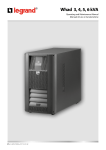
1
V81575A
UPS WHAD
3000 - 4000 - 5000 - 6000
GRUPPO DI CONTINUITA’
UNINTERRUPTIBLE POWER SUPPLY
IT
EN
Manuale d’uso per l’utente
User manual
www.metasystem.it
IT
Dichiarazione
Direttive del consiglio applicate:
Standard al quale si dichiara la conformità:
Costruttore:
Indirizzo:
Tipo di apparecchiatura:
Modelli:
Anno di apposizione del marchio:
di Conformità
73/23/CEE modificata con le direttive 93/68/CEE
89/336/CEE modificata con le direttive 92/31/CEE, 93/68/CEE
EN 62040-1-1, EN 50091-2, EN 62040-3
MetaSystem S.p.A.
via Majakovskij, 10/b Reggio Emilia, Italia
Gruppo di Continuità
WHAD 3000
WHAD 4000
WHAD 5000
WHAD 6000
2007
L’apparecchiatura è stata provata nella configurazione tipica di installazione e con periferiche conformi alle direttive sopra elencate.
Io sottoscritto dichiaro che l’apparato sopra definito soddisfa i requisiti delle Direttive sopra specificate.
Reggio Emilia, 07/05/07
Ing. Cesare Lasagni
Direttore Tecnico
Le informazioni contenute nel presente manuale sono puramente indicative e, con l’obbiettivo di
migliorare il prodotto, possono essere soggette a variazioni senza preavviso.
3
Indice
Indice
1 - Introduzione
5
5
Avvertenze
2 - Funzionamento
Principio di Funzionamento
Funzionamento a rete
Funzionamento a batteria
Funzionamento a By-pass
Segnalazioni ottiche e acustiche
3 - Installazione
Predisposizione all’installazione
Collocazione del Gruppo di Continuità
Pannello Frontale
Procedura d’installazione
Guida all’uso del software autodiagnostico
Accensione
4 - Caratteristiche Tecniche
Specifiche costruttive
Specifiche ambientali
Caratteristiche elettriche d’ingresso
Forma d’onda d’uscita
Caratteristiche elettriche di uscita in funzionamento
a rete
Caratteristiche elettriche di uscita in funzionamento
a batteria
Funzionamento a batteria
Caratteristiche del By-pass
Normative di riferimento
5 - Soluzione ai problemi
6
6
6
6
6
7
8
8
8
9
9
12
12
13
13
13
14
14
14
15
15
15
15
17
4
Introduzione
Vi ringraziamo per l’acquisto di un prodotto MetaSystem. Obiettivo primario della nostra Azienda è di fornire sempre
prodotti all’avanguardia, frutto della ricerca e dell’applicazione delle tecnologie più innovative.
Le nostre apparecchiature sono coperte da numerosi brevetti internazionali, rappresentativi del carattere di
esclusività e continuo miglioramento dell’azienda MetaSystem.
I gruppi di continuità MetaSystem sono stati studiati per proteggere le apparecchiature elettroniche dai problemi
sulla rete elettrica, quali interruzioni, fluttuazioni e disturbi.
In particolare il prodotto da Voi acquistato prevede l’esclusivo “Algoritmo di calcolo State of charge” per ottenere
le migliori prestazioni di autonomia dell’UPS.
La conformità del nostro prodotto agli standard internazionali è ulteriore garanzia di qualità dei nostri prodotti.
Vi consigliamo di leggere attentamente il presente manuale e conservarlo per successive
consultazioni
Avvertenze
• Non collegare carichi superiori ai limiti indicati nella targhetta di identificazione e nella documentazione
a corredo
• Non smontare l’apparecchiatura. L’accesso all’interno del gruppo di continuità è riservato a personale
tecnico autorizzato.
• Non disconnettere la connessione alla tensione di rete con gruppo di continuità funzionante, questa
operazione elimina la protezione di terra per il gruppo di continuità e per i carichi ad esso collegati.
• Non introdurre cacciaviti o altri oggetti nei fori di aerazione o nella ventola.
• Installare l’apparecchiatura secondo quanto descritto nel presente manuale e rispettando i limiti previsti.
• Non versare liquidi sul gruppo di continuità.
• Utilizzare l’apparecchiatura esclusivamente per gli scopi indicati nel presente manuale.
• Il costruttore declina ogni responsabilità per danni causati dall’inosservanza di quanto indicato nel
presente manuale.
Le informazioni contenute nel presente manuale sono puramente indicative e, con
l’obbiettivo di migliorare il prodotto, possono essere soggette a variazioni senza preavviso.
5
2 - Funzionamento
2. Funzionamento
Principio di funzionamento
Il gruppo di continuità segnala all’operatore lo stato di funzionamento mediante
segnalazioni ottiche e acustiche:
- indicatore di stato 2 Pag. 9
- segnalatore acustico (interno al gruppo di continuità)
La combinazione di queste segnalazioni rende rapida e intuitiva l’individuazione dello
stato di funzionamento e di eventuali problemi alla rete di alimentazione.
Sono possibili tre principali modi di funzionamento
- Funzionamento a rete
- Funzionamento a batteria
- Funzionamento in By-pass
Funzionamento a rete
E’ la condizione di normale funzionamento:
- la tensione di rete viene convertita dal regolatore del fattore di potenza (PFC) in tensione
continua
- l’inverter ricostruisce la tensione sinusoidale dalla tensione continua
- il filtro di uscita effettua una ulteriore “pulizia” della tensione di uscita
- le batterie vengono ricaricate
Funzionamento a batteria
Il gruppo di continuità in assenza della tensione di rete, commuta automaticamente nel modo di
funzionamento a batteria.
- la tensione delle batterie viene elevata dal circuito “survoltore”
- l’inverter ricostruisce la tensione sinusoidale dalla tensione continua
- il filtro di uscita garantisce la pulizia della tensione verso il carico
Funzionamento a By-pass
Il circuito di By-pass esclude il gruppo di continuità e collega direttamente l’uscita con l’ingresso. La
commutazione avviene in modo sincronizzato al fine di garantire sempre la corretta tensione di uscita,
evitando interruzioni o sovratensioni.
L’intervento del circuito di By-pass è personalizzabile attraverso un menu dedicato (Config. UPS,
By-pass) e prevede numerose opzioni (automatico, disabilitato, By-pass in attesa carico, etc..) in modo
da rispondere alle specifiche esigenze dell’applicazione.
6
2 - Funzionamento
Segnalazioni ottiche e acustiche
INDICATORE
DI STATO
SEGNALATORE
ACUSTICO
Verde
---
Verde
---
UPS a Rete
IN xxxV/x.xkW
UPS a Rete
Rete non
sincronizzata xx.xHz
Intermittente
rapido
Giallo
Giallo
Intermittente
breve (ogni 20sec)
Intermittente
rapido
DESCRIZIONE
Funzionamento normale con rete
presente e carico entro i limiti
Il gruppo di continuità segnala che la
frequenza della tensione di uscita non è
sincronizzata con la tensione di ingresso. La
causa può essere:
- PLL disabilitato
- Frequenza della tensione di ingresso al di
fuori dei limiti previsti dal UPS
UPS a Batteria
RETE ASSENTE
Funzionamento a batteria
UPS a By-pass
Funzionamento in By-pass
---
Intermittente
rapido
Rosso
MESSAGGI
A DISPLAY
Modulo guasto
ATTENZIONE! SI CONSIGLIA DI SPEGNERE IL
GRUPPO DI CONTINUITA’ E CONTATTARE IL
CENTRO ASSISTENZA
Intermittente
breve e rapido
Sovraccarico
ATTENZIONE! SI CONSIGLIA DI SCOLLEGARE
ALCUNE UTENZE FINO A RIPORTARE
L’ASSORBIMENTO DEL CARICO ENTRO I
LIMITI PREVISTI
Rosso
UPS in errore o è stato rilevato un guasto
ATTENZIONE! SI CONSIGLIA DI SPEGNERE IL
GRUPPO DI CONTINUITA’ E CONTATTARE IL
CENTRO ASSISTENZA
Continuo
Rosso
--Superato il 90% del carico MAX
1 ogni 10 sec.
Rosso
Intermittente
alternato breve,
lungo
Rosso
Intermittente
breve con pausa
Intermittente
alternato breve,
lungo
RISERVA
AUTONOMIA!
Riserva di autonomia. In funzionamento a
batteria
Errato collegamento a batteria
Neutro
FUORI
RIDONDANZA!
L’assorbimento del carico è maggiore della
ridondanza impostata. In caso di guasto non
è garantita la ridondanza delle schede di
potenza
---
7
3 - Installazione
3. Installazione
Predisposizione all’installazione
Verificare che l’imballo sia integro e che il prodotto non abbia subito danni durante il trasporto. In caso di
problemi contattare il vettore.
Verificare il contenuto della confezione:
• Nr.1 gruppo di continuità
• Nr.1 busta contenente accessori e set di viti per la corretta installazione del gruppo.
• Manuale dell’utente
• Garanzia internazionale
Si consiglia di conservare l’imballo originale per eventuale riutilizzo o per rispedire il prodotto in caso di guasto.
Collocazione del Gruppo di continuità
Individuare una superficie piana e solida per il posizionamento del gruppo di continuità.
Attenersi alle seguenti condizioni di installazione (Fig. 1):
- il gruppo di continuità deve essere posizionato in ambienti chiusi: non è progettato per un uso all’esterno.
- Rispettare le condizioni ambientali riportate nel presente manuale.
- Evitare ambienti eccessivamente polverosi, umidi e sottoposti a irraggiamento diretto.
- Evitare ambienti con liquidi infiammabili e/o sostanze corrosive.
- Garantire l’aerazione posizionando l’apparecchiatura almeno 20 cm distante da pareti
- Non coprire le zone di aerazione anteriori, posteriori e laterali.
min 20cm
min 20cm
min 20cm
Fig.1 Collocamento gruppo di continuità
8
3 - Installazione
Pannello frontale
1
2
Fig. 2 Pannello anteriore
1 PULSANTE DI ACCENSIONE E SPEGNIMENTO
2 INDICATORE STATO DI FUNZIONAMENTO (verde/giallo/rosso)
Procedura d’installazione
8
Connessioni elettriche
7
6
3 Connettore Ingresso/Uscita
4 Spina Ingresso/Uscita
5
6
7
8
Fusibile d’Ingresso
Presa per Interfaccia seriale RS232 (9 P femm)
Presa a segnali Logici ( 9 P maschio)
Interfaccia SNMP
4
5
3
Fig. 3 Connessioni Elettriche
9
3 - Installazione
UPS Whad 3000 - 4000
1. Cablare il connettore di Ingresso-Uscita in dotazione come
indicato in figura 3, utilizzando un cavo inguainato con
conduttori interni aventi sezione di almeno 2,5 mm2.
2. Inserire il connettore nel coperchio in plastica fissandolo
con le apposite viti, quindi assicurare i cavi al coperchio
tramite il fermacavo (vedi fig. 4).
3. Rimuovere la copertura della spina [4] togliendo la vite di
fissaggio.
4. Collegare il connettore di Ingresso-Uscita alla spina [4]
presente sul retro dell’UPS, fissandolo al telaio con le
apposite viti (vedi fig. 3).
5. Collegare i carichi alla presa di uscita, verificando che gli
interruttori dei vari utilizzatori siano spenti.
6. Collegare la spina di alimentazione ad una presa di
corrente adeguata alla tensione e alla corrente richieste.
Fig. 4 Coperchio morsettiera
AVVERTENZA
i
L’UPS é dotato di un circuito di protezione contro un eventuale errore di collegamento, segnalato all’accensione del
segnalatore visivo di colore rosso acceso fisso e dal suono continuo del buzzer interno. Nel caso si verificasse questa
segnalazione subito dopo l’accensione dell’UPS, spegnere l’apparecchiatura e disconnettere immediatamente la spina
di alimentazione.
Precauzioni per l’installazione
•
•
•
•
i
Si consiglia di far eseguire gli allacciamenti elettrici da personale specializzato
Non modificare i cablaggi elettrici forniti a corredo
Assicurarsi che la presa di rete sia fornita di un buon collegamento di terra
La connessione alla rete o il sezionatore di rete devono essere in prossimità del gruppo di continuità ed
essere facilmente accessibili
ATTENZIONE
(per i modelli 3000/4000)
Poichè le correnti di dispersione verso terra di tutti i carichi si sommano nel conduttore di protezione (filo
di terra) dell’UPS, per motivi di sicurezza, come da norma EN 50091-1-1, occorre assicurarsi che la somma
di queste correnti non superi il valore di 2.7 mA.
Fig. 5 Morsettiera
10
3 - Installazione
UPS Whad 5000 - 6000
1. Cablare il connettore di Ingresso-Uscita in dotazione come
indicato in figure 4-5, utilizzando un cavo inguainato con
conduttori interni aventi sezione di almeno 4 mm2.
Collegare i carichi verificando che gli interruttori dei vari
utilizzatori siano spenti.
2. Inserire il connettore nel coperchio in plastica fissandolo
con le apposite viti, quindi assicurare i cavi al coperchio
tramite il fermacavo (vedi fig. 6).
3. Rimuovere la copertura della spina [4] togliendo le viti di
fissaggio.
4. Inserire il connettore di Ingresso-Uscita [3] nella spina [4]
presente sul retro dell’UPS, assicurando il collegamento
inserendo i quattro fissaggi di colore arancione negli appositi
spazi presenti nella spina [4]
5. Fissare il coperchio in plastica al telaio con le apposite viti
(vedi fig. 3).
!
Fig. 6 Coperchio morsettiera
ATTENZIONE
I gruppi UPS Whad 5000 - 6000 non presentano il circuito di Back Feed Protection
1. L’installazione dei gruppi UPS Whad 5000 - 6000 dovrà essere solamente di tipo fisso con un sezionatore bipolare a monte.
Non è ammesso il collegamento del gruppo alla rete mediante spina.
2. Si dovrà apporre un etichetta di avvertimento posta su tutti i sezionatori della potenza di rete installati lontanto dall’area
dell’UPS allo scopo di richiamare il personale di assistenza sul fatto che il circuito è collegato a un UPS. L’etichetta deve riportare
il testo seguente o equivalente:
ISOLARE IL SISTEMA DI CONTINUITA’ (UPS) PRIMA DI OPERARE SU QUESTO CIRCUITO.
AVVERTENZA
!
L’UPS é dotato di un circuito di protezione contro un eventuale errore di collegamento, segnalato all’accensione del
segnalatore visivo di colore rosso acceso fisso e dal suono continuo del buzzer interno. Nel caso si verificasse questa
segnalazione subito dopo l’accensione dell’UPS, spegnere l’apparecchiatura e disconnettere immediatamente la spina
di alimentazione.
Precauzioni per l’installazione
• Si consiglia di far eseguire gli allacciamenti elettrici da personale specializzato
• Assicurarsi che la rete sia fornita di un buon collegamento di terra
• La connessione al sezionatore di rete deve essere in prossimità del gruppo di continuità ed essere
facilmente accessibile
Fig. 7 Morsettiera
11
3 - Installazione
Guida all’uso del Software autodiagnostico
Connessione
L’UPS è dotato di interfaccia standard RS232, grazie alla quale è possibile accedere, tramite un elaboratore, ad una
serie di dati relativi al funzionamento e alla storia dell’UPS. La funzione è utilizzabile tramite il programma di
interfacciamento per ambiente WINDOWS disponibile gratuitamente sul sito www.metasystem.it, connettendo una
porta seriale del PC alla presa di interfacciamento [6] presente sul retro dell’UPS, tramite un cavo RS232.
Accensione
1) Accendere il gruppo di continuità con l’apposito pulsante [1]; inizialmente l’UPS alimenterà l’uscita direttamente
dalla rete tramite il by-pass (segnalazione del indicatore di stato di colore giallo [2]) per poi commutare a inverter
dopo alcuni secondi ed entrare nel modo normale di funzionamento (indicatore di stato verde [2]).
2) Accendere i carichi e verificare che, dopo l’eventuale intervento del by-pass, si abbia il ritorno al funzionamento
normale; a questo punto è acceso l’indicatore di stato di colore verde [2]. Nel caso i carichi collegati risultino
eccessivi, rimarrà inserito il by-pass e lampeggerà l’indicatore di stato di colore rosso [2] in modo rapido.
3) Qualche istante dopo l’accensione, il gruppo di continuità esegue automaticamente il test delle batterie, per
verificarne il corretto funzionamento (vedi paragrafo “Test Batterie”).
12
4 - Caratteristiche tecniche
4. Caratteristiche Tecniche
Specifiche Costruttive
Pesi (Kg.)
Dimensioni
(LxHxP)
Tecnologia
Interfaccia
computer
Protezioni
By-pass
sincronizzato
WHAD
3000
WHAD
4000
WHAD
5000
WHAD
6000
55
55
65
65
270 x 475 x 570 mm
PWM ad alta frequenza sia per lo stadio di ingresso che per quello di uscita.
Logica di controllo a microprocessore
A livelli logici, per interfacciamento con kit opzionali. Uscita su connettore a vaschetta 9 poli maschio,
isolato SELV. Seriale RS232 standard per interfacciamento con personal computer tramite software di
shutdown autodiagnostico. Uscita su connettore a vaschetta 9 poli femmina isolato SELV.
Interfaccia SNMP.
Elettroniche contro sovraccarichi, cortocircuito ed eccessiva scarica delle batterie. Blocco del funzionamento
per fine autonomia. Limitatore di spunto all’accensione. Sensore di corretto collegamento del neutro. Backfeed protection (isolamento elettrico di sicurezza della spina d’ingresso durante il funzionamento a batteria).
Contatto EPO per collegamento “fungo VVF”
Statico automatico e manuale (optional).
Intervento per sovraccarico o anomalia di funzionamento.
Specifiche Ambientali
Altitudine max
immagazzinamento
10.000 metri
Gamma
temperature
da -20° C a +50° C
immagazzinam.
Gamma
temperature
da 0° C a +40° C
funzionamento
Gamma umidità
relativa funzion.
20-80% non condensante
Grado di
protezione
(IEC529)
IP 21
Rumore acustico
ad 1mt.
(<) 40dB A
13
4 - Caratteristiche tecniche
Caratteristiche Elettriche d’ Ingresso
WHAD
4000
WHAD
3000
WHAD
5000
Tensioni nominali
d’ingresso
230 V
Gamma tensione
ingresso
Frequenza
nom.ingresso
Corrente massima
d’ingresso
WHAD
6000
da 184V a 264V con carico nom. - da 100V a 264V al 50% del carico nom.
50 Hz o 60 Hz +2% (autosensing e/o selezionabile dall’utente)
13A rms
Distorsione
corrente d’ingresso
Fattore di potenza
d’ingresso
18A rms
22A rms
THD
27A rms
< 3%
> 0,99 dal 20% del carico nominale
Corrente di spunto
100% della corrente nominale
Numero fasi
d’ingresso
Monofase
Forma d’Onda d’Uscita
In funzionamento
a rete
In funzionamento
a batteria
Tipologia di
funzionamento
Sinusoidale
Sinusoidale
Gruppo di continuità di tipo no-break, on-line, doppia conversione con neutro passante
Caratteristiche Elettriche di Uscita in Funzionamento a Rete
Tensione nominale
d’uscita
Frequenza
nominale d’uscita
Corrente max d’uscita
su carico lineare fattore
di potenza 0,7
230 V ± 1%
50 Hz / 60Hz sincronizzata (autosensing e/o selezionabile dall’utente)
13A rms
18A rms
Fattore di cresta
sulla corrente
d’uscita
Potenza nominale
d’uscita
Potenza attiva
d’uscita sucarico
lineare o non lineare
P.F. 0,7
22A rms
27A rms
3,5
3000VA
4000VA
5000VA
6000VA
2100W
2800W
3500W
4200W
Capacità di
sovraccarico
150% per 30 secondi senza intervento del By-pass
N.ro delle fasi
d’uscita
Monofase
14
4 - Caratteristiche tecniche
Caratteristiche Elettriche di Uscita in Funzionamento a Batteria
WHAD
4000
WHAD
3000
Tensione nominale
d’uscita
Frequenza
nominale d’uscita
Corrente max d’uscita
su carico lineare fattore
di potenza 0,7
230 V ± 1%
50 Hz / 60Hz ± 1% (autosensing e/o selezionabile dall’utente)
13A rms
18A rms
22A rms
27A rms
3000VA
4000VA
5000VA
6000VA
2100W
2800W
3500W
4200W
Potenza nominale
d’uscita
Potenza attiva
d’uscita sucarico
lineare o non lineare
P.F. 0,7
N.ro delle fasi
d’uscita
!
WHAD
6000
WHAD
5000
Monofase
ATTENZIONE: Pericolo di esplosione se la batteria è sostituita con un’altra di tipo scorretto. Eliminare le
batterie usate seguendo le istruzioni e precauzioni di smaltimento indicate sulle stesse.
Funzionamento a Batteria
Autonomia
indicativa in minuti
con batterie
cariche
Carico applicato in
percentuale
80%
100%
80%
100%
80%
100%
80%
100%
UPS Standard
15
10
11
8
15
10
11
8
Tempo di ricarica
fino al 90% della
carica totale
Dati tecnici e
quantità delle
batterie
Tempo medio di
vita delle batterie
8 ore a seconda del livello di scarica raggiunto
n. 12 batterie piombo-acido sigillate senza manutenzione 12V
7,2Ah connesse in serie.
n. 16 batterie piombo-acido sigillate senza manutenzione 12V
7,2Ah connesse in serie.
3-6 anni a seconda dell’utilizzo e della temperatura di esercizio.
Attenzione!
Le batterie contenute nell’UPS, sono soggette ad una diminuzione di capacità in funzione del tempo di vita
(caratteristica propria della batterie al piombo dichiarata dal costruttore del manuale tecnico). Ad esempio, la
diminuzione di capacità di una batteria con 4 anni di vita può arrivare fino al 40% con conseguente calo
proporzionale dei tempi di autonomia dell’UPS in funzionamento a batteria.
Caratteristiche del By-pass
Tipo di bypass
Statico ed elettromeccanico
Tempo di
commutazione
nullo
15
4 - Caratteristiche tecniche
Normative di riferimento
WHAD
4000
WHAD
3000
Sicurezza:
progettato per
soddisfare la
norma
Compatibilità
elettromagnetica:
•immunità
•emissioni
Prestazioni
caratteristiche
WHAD
5000
WHAD
6000
Rispondente alla normativa EN 62040-1-1
Rispondente alla normativa EN 50091-2
Rispondente alla normativa EN 50091-2
(classe A)
(classe B)
Rispondente alla normativa EN 62040-3
Dati e caratteristiche tecniche possono essere variati da MetaSystem senza preavviso
MANUTENZIONE PERIODICA
Pulizia
Prima di effettuare le operazioni di pulizia si raccomanda di:
- Spegnere le apparecchiature collegate al gruppo di continuità
- Scollegare le apparecchiature dal gruppo di continuità
- Scollegare la rete dal gruppo di continuità
Pulizia esterna
- Pulire utilizzando un panno morbido e asciutto
Pulizia delle aperture di raffreddamento
- Eseguire periodicamente la pulizia delle aperture di raffreddamento, aspirando o utilizzando un pennello morbido
16
5 - Soluzione ai problemi
5. Soluzione ai problemi
Problemi
Soluzioni
All’accensione l’UPS fa suonare il cicalino e
lampeggiare il segnalatore visivo rosso con
intermittenza di tipo alternato breve-lungo, quindi
si spegne dopo 15 secondi.
È errato il collegamento del conduttore di neutro:
girare la spina di alimentazione, oppure invertire il
senso di collegamento dei cavi di neutro e fase di
ingresso, oppure escludere sensore di neutro.
L’UPS funziona ma ogni 12 secondi emette un
breve segnale acustico ed é sempre acceso il
segnalatore visivo giallo BATTERY.
- Assicurarsi della presenza di tensione nella
presa di rete.
- Controllare il perfetto inserimento del cavo di
alimentazione del gruppo di continuità sia nella
presa di rete che nel connettore del gruppo
stesso.
- Verificare lo stato del fusibile che si trova di
fianco al connettore di ingresso/uscita sotto il
coperchio in plastica (vedi figura 1 o 4).
L’UPS funziona ma emette un segnale acustico
intermittente e lampeggia il segnalatore visivo
rosso + giallo By-pass.
È presente un sovraccarico dell’uscita dell’UPS.
Ridurre il numero di apparecchiature collegate in
modo che il carico non superi la massima potenza
erogabile dal gruppo di continuità. In alternativa,
se non si è già in configurazione massima, è
possibile richiedere al Centro Assistenza Tecnica
di aumentare la potenza del gruppo aggiungendo,
all’interno dell’UPS, uno o più moduli con le
relative batterie.
L’UPS emette un segnale acustico costante ed é
acceso il segnalatore visivo giallo lampeggiante
per circa 15 secondi, dopo di che il gruppo si
spegne.
Il gruppo ha scaricato completamente le batterie,
può ripartire solo se la linea d’ingresso è
presente. Controllare gli interruttori magnetotermici o differenziali a monte del gruppo e il
fusibile d’ingresso
L’UPS funziona ma il segnalatore visivo verde La rete è fuori dai limiti consentiti come tensione
MAINS lampeggia in modo rapido.
e/o come frequenza, ma pur sempre utilizzabile
dall’UPS. Non è però disponibile la funzione di
By-pass.
L’UPS emette un segnale acustico intermittente e
il segnalatore visivo rosso lampeggia in modo
rapido.
È intervenuta la protezione termica. Spegnere il
gruppo di continuità e attendere qualche minuto in
modo che la temperatura interna dell’UPS si
normalizzi. Verificare il corretto funzionamento delle
ventole e che il relativo flusso d’aria non sia
ostacolato (ad es. gruppo troppo vicino ad una
parete).
È avvenuto un guasto in qualche circuito interno.
Contattare il centro di assistenza.
Se il problema persiste contattare il centro assistenza MetaSystem al numero verde:
Numero Verde
800-005088
17
EN
Certification of
Directives applied:
We certify conformity to standards:
Manufacturer:
Address:
Type of appliance:
Models:
Year of application:
conformity
73/23/EEC modified with directives 93/68/EEC;
89/336/EEC modified with directives 92/31/EEC, 93/68/EEC
EN 62040-1-1, EN 50091-2, EN 62040-3
MetaSystem S.p.A.
via Majakovskij, 10/b Reggio Emilia, Italy
Uninterruptible Power Supply
WHAD 3000
WHAD 4000
WHAD 5000
WHAD 6000
2007
The appliance was tested in the typical configuration for its installation and with peripherals in compliance with the above Directives.
The undersigned certifies that the above appliance satisfies the requirements of the specified Directives.
Reggio Emilia, 07/05/07
Ing. Cesare Lasagni
Technical Manager
All the information contained in this manual is provided as a guide and is subject to change
without notice for product upgrading.
18
Index
Index
1 - Introduction
20
20
Important information
2 - Operation
Operating principle
Mains operation
Battery operation
By-pass operation
Visual and acoustic warning signals
3 - Installation
Prior to installation
Where to install your UPS
Front panel
Installation procedure
Guide to using the diagnostics software
Switching on
4 - Specifications
Construction specifications
Environmental specifications
Electrical input specifications
Output waveform
Electrical output specifications when running on
mains power
Electrical output specifications when running on
battery power
Battery operation
By-pass specifications
Reference standards
5 - Troubleshooting
21
21
21
21
21
22
23
23
23
24
24
27
27
28
28
28
29
29
29
30
31
31
31
33
19
Introduction
Thank you for choosing to purchase a MetaSystem product. Our company’s main objective is to supply innovative
products that are the outcome of our ongoing research and application of cutting-edge technology.
Our products are covered by several international patents, emblematic of MetaSystem’s quest for exclusivity and
ongoing improvement.
MetaSystem uninterruptible power supplies are designed to protect electronic equipment from problems that may be
encountered with your mains electricity supply, such as power cuts, surges and interference.
In particular, the product you have purchased is enhanced with our exclusive “State of Charge Algorithm” which makes
it possible for your UPS to achieve the best possible performance in terms of autonomy.
Our products comply with international standards: an additional guarantee of the quality of our products.
We recommend you read this manual carefully and keep it for future reference.
Important information
• Do not connect loads in excess of the limit stipulated on the product’s label and in the relative documents
provided.
• Do not dismantle the UPS. Only authorised technical personnel are allowed access to the internal parts
of the UPS.
• Never disconnect the UPS from the mains power supply when it is running: this would cut off the earth
protection of both the UPS and of the loads connected to it.
• Do not insert screwdrivers or other items inside the ventilation holes or into the fan.
• The UPS must be installed according to the instructions in this manual and in compliance with the set
limits.
• Take care that no liquids come into contact with your UPS.
• This product should only be employed for the designated uses described in this manual.
• The manufacturer is not liable for any damage or injury caused by failure to comply with the instructions
in this manual.
All the information contained in this manual is provided as a guide and is subject to change
without notice for product upgrading.
20
2 - Operation
2. Operation
Operating procedure
The UPS keeps the operator informed regarding its operating status using visual and acoustic signals:
- status indicator 2 on page 24
- acoustic signal (located inside the UPS)
The combination of these signals enables rapid and intuitive understanding of its operating status and
recognition of any problems in the power supply.
There are three main operating modes
- Mains operation
- Battery operation
- By-pass operation
Mains operation
This is considered the normal operating condition:
- mains voltage is converted by the power factor corrector (PFC) into continuous current
- the inverter reconstructs the sinusoidal voltage from the continuous current
- the output filter provides extra “cleaning” of the output voltage
- the batteries are recharged
Battery operation
When there is a mains power failure, the UPS automatically switches over to battery mode.
- the voltage of the batteries is increased by the “booster” circuit
- the inverter reconstructs the sinusoidal voltage from the continuous current
- the output filter ensures the voltage supplied to the load is clean
By-pass operation
The by-pass circuit excludes the UPS and connects the output directly to the input. The switchover takes
place in a synchronised manner in order to ensure the correct output voltage is always guaranteed,
preventing the risk of a break in power or excess voltage.
The intervention of the by-pass circuit can be customised by means of a dedicated menu (Config. UPS,
By-pass) which provides many options (automatic, disabled, by-pass in load waiting mode, etc.) in order to
meet the specific demands of the application.
21
2 - Operation
Visual and acoustic warning signals
STATUS
INDICATOR
ACOUSTIC
SIGNAL
Green
---
Green
---
Fast flashing
Yellow
Yellow
Short intermittent
sound (every 20sec)
Fast flashing
DESCRIPTION
UPS on Mains
IN xxxV
Normal operation with mains present and
loads within the set limits
UPS on Mains
No sync mains
xx.xHz
The UPS is indicating that the frequency of
the output voltage is not synchronised with
the input voltage. The cause of this may be:
- PLL disabled
- Frequency of the input voltage is outside the
set limits for the UPS
UPS on Batteries
MAINS ABSENT
Battery operation
UPS on Bypass
By-pass operation
---
Fast flashing
Red
MESSAGES
DISPLAYED
Module failure
ATTENTION! WE RECOMMEND YOU SWITCH
OFF THE UPS AND CONTACT YOUR SERVICE
CENTRE
Short and fast
intermittent sound
Overload
ATTENTION! WE RECOMMEND REMOVING
SOME OF THE APPLIANCES CONNECTED TO
THE UPS SO THAT CONSUMPTION BY THE
LOAD RETURNS BELOW SET LIMITS
Red
Red
UPS error or failure
ATTENTION! WE RECOMMEND YOU SWITCH
OFF THE UPS AND CONTACT YOUR SERVICE
CENTRE
Continuous sound
--Above 90% of MAX load
1 flash every 10
secs.
Red
Alternating short
long flashing
Red
Short flashing
with pause
Alternating short,
long intermittent
sound
RESERVE
AUTONOMY!
--OUT OF
REDUNDANCY!
22
Autonomy reserve. During battery
operation
Incorrect battery connection
Incorrect Neutral
Consumption by the load is above the
redundancy that has been set. Power board
redundancy is not guaranteed in case of
failure
3 - Installation
3. Installation
Prior to installation
Check the packaging has not been opened or damaged and that the product has not been damaged during
transport. Please contact your shipping agent in case of doubt.
Check the contents of the box:
• Nr.1 UPS
• Nr.1 connector for the input/output cable (single cabinet version includes multiple output socket and
input cable)
• Instructions manual
We recommend you keep the equipment’s packaging materials as they can be useful should the need arise to send the product
back for repairs.
Where to install your UPS
Make sure the place where you intend installing your UPS is level and sturdy.
Please comply with the following requisites for installation (Fig. 1):
- The UPS must be located in an enclosed environment: it was not designed to operate out of doors.
- It is essential that you comply with the environmental conditions illustrated in this manual.
- Avoid placing it in very dusty or damp areas or in direct sunlight.
- Avoid places where there are inflammable liquids and/or corrosive substances.
- Ventilation must be guaranteed by placing the UPS at least 20 cm away from any walls
- Do not cover the ventilation outlets on the front, rear or sides of the UPS
min 20cm
min 20cm
min 20cm
Fig.1 Where to install the UPS
23
3 - Installation
Front panel
1
2
Fig. 2 Front Panel
1 BUTTON TO SWITCH ON / SWITCH OFF
2 MULTICOLOUR OPERATING STATUS INDICATOR LIGHT (GREEN / YELLOW / RED)
Installation procedure
8
Electrical connections
7
6
Single Cabinet (fig. 2):
3
4
5
6
7
8
Input/Output connector
Input/Output plug
Input fuse
RS232 serial interface outlet (9-pin female)
Logic signals outlet (9-pin male)
SNMP Interface
4
5
3
To the loads
To the mains
electricity supply
Fig. 3 Electrical Connections
24
3 - Installation
Single cabinet
INPUT-OUTPUT
h h CONNECTOR
Assembly
1. Wire up the Input-Output connector supplied as shown in
figure 4, using insulated cable with wires whose section is at
least 2.5 mm2.
2. Insert the connector into the plastic housing and secure it
using the screws supplied. Secure the wires to the housing
using the cable grip (see fig. 4).
3. Take the cover off the plug [4] by removing its screws.
4. Put the Input-Output connector into the plug [4] located on
the rear of the UPS, and secure to its case using the screws
supplied (see fig. 3).
5. Check that the on/off switches of all the appliances to be
connected to the UPS are OFF and connect them to the output
socket.
6. Insert the power supply plug into a power outlet that is
adequate for the voltage and current required.
i
°
CONNECTOR
Reference
h notch
h
PLASTIC HOUSING
h h
CABLE GRIP
Fig. 4 Connection terminals housing
WARNING
Your UPS is fitted with a circuit to protect it against the risk of incorrect connections. This eventuality will be indicated
by means of its red warning light, lit without flashing, and the continuous sounding of its internal buzzer. Should you
note this signal immediately after switching the UPS on, switch it off and remove the power supply plug immediately.
Precautions for installation
•
•
•
•
Electrical connections should only be done by trained personnel
Do not modify the electric cables supplied
Make sure that the mains outlet is connected securely to an earth circuit
The mains outlet, or the circuit breaker, must be installed near the appliance and must be easily
accessible
ATTENTION
i (for versions 3000/4000)
Since current dispersion towards earth of all the loads merges in the UPS protection wire (earth wire), it is
essential to check that the sum of these currents does not exceed 2.7 mA, according to standard EN
50091-1-1, for safety reasons.
INPUT-OUTPUT CONNECTOR
Side with insertion of wires
Earth connection
Yellow-green wire
Brown wire
Blue wire
Yellow-green wire
Blue wire
Brown wire
Input cable
(to the mains
electricity supply)
Output cable
(to load)
Terminal n°1 PHASE OUTPUT
Terminal n°2 NEUTRAL OUTPUT
Terminal n°3 NEUTRAL OUTPUT
Terminal n°4 PHASE OUTPUT
Fig. 5 Terminals
25
3 - Installation
Single cabinet UPS What 5000 - 6000
INPUT-OUTPUT CONNECTOR
Assembly
1. Wire up the Input-Output connector supplied as shown in
figure 6-7, using insulated cable with wires whose section is
at least 4 mmq. Check that the on/off switches of all the
appliances to be connected to the UPS are OFF.
2. Insert the connector into the plastic housing and secure it
using the screws supplied. Secure the wires to the housing
using the cable grip (see fig. 6).
3. Take the cover off the plug [4] by removing its screws.
4. Put the Input-Output connector [3] into the plug [4] located
on the rear of the UPS, and secure to the plug using the
orange flanges for secure.
5. Secure the plastic housing to the rear of the UPS the
screws supplied (see fig. 3).
Reference
notch
Plastic Housing
Cable grip
Fig. 6 Connection terminals housing
WARNING
!
UPS What 5000 - 6000 don’t have internal automatic back feed protection.
1. The WHAD series of UPS must be permanently connected. An appropriate and accessible disconnect device shall be
incorporated in the fixed wiring. It's forbidden to connect the UPS to mains power using a traditional plug.
2. A warning label shall be fit on all primary power isolators installed remote from the UPS area in order to warn electrical
maintenance personnel that the circuit feeds an UPS. The warning label shall carry the following wording or equivalent:
ISOLATE UNINTERRUPTIBLE POWER SUPPLY (UPS)
BEFORE WORKING ON THIS CIRCUIT
!
WARNING
Your UPS is fitted with a circuit to protect it against the risk of incorrect connections. This eventuality will be indicated
by means of its red warning light, lit without flashing, and the continuous sounding of its internal buzzer. Should you
note this signal immediately after switching the UPS on, switch it off and remove the power supply plug immediately.
Precautions for installation
• Electrical connections should only be done by trained personnel
• Make sure that mains is connected securely to an earth circuit
• The circuit breaker must be installed near the appliance and must be easily accessible
INPUT-OUTPUT CONNECTOR
Fig. 7 Terminals
Side with insertion of wires
Input cable
(to the mains
electricity supply)
Output cable
(to load)
Terminal n°2: Neutral Output
Terminal n°3: Earth Output
Terminal n°4: Phase Output
Terminal n°5: Neutral Input
Terminal n°6: Earth Input
Terminal n°7: Phase Input
26
3 - Installation
Guide to using the diagnostics software
Connection
Your UPS is fitted with a standard RS232 interface, which can be used in conjunction with a computer in order to
access data relating to the operation of the UPS and its log. This function must be used together with the interface
programme for WINDOWS environments available from our website www.metasystem.it without charge. A RS232
cable is required to connect a serial port on your PC to the interface outlet [6] located on the rear of the UPS.
Switching on
1) Switch the UPS on with the appropriate button (1).
The UPS initially supplies the output directly with mains power using its bypass (signalled by the yellow Status
Indicator) (2) and after a few seconds switches over to its inverter and enters its normal operation mode (the
green Status Indicator [2] is on).
2) Switch the connected loads on and, after any bypass intervention, check that normal operation is resumed: at this
point the green Status Indicator [2] is on. Should the connected loads be too large, the bypass will remain active
and the red Status Indicator [2] will flash fastly.
3) A few moments after switching on, the UPS will automatically test its batteries to check if they are operating
correctly (refer to the section on the ‘Battery Test’).
27
4 - Specifications
4. Specifications
Construction specifications
Weight (Kg.)
WHAD
3000
WHAD
4000
WHAD
5000
WHAD
6000
55
55
65
65
Size
(LxHxP)
270 x 475 x 570 mm
Technology
PWM high frequency both for input stage and output stage. Microprocessor control logic
Computer
Interface
With logic levels, to interface with optional kits. Output with 9-pin male, SELV insulated connector.
Standard serial RS232 for interfacing with personal computer using diagnostics software. Output with 9pin, female, SELV insulated, connector.
Protection
Electronic protection against overloads, short circuits and excessive battery discharge. Operation blocked at
end of autonomy. Inrush limitation when switching on. Sensor for correct neutral connection. Back-feed
protection (electrical insulation for the safety of the input plug when running in battery mode). EPO contact
(emergency power off)
Synchronised
By-pass
Automatic static and manual (optional).
Intervenes in case of overload and operating anomaly.
Environmental specifications
Maximum altitude
for storage
Storage
temperature
range
Operating
temperature
range
Range of relative
humidity for
operating
10.000 metres
from -20° C to +50° C
from 0° C to +40° C
20-80% non condensing
Grade of
protection
(IEC529)
IP 21
Noise level
at 1 metre
(<) 40dB A
28
4 - Specifications
Electrical input specifications
WHAD
3000
WHAD
5000
WHAD
4000
Nominal input
voltage
Input voltage
range
Nominal input
frequency
Maximum input
current
WHAD
6000
230 V
from 184V to 264V with nom. load – from 100V to 264V with 50% of nom. load
50 Hz or 60 Hz +/-2% (autosensing and/or as selected by operator)
13A rms
18A rms
Distortion of input
current
Input power
factor
22A rms
THD
27A rms
< 3%
> 0,99 dal 20% of nominal load
In-rush current
100% of nominal current
Number of input
phases
Single phase
Output waveform
With mains
operation
Sine wave
With battery
operation
Sine wave
Type of
operation
No break, on line UPS with passing neutral and double conversion
Electrical output specifications when running on mains power
Nominal output
voltage
Nominal output
frequency
Output current with
linear load and
power factor 0,7
230 V ± 1%
50 Hz / 60Hz synchronised (autosensing and/or as selected by operator)
13A rms
18A rms
Crest factor on
output current
22A rms
27A rms
3,5
Nominal output
power VA
3000VA
4000VA
5000VA
6000VA
Active output power
with linear or nonlinear load P.F. 0,7
2100W
2800W
3500W
4200W
Overload
capacity
150% for 30 seconds without By-pass intervention
Number of output
phases
Single phase
29
4 - Specifications
Electrical output specifications when running on battery power
WHAD
3000
Nominal output
voltage
Output
frequency
WHAD
5000
WHAD
4000
WHAD
6000
230 V ± 1%
50 Hz / 60Hz ± 1% (autosensing and/or as selected by operator)
Nominal output
power VA
Active output power
with linear or nonlinear load P.F. 0,7
3000VA
4000VA
5000VA
6000VA
2100W
2800W
3500W
4200W
Number of output
phases
!
Single phase
ATTENTION: There is a danger of explosion should the batteries be replaced with the wrong type.
Dispose of used batteries as per the instructions and precautions for their disposal on the battery label!
30
4 - Specification
Battery operation
WHAD
3000
WHAD
6000
WHAD
5000
WHAD
4000
Approximate
autonomy in
minutes with
charged batteries
Percentage of
applied load
80%
100%
80%
100%
80%
100%
80%
100%
Standard UPS
15
10
11
8
15
10
11
8
Recharge time up to
90% of total charge
Specifications and
quantity of
batteries
Average battery
life
8 hours according to level of discharge
n. 12 pcs 12V 7,2Ah, sealed, lead-acid, maintenance free batteries
connected in series
n. 16 pcs 12V 7,2Ah, sealed, lead-acid, maintenance free batteries
connected in series
3-6 years according to use and working temperature
Warning!
The batteries in the UPS are subject to a reduction in capacity depending on their age (a feature of lead batteries
declared by their manufacturer in the technical manual). For example, the reduction of capacity of a 4-year-old
battery can be as much as 40%, resulting in a proportional reduction of UPS autonomy time when running on
battery power.
By-pass Specifications
Type of by-pass
Static and electromechanical
Switchover time
zero
Reference Standards
Safety:
Designed to
satisfy standard
Electromagnetic
compatibility:
•immunity
•emission
Typical
performance
Conforms to standard EN 62040-1-1
Conforms to standard EN 50091-2
Conforms to standard EN 50091-2
(class A)
(class B)
Conforms to standard EN 62040-3
31
4 - Specifications
MetaSystem reserves the right to vary data and specifications without notice
ROUTINE MAINTENANCE
Cleaning
Before cleaning, it is essential to verify the following:
- all appliances connected to the UPS have been switched off
- all the appliances have been disconnected from the UPS
- the UPS has been disconnected from the mains power supply
Cleaning the cabinet
- Clean with a soft dry cloth
Cleaning the air vents
- Clean the air vents regularly by vacuuming them or using a soft brush
32
5 - Troubleshooting Guide
5. Troubleshooting
Problems
Solutions
When the UPS is switched on, the buzzer sounds
and the red warning light makes alternating
short-long flashes, then the UPS switches off
after 15 seconds
The connection of the neutral conductor is wrong:
invert the power supply plug, or invert the
connections of the neutral and phase input leads,
or exclude the neutral sensor.
The UPS works but a short beep is heard every
12 seconds and the yellow warning light is lit
without flashing.
The UPS works but it beeps intermittently and the
red warning light and the yellow warning light are
flashing.
The UPS beeps continuously and the yellow
warning light flashes for about 15 seconds, after
which the UPS switches off
- Check power is present at the mains outlet.
- Check that the UPS power supply cable is
correctly inserted in both the mains outlet and in
the connector on the UPS itself.
- Check the fuse located at the side of the
input/output connector under the plastic
housing (refer to fig.1 or 4)
There is an overload on the UPS output. Reduce
the quantity of appliances connected so that the
load does not exceed the maximum power that
the UPS can supply. Alternatively, if the UPS is not
in its maximum configuration, you can ask your
Service Centre to increase the power of your UPS
by fitting extra power boards and relative batteries
inside the UPS cabinet.
The UPS has completely flattened its batteries; it
can only start up again when the mains input line
is present. Check the magneto-thermal or
differential switches that precede the UPS and
the input fuse
The UPS works but the green warning light is The mains supply is out of the limits permitted for
flashing quickly
the voltage and/or frequency, but it can still be
used by the UPS. However, the by-pass function is
not operational
The UPS beeps intermittently and the red warning
light is flashing quickly.
33
The thermal protection has been tripped. Switch the
UPS off and wait for a few minutes so that the
internal temperature of the UPS can get back to
normal. Check that the fans operate correctly and
that the relative airflow is not obstructed (e.g. if the
UPS is too close to a wall).
There is a fault on one of the internal circuits.
Contact your service centre.
CENTRO ASSISTENZA TECNICA
Numero Verde
800-005088
www.metasystem.it
MetaSystem S.p.A. Via Galimberti,8 - 42100 Reggio Emilia
Tel. +39 0522 364.111 Fax +39 0522 308.382