1
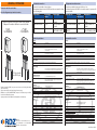
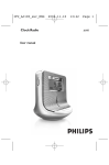
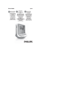
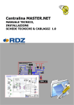
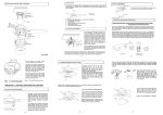
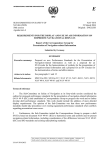
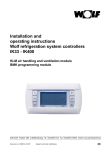
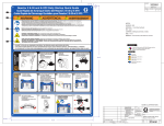
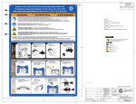
IU-PRO
TECHNICAL SHEET
PRO USER INTERFACE
SCHEDA TECNICA
INTERFACCIA UTENTE PRO
Cod. 6610165
GB
IU-PRO display is an electronic device which makes it possible for end user to
interact with the control system.
The terminal offers a wide range of functioning temperature (-20T60 °C).
Mouting
Fig. 1
Fig. 2
Dimensions / Dimensioni
The wall-mounting of the terminal first requires the back piece of the container
A (Fig. 2) to be fitted, using a standard three-module switch box.
• Fasten the back piece to the box using the rounded-head screws supplied
in the packaging;
• Connect the telephone cable with 6-pole RJ12 connector;
• Rest the front panel on the back piece and fasten the parts together using
the flush-head screws supplied in the packaging, as shown in Fig. 2;
• Finally, fit the click-on frame.
82
31
Fig. 3
Il display grafico IU-PRO è un dispositivo elettronico che consente
all’utente finale di interagire con il sistema di controllo.
Il terminale offre un ampio range di temperatura di funzionamento
(-20T60 °C).
Montaggio
Il montaggio a parete del terminale prevede l’iniziale fissaggio del
retrocontenitore A (Fig. 2), per mezzo di una scatola standard a 3 moduli
per interruttori.
• Fissare il retrocontenitore alla scatola tramite le viti a testa bombata
presenti all’interno dell’imballo;
• Effettuare il collegamento del cavo telefonico con connettore RJ12 a
6 poli;
• Appoggiare il frontale al retrocontenitore e fissare il tutto utilizzando le
viti a testa svasata presenti all’interno dell’imballo come illustrato in Fig. 2;
• Infine, installare la cornice a scatto.
Electrical connection
Collegamento elettrico
Connect the telephone cable from WI-M1/Sx board with suitable (RJ12 6-pole)
connector on the back of the terminal. See pict. 4
Collegare il cavo telefonico proveniente dalla scheda WI-M1/Sx all’apposito
connettore (RJ12 6 poli) posto sul retro del terminale. Vedi fig. 4
Fault signals
Segnalazione guasti
If the terminal detects the off-line status of the WI-M1/Sx board it is associated
with, the display shows the message: I/O Board xx fault.
On the other hand, if the terminal receives no signal from the network, the
display shows the following message: NO LINK.
Se il terminale rivela lo stato di fuori linea della scheda WI-M1/Sx a cui
è stato associato cancella il display e visualizza il messaggio: I/O Board
xx fault.
Mentre, se il terminale non riceve nessun segnale di rete, cancella il display
e visualizza il seguente messaggio: NO LINK.
Contrast adjustment
Regolazione contrasto LCD
Use
156
I
+ Prg + ↓ ↑ buttons to adjust the contrast.
I tasti
+ Prg + ↓ ↑ consentono la regolazione del contrasto.
WARNING / ATTENZIONE
Connection cable for user interface:
Cavo di collegamento per interfaccia utente:
Crimp the telephone connector as shown in the diagram
Crimpare il connettore telefonico come da schema
1st END
1a ESTREMITÀ
2nd END
2a ESTREMITÀ
User interface connection
Collegamento interfaccia utente
Connector for user inteface: 6-pin telephone
The maximum distance between WI-M1/Sx and the user terminal is shown
in the following table.
Type of cable
Power supply
Power supply
distance
Telephone
50 m
Taken from WI-M1/Sx
(150 mA)
AWG24 shielded cable
200 m
Taken from WI-M1/Sx
(150 mA)
AWG20/22 shielded cable 500 m
Separate power supply
via TCONN6J000 (RDZ)
Connettore per interfaccia utente: telefonico a 6 vie
La distanza massima tra WI-M1/Sx e terminale utente è riportata nella
seguente tabella
Tipologia cavo
Distanza
Alimentazione
alimentazione
Telefonico
50 mt
Prelevata da WI-M1/Sx
(150mA)
Cavo schermato AWG24 200 mt
Prelevata da WI-M1/Sx
(150mA)
Cavo schermato
500 mt
Alimentazione separata
AWG20/22
tramite TCONN6J000 (RDZ)
Technical specifications
Caratteristiche tecniche
Display
1 23
1 23
456
Type: Backlighting: Graphic resolution: Text mode: Character height: Size of active area: Size of display area: 456
FSTN graphic
green LEDs (controlled by “application software”)
132x64 pixels
8 rows x 22 columns (font sizes 5x7 and 11x15 pixels)
4 rows x 11 columns (font size 11x15 pixels)
or mixed modes
3.5 mm (font size 5x7 pixels)
7.5 mm (font size 11x15 pixels)
66x32 mm
72x36 mm
Keypad LEDs
2 programmable by “application software”, red and orange (Prg and Alarm buttons)
4 green LEDs, used as backlighting for LCD (↓ ↑ ↵ and Esc buttons)
Power supply
Voltage: Maximum power input: RJ12/6-pole cable
Cavo RJ12/6 poli
power supply from central unit WI-M1/Sx through telephone cable or external source 18/30 Vdc protected with 2 250 mAT fuse
1.2 W
Maximum distances
Fig. 4
Maximum pLAN length: WI-M1/Sx terminal distance: Materials
By using the supplied CABLE, carry out a connection test to check the right activtion
of the user interface.
This operation shall be carried out during the start-up stage.
Effettuare con il CAVO IN DOTAZIONE, una prova di connessione per verificare
l’accensione dell’interfaccia utente.
Questa operazione è da effettuarsi nella prima fase di avviamento.
RDZ S.p.A.
V.le Trento, 101 - 33077 SACILE (PN) - Italy
Tel. + 39 0434.787511 - Fax + 39 0434.787522
www.rdz.it - [email protected]
Transparent front panel: Charcoal grey container back piece (wall/built-in): Keypad: Transparent cover glass/frame:
Self-extinguishing classification: Others
Tipo: Retroilluminazione: Risoluzione in grafica: Modi testo: Altezza carattere: Dimensione area attiva: Dimensione area visiva: 2 programmabili da “software applicativo” di colore rosso e arancio (tasti Prg e Alarm)
4 di colore verde, asserviti al comando backlight dell’LCD (tasti ↓ ↑ ↵ e Esc)
Alimentazione
Tensione: Potenza assorbita massima: Distanze massime
transparent polycarbonate
Materiali
polycarbonate +ABS
silicon rubber
transparent polycarbonate
V0 for transparent front panel and back piece
HB for silicon keypad and remaining parts
IP65 for panel mounting
IP40 for wall mounting
UL type 1
-20T60 °C, 90% r.H. non-condensing
-20T70 °C, 90% r.H. non-condensing
A
To be integrated into class 1 or 2 devices
250 V
long
D
I
normal
grafico FSTN
LED verdi (comandabile da “software applicativo”)
132x64 pixel
8 righe x 22 colonne (font 5x7 e 11x15 pixel)
4 righe x 11 colonne (font 11x15 pixel)
oppure modi misti
3,5 mm (font 5x7 pixel)
7,5 mm (font 11x15 pixel)
66x32 mm
72x36 mm
LED tastiera
500 m with AWG22 twisted pair cable
50 m with telephone cable
Note: to reach the maximum length, use a bus layout, with
branches not exceeding 5 m.
GB
Index of protection: Operating conditions: Storage conditions: Software class and structure: Classification according to
protection against electric shock: PTI of insulating materials: Period of electric stress across
insulating parts: Category of resistance to fire and heat: Category (immunity against voltage surges):
Environmental pollution: Display
Lunghezza massima rete pLAN: Distanza WI-M1/Sx terminale: Frontale trasparente: Retrocontenitori grigio antracite
(parete/incasso): Tastiera: Vetrino trasparente/cornice: Autoestinguenza: Generali
alimentazione da unità centrale WI-M1/Sx tramite connettore telefonico oppure da sorgente esterna 18/30 Vdc protetta da fusibile esterno da 50 mAT
1,2 W
500 m con cavo AWG22 a coppie schermate
50 m con cavo telefonico
Nota: per raggiungere la lunghezza massima utilizzare una
tipologia a bus con diramazioni che non superano i 5 m.
policarbonato trasparente
I
policarbonato +ABS
gomma siliconica
policarbonato trasparente
V0 su frontale trasparente e retrocontenitori
HB su tastiera siliconica e particolari restanti
Grado di protezione: IP65 con montaggio a pannello
IP40 con montaggio a parete
UL type 1
Condizioni di funzionamento: -20T60 °C, 90% U.R. non condensante
Condizioni di immagazzinamento: -20T70 °C, 90% U.R. non condensante
Classe e struttura del software: A
Classificazione secondo il grado di
protezione contro le scosse elettriche: Da incorporare in apparecchiature di classe I o II
PTI dei materiali di isolamento: 250 V
Periodo delle sollecitazioni elettriche: lungo
Categoria di resistenza al calore e al fuoco: D
Categoria (immunità contro le sovratensioni): I
Inquinamento ambientale: normale
9100174.00 04/2011