1
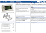
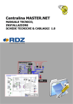
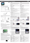
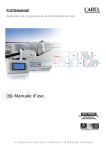
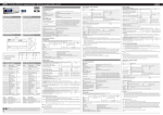
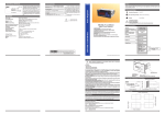
+050001840 - rel. 1.2 - 16.12.2013 pLDPRO PLD**GFP00 Interfaccia utente / User interface Dimensioni / Dimensions (mm) drilling template 71x29 mm Il display grafico pLDPRO è un dispositivo elettronico, compatibile con i precedenti terminali della linea PGD1, che consente la completa gestione della grafica tramite la visualizzazione di icone (definite a livello di sviluppo software applicativo) e la gestione di font internazionali di due dimensioni: 6x8 e 12x16 pixels e segnale acustico attivabile da buzzer. Il software applicativo è residente soltanto sulla scheda pCO, il terminale non ha bisogno di nessun software aggiuntivo in fase di utilizzo. Inoltre il terminale offre un ampio range di temperatura di funzionamento (-20T60 °C) e il frontale garantisce un elevato grado di protezione (IP65). The pLDPRO graphic display is an electronic device that is compatible with the previous PGD1 line terminals; it allows complete management of graphics by the display of icons (defined at application software development level), and the management of international fonts, in two sizes: 6x8 and 12x16 pixels, and acoustic signal through piezoelectric buzzer as well. The application software resides on the pCO controller and therefore the terminal does not require any additional software for operation. Furthermore, the terminals feature a wide operating temperature range (-20T60 °C) , the index of protection of front panel of IP65. Installazione pLDPRO pLDPRO Installation Questo terminale è stato progettato per il montaggio a pannello; la dima di foratura deve avere dimensioni di 71x29mm come indicato in Fig. 1. Per l’installazione seguire le istruzioni riportate di seguito: • Inserire il terminale nell’apertura, e fissare il dispositivo al pannello utilizzando due staffe di plastica scorrevoli laterali, come mostrato in Fig.2. • Infine, installare la cornice a scatto. This terminal has been designed for panel installation; the drilling template measures 71x29mm, as shown in Fig.1. For installation, proceed as follows: • Insert the terminal into the opening, and fasten the device to the panel using two lateral sliding plastic brackets, as shown in Fig.2. • Finally, fit the click-on frame Electrical connection Connessioni elettriche 34.6 mm • Collegare il cavo telefonico (cod. S90CONN00 *) dal controllo pCO al connettore (RJ11) posto sul retro del terminale. Come indicato in Fig.3 Configurazione indirizzo È possibile configurare l’indirizzo del terminale solo dopo aver fornito alimentazione allo stesso tramite il connettore telefonico RJ11 (il valore preimpostato in fabbrica è 32). Per entrare in modalità configurazione premere contemporaneamente i tasti 76 mm 34.4 mm 38.4 mm Fig. 1 Montaggio a pannello / Panel mounting terminal Fig. 2 Connessioni elettriche / Electrical connection pLAN Fig. 3 Smaltimento del prodotto: l’apparecchiatura (o il prodotto) deve essere oggetto di raccolta separata in conformità alle vigenti normative locali in materia di smaltimento. / Disposal of the product: the appliance (or the product) must be disposed of separately in accordance with the local waste disposal legislation in force. • pLAN: Connect the telephone cable (code S90CONN00*) from the pCO controller to the connector provided (RJ11) on the rear of the terminal. As shown in Fig.3 Configuring the address The address of the terminal can be configured only after having connected the power supply, using the RJ11 telephone jack (the factory default value is 32). +↓+↑e (sempre presenti in tutte le versioni) per almeno 5 secondi; verrà visualizzata la maschera di Fig. 4 con il cursore lampeggiante nell’angolo in alto a sinistra: • Per modificare l’indirizzo del terminale (display address setting) premere una volta il tasto : il cursore si sposterà sul campo indirizzo (nn). • Tramite i tasti ↓↑selezionare il valore voluto, e confermare ripremendo il tasto . Se il valore selezionato è diverso da quello memorizzato precedentemente apparirà la maschera di Fig. 5 e il nuovo valore verrà memorizzato nella memoria permanente del display. Se si imposta il campo nn al valore 0, il terminale comunicherà con la scheda pCO usando il protocollo “punto-punto” (non pLAN) e il campo “I/O Board address: xx” scompare in quanto privo di significato. +↓+↑buttons To access configuration mode, press the together and hold them for at least 5 seconds; the screen shown in Fig. 4 will be displayed, with the cursor flashing in the top left corner: • To change the address of the terminal (display address setting), press the button once, the cursor will move to the address field (nn). • Use the ↓↑ buttons to select the desired value, and confirm by pressing again. If the value selected is not the same as the one saved previously, the screen shown in Fig. 5 will be displayed, and the new value will be saved to the permanent memory. If the field nn is set to 0, the terminal will communicate with the pCO controller using “point-to-point” protocol (not pLAN) and the field “I/O Board address: xx” will not be displayed, as it has no meaning. pCO: assegnazione lista terminali privati e condivisi (per modalità pLAN) pCO: assigning the list of private and shared terminals (For pLAN mode) A questo punto, se fosse necessario modificare la lista dei terminali associata ad ogni singola scheda pCO, si dovrà seguire la seguente procedura: At this point, if the list of terminals associated with each individual pCO controller needs to be modified, proceed as follows: • entrare nella modalità configurazione con i tasti +↓+↑, come descritto nel paragrafo precedente; • premere il tasto fino a che il cursore si posiziona sul campo xx (I/O board address) Fig. 4; • tramite i tasti ↓↑scegliere l’indirizzo della scheda pCO desiderata. I valori selezionabili saranno solo quelli delle schede pCO effettivamente in linea. Se la rete pLAN non funziona correttamente, oppure non è presente nessuna scheda pCO, non sarà possibile modificare il campo che mostrerà solo “—”; • premendo ancora una volta il tasto verranno visualizzate in sequenza le maschere di Fig. 5; • anche qui il tasto muove il cursore da un campo all’altro e i tasti ↓↑ cambiano il valore del campo corrente. Il campo P:xx mostra l’indirizzo della scheda selezionata; nell’esempio di figura è stata selezionata la 12; • per uscire dalla procedura di configurazione e memorizzare i dati selezionare il campo “OK ?” impostare Yes e confermare con il tasto . I campi della colonna “Adr” rappresentano gli indirizzi dei terminali associati alla scheda pCO di indirizzo 12, mentre la colonna Priv/Shared indica il tipo di terminale. • access configuration mode using the +↓+↑ buttons, as described in the previous paragraph; • press the button until the cursor moves to the field xx (I/O board address) Fig.4; • use the ↓↑buttons to select the pCO controller in question. The values available correspond to the pCO controllers that are effectively on line. If the pLAN network is not working correctly, or if no pCO controller is present, the field cannot be modified, and the symbol “—” will be displayed; • pressing again displays the screens shown in Fig. 6, in sequence; • here too, the button moves the cursor from one field to the next, and the ↓↑ buttons change the value of the current field. The field P:xx shows the address of the controller selected; in the example shown in the figure, the value 12 has been selected; • to exit the configuration procedure and save the data, select the field “OK ?”, choose Yes and confirm by pressing . The fields in the “Adr” column represent the addresses of the terminals associated with the pCO controller that has address 12, while the Priv/Shared column indicates the type of terminal. Nota: i terminali della linea pLDPRO non possono essere configurati come “Sp” (shared printer) in quanto privi dell’uscita stampante. Se il terminale rimane inattivo (nessun tasto premuto) per più di 30 secondi esce automaticamente dalla procedura di configurazione senza memorizzare gli eventuali cambiamenti. Note: the pLDPRO terminals cannot be configured as “Sp” (shared printer), as they have no printer port. If the terminal remains inactive (no button is pressed) for more than 30 seconds, the configuration procedure is exited automatically, without saving any changes. Configurazione indirizzo / Configuring the address Fig.4 Segnalazione guasti Fault signals Se il terminale rivela lo stato di fuori linea della scheda pCO a cui è stato associato cancella il display e visualizza il messaggio: I/O Board xx fault. Mentre, se il terminale non riceve nessun segnale di rete, cancella il display e visualizza il seguente messaggio: NO LINK. If the terminal detects the off-line status of the pCO controller it is associated with, the display shows the message: I/O Board xx fault. On the other hand, if the terminal receives no signal from the network, the display shows the following message: NO LINK. Visualizzazione stato rete e versione del firmware Displaying status of network and firmware release Premendo contemporaneamente i tasti di configurazione ( +↓+↑) per almeno 10 secondi, si visualizza la maschera di Fig. 7. La schermata in Fig. 7 esemplifica lo stato della rete pLAN, visualizzando quanti e quali dispositivi sono collegati, e con quale indirizzo. : controllore pCO attivo in rete Fig.5 Assegnazione lista terminali privati e condivisi / Assigning the list of private and shared terminals :terminale attivo in rete : terminals active in network :nessun dispositivo collegato The example in Fig. 7 represents: pCO controllers active in network, addresses: 1, 2, 25 terminals active in network, addresses: 3, 4, 15, 26. To exit the NetSTAT procedure, press . Regolazione contrasto e versione firmware Contrast adjustment and firmware version + ! + per egolare il contrasto. • Per controllare la versione firmware, premere il pulsante e tenerlo premuto fino a che viene visualizzata la schermata mostrata in Fig. 8. Per reimpostare il contrasto su default, premere il tasto come indicato in figura Fig.8. Specifiche tecniche Display Tipo Retroilluminazione Risoluzione grafica Modi testo: Altezza carattere: Fig. 7 Regolazione contrasto e versione Firmware / Contrast adjustment & firmware version 4FUQ-%130EFGBVMU 1BSBNFUFST 1SFTTFOUFSUPDPOGJSN Q-%1307 .BS Fig. 8 NO POWER & SIGNAL CABLES TOGETHER WARNING: separate as much as possible the probe and digital input signal cables from the cables carrying inductive loads and power cables to avoid possible electromagnetic disturbance. Never run power cables (including the electrical panel wiring) and signal cables in the same conduits. READ CAREFULLY IN THE TEXT! IMPORTANT WARNINGS: the CAREL product is a state-of-the-art product, whose operation is specified in the technical documentation supplied with the product or can be downloaded, even prior to purchase, from the website www.carel.com. - The client (builder, developer or installer of the final equipment) assumes every responsibility and risk relating to the phase of configuration the product in order to reach the expected results in relation to the specific final installation and/or equipment. The lack of such phase of study, which is requested/indicated in the user manual, can cause the final product to malfunction of which CAREL can not be held responsible. The final client must use the product only in the manner described in the documentation related to the product itself. The liability of CAREL in relation to its own product is regulated by CAREL’s general contract conditions edited on the website www.carel.com and/or by specific agreements with clients. : no device connected Es. la Fig. 7 rappresenta: controllori pCO attivi in rete con indirizzo: 1, 2, 25 terminali attivi in rete con indirizzo: 3, 4, 15, 26. Per uscire dalla procedura NetSTAT premere il tasto . • Premere i tasti Fig.6 Pressing the configuration buttons ( +↓+↑ ) together for at least 10 seconds , displays the screen shown in Fig. 7. The screen shown in Fig. 7 provides an example of the status of the pLAN, displaying which and how many devices are connected, and the corresponding addresses. : pCO controllers active in network Dimensione area attiva: Dimensione area visiva: Alimentazione tensione • Use + ! + buttons to adjust the contrast. • To check firmware version, press button and hold it, then supply power until the screen shown in Fig.8 is displayed. • To set the contrast to default, press when displaying the screen shown in Fig.8. Technical specification grafico FSTN LED bianco 132x64 pixels 8 righe x 22 colonne (font 6x8pixels) 4 righe x 11 colonne (font 12x16 pixels) oppure modi misti 2 mm (font 6x8pixels) 4 mm (font 12x16 pixels) 36.94*15.98mm Display Type Backlighting Graphic resolution 38.9*19.4mm Size of active area: Size of display area: Power supply porta pLAN: alimentazione da pCO tramite connettore telefonico (18…30Vdc solo classe II); Potenza assor. max 0.5 W Distanze massime Lunghezza max 500 m con cavo AWG22 a coppie schermate rete pLAN: Distanza pCO 50 m con cavo telefonico terminale: 500 m con cavo AWG22 a coppie schermate e TCONN6J000. Nota: per raggiungere la lunghezza max utilizzare una tipologia a bus con diramazioni che non superano i 5 m. Nota: collegare solo circuiti di classe 2 al pLDPRO e utilizzare cavi con conduttori approvati per la temperatura di 75°C. Materiali Frontale trasparente policarbonato trasparente Retrocontenitori policarbonato +ABS grigio antracite Tastiera policarbonato Autoestinguenza: V0 per retrocontenitore V2 per frontale trasparente HB su tastiera siliconica e particolari restanti Generali Indice di protez. IP65 Condizioni di -20T60 °C, 90% r.H. non-condensante funzionamento Condizioni di -20T70 °C, 90% r.H. non-condensante immagazzin. Classe e struttura A del software Classificazione Da incorporare in apparecchiature di classe I protezione contro o II le scosse elettriche PTI dei materiali di 175 isolamento Periodo delle long sollecitaz. elettriche Categoria di resist. categoria D e B al calore e al fuoco Immunità contro categoria II le sovratensioni Inquinamento 2 ambientale: CAREL si riserva la possibilità di apportare modifiche o cambiamenti ai propri prodotti senza alcun preavviso. CAREL Industries HQs Via dell’Industria, 11 - 35020 Brugine - Padova (Italy) Tel. (+39) 0499716611 – Fax (+39) 0499716600 – www.carel.com – e-mail: [email protected] Text mode: Character height Voltage: Max. power input: Maximum distances Max. pLAN length: FSTN graphic white LED 132x64 pixels 8 rows x 22 columns (font sizes 6x8pixels) 4 rows x 11 columns (font size 12x16 pixels) or mixed modes 2 mm (font sizes 6x8pixels) 4 mm (font size 12x16 pixels) 36.94*15.98mm 38.9*19.4mm pLAN Port: power supply from pCO through telephone cable(18…30Vdc Class II only); 0.5 W 500 m with AWG22 twisted pair cable 50m with telephone cable 500m with AWG22 twisted pair cable and pCO terminal distance: TCONN6J000 Note: to reach the max. length,use a bus layout, with branches not exceeding 5m Note: only connetc class 2 circuits to the pLDPRO and wires must be approved for 75°C temperature. Materials Transparent front panel transparent polycarbonate Charcoal grey container polycarbonate +ABS back piece: Film keypad: polycarbonate film V0 for back piece Self-extinguishing V2 for transparent front panel classification: HB for film keypad and remaining parts Others Index of protection IP65 Operating conditions -20T60 °C, 90% r.H. non-condensing Storage conditions -20T70 °C, 90% r.H. non-condensing Software class and A structure: Classification according To be integrated into class 1 or 2 to protection against devices electric shock: PTI of insulating 175 materials: Period of electric stress long across insulating parts: Category of resistance category D and category B to fire and heat: Immunity against Category II voltage surges: Environmental 2 pollution: CAREL reserves the right to modify the features of its products without prior notice. +050001840 - rel. 1.2 - 16.12.2013