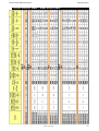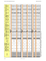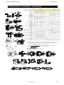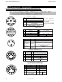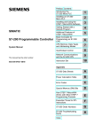
1
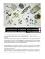
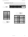
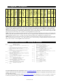
MotoriMotori-Motors
SMBSMB-MB
Manuale utente
User’s manual
rev. 1.6
1.6
Giugno 12
June
Ju
ne 12
Nota: Motori SMB con certificazione UL (secondo direttiva CSA) sono da richiedere esplicitamente al
momento dell’ordine. – Note: SMB Motors with UL certifications (according to CSA standards) shall
be expressly requested in the order.
1
2
9
1a
4
3a
8b
3
6
5
8a
10
7
11
14
15
12
16
13
1
1a
2
3
3a
4
Carcassa SMB – base casing SMB
Flangia SMB - flange SMB
Carcassa MB – base casing MB
Albero con magneti – shaft with magnets
Cuscinetto – bearing
Chiavetta – keyway
5
6
7
8a
8b
9
Flangia MB – flange MB
Statore – stator
Freno – brake
Resolver
Encoder
Supporto FBK – FBK cap
10
11
12
13
14
15
16
Scatola morsettiera – terminal box
Connettore MIL – MIL connector
Conn. Interconnectron
Conn. FastonMolex
Connettore MIL – MIL connector
Conn. Interconnectron
Conn. FastonMolex
Motore
Motor
Cavo
Cable
Le serie di motori brushless: MB a tecnologia tradizionale e SMB a poli salienti
Le serie di servomotori brushless MB ed SMB ad elevate prestazioni è stata concepita da Parker Hannifin per unire la
tradizionale affidabilità dei prodotti Parker con le alte prestazioni tipiche dei più avanzati servocomandi.
Le serie MB e SMB coprono coppie da 0,2 a 90Nm e velocità fino a 10000 rpm.
La vastità delle opzioni possibili permette al cliente di configurare il motore per renderlo il più adeguato al tipo di
applicazione.
Grazie all’ampio sovradimensionamento della meccanica, alla bassa inerzia inserita in una meccanica ad alta resistenza
ed all’ampiezza della gamma, la serie di motori brushless MB ed SMB consente l'utilizzo in applicazioni di ogni settore
ove l’alta dinamica e la massima affidabilità siano fondamentali.
Un fattore essenziale per l’utilizzo dei motori serie MB ed SMB è l’elevata qualità ed energia dei magneti al NeodimioFerro-Boro impiegati, che permettono di sopportare sovraccarichi elevati senza rischi di smagnetizzazione, grazie anche
alla metodologia di incapsulamento utilizzata per fissarli all’albero motore.
Brushless motor series: MB with standard technology and SMB with salient pole technology
The MB and SMB series of high-performance brushless servo motors have been designed to combine the traditional
reliability of Parker Hannifin products with the high-performance levels associated with cutting-edge servo controls.
The MB and SMB series cater for torques in the range of 0.2 to 90Nm, and speeds up to 10000 rpm.
Thanks to this broad range of available options, customers can configure an MB or SMB motor to exactly meet the
needs of different application types.
Adequate mechanical over-sizing, low inertia in an extra-strong mechanism and a broad range of models permits the
application of the MB series in all fields where high dynamic performance and utmost reliability are crucial features.
Thanks to the high quality and performance of the Neodymium-Iron-Boron magnets, and also the encapsulation method
used to fasten them to the shaft, the MB series of motors can achieve very high accelerations and withstand high
overloads without risk of demagnetisation or detachment of the magnets.
Parker Hannifin Manufacturing Srl
Motori Brushless
INDICE
1. Istruzioni di sicurezza e raccomandazioni – Safety instruction and recommendations .................................................. 7
2. Configurazione drive – Drive configuration................................................................................................................... 7
3. Caratteristiche generali – General characteristics .......................................................................................................... 8
4. Installazione – Installation.............................................................................................................................................. 9
5. Identificazione – Identification ....................................................................................................................................... 9
5.1.
Codice d’ordine – Order code ..................................................................................................................... 9
6. Dati motore MB56 – MB56 motor data ........................................................................................................................ 10
7. Dati motore MB70 – MB70 motor data ........................................................................................................................ 11
8. Dati motore MB105 – MB105 motor data .................................................................................................................... 12
9. Dati motore MB145 – MB145 motor data .................................................................................................................... 13
10. Dati motore MB205 – MB205 motor data .................................................................................................................. 15
11. Dati motore MB265 – MB265 motor data .................................................................................................................. 16
12. Dati motore SMB – SMB motor data ......................................................................................................................... 17
13. Disposizioni e connettori – Connectors ...................................................................................................................... 19
14. Connessioni – Connections ......................................................................................................................................... 20
14.1.
Connettori MIL per MB(A)–SMB(A) [tranne MB(A)56] – MIL connectors for MB(A)–SMB(A) [except
MB(A)56] .................................................................................................................................................................. 20
14.2.
Connettore MIL per MB(A)56 – MIL connector for MB(A)56 ............................................................... 21
14.3.
Connessioni INTERCONNECTRON per MB(A)–SMB(A) INTERCONNECTRON connections for
MB(A)-SMB(A) ........................................................................................................................................................... 21
14.4.
Connettore FASTON/MOLEX per SMB42, SMB60 – FASTON/MOLEX connector for SMB42,
SMB60
.................................................................................................................................................................. 22
14.5.
Scatola morsettiera per MB(A)56 – SMB(A)60 – Terminal box for MB(A)56 – SMB(A)60.................. 23
14.6.
Scatola morsettiera per MB(A)70-105 - SMB(A)82-100-115 – Terminal box for MB(A)70-105 SMB(A)82-100-115 ...................................................................................................................................................... 24
14.7.
Scatola morsettiera per MB(A)145-205 SMB(A)142 – Terminal box for MB(A)145-205 SMB(A)142 . 24
14.8.
Morsettiera di potenza – Power terminal board ........................................................................................ 24
14.9.
Fili volanti – Flying cables ....................................................................................................................... 25
15. Dimensioni meccaniche – Mechanical dimensions .................................................................................................... 26
16. Variazione ingombri encoder – Variation of dimensions with encoder ...................................................................... 27
17. Specifiche opzioni – Option specifications................................................................................................................. 28
18. Pesi – Mass ................................................................................................................................................................. 29
19. Carichi radiali – Permissible loads ............................................................................................................................. 30
19.1.
Tabella dei massimi carichi radiali ammissibili – Table of Maximum radial loads permissible .............. 30
19.2.
Calcolo carico radiale – Calculus of radial load ....................................................................................... 31
20. Specifiche dispositivo retroazione – FBK device specifications ................................................................................. 31
21. Legenda – Inscription ................................................................................................................................................. 33
22. Storia delle revisioni – History of manual .................................................................................................................. 33
Cod 1107131700
6
M MO 16 06/12 IE
Parker Hannifin Manufacturing Srl
Motori Brushless
1.Istruzioni di sicurezza e raccomandazioni – Safety
instruction and recommendations
I motori brushless a magneti permanenti devono essere maneggiati da personale qualificato.
The permanent magnet brushless motors must be handled by professional personnel.
Non toccare i contatti elettrici di potenza quando il dispositivo è alimentato da
corrente elettrica. Pericolo di scosse elettriche.
Do not touch the power contacts when the device is energised. Electric shock
hazard. Danger of electrical shocks!
La carcassa del motore può essere molto calda. Non toccare. Pericolo di ustioni.
The motor casing could be very hot. Do not touch it. Burn hazard.
Non colpire il motore con il martello.
Do not hit the motor with the hammer.
Maneggiare il motore con cura. Utilizzare i guanti adeguati per proteggere le mani,
ed evitare di sollevare a mano i motori pesanti ma utilizzare gli appositi mezzi di
sollevamento. Un motore non maneggiato con cura può causare tagli e abrasioni.
Handle the motor carefully. Use proper gloves to protect your hands, and avoid
lifting heavy motors manually. Use proper lifting mechanisms. If the motor is not
handled carefully, it can cause cuts and abrasions.
Eseguire i collegamenti del dispositivo in maniera corretta. Un errato collegamento
non permette di avere il controllo del motore.
Make device connections properly. Wrong connections will prevent proper motor
control.
Montaggio: rispettare i carichi radiali ammessi; evitare le sollecitazioni radiali
dell’albero motore; fare in modo che l’aria circoli liberamente intorno al motore; in
fase di accoppiamento/disaccoppiamento evitare di danneggiare il motore; evitare
che materiali liquidi/corrosivi vadano a contatto con il motore. – Mounting: observe
the radial load; avoid the radial stress to the motor shaft; leave a free space to
ensure motor cooling; avoid to damage the motor during the coupling/de-coupling;
avoid the contact with liquid/corrosive solution.
2.Configurazione drive – Drive configuration
I dati motore devono essere inseriti nei drive Parker Hannifin, prodotti dalla divisione EME, nei
seguenti parametri:
The motor data shall be inserted in the Parker Hannifin drives, manufactured by EME division with
the following parameters:
Pr29: numero poli motore – number of motor poles
Pr30: offset resolver (solo per SMB42: – only for SMB42: Pr30=6560)
Pr32: velocità massima = ω [rpm] * 1.1 – maximum speed = ω [rpm] * 1.1
Pr33: corrente nominale I065 o In65 [Arms] – nominal current I065 o In65 [Arms]
Pr34: numero poli resolver (Pr60 per HiDrive) – number of resolver poles (Pr60 for HiDrive)
Pr46: resistenza motore fase-fase R [Ω] – motor resistance phase to phase R [Ω]
Pr47: induttanza motore fase-fase L [mH] – motor inductance phase to phase L [mH]
M MO 16 06/12 IE
7
Parker Hannifin Manufacturing Srl
Motori Brushless
3.Caratteristiche generali – General characteristics
STANDARD
Dati validi per altitudine inferiore a 1000 m
slm secondo EN 60034-1 e temperatura
operativa: -10°C ÷ + 40°C
Forza controelettromotrice sinusoidale
Poli motore: 4 (MB 56 e 70), 8 (MB
105÷265, SMB60÷142), 10 (SMB42)
Retroazione: resolver 2 poli
Magneti: NdFeB
Soglia di intervento del PTC: 130°C
Isolamento: cavi classe F
avvolgimenti classe H
Protezione: IP64, secondo EN 60034-5, EN
60529 e EN 60529/A1
Flangia: B5
Collegamenti: connettore MIL
Albero con linguetta
Equilibratura: mezza linguetta
Cuscinetti lubrificati a vita
Accessori standard inclusi: parte volante del
connettore di potenza e segnale
Certificazioni: CE
Run-Out dell'albero, concentricità tra albero
e centraggio, perpendicolarità tra albero e
flangia secondo la IEC 60072-1 classe
normale
STANDARD
Data valid for altitudes below 1000 m slm
according to EN 60034-1 and ambient
operating temperature:-10°C ÷ + 40°C
Sinusoidal back EMF
Motor poles: 4 (MB 56 and 70), 8 (MB
105÷265, SMB60÷142), 10 (SMB42)
Feedback: 2-poles resolver
Magnets: NdFeB
PTC operating threshold: 130°C
Insulation: cabling class F
winding class H
Protection: IP64, according to EN 60034-5,
EN 60529 and EN 60529/ A1
Flange: B5
Connections: MIL connector
Shaft with keyway
Balancing: with half key
Bearings lubricated for life
Standard accessories: mating half of power
and signal connectors
Certifications: CE
Shaft Run-Out, Concentricity of spigot and
shaft, Perpendicularity of mounting face of
flange to shaft as per IEC 60072-1 Normal
Class
OPZIONI
OPTIONS
Retroazione: encoder incrementale, SinCos, Feedback: incremental encoder, SinCos,
encoder assoluto monogiro e multigiro con absolute encoder singleturn and multiturn
with EnDat and Hiperface protocol
protocollo EnDat e Hiperface
Additional devices: preparation for fitting an
Dispositivi aggiuntivi: predisposizione
external encoder in addition to internal
montaggio encoder esterno in aggiunta al
resolver
resolver interno
Connections: Interconnectron connectors,
Collegamenti: connettore Interconnectron,
terminal board box, cable output with flying
scatola morsettiera, uscita cavi con
female connectors (position defined by
connettori volanti (posizione definibile
customer)
dall’utente)
Holding brake
Freno di stazionamento
Fan: auto/servo-ventilated
Ventilatore: auto e servo azionato
(MBV and MBSV)
(MBV e MBSV)
Flange: B14, B3
Flangia: B14, B3
Alberi senza linguetta, bisporgenti con foro Shafts without keyway, double-shaft and
custom specials
passante e speciali
Shaft seal oil retainer ring
Anello paraolio per tenuta albero
Protection: IP65
Protezione: IP65
Protection: ATEX according to EN 50014,
Sicurezza aumentata ATEX secondo EN
50014, EN 50019, e Direttiva 94/9/CE (MBX) EN 50019, and Directive 94/ 9/ CE (MBX)
Water cooled motors (MBW)
Motori raffreddati ad acqua (MBW)
Rotor inertia: configurable
Inerzia rotore: configurabile
Certifications: UL and cUL (SMB except 42)
Certificazioni: UL e cUL (SMB eccetto 42)
8
M MO 16 06/12 IE
Parker Hannifin Manufacturing Srl
Motori Brushless
4.Installazione – Installation
Posizione
I servo motori sono costruiti in modo tale da permettere qualsiasi posizione di montaggio, poichè sono provvisti di
cuscinetto bloccato nel lato di accoppiamento.
Position
The servo motors are built so as to cater for any fitting position because of featuring a locked bearing on the coupling
side.
Montaggio
Un buon accoppiamento assicura il corretto funzionamento del motore. È importante quindi evitare di dare colpi al
motore che potrebbero rovinare i cuscinetti e l’albero. L’accoppiamento deve avere un buon allineamento per evitare
che il sistema abbia forti vibrazioni, movimenti irregolari e eccessive sollecitazioni meccaniche. Se il motore deve
essere accoppiato ad organi meccanici in bagno d’olio, assicurarsi della presenza dell’anello para olio. Prima di
accopiare il motore al sistema, verificare che il carico radiale rispettti i valori indicati nella tabella.
Coupling
Good coupling ensures correct motor operation. It is important therefore not to hit the motor as this could damage the
bearings and the shaft. Coupling shall be well aligned to prevent any strong vibrations, irregular movements and
excessive mechanical stress on the system. If the motor has to be coupled to mechanical organs in oil bath, make sure
the oil retainer ring has been fitted. Before coupling the motor to the system, make sure the radial load conforms with
the values shown on the table.
5.Identificazione – Identification
Nota: I dati dei motori MB sono equivalenti a quelli dei motori ME, MBV e MBSV; ed i dati dei motori SMB sono
equivalenti a quelli dei motori SME.
Note: The MB motor data are equivalent to the ME, MBV and SMBV motor data; the SMB motor data are equivalent to
the SME motor data.
5.1.
Codice d’ordine – Order code
MOTORE – motor type
SICUREZZA AUMENTATA – increased safety
FRENO DI STAZIONAMENTO – holding brake
VENTILAZIONE – fan
TAGLIA MOTORE – motor size
VELOCITA’ NOMINALE – nominal speed (100rpm)
COPPIA DI STALLO – stall torque DT=65K (Nm)
FLANGIA – flange
MB X A V 56 10 02 4 9 S 1 3 64 A1 M
4
DIAMETRO ALBERO – shaft diameter (mm)
ALBERO SENZA CHIAVETTA – shaft without keyway
DISPOSIZIONE CONNETTORI – connector layout
FORMA – form
GRADO DI PROTEZIONE (IP) – protection class
RETROAZIONE – feedback
INERZIA AUMENTATA – increased inertia
TENSIONE DI ALIMENTAZIONE – supply voltage 2=230V; 4=400V
M MO 16 06/12 IE
9
Parker Hannifin Manufacturing Srl
Motori Brushless
6.Dati motore MB56 – MB56 motor data
10
M MO 16 06/12 IE
Parker Hannifin Manufacturing Srl
Motori Brushless
7.Dati motore MB70 – MB70 motor data
M MO 16 06/12 IE
11
Parker Hannifin Manufacturing Srl
Motori Brushless
8.Dati motore MB105 – MB105 motor data
12
M MO 16 06/12 IE
Parker Hannifin Manufacturing Srl
Motori Brushless
9.Dati motore MB145 – MB145 motor data
M MO 16 06/12 IE
13
Parker Hannifin Manufacturing Srl
14
Motori Brushless
M MO 16 06/12 IE
Parker Hannifin Manufacturing Srl
Motori Brushless
10.Dati motore MB205 – MB205 motor data
M MO 16 06/12 IE
15
Parker Hannifin Manufacturing Srl
Motori Brushless
11.Dati motore MB265 – MB265 motor data
16
M MO 16 06/12 IE
Parker Hannifin Manufacturing Srl
Motori Brushless
12.Dati motore SMB – SMB motor data
M MO 16 06/12 IE
17
Parker Hannifin Manufacturing Srl
18
Motori Brushless
M MO 16 06/12 IE
Parker Hannifin Manufacturing Srl
Motori Brushless
13.Disposizioni e connettori – Connectors
0V
2IA
2D
2ID
■ : disponibile per motori MB(A) ~ SMB(A) – Available for MB(A) ~ SMB(A) motors
► : non disponibile per motori MBA ~ SMBA – Unavailable for MBA ~ SMBA motors
W : motori raffreddati ad acqua – Water-cooled motors
2IG
* Vedere il codice di identificazione alla voce “DISPOSIZIONE CONNETTORI”
* See the identification code at the “connector layout” part
MIL: connettore Militare – Military connector
Morsettiera – Terminal box
3
3C
3C8
3I
3MC
M MO 16 06/12 IE
19
Parker Hannifin Manufaturing Srl
Motori Brushless
14.Connessioni – Connections
Per vedere nei dettagli il collegamento dei cavi, vedere i documenti presenti sul sito.
For more details about cable connections, see the documents available on the website
14.1. Connettori MIL per MB(A)–SMB(A) [tranne MB(A)56] – MIL
connectors for MB(A)–SMB(A) [except MB(A)56]
POTENZA – POWER
A
B
C
D
U
V
W
TERRA-GND
SCHERMO cavo
cable SHIELD
FRENO–BRAKE 0Vdc *
FRENO–BRAKE + 24Vdc *
E
F
G
* Freno polarizzato
solo per taglie 145, 205
e serie SMB.
* Polarised brake for
sizes 145, 205 and SMB
series.
RESOLVER
A
B
C
D
E
F
EXCT +
EXCT –
COS –
COS +
SIN –
SIN +
G
H
K
J
SCHERMO cavo
cable SHIELD
SCHERMO cavo
cable SHIELD
PTC
KTYPTC
KTY+
ELETTROVENTILAZIONE – ELECTRIC FAN
A
MB 105
0Vdc
MB 145
220Vac
B
24Vdc
220Vac
C
N.C.
TERRA
GND
A
B
C
D
E
F
G
A
B
C
D
E
F
G
20
MB 205
220Vac
Connettere esternamente un
condensatore da 1.5µF 400Vac al pin C
Connect outside 1.5µF 400Vac
capacitor to pin C
220Vac
ENCODER INCREMENTALE
INCREMENTAL ENCODER
A
H
HALL A
AJ
HALL B
B
K
5V
BL
0V
Z
M
PTC
KTY+
SCHERMO cavo
ZN
cable SHIELD
HALL C
R
PTC
KTYENCODER SINCOS+HIPERFACE
SINCOS+HIPERFACE ENCODER
COS+
H
N.C.
COSJ
N.C.
SIN+
K
+Vdc
SINL
0V
RS485+
M PTC KTY+
RS485N
N.C.
SCHERMO cavo
R
PTC
KTYcable SHIELD
M MO 16 06/12 IE
Parker Hannifin Manufaturing Srl
Motori Brushless
14.2. Connettore MIL per MB(A)56 – MIL connector for MB(A)56
POTENZA - POWER
A
B
C
D
E
F
G
U
V
W
TERRA – SCHERMO cavo
GND – cable SHIELD
PTC
PTC
N.C.
RESOLVER
A
B
C
D
E
F
EXCT +
EXCT –
COS –
COS +
SIN –
SIN +
SCHERMO cavo
cable SHIELD
SCHERMO cavo
H
cable SHIELD
K
N.C.
J
N.C.
G
FRENO - BRAKE
A
FRENO-BRAKE
B
FRENO-BRAKE
C
N.C.
Il freno deve essere alimentato a 24Vdc e non è
polarizzato.
The brake shall be supplied at 24Vdc with no polarization.
14.3. Connessioni INTERCONNECTRON per MB(A)–SMB(A)
INTERCONNECTRON connections for MB(A)-SMB(A)
1
2
3
4
5
6
U
V
W
+
–
POTENZA - POWER
SMB(A)-MB(A)56,70,105,145
U
V
TERRA-GND
FRENO-BRAKE + 24Vdc
FRENO-BRAKE 0Vdc
W
POTENZA - POWER
MB(A) 205
U
V
W
FRENO–BRAKE + 24Vdc
FRENO-BRAKE 0Vdc
TERRA-GND
Nota: collegare lo
schermo del cavo alla
carcassa del connettore.
Note: connect the
cable shield to the
connector casing.
Nota: collegare lo
schermo del cavo alla
carcassa del connettore.
Note: connect the
cable shield to the
connector casing.
RESOLVER
1
2
3
4
5
6
SIN –
SIN +
N.C.
SCHERMO cavo
cable SHIELD
N.C.
N.C.
M MO 16 06/12 IE
7
8
9
10
11
12
EXCT –
PTC
KTYPTC
KTY+
EXCT +
COS +
COS –
Nota: collegare lo
schermo del resolver
alla carcassa del
connettore.
Note: connect the
resolver shield to the
connector casing.
21
Parker Hannifin Manufaturing Srl
Motori Brushless
1
2
3
4
5
6
1
2
3
4
5
6
5V
0V
A+
AB+
B-
ENCODER INCREMENTALE
INCREMENTAL ENCODER
7
Z+
13
HALL B+
8 PTC KTY- 14
HALL B9 PTC KTY+ 15
HALL C+
10
Z16
HALL C11
HALL A+
17
N.C.
12
HALL A-
Nota: collegare lo
schermo dell’encoder
alla carcassa del
connettore.
Note: connect the
encoder shield to the
connector casing.
ENCODER ASSOLUTO (SINCOS+ENDAT)
ABSOLUTE ENCODER (SINCOS+ENDAT)
UP SENSOR 7
UP
13
B–
N.C.
8
Clock +
14 DATA +
N.C.
9
Clock –
15
A+
0 V SENSOR 10
0V
16
A–
SCHERMO interno cavo
17 DATA –
PTC KTY- 11
cable inner SHIELD
PTC KTY+ 12
B+
ENCODER ASSOLUTO (SINCOS+HIPERFACE)
ABSOLUTE ENCODER (SINCOS+HIPERFACE)
TERRA (0V)
1
SIN +
7
13 RS485 GND (0V)
2
SIN 8 PTC KTY- 14
N.C.
3
RS485 +
9 PTC KTY+ 15
N.C.
4
N.C.
10
+ Vdc
16
N.C.
5
N.C.
11
COS +
17
N.C.
6
N.C.
12
COS -
Nota: collegare
lo schermo
dell’encoder alla
carcassa del
connettore.
Note: connect the
encoder shield to
the connector
casing.
Nota: collegare lo
schermo dell’encoder
alla carcassa del
connettore.
Note: connect the
encoder shield to the
connector casing.
14.4. Connettore FASTON/MOLEX per SMB42, SMB60 –
FASTON/MOLEX connector for SMB42, SMB60
1
2
3
4
5
6
1
2
3
4
5
6
1
2
3
4
5
6
22
POTENZA - POWER
TERRA – SCHERMO cavo
GND – cable SHIELD
FRENO – BRAKE 0Vdc
FRENO – BRAKE +24Vdc
W
V
U
RESOLVER
N.C.
7
N.C.
8
N.C.
9
PTC
10
PTC
11
12
TERRA – SCHERMO cavo
GND – cable SHIELD
SIN +
SIN –
COS +
COS –
EXTC –
EXTC +
ENCODER ASSOLUTO – ABSOLUTE ENC. (SINCOS+ENDAT)
UP SENSE
7
A+
0V SENSE
8
A–
UP
9
B+
0V
10
B–
CK +
11
DATA +
CK –
12
DATA –
M MO 16 06/12 IE
Parker Hannifin Manufaturing Srl
Motori Brushless
ENCODER ASSOLUTO – ABSOLUTE ENC. (SINCOS+ HIPERFACE)
1
SIN +
7
+Vdc
2
SIN –
8
COS +
3
RS485 +
9
COS –
4
0V
10
RS485 –
TERRA – SCHERMO cavo
5
PTC
11
GND – cable SHIELD
6
PTC
12
N.C.
14.5. Scatola morsettiera per MB(A)56 – SMB(A)60 – Terminal box for
MB(A)56 – SMB(A)60
POTENZA - POWER
A
B
C
U
V
W
TERRA-GND
RESOLVER
1
2
3
4
5
EXCT +
EXCT –
COS –
COS +
SIN –
M MO 16 06/12 IE
6
7
8
9
10
SIN +
KTYPTC
KTY+
PTC
FRENO–BRAKE +24Vdc
FRENO–BRAKE 0Vdc
23
Parker Hannifin Manufaturing Srl
Motori Brushless
14.6. Scatola morsettiera per MB(A)70-105 - SMB(A)82-100-115 – Terminal
box for MB(A)70-105 - SMB(A)82-100-115
POTENZA - POWER
A
B
C
D
U
V
W
TERRA-GND
RESOLVER
1 EXCT + 6
2 EXCT – 7
3 COS –
8
4 COS +
9
5 SIN – 10
SIN +
PTC
KTYPTC
KTY+
FRENO–BRAKE +24Vdc
FRENO–BRAKE 0Vdc
14.7. Scatola morsettiera per MB(A)145-205 SMB(A)142 – Terminal box for
MB(A)145-205 SMB(A)142
A
B
C
D
POTENZA - POWER
U
V
W
TERRA-GND
14.8. Morsettiera di potenza – Power terminal board
POTENZA - POWER
A
B
C
F
G
24
M MO 16 06/12 IE
U
V
W
FRENO–BRAKE 0Vdc
FRENO–BRAKE +24Vdc
TERRA-GND
Parker Hannifin Manufaturing Srl
Motori Brushless
14.9. Fili volanti – Flying cables
U
Bianco – white
Bianco – white
Bianco – white
RESOLVER
Bianco/rosso
EXCT +
White/red
Bianco/giallo
EXCT –
White/yellow
Giallo – Yellow COS +
Blu – Blue
COS Rosso – Red
SIN +
Nero – Black
SIN Blu – Blue
PTC
Blu – Blue
PTC
Giallo/verde
GND
Yellow/Green
POTENZA - POWER
V
W
Verde – green
Blu – blue
Rosso – red
Nero – black
Rosso – red
Verde – green
TERRA – GND
Giallo/verde
Yellow/Green
ENCODER
Rosso
Dc
Red
+5V
Nero – Black GND
Blu
A
Blue
Blu/nero
ABlue/black
Verde
B
Green
Verde/Nero
BGreen/Black
Giallo
Z
Yellow
M MO 16 06/12 IE
Giallo/nero
Yellow/black
Marrone – Brown
Marrone/nero
Brown/black
ZU
U-
Grigio – Grey
V
Grigio/nero
Grey/black
V-
Bianco – White
W
Bianco/nero
White/black
W-
25
Parker Hannifin Manufaturing Srl
Motori Brushless
15.Dimensioni meccaniche – Mechanical dimensions
265
205
145
MB
105
70
56
Motore - Taglia
Motor - Size
0,2
0,4
0,6
0,5
01
1,5
02
2,5
02
04
06
08
04
08
15
22
28
15
28
50
70
90
75
150
220
285
42
0,35
SMB
60
1,4
LM
130.5
150.5
170.5
158
188
218
248
278
186
229
273
317
200
231
292
354
416
239
273
342
411
480
328
435
542
658
110
129,5
82
03
163,5
100
06
191,5
115
10
220
142
15
243
DxL
C
DF
QF
F
G
bxh
t1
VxZ
SF
PC
9x20
11x23
40
5,5
56
63
74
3x3
4x4
10,2
12,5
M4x10
6,5
2,5
11x23
14x30
60
6
70
75
90
4x4
5x5
12,5
16
M4x10
M4x12.5
8,5
2,5
19x40
24x50
95
9.5
105
115
140
6x6
8x7
21,5
27
M6x16
M8x19
10
3,5
19x40
24x50
28x60
130
11,5
145
165
200
6x6
8x7
21,5
27
31
M6x16
M8x19
M10x22
12
3,5
38x80
42x110
180
14
205
215
250
10x8
12x8
41
45
M12x32
M16x40
18
4
48x114
250
19
266
300
342
14x9
51,5
M20x40
35
4
9x25
9x20
11x23
14x30
19x40
19x40
24x50
19x40
24x50
28x60
19x40
24x50
28x60
30
40
60
80
95
3,2
5,5
6
6,5
9
42,5
60
70
82
100
50
63
75
100
115
57,5
74
90
112
135
6
2,5
M4x10
7
2,5
10
3,5
9
100
115
135
10
3,5
95
110
130
9
9
11
115
130
145
130
130
165
156
156
196,5
10
3,5
130
11
142
165
192,5
10,2
10,2
12,5
16
21,5
21,5
27
21,5
27
31
21,5
27
31
M3x9
95
3x3
3x3
4x4
5x5
6x6
6x6
8x7
6x6
8x7
8x7
6x6
8x7
8x7
12
3,5
LM: lunghezza motore con resolver – motor body length with
resolver feedback
DxL: diametro per lunghezza albero – shaft diameter and length
C: centraggio – centring
DF: diametro fori fissaggio – retention hole diameter
QF: quadro flangia – flange board
F: interasse fori di fissaggio – retention hole centre distance
26
M5x12.5
M6x16
M6x16
M8x19
M6x16
M8x19
M10x22
M6x16
M8x19
M10x22
G: dimensione in diagonale – diagonal dimension
bxh: dimensione linguetta – key dimension
t1: albero con sporgenza linguetta – shaft with key protrusion
VxZ: dimensione foro per profondità – hole dimension for depth
SF: spessore flangia – flange thickness
PC: profondità centraggio – centring depth
M MO 16 06/12 IE
Parker Hannifin Manufaturing Srl
Motori Brushless
16.Variazione ingombri encoder – Variation of dimensions
with encoder
Codice
Code
56
A1
A2
A3
A6
A7
B1
B2
B3
B5
B6
B8
B9
C1
C2
C3
C4
C6
C7
C8
C9
D2
D3
D4
D5
MB
Incremento lunghezza [mm]
Increment length [mm]
70
105
145
◙
◙
◙
◙
◙
◙
∆10
∆19
∆19
∆10
∆19
∆19
205
◙
◙
◙
∆19
∆19
◙
◙
∆19
∆19
◙
◙
∆19
∆19
∆19
∆19
∆19
∆19
◙
∆19
∆19
∆19
◙
◙
◙
◙
∆19
∆19
◙
◙
◙
∆19
∆19
∆19
∆19
∆19
∆19
∆19
∆19
∆19
∆19
∆10
∆10
SMB
Incremento lunghezza [mm]
Increment length [mm]
60
82
100
115
◙
◙
◙
◙
◙
◙
◙
◙
◙
∆30, □82
∆24
∆20
◙
∆30, □82
∆24
∆20
◙
∆10
◙
◙
◙
∆10
◙
∆30, □82
∆24
∆20
◙
∆30, □82
∆24
∆20
◙
∆10
∆30, □82
∆24
∆20
◙
∆30, □82
∆24
∆20
◙
∆10
◙
◙
◙
◙
◙
◙
∆10
◙
∆20
◙
∆10
◙
∆20
◙
∆30, □82
∆24
∆20
◙
∆30, □82
∆24
∆20
◙
∆10
∆10
∆30, □82
∆20
◙
∆30, □82
∆20
◙
◙ : Nessuna variazione – No increment
∆ : Variazione lunghezza motore – Increment motor length
□ : Variazione quadro (solo per: SMB60) – Increment frame (only
for: SMB60).
Connettori
Connectors
142
◙
◙
◙
◙
◙
◙
◙
◙
◙
◙
◙
◙
◙
◙
◙
◙
◙
◙
0,M,I,MM,MI
0,M,I,MM,MI
0,M,I,MM,MI
0,F,A,M,I,MM,MI
0,F,A,M,I,MM,MI
0,M,I,MM,MI
0,M,I,MM,MI
0,M,I,MM,MI
0,F,I,MI
0,F,I,MI
0,M,I,MM,MI
0,F,I,MI
0,F,I,MI
0,M,I,MM,MI
0,M,I,MM,MI
0,M,I,MM,MI
0,F,A,M,I,MM,MI
0,F,A,M,I,MM,MI
0,F,I,MI
0,F,I,MI
0,M,I,MM,MI
0,M,I,MM,MI
0,F,I,MI
0,F,I,MI
Connettori (ved. la tabella connettori): – Connectors (to refer to te
connectors table):
0 (No conn.), F (FastonMolex), M (MIL), I (Interc.), A (Amph.),
MM (Mors. – T.Box + MIL), MI (Mors. – T.Box + Interc.)
M MO 16 06/12 IE
27
Parker Hannifin Manufaturing Srl
Motori Brushless
17.Specifiche opzioni – Option specifications
Specifiche inerzia aumentata per motori MB(codice ordine MB…M e MB…ML)
MB motors increased inertia specifications (order code MB…M and MB…ML)
105
145
205
motori MB – MB motors
0,2 0,4 0,6 0,8 0,4 0,8 15 22 28 15 28 50 70 90
Inerzia aggiuntiva MB…M [10–3 kgm2]
Extra inertia MB…M [10–3 kgm2]
Lunghezza aggiuntiva MB…M [mm]
Extra length MB…M [mm]
Peso aggiuntivo MB…M [kg]
Extra weight MB…M [kg]
Inerzia aggiuntiva MB…ML [10–3 kgm2]
Extra inertia MB…ML [10–3 kgm2]
Lunghezza aggiuntiva MB…ML [mm]
Extra length MB…ML [mm]
Peso aggiuntivo MB…ML [kg]
Extra weight MB…ML [kg]
0,14
0,79
4,4
0
0
0
0,340
0,990
2,065
0,53
n.d.
1,77
n.d.
12,1
n.d.
64
n.d.
74
n.d.
99
n.d.
1,5
n.d. 3,3
3,6
n.d. 7,6
Specifiche inerzia aumentata per motori SMB (codice ordine SMB…M)
SMB motors increased inertia specifications (order code SMB…M)
motori SMB – SMB motors
60
82
100
Inerzia aggiuntiva SMB…M [10–3 kgm2]
Extra inertia SMB…M [10–3 kgm2]
Lunghezza aggiuntiva SMB…M [mm]
Extra length SMB…M [mm]
Peso aggiuntivo SMB…M [kg]
Extra weight SMB…M [kg]
11,9
n.d.
115
142
0,029
0,27
0,284
0,9
0,69
31,5
43
47
45
50
0,32
0,91
0,68
2,28
2,49
Specifiche freni per motori MB (codice ordine MBA)
MB motors brake specifications (order code MBA)
56
70
105
145
motori MB – MB motors
Tutti - all Tutti - all 2 4 6 8 4 8 15 22 28
205
265
Tutti - all
Tutti - all
Coppia frenante statica [Nm]
0,6
2
10
4 8 15 22 28 120
450
Static braking torque [Nm]
Corrente assorbita a 20°C [A]
0,32
0,53
1,10
1,80
1,2
1,7
Current absorption at 20°C [A]
Tempo di inserzione massimo [ms]
250
250
250
250
80
40
Max engagement time [ms]
Tempo di rilascio minimo [ms]
100
100
100
100
150
180
Min disengagement time [ms]
Gioco angolare [°]
0
0
0
0
0
0
Angular play [°]
–3
2
Inerzia aggiuntiva [10 kgm ]
0,017 0,029
0,063
0,195
0,535
0,2
Extra inertia [10–3 kgm2]
Lunghezza aggiuntiva [mm]
51
56
64
74
99
80
Extra length [mm]
Peso aggiuntivo [kg]
0,8
1,1
3,0
5,0
14,0
18
Extra weight [kg]
Il freno di stazionamento (tensione di alimentazione 24VDC ±10%) è incorporato nel motore lato opposto
all’accoppiamento e chiude per caduta di tensione. A causa delle perdite di potenza dovute al freno, i valori di coppia
devono essere ridotti del 5%. I freni di stazionamento devono essere usati a motore fermo e non per frenate dinamiche.
Per usi normali non richiedono manutenzione.
The fail-safe (supply voltage 24VDC ±10%) holding brake is incorporated in the motor at the opposite side of the front
flange and is applied when there is no voltage present. Because of the power loss caused by the brake, torque values
must be reduced by 5%. The holding brakes shall be used with the motor at a standstill and not for dynamic braking.
For normal uses, they are maintenance free brakes.
28
M MO 16 06/12 IE
Parker Hannifin Manufaturing Srl
Motori Brushless
Specifiche freni per motori SMB (codice ordine SMBA)
SMB motors brake specifications (order code SMBA)
motori SMB – SMB motors
60
Coppia frenante statica [Nm]
Static braking torque [Nm]
Corrente assorbita a 20°C [A]
Current absorption at 20°C [A]
Tempo di inserzione massimo [ms]
Max engagement time [ms]
Tempo di rilascio minimo [ms]
Min disengagement time [ms]
Gioco angolare [°]
Angular play [°]
Inerzia aggiuntiva [10–3 kgm2]
Extra inertia [10–3 kgm2]
Lunghezza aggiuntiva [mm]
Extra length [mm]
Peso aggiuntivo [kg]
Extra weight [kg]
82
100
115
142
2,2
3,2
11
11
22
0,34
0,5
0,67
0,67
0,75
14
19
20
20
12,5
28
29
29
29
62
0
0
0
0
0
0,0125
0,043
0,104
0,1
0,2
31,5
45,5
47
45
50
0,3
0,7
0,6
2
3
Specifiche servoventilatori per motori MB (codice ordine MBSV)
MB motors servo controlled fan specifications (order code MBSV)
motori MB – MB motors
105
145
205
265
Tensione di alimentazione ±10% [V]
24Vdc
230Vac monofase – 1 phase
Input voltage ±10% [V – 1phase ]
Corrente assorbita [A]
0,17
0,35
0,22
0,66
Required current [A]
Frequenza [Hz]
50
50
50
50/60
Frequency [Hz]
Velocità di rotazione [rpm]
3000
3000
3000
Rotation speed [rpm]
Lunghezza aggiuntiva [mm]
64
97
109
140
Extra length [mm]
Peso aggiuntivo [kg]
1,0
2,0
2,2
15
Extra weight [kg]
Per motori servoventilati (cod. motore MBSV), prevedere un incremento di coppia e corrente del 25% (ad eccezione dei
dati di coppia e corrente massima), 30% per MB265. Il motore 205 servoventilato viene equipaggiato con un
condensatore esterno per l’avviamento del servoventilatore. Per motori autoventilati (cod. ordine MBV), prevedere un
incremento di coppia e corrente proporzionale alla velocità. Per motori raffreddati ad acqua (cod. motore MBW),
prevedere un incremento di coppia e corrente del 100% circa (ad eccezione dei dati di coppia e corrente massima).
In the case of servo-ventilated motors (order Code MBSV), a 25% torque and current increase should be envisaged
(except for the maximum torque and current data), 30% for MB265. The servo-ventilated 205 motor is equipped with an
external condenser for starting the fan. In the case of self-ventilated motors (order Code MBV), consider a torque and
current increase proportional to the nominal speed. For water-cooled motors (order code MBW), consider a
performance increase of approx. 100% in the torque and current, except for the maximum torque and current data.
18.Pesi – Mass
motori – motors
MB56
MB70
MB105
MB145
MB205
MB265
Taglia – Size
0,2 0,4 0,6 0,5 1 1,5 2 2,5 2 4 6 8 4 8 15 22 28 15 28 50 70 90 75 150 220 285
Peso – Mass [kg] 0,7 1 1,3 2 2,8 3,5 4,3 5,1 5 7 9 11 8 12 18 23 28 20 29 44 59 74 49 78 106 135
motori – motors
Taglia – Size
Peso – Weight [kg]
SMB42
0,35
0,9
SMB60
1,4
1,5
SMB82
3
3,6
SMB100
6
4,7
SMB115
10
7,7
SMB142
15
13
N.B.: Motore con resolver – Motor with resolver
M MO 16 06/12 IE
29
Parker Hannifin Manufaturing Srl
Motori Brushless
19.Carichi radiali – Permissible loads
19.1. Tabella dei massimi carichi radiali ammissibili – Table of Maximum
radial loads permissible
MOTORE
MOTOR rpm
N
0,2
MB 56 0,4
0,6
0,5
1
MB 70 1,5
2
2,5
2
4
MB 105
6
8
4
8
MB 145 15
22
28
15
28
MB 205 50
70
90
Tutte
MB 265
All
SMB 42 0,35
SMB 60 1,4
SMB 82 3
SMB100 6
SMB 115 10
SMB 142 15
250
N
581
609
629
410
439
458
472
483
1437
1579
1672
1737
1962
2107
2294
2412
2492
4816
5219
5772
6135
6391
Fmax : Massimo carico radiale applicabile all’albero motore
Fmax : Maximum radial load on motor shaft
500 750 1000 1500 2000 2500 3000 4500 6000
N
N
N
N
N
N
N
N
N
461
403
366
320
290
270
254
222
201
483
422
384
335
304
283
266
232
211
500
436
396
346
315
292
275
240
218
326
285
259
226
205
190
179
157
142
348
304
276
241
219
204
192
167
152
363
318
288
252
229
213
200
175
159
375
327
297
260
236
219
206
180
164
383
335
304
266
241
224
211
184
167
1141 996
905
791
718
667
628
548
498
1253 1095 995
869
790
733
690
603
547
1327 1159 1053 920
836
776
730
638
580
1378 1204 1094 956
868
806
759
663
602
1557 1360 1236 1080 981
911
857
749
1673 1461 1328 1160 1054 978
920
804
1821 1590 1445 1262 1147 1065 1002 875
1914 1672 1519 1327 1206 1119 1053 920
1978 1728 1570 1371 1246 1157 1088 951
3822 3339 3034 2650 2408 2235 2103
4142 3618 3287 2872 2609 2422 2279
4581 4002 3636 3177 2886 2679 2521
4869 4254 3865 3376 3067 2848 2680
5072 4431 4026 3517 3195 2966 2791
-
ALBERO
SHAFT
7500 10000
DxL
N
N
[mm]
187
170
196
178
11x23
203
184
132
141
147
14x30
152
155
24x50
28x60
42x110
-
6646
5485 4817
4376
3695
3290
3098
2839
-
-
-
-
48x114
717
1397
1422
1909
2087
569
497
1109 969
1129 986
1515 1324
1656 1447
452
880
896
1203
1315
395
769
782
1051
1149
359
699
711
955
1043
333
649
660
886
969
313
610
621
834
912
274
533
543
728
796
150
249
484
493
662
724
236
460
468
-
210
-
9x20
11x23
19x40
24x50
28x60
28x60
I dati sono relativi al carico radiale ammissibile, riferiti ad una vita dei cuscinetti di 20.000 ore e capacità del carico
applicata al centro dell’albero. Il carico radiale massimo ammissibile dipende dalla durata del servizio. Il carico assiale
massimo non può eccedere il 10% del massimo carico radiale ammesso.
ATTENZIONE: evitare colpi assiali sull’albero durante l’applicazione e l’utilizzo del motore.
The data relates to the permissible radial load, considering a bearing life of 20.000 hours and load capacity applied to
the centre of shaft end. The maximum permissible radial load will determine the service life. The maximum axial load
cannot exceed 10% of the maximum permissible radial load.
IMPORTANT: avoid axial impacts to the shaft during motor installation and use.
30
M MO 16 06/12 IE
Parker Hannifin Manufaturing Srl
Motori Brushless
19.2. Calcolo carico radiale – Calculus of radial load
Il carico radiale applicato all’albero motore FA deve soddisfare la disequazione sotto riportata.
The radial load applied to the motor shaft FA shall satisfy the inequality shown below.
FA ≤ Fmax •
(BB + L / 2)
(BB + X)
dove – where
Fmax
FA
X
L
D
BB
= carico radiale massimo (vedi tabella) [N]
maximum radial load (see table) [N]
= carico applicazione [N]
application load [N]
= distanza punto applicazione carico FA da
piano flangia [mm]
distance of FA load application point
from flange surface [mm]
= lunghezza albero standard (vedi tabella) [mm]
standard shaft length (see table) [mm]
= diametro albero [mm]
shaft diameter [mm]
= distanza dalla mediana cuscinetto anteriore al piano flangia [mm]
distance from the front bearing centre line to the flange surface [mm]
BB [mm]: MB56=13, MB70=19, MB105=23,5, MB145=26, MB205=34,5, MB265=31.5
BB [mm]: SMB42=0, SMB60=18,5, SMB82-70=19,3, SMB82=22,3, SMB100=23,5, SMB115=26, SMB142=26
20.Specifiche dispositivo retroazione – FBK device
specifications
RESOLVER
Poli – Poles
Rapporto di trasformazione – Transformation ratio
Temperatura operativa – Operating temperature
2
0,5
-50 ÷ +150°C
ENCODER INCREMENTALE – INCREMENTAL ENCODER
Codice – Code
Risoluzione [C/T]
Resolution [C/T]
Poli – Poles
Motori
Motors
A1
A2
A3
B1
B2
2000
2048
4096
3000
6000
8
8
8
4
8
105,145
205
82,100
115,142
MB
105,145,205
56,70
SMB
82,100,115,142
-
Precisione
System accuracy
Tensione – Voltage
Tacca di zero
Reference mark
Velocità massima
Max. speed
±32”
±32”
±16”
B8
2048 3000
±11”
C2
C3
2048
1000
8
8
4
-
-
56,70
60
60
-
±32” ±22”
±32”
C4
5000 1000
8
8
105,145
205
82,100
115,142
±64”
D2
D3
5000
8
8
-
-
60
60
±13” ±64”
±13”
+5Vdc ±5%, 200mA
Si – Yes
6000 min-1
200kHz (fino a 200kHz
Frequenza di
up to 85°C)
(fino a
risposta
up to
100kHz (fino a
Frequency response up to 100°C)
85°C)
Temp. operativa
Operating temp.
Circuito di uscita
Output circuit
±22”
B3
-20°C ÷
+100°C
200kHz (fino a – up to 85°C)
100kHz (fino a – up to 100°C)
-20°C
÷ 85°C
-20°C ÷ +100°C
300kHz
(fino a
up to
85°C)
-20°C
÷ 85°C
Line driver differenziale 20mA – line driver differential mode 20mA
M MO 16 06/12 IE
31
Parker Hannifin Manufaturing Srl
Motori Brushless
ENCODER ASSOLUTI HIPERFACE – HIPERFACE ABSOLUT ENCODER
Codice - Code
DSL
C6 S3
C7 S4 A6 S1 A7 S2
S5
S6
DSL
Ottico – Optical
Monogiro Multigiro Monogiro Multigiro Monogiro Multigiro
Singleturn Multiturn Singleturn Multiturn Singleturn Multiturn
1Vpp
1Vpp
1Vpp
1Vpp
n.a.
128
1024
n.a.
±320”
±90”
±40”
Protocollo DSL
Protocollo Hiperface Hiperface protocol
DSL protocol
4096 (12bit)
32768 (15bit)
262144 (18bit)
4096
4096
4096
(12bit)
(12bit)
8Vdc
8Vdc
7 … 12Vdc
12000rpm 9000rpm
6000rpm
12000rpm 9000rpm
+5°C ÷ +110°C
-20°C ÷ +115°C -20°C ÷ +115°C
Si
Si
Si
Si
Si
Si
No
No
No
No
Yes
Yes
Yes
Yes
Yes
Yes
Tipologia – Type
Segnali incrementali – Incremental signals
Sinusoidi a giro – Line count
Precisione – System accurancy
Valore posizione assoluta – Absolute position values
Posizioni al giro – Positions per rev.
Numero di giri – Distinguishable rev.
Alimentazione – Power supply
Velocità massima – Maximum speed
Temperatura – Temperature
Certificazione sicurezza SIL2
Safety SIL2
ENCODER ASSOLUTI ENDAT – ENDAT ABSOLUT ENCODER
Codice - Code
Tipologia
Type
Segnali incrementali
Incremental signals
Sinusoidi a giro
Line count
Precisione
System accurancy
Tacca di zero
Reference mark
Frequenza di taglio
Cutoff frequency
Valore pos. assoluta
Absolute pos. values
Posizioni al giro
Positions per rev.
Numero di giri
Distinguishable rev.
Alimentazione
Power supply
Velocità massima
Maximum speed
Temperatura
Temperature
32
C1
B5
D4
D5
B6
C8
C9
B9
Ottico – Optical
Induttivo – Inductive
Monogiro Multigiro Monogiro Multigiro Monogiro Multigiro Monogiro Multigiro
Singleturn Multiturn Singleturn Multiturn Singleturn Multiturn Singleturn Multiturn
1Vpp
1Vpp
512
512
2048
32
±60”
±60”
±20”
±400”
-
-
-
-
≥ 200 kHz
≥ 100 kHz
200 kHz
≥ 6 kHz
-
4096
(12bit)
5Vdc
≤160mA ≤200mA
12000rpm
-40°C ÷ +115°C
Protocollo EnDat
EnDat protocol
Protocollo EnDat
EnDat protocol
8192 (13bit)
131072 (17bit)
4096
(12bit)
5Vdc
≤150mA ≤250mA
-
-
4096
(12bit)
5Vdc
≤150mA ≤250mA
-
4096
(12bit)
5Vdc
≤130mA
15000rpm 12000rpm 15000rpm 12000rpm 15000rpm 12000rpm
-30°C ÷ +115°C
M MO 16 06/12 IE
-20°C ÷ +115°C
Voltage rating
Vn [Vrms] ■
Induttanza
fase-fase
L [mH] ■
Tensione Nominale
Vn [Vrms] ■
Resistenza
fase-fase
R [Ω] ▲/■
Phase-phase
resistance
R [Ω] ▲/■
Phase-phase
inductance L [mH] ■
FCEM a 1000rpm
V1000 [Vrms] ▲/■
Corrente massima
di stallo S3 10%
Imax [Arms]
Max stall current at
S3 10% Imax [Arms]
FCEM at 1000rpm
V1000
[Vrms] ▲/■
Corrente di stallo
∆T=65K I065 [Arms]
Stall current
∆T=65K I065 [Arms]
Costante di coppia
Kt [Nm/Arms] ▲/■
Coppia alla
velocità Nominale
∆T=65K Tn65 [Nm]
●
Torque at nominal
speed ∆T=65K Tn65
[Nm]
●
Torque costant
Kt [Nm/Arms] ▲/■
Velocità nominale
ω [rpm]
Nominal speed
ω [rpm]
Costante di f.e.m.
Ke [Vs] ▲/■
Inerzia J [10-3kgm2]
Inertia J [10-3kgm2]
E.m.f. costant
Ke [Vs] ▲/■
Coppia massima
di stallo S3 10%
Tmax [Nm] ●
Max stall torque at
S3 10% Tmax [Nm] ●
Corrente alla
coppia nominale
∆T=65K In65
[Arms]
Coppia di stallo
∆T=105K T0105 [Nm]
●
Stall torque
∆T=105K T0105 [Nm]
●
Current at
nominal torque
∆T=65K In65 [Arms]
Coppia di stallo
∆T=65K T065 [Nm] ●
Stall torque
∆T=65K T065 [Nm] ●
Model
Modello
21.Legenda – Inscription
MB: ● Dati riferiti al motore sospeso in posizione orizzontale in aria, temperatura ambiente a 20°C ♦ Dati riferiti al
motore montato su flangia in alluminio in posizione orizzontale con spessore di 20mm mantenuta a 20°C, temperatura
ambiente a 20°C ▲ Dati misurati a 20°C. A “caldo” prevedere un declassamento del 5 % ■ Dato con tolleranza ±10%
MB: ● Data referred to motor suspended in horizontal position in free still air, 20°C ambient temperature. ♦ Data
referred to motor flanged to a 20mm thick aluminium base at 20°C in horizontal position, 20°C ambient temperature ▲
Data measured at 20°C. When "hot" consider 5% derating ■ Tolerance data ±10%
SMB: ● Dati riferiti con motore montato su flangia in acciaio in posizione orizzontale avente dim. 200*230*20 mm
(per 60, 82), dim. 200*270*20 mm (per 100, 115, 142). Le coppie di stallo sono riferite con motore in rotazione a
100rpm ▲ Dati misurati a 20°C. A “caldo” prevedere un declassamento del 5 % ■ Dato con tolleranza ±10%
SMB: ● Data referred to motor mounted on a steel flange in horizontal position with dim. 200*230*20 mm (for 60, 82),
dim. 200*270*20 mm (for 100,115, 142). Stall torques refer to motor turning at 100rpm ▲ Data measured at 20°C.
When "hot" consider 5% derating ■ Tolerance data ±10%
22.Storia delle revisioni – History of manual
Rev 0
Rev 0.1
•
•
•
•
•
•
Rev 0.2
•
•
Rev 0.3
Rev 0.4
•
•
Rev 0.5
•
•
Rev 0.6
Rev 0.7
•
•
•
Luglio 2004 – July 2004
Marzo 2005 – March 2005
Integrazione nota connettore MIL potenza – correzione Encoder incr. per
conn. MIL.
Connettore interconnectron per encoder assoluto con interfaccia Hiperface.
Tabella encoder Hiperface – tabella resolver corretta.
MIL power connector note revision – Incremental encoder for MIL conn.
corrected.
Interconnectron connector for absolute encoder with Hiperface interface.
Hiperface encoder char – resolver char corrected.
Aprile 2005 – April 2005
Inserito connettore MIL per encoder SinCos + Hiperface – Inserted connector
MIL for SinCos + Hiperface encoder
Aggiornamento codici ordine per disposizione connettori – Adjourned codes
or der for disposition connectors
Settembre 2005 – September 2005
Aggiornamento tabella encoder incrementali – Adjourned Incremental
encoder table
Ottobre 2006 – October 2006
Connettore ventilatore per MB205 – MB205 fan connector
Dicembre 2006 – Dicember 2006
Scatola morsettiera SMB60 – Terminal box SMB60
Coppia frenante statica SMB82 – Static braking torque SMB82
Aprile 2007 – April 2007
Connettore ventilatore per MB145 – MB145 fan connector
IEC 60072-1 classe normale – IEC 60072-1 Normal Class
Febbraio 2008 – February 2008
MB265
•
•
Rev 0.8
•
•
•
Rev 0.9
•
Rev 1.0
•
Rev 1.1
•
Rev 1.2
•
Rev 1.3
•
•
Rev 1.4
•
•
•
Rev 1.5
•
Rev 1.6
•
Dimensioni motore – Motor dimensions
Connessioni: fili volanti – Connections: flying cables
Marzo 2008 – March 2008
MB265 correzione dati – MB265 data correct
Specifiche freni – Brake specifications
Dichiarazione di conformità CE – CE Declaration of conformity
Giugno 2008 – June 2008
Connessioni: fili volanti – Connections: flying cables
Marzo 2009 – March 2009
Connessioni: MB265 non più speciale ma uguale alle nostre – Connections:
MB265, equal to our standard
Aprile 2009 – April 2009
MB265
Settembre 2009 – September 2009
3MA-3MC: no per MB
Dicembre 2009 – December 2009
Codice d’ordine – Order code
SMB42
Luglio 2010 – July 2010
KTY
Codice d’ordine – Order code
Disposizioni connettori – Connectors
Luglio 2011 – July 2011
Encoder hiperface type S, safety SIL2
GIugno 2012 – June 2012
Encoder hiperface DSL
Per altri modelli di motori fare riferimento al sito www.parker.com/eme Modifiche ai dati del manuale possono essere
eseguite a discrezione del costruttore senza preavviso. I dati riportati nel manuale corrispondono alle specifiche relative
alla data della revisione.
For other motor models log into website www.parker.com/eme The manufacturer reserves the right to change the
technical specification of any product without notice. All data shown in the manual is correct at the time of revision.
M MO16 06/12 IE