1
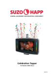
EVO90F
FRESNEL FIXTURE
Manuale Utente
User Manual
IT
EN
Music & Lights S.r.l. si riserva ogni diritto di elaborazione in qualsiasi forma delle presenti istruzioni per l’uso.
La riproduzione - anche parziale - per propri scopi commerciali è vietata.
Al fine di migliorare la qualità dei prodotti, la Music&Lights S.r.l. si riserva la facoltà di modificare, in
qualunque momento e senza preavviso, le specifiche menzionate nel presente manuale di istruzioni.
Tutte le revisioni e gli aggiornamenti sono disponibili nella sezione 'Manuali' sul sito www.musiclights.it
REV.001-04/13
EVO90F
INDICE
Sicurezza
Avvertenze generali
Attenzioni e precauzioni per l’installazione
Informazioni generali
4
4
5
1 Introduzione
1. 1 Descrizione
1. 2 Specifiche tecniche
1. 3 Elementi di comando e di collegamento
6
6
8
2 Installazione
2. 1 Montaggio
9
3 Funzioni e impostazioni
3. 1 Funzionamento
3. 2 Impostazione base
3. 3 Struttura menu
3. 4 Modalità dimmer
3. 5 Modalità setting
3. 6 Modalità Master/Slave
3. 7 Collegamento
3. 8 Configurazione canali DMX
3. 9 Indirizzamento DMX
3. 10 Collegamenti della linea DMX
3. 11 Costruzione del terminatore DMX
3. 12 Tabella canali DMX
10
10
11
12
12
13
13
14
14
15
15
16
4 Manutenzione
4. 1 Manutenzione e pulizia del sistema ottico
4. 2 Sostituzione fusibile
4. 3 Risoluzione dei problemi
17
17
18
5 Appendice
5. 1 Vista esplosa
19
Certificato di garanzia
Contenuto dell'imballo:
3
•
•
•
•
EVO90F
Staffa di fissaggio
Cavo di alimentazione
Manuale utente
EVO90F
4
ATTENZIONE! Prima di effettuare qualsiasi operazione con l’unità, leggere con attenzione
questo manuale e conservarlo accuratamente per riferimenti futuri. Contiene informazioni
importanti riguardo l’installazione, l’uso e la manutenzione dell’unità.
SICUREZZA
Avvertenze generali
• I prodotti a cui questo manuale si riferisce sono conformi alle Direttive della Comunità Europea e pertanto recano la sigla .
• Il dispositivo funziona con pericolosa tensione di rete 230V~. Non intervenire mai al suo interno al di
fuori delle operazioni descritte nel presente manuale; esiste il pericolo di una scarica elettrica.
• È obbligatorio effettuare il collegamento ad un impianto di alimentazione dotato di un’efficiente messa
a terra (apparecchio di Classe I secondo norma EN 60598-1). Si raccomanda, inoltre, di proteggere le
linee di alimentazione delle unità dai contatti indiretti e/o cortocircuiti verso massa tramite l’uso di
interruttori differenziali opportunamente dimensionati.
• Le operazioni di collegamento alla rete di distribuzione dell’energia elettrica devono essere effettuate
da un installatore elettrico qualificato. Verificare che frequenza e tensione della rete corrispondono alla
frequenza ed alla tensione per cui l’unità è predisposta, indicate sulla targhetta dei dati elettrici.
• L’unità non per uso domestico, solo per uso professionale.
• Evitare di utilizzare l’unità:
- in luoghi soggetti a vibrazioni, o a possibili urti;
- in luoghi a temperatura superiore ai 45°C o inferiori a -20°C.
• Evitare che nell’unità penetrino liquidi infiammabili, acqua o oggetti metallici.
• Non smontare e non apportare modifiche all’unità.
• Tutti gli interventi devono essere sempre e solo effettuati da personale tecnico qualificato. Rivolgersi al
più vicino centro di assistenza tecnica autorizzato.
• Se si desidera eliminare il dispositivo definitivamente, consegnarlo
per lo smaltimento ad un’istituzione locale per il riciclaggio.
Attenzioni e precauzioni per l’installazione
• Se il dispositivo dovesse trovarsi ad operare in condizioni differenti da quelle descritte nel presente
manuale, potrebbero verificarsi dei danni; in tal caso la garanzia verrebbe a decadere. Inoltre, ogni altra
operazione potrebbe provocare cortocircuiti, incendi, scosse elettriche, rotture etc.
• Prima di iniziare qualsiasi operazione di manutenzione o pulizia sull’unità togliere la tensione dalla rete
di alimentazione.
• È assolutamente necessario proteggere l’unità per mezzo di una fune di sicurezza. Nell’eseguire qualsiasi intervento attenersi scrupolosamente a tutte le normative (in materia di sicurezza) vigenti nel
paese di utilizzo.
• Installare l’unità in un luogo ben ventilato.
• Mantenere i materiali infiammabili ad una distanza di sicurezza dall’unità.
• I filtri, le lenti o gli schermi ultravioletti se danneggiati possono limitare la loro efficienza.
• I LED devono essere sostituiti se danneggiati o termicamente deformati.
• Non guardare direttamente il fascio luminoso. Tenete presente che i veloci cambi di luce possono provocare attacchi d’epilessia presso persone fotosensibili o epilettiche.
EVO90F
5
INFORMAZIONI GENERALI
Spedizioni e reclami
Le merci sono vendute “franco nostra sede” e viaggiano sempre a rischio e pericolo del distributore/cliente. Eventuali avarie e danni dovranno essere contestati al vettore. Ogni reclamo per imballi manomessi
dovrà essere inoltrato entro 8 giorni dal ricevimento della merce.
Garanzie e resi
Il prodotto è coperto da garanzia in base alle vigenti normative. Sul sito www.musiclights.it è possibile
consultare il testo integrale delle “Condizioni Generali di Garanzia”. Si prega, dopo l’acquisto, di procedere
alla registrazione del prodotto sul sito www.musiclights.it. In alternativa il prodotto può essere registrato
compilando e inviando il modulo riportato alla fine del manuale. A tutti gli effetti la validità della garanzia
è avallata unicamente dalla presentazione del certificato di garanzia. Music & Lights constata tramite verifica sui resi la difettosità dichiarata, correlata all’appropriato utilizzo, e l’effettiva validità della garanzia;
provvede quindi alla riparazione dei prodotti, declinando tuttavia ogni obbligo di risarcimento per danni
diretti o indiretti eventualmente derivanti dalla difettosità.
6
EVO90F
- 1 - INTRODUZIONE
1.1 DESCRIZIONE
EVO90F è un proiettore Fresnel con sorgente LED della gamma Prolights, ingegnerizzato per essere un’alternativa superiore in termini di performance e potenza ai fari convenzionali con lampada da 500W.
Disponibile nelle versioni Tungsten (3100K) e Daylight (5600K), EVO90F riproduce l’omogeneità di proiezione e la linearità del dimmer dei fari convenzionali, nonchè le stesse modalità di utilizzo, rendendolo un
proiettore user-friendly per lo staff-tecnico.
La versatilità è un fattore chiave per EVO90F, in particolare la capacità di Focus regolabile manualmente, in
grado di passare da un fascio Spot (10°) a Flood (60°) in base alle esigenze se occorre un pullback-shot o una
proiezione potente su un punto stretto. EVO90F offre la possibilità di modellare il fascio e tagliare il campo
della luce dispersa, grazie al set accessori di alette e bandiere.
EVO90F si comporta esattamente come un faro tradizionale, i risultati sono naturali ed il comportamento
delle ombre è il medesimo di un faro con sorgente singola. Il funzionamento è stato studiato per permettere
di rimpiazzare i Fresnel tradizionali con le versione LED senza modificare gli impianti pre-esistenti in studio.
La parte mancante rispetto gli illuminatori tradizionali risulta essere la produzione calore, EVO90F infatti offre
un funzionamento a freddo, riducendo i costi di condizionamento e rendendo l’ambiente più confortevole
sia per i tecnici dietro il set che per i talents.
1.2 SPECIFICHE TECNICHE
I vantaggi della tecnologia offerta da EVO90F:
• Risparmio energetico significativo in fase di funzionamento
• Risparmio nei cablaggi: collegamento in serie di alimentazione e dmx fino a 16 Fresnel
• Nessun bisogno di Dimmer e lampade, vita LED >50’000h
• Operazioni di manutenzione assenti, ideale per luoghi difficilmente accessibili
• Adatto per accensioni di lunga durata
• Minor spesa per impianti di aria condizionata
• Compatibile con accessori standard in commercio
• Accessori e ricambi virtualmente indistruttibili
• Temperatura colore costante sull’intera scala dimmer
• Flicker free in camera, adatto per studi televisivi
• Assenza di emissioni UV/IR
• Intallazione in sicurezza anche in prossimità del pubblico o di oggetti delicati (musei e teatro)
• Interfaccia display LED ed elettronica con diagnostica, calibrazione curva dimmer, setup DMX
Sorgente luminosa e ottica
• 9x10W (3A) LEDs-array
• Lumen: Tungsten 3090 lm, Daylight 3708 lm
• Lux (10°): Tungsten 6788 @2m , Daylight 8145 @2m
• Peak intensity: Tungsten 27000cd, Daylight 32400cd
• Color rendering: Tungsten >83Ra, Daylight >70Ra
• Temperatura colore: Tungsten 3100K, Daylight 5600K
• Angolo di proiezione: zoom 10°-60°
• Gruppo ottico ad alta efficienza per massimizzare uniformità di proiezione, precisione di focus, stabilità
temperatura colore sull'intera curva dimmer
• Durata media vita LED: >50'000 ore
EVO90F
7
Funzionamento ed elettronica
• Diverse configurazioni DMX disponibili (1, 2 canali)
-- 1 canale: dimmer
-- 2 canali: dimmer, dimmer fine
• Interfaccia di controllo mediante display LED 4 char
• Regolazione curva dimmer: 5 configurazioni selezionabili
• Frequenza dei diodi anti-flicker (>400Hz) adatta per ripresa in camera
• Silenziosità di funzionamento, ventilazione ad aria forzata con ventole silenziate
388
Corpo e alimentazione
• Corpo in alluminio ad alta resistenza progettato per facilitare la dissipazione termica
• Progettato per essere compatibile con accessori standard in commercio
• Ambiente: IP20
• Connessioni di alimentazione Input/Output: Neutrik NAC3MPA/NAC3MPB
• Connessioni di segnale Input/output: XLR3p/5p
• Staffa di sospensione, maniglie posteriori e leve di serraggio ideate per facilitare e velocizzare le fasi di
montaggio e puntamento
• Alimentazione: 100-240V 50/60Hz
• Condizioni di esercizio: -20/45°
• Output alimentazione per connessione di più unità in serie: fino a 16 proiettori a 230V
• Consumo ad emissione massima: 100W
• Peso: 5,5 kg
• Dimensioni (LxAxP): 325x281x266 mm
281
325
Fig.1
Diagramma di luminosità
Illuminance at a Distance
10°
Light Intensity Distribution (10°)
-90
2.0m
4.0m
6.0m
8.0m
10.0m
4516/6788lx
0.35m
1129/1697lx
0.70m
501/754x
1.05m
282/424lx
1.40m
180/271lx
Eavg/Emax
12000
-60
60
18000
24000
-30
1.75m
Beam Angle: 10°
90
6000
Beam Width
Average Beam Angle ( 50% ) : 10°
Fig.2
30000
0
30
— Vert. Intensity (cd)
— Hori. Intensity (cd)
EVO90F
8
1.3 ELEMENTI DI COMANDO E DI COLLEGAMENTO
1
2
3
PRESS
X2
MENU
UP
ENTER
DOWN
4
5
7
6
POWER IN
FUSE
POWER OUT
Fig.3
11
10
1. STAFFA DI MONTAGGIO
2. MANOPOLA DI FISSAGGIO per la staffa di
montaggio
3. CONTROLLO ROTATIVI
4. PANNELLO DI CONTROLLO con display e 4
pulsanti per accesso e gestione delle diverse
funzioni.
5. ALLOGGIAMENTO FUSIBILE in caso di rottura
del fusibile, sostituire sempre con uno dello
stesso tipo e dello stesso valore.
6. POWER IN (connettore di potenza Neutrik)
per il collegamento ad una presa di rete
(100-240V~/50-60Hz) tramite il cavo rete.
9
8
7. POWER OUT (connettore di potenza Neutrik):
output alimentazione per connessione di più
unità in serie (13 unità a 220V).
8. DMX OUT (XLR a 5 poli):
1 = massa, 2 = DMX -, 3 = DMX +, 4 N/C, 5 N/C;
9. DMX OUT (XLR 3 poli):
1 = massa, 2 = DMX -, 3 = DMX +
10. DMX IN (XLR a 5 poli):
1 = massa, 2 = DMX -, 3 = DMX +, 4 N/C, 5 N/C;
11. DMX IN (XLR 3 poli):
1 = massa, 2 = DMX -, 3 = DMX +
EVO90F
9
- 2 - INSTALLAZIONE
2.1 MONTAGGIO
Il proiettore EVO90F può essere collocato su un piano solido. Inoltre, grazie alle possibilità di fissaggio sulla
staffa (fig.2), l’unità può essere montata anche a testa in giù, su una traversa. Per il fissaggio occorrono dei
supporti robusti per il montaggio. L’area di collocazione deve avere una stabilità sufficiente e supportare
almeno 10 volte il peso dell’unità.
Inoltre assicurarsi di rispettare tutte le avvertenze in materia di sicurezza.
• Fissare il proiettore attraverso l’apposita staffa (1) ad una collocazione idonea.
• È assolutamente necessario assicurare il proiettore contro la caduta utilizzando un cavo di sicurezza: in
particolare collegare il cavo in un punto adatto in modo che la caduta del proiettore non possa superare i 20 cm.
• Orientare il proiettore intervenendo, se necessario, sulla manopola della staffa di montaggio (2).
1
2
Fig.4
EVO90F
10
- 3 - FUNZIONI E IMPOSTAZIONI
3.1 FUNZIONAMENTO
Per accendere l’EVO90F, inserire la spina del cavo di alimentazione in una presa di rete (100-240V 50/60Hz).
L’unità può essere comandata da un unità DMX di comando luce oppure svolgere autonomamente il suo
programma. Per spegnere l’EVO90F, staccare la spina dalla presa di rete. Per maggiore comodità è consigliabile collegare l’unità con una presa comandata da un interruttore.
3.2 IMPOSTAZIONE BASE
Il proiettore EVO90F dispone di un display LED e 4 pulsanti per accesso alle funzioni del pannello di controllo (fig.5).
MENU
UP
ENTER
DOWN
Fig.5
MENU
ENTER
Per scorrere il menu
principale o tornare ad
una opzione del menu
precedente
Per entrare nel menu
selezionato o confermare il
valore attuale della funzione o
l'opzione all'interno di un menu
UP
Per scorrere attraverso le
diverse funzioni in ordine
discendente o aumentare il
valore della funzione stessa
DOWN
Per scorrere attraverso le
diverse funzioni in ordine
ascendente o diminuire il
valore della funzione stessa
EVO90F
11
3.3 STRUTTURA MENU
MAIN FUNCTION
SELECTION
SUB-SELECTION
Dimmer
DIM
d.000 - d.100
DMX/Slave
RUN
DMX Address
ADDR
d001 - d512
CURV
SET
To select the operating mode of the fixture
SLAV
DIM
PERF
SLCK
DESCRIPTION
Manual control the intensity of the fixture
DMX
KEY
Special settings
SUB-SELECTION
DMX starting address selection
Off
On
Set the Key lock (password mode)
Off
Dimming curve off
Dim1
Dimming curve: dim1
Dim2
Dimming curve: dim2
Dim3
Dimming curve: dim3
Dim4
Dimming curve: dim4
Off
Adjust the shape of the Dimming curve: off
Cv1
Adjust the shape of the Dimming curve: 1
Cv2
Adjust the shape of the Dimming curve: 2
Cv3
Adjust the shape of the Dimming curve: 3
Live
Default mode which balances the requirements of
output and noise
Stdo
Mode low power and maintains extremely low noise
Powr
Mode at high power for long periods of time
Off
On
Setting access lock
Uno
PERS
Dos
Selects DMX Personality
Std.P
DERR
REST
MCON
Save
Continues with last command upon loss of DMX
control
Blak
Black out fixture upon loss of DMX
****
Reset fixture to factory defaults
Self
Not send DMX data to other fixture
Mast
Send DMX data to other fixture
EVO90F
12
3.4 MODALITÀ DIMMER
Questa modalità permette di regolare manualmente l’intensità del proiettore:
• Premere il tasto MENU fino a quando sul display non appare [DIM], quindi premere ENTER per confermare.
• Utilizzare i tasti UP/DOWN per selezionare il valore di intensità desiderato [d.000 - d.100].
• Premere il tasto ENTER per salvare l’impostazione.
3.5 MODALITÀ SETTING
Premere il tasto MENU e selezionare attraverso i tasti direzionali la voce [SET]; per confermare premere il
tasto ENTER.
É possibile accedere alle seguenti funzioni:
KEY
• Selezionando la funzione [KEY] è possibile attivare o disattivare la password di accesso.
• Selezionare [ON] o [OFF] a seconda che si voglia, rispettivamente, abilitare o disabilitare la password.
Quando l’unità è impostata su ON, dopo 30 secondi o al prossimo riavvio bisognerà immettere la
password di accesso.
NOTA - Le impostazioni di fabbrica relative alla password di accesso corrispondono alla combinazione dei tasti UP + DOWN + UP + DOWN. Premere ENTER per confermare.
DIMM
Selezionare la funzione [DIMM] per entrare nella modalità dimmer e scegliere e simulare diverse velocità dimming. In particolare, quando è impostato su [OFF] il dimmer è lineare. [DIM1/2/3/4] rappresentano
invece, i diversi valori di velocità nella modalità non lineare; [DIM1] è il valore più veloce mentre [DIM4]
il più lento.
CURV
Selezionare la funzione [CURV] per regolare la forma della curva dimmer; far riferimento al grafico riportato di seguito per la caratteristica di ciascuna curva.
CURV dimming
1: OFF
2: CV1
3: CV3
4: CV4
Fig.6
EVO90F
13
PERF
Selezionando la funzione [PERF] è possibile impostare le caratteristiche di prestazione del proiettore:
-- [LIVE] è la modalità predefinita del proiettore, e permette di bilanciare i requisiti di uscita e la rumorosità del dispositivo.
-- [STDO] è la modalità che consente di ridurre estremamente il rumore del proiettore in ogni momento
e di operare a un livello di potenza moderato.
-- [POWR] è la modalità che consente di operare ad alta potenza per lungo tempo aumentando la
rumorosità del proiettore.
SLCK
• Selezionando la funzione [SLCK] è possibile attivare o disattivare la password di accesso al menu di
impostazioni.
• Selezionare [ON] o [OFF] a seconda che si voglia, rispettivamente, abilitare o disabilitare la password.
Quando l’unità è impostata su ON, bisognerà immettere la password per accedere al menu impostazioni.
DERR
Selezionare la funzione [DERR], per la gestione in caso di errore del segnale DMX.
-- [SAVE] consente di salvare gli ultimi dati DMX in caso di errore del segnale DMX.
-- [BLACK] consente di attivare la modalità blackout in caso di errore DMX.
REST
Selezionare la funzione [REST] per ripristinare i valori di default. Per eseguire l’operazione è necessario
inserire la password.
MCON
Selezionando la funzione [MCON], è possibile caricare i dati DMX dall’unità corrente Master alle unità
Slave. Selezionare [MAST] o [SELF] a seconda che si voglia, rispettivamente, abilitare o disabilitare il trasfrimento dati DMX dall’unità Master alle unità Slave.
3.6 MODALITÀ MASTER/SLAVE
Questa modalità consente di collegare in linea più unità EVO90F senza un controller. La prima unità sarà
impostata come master e le altre funzioneranno come slave con lo stesso effetto.
• Premere il MENU fino a quando sul display non appare [RUN] quindi premere ENTER per confermare.
• Premere i tasti UP/DOWN e selezionare la modalità [SLAV].
• Servirsi dei connettori DMX del EVO90F e di un cavo XLR per formare una catena di unità. In certe condizioni e lunghezze si consiglia di effettuare una terminazione come mostrato a pagina 15.
3.7 COLLEGAMENTO
1. Collegare l’uscita DMX OUT dell’unità principale con l’ingresso DMX IN della prima unità secondaria
servendosi di un cavo XLR a 3/5 poli.
2. Collegare l’uscita DMX OUT della prima unità secondaria con l’ingresso DMX IN della seconda unità
secondaria ecc.
EVO90F
14
3.8 CONFIGURAZIONE CANALI DMX
Il proiettore EVO90F dispone di diverse configurazioni dei canali DMX a cui si può accedere dal pannello
di controllo.
• Premere il tasto MENU fino a quando sul display non appare [SET], quindi premere il tasto ENTER.
• Attraverso i tasti UP e DOWN selezionare [PERS] e premere ENTER per confermare.
• Selezionare la configurazione dei canali DMX che si desidera [UNO, DOS, STD.P] attraverso i tasti UP e
DOWN.
Le tabelle a pagina 16 indicano le modalità di funzionamento e i relativi valori DMX. Come interfaccia
DMX, l’unità possiede dei contatti XLR a 3 e 5 poli.
3.9 INDIRIZZAMENTO DMX
• Per impostare l’indirizzo DMX, premere il tasto MENU fino a quando sul display non appare [ADDR],
quindi premere il tasto ENTER.
• Premere il tasto UP/DOWN per selezionare il valore desiderato (001-512); tenere premuto invece il tasto
UP/DOWN per lo scorrimento veloce.
• Al termine dell’impostazione il valore verrà salvato automaticamente.
Per poter comandare il dispositivo EVO90F con un’unità di comando luce, occorre impostare l’indirizzo
di start DMX per il primo canale DMX. Se, per esempio, sull’unità di comando è previsto l’indirizzo 33 per
comandare la funzione del primo canale DMX, si deve impostare sul proiettore EVO90F l’indirizzo di start
33. Le altre funzioni del pannello saranno assegnate automaticamente agli indirizzi successivi.
Segue un esempio con indirizzo 33 di start e una configurazione a 2 e 3 canali DMX:
Numero
canali DMX
Indirizzo di
start (esempio)
Indirizzo DMX
occupati
Prossimo indirizzo di start
possibile per unità n°1
Prossimo indirizzo di start
possibile per unità n°2
Prossimo indirizzo di start
possibile per unità n°3
2
33
33-34
35
37
39
3
33
33-35
36
39
42
DMX Address: 33
DMX Address: 36
DMX Address: 39
DMX Address: 42
. . . . . . . . . . . .
DMX512 Controller
Esempio di configurazione a 3 canali DMX (modalità STD.P)
Fig.7
EVO90F
15
3.10 COLLEGAMENTI DELLA LINEA DMX
La connessione DMX è realizzata con connettori standard XLR. Utilizzare cavi schermati, 2 poli ritorti, con
impedenza 120Ω e bassa capacità.
Per il collegamento fare riferimento allo schema di connessione riportato di seguito:
DMX - INPUT
Spina XLR
DMX - OUTPUT
Presa XLR
Pin1 : Massa - Schermo
Pin2 : - Negativo
Pin3 : + Positivo
Pin4 : N/C
Pin5 : N/C
Fig.8
ATTENZIONE
La parte schermata del cavo (calza) non deve mai essere collegata alla terra dell’impianto; ciò comporterebbe malfunzionamenti delle unità e dei controller.
Per passaggi lunghi può essere necessario l’inserimento di un amplificatore DMX.
In tal caso, è sconsigliato utilizzare nei collegamenti cavo bilanciato microfonico poiché non è in grado di
trasmettere in modo affidabile i dati di controllo DMX.
• Collegare l’uscita DMX del controller con l’ingresso DMX della prima unità;
• Collegare, quindi, l’uscita DMX con l’ingresso DMX della successiva unità; l’uscita di quest’ultima con
l’ingresso di quella successiva e via dicendo finchè tutte le unità sono collegate formando una catena.
• Per installazioni in cui il cavo di segnale deve percorrere lunghe distanze è consigliato inserire sull’ultima unità una terminazione DMX.
3.11 COSTRUZIONE DEL TERMINATORE DMX
La terminazione evita la probabilità che il segnale DMX 512, una volta raggiunta la fine della linea stessa
venga riflesso indietro lungo il cavo, provocando, in certe condizioni e lunghezze, la sua sovrapposizione
al segnale originale e la sua cancellazione.
La terminazione deve essere effettuata, sull’ultima unità della catena, con connettori XLR a 3/5 pin, saldando una resistenza di 120Ω (minimo 1/4W) tra i terminali 2 e 3, così come indicato in figura.
Esempio:
connettore XLR a 3 pin
Fig.9
EVO90F
16
3.12 TABELLA CANALI DMX
UNO
CH Function in UNO mode
1
DIMMER
0% - 100%
Value
000 - 255
DOS
CH Function in DOS mode
Value
1
DIMMER
0% - 100%
000 - 255
2
FINE DIMMER
0% - 100%
000 - 255
STD.P
CH Function in STD.P mode
Value
1
DIMMER
0% - 100%
000 - 255
2
FINE DIMMER
0% - 100%
000 - 255
3
STROBE
No strobe
Strobe (slow to fast)
No strobe
Lightning strobe (slow to fast)
No strobe
Random strobe (slow to fast)
000 - 009
010 - 099
100 - 109
110 - 179
180 - 189
190 - 255
EVO90F
17
- 4 - MANUTENZIONE
4.1 MANUTENZIONE E PULIZIA DEL SISTEMA OTTICO
• Durante gli interventi, assicurarsi che l’area sotto il luogo di installazione sia libera da personale non
qualificato.
• Spegnere l’unità, scollegare il cavo di alimentazione ed aspettare finché l’unità non si sia raffreddata.
• Tutte le viti utilizzate per l’installazione dell’unità e le sue parti devono essere assicurate saldamente e
non devono essere corrose.
• Alloggiamenti, elementi di fissaggio e di installazione (soffitto, truss, sospensioni) devono essere totalmente esenti da qualsiasi deformazione.
• I cavi di alimentazione devono essere in condizione impeccabile e devono essere sostituiti immediatamente nel momento in cui anche un piccolo problema viene rilevato.
• Si dovrebbe procedere, ad intervalli regolari, alla pulizia della parte frontale per asportare polvere,
fumo e altre particelle. Solo così, la luce può essere irradiata con la luminosità massima. Per la pulizia
usare un panno morbido, pulito e un detergente per vetri come si trovano in commercio. Quindi asciugare le parti delicatamente.
Attenzione: consigliamo che la pulizia interna sia eseguita da personale qualificato!
4.2 SOSTITUZIONE FUSIBILE
1. Assicurarsi di scollegare il cavo di alimentazione del proiettore prima di sostituire un fusibile bruciato
con uno dello stesso tipo.
2. Con un cacciavite, rimuovere il portafusibile dalla sua sede e il fusibile bruciato dal suo supporto; sostituire il fusibile con uno identico per tipologia e valore (T3.15A).
3. Inserire il portafusibile al suo posto e ricollegare l’alimentazione.
Fig.10
EVO90F
18
4.3 RISOLUZIONE DEI PROBLEMI
Anomalie
Possibili cause
Il proiettore non illumina
•
•
•
•
Mancanza di alimentazione di rete
Dimmer impostato a 0
LED difettoso/i
Scheda LED difettosa
•
•
•
•
Verificare la presenza della tensione alimentazione
Incrementare i valori del canale dimmer
Sostituire scheda LED
Sostituire scheda LED
Bassa intensità di luce generale
•
•
Lenti sporche
Lente disallineata
•
•
Pulire il dispositivo regolarmente
Installare il gruppo ottico correttamente
Il proiettore non è alimentato
•
•
•
Mancanza di alimentazione di rete
Cavo di alimentazione danneggiato
Alimentatore interno difettoso
•
•
•
Verificare la presenza della tensione alimentazione
Controllare il cavo di alimentazione
Sostituire l'alimentatore interno
•
Indirizzamento DMX errato
•
•
•
Cavo di segnale DMX difettoso
Rimbalzo segnale DMX
•
•
Controllare il pannello di controllo e
l'indirizzamento delle unità
Controllare il cavo di segnale DMX
Installare una terminazione DMX come suggerito
Il proiettore non risponde al
DMX
Controlli e rimedi
Rivolgersi a un centro di assistenza tecnico autorizzato in caso di problema non riportato in tabella o che
non possono essere risolti mediante la procedura riportata in tabella.
EVO90F
19
- 5 - APPENDICE
5.1 VISTA ESPLOSA
27
20
26 21
28
36 35
37
39 38
41 40
18
19
25 22
33
34 32
31
23
24
30 29
16
14 15
12
17
13
1
No
3
3
ITEM
4
No
Fig.11
10 11
9
7 8
5 6
ITEM
No
ITEM
1
Shade leaf buckle
15
PS socket (male)
29
Leader
2
Ø150 Thread mirror
16
Display screen lens
30
Screw thread drive shaft
3
Silastic gasket
17
Plastic back cover
31
Fan
4
Front cover
18
Knob cap
32
Thermal switch
5
Adjust wheel
19
Control knob
33
Thermal switch holder
6
Adjust wheel shaft
20
Insulating heat conduction sheet
34
LED boardd
7
Pulley
21
Driver board
35
Lens frame
8
Belt
22
Display PCB
36
Ø52 collecting mirror
9
Pulley
23
PS socket (male)
37
Front plate shading cotton
10
Pulley shaft
24
Fuse holder
38
Shade leaf buckle of spindle
11
Bevel gear
25
PS insulating heat conduct. sheet
39
Shade leaf buckle mounting brac.
12
Geat shaft
26
Power supply
40
Torsion spring
13
Knob
27
PS isolation sheet
41
Buckle 1
14
Adaptor PCB
28
M10 hand shank
All rights reserved by Music & Lights S.r.l. No part of this instruction manual may be
reproduced in any form or by any means for any commercial use.
In order to improve the quality of products, Music&Lights S.r.l. reserves the right to modify the
characteristics stated in this instruction manual at any time and without prior notice.
All revisions and updates are available in the ‘manuals’ section on site www.musiclights.it
EVO90F
TABLE OF CONTENTS
Safety
General instructions
Warnings and installation precautions
General information
2
2
3
1 Introduction
1. 1 Description
1. 2 Technical specifications
1. 3 Operating elements and connections
4
4
6
2 Installation
2. 1 Mounting
7
3 Functions and settings
3. 1 Operation
3. 2 Basic
3. 3 Menu structure
3. 4 Dimmer mode
3. 5 Special functions
3. 6 Master/Slave mode
3. 7 Linking
3. 8 DMX configuration
3. 9 DMX addressing
3. 10 Connection of the DMX line
3. 11 Construction of the DMX termination
3. 12 DMX control
8
8
9
10
10
11
11
12
12
13
13
14
4 Maintenance
4. 1 Maintenance and cleaning the unit
4. 2 Fuse replacement
4. 3 Troubleshooting
15
15
16
5 Appendix
5. 1 Exploded view
17
Warranty
Packing content
1
•
•
•
•
EVO90F
Mount bracket
Power cord
User manual
EVO90F
2
WARNING! Before carrying out any operations with the unit, carefully read this instruction
manual and keep it with cure for future reference. It contains important information about
the installation, usage and maintenance of the unit.
SAFETY
General instruction
• The products referred to in this manual conform to the European Community Directives and are therefore marked with .
• The unit is supplied with hazardous network voltage (230V~). Leave servicing to skilled personnel only.
Never make any modifications on the unit not described in this instruction manual, otherwise you will
risk an electric shock.
• Connection must be made to a power supply system fitted with efficient earthing (Class I appliance according to standard EN 60598-1). It is, moreover, recommended to protect the supply lines of the units
from indirect contact and/or shorting to earth by using appropriately sized residual current devices.
• The connection to the main network of electric distribution must be carried out by a qualified electrical
installer. Check that the main frequency and voltage correspond to those for which the unit is designed
as given on the electrical data label.
• This unit is not for home use, only professional applications.
• Never use the fixture under the following conditions:
- in places subject to vibrations or bumps;
- in places with a temperature of over 45°C or -20°C.
• Make certain that no inflammable liquids, water or metal objects enter the fixture.
• Do not dismantle or modify the fixture.
• All work must always be carried out by qualified technical personnel. Contact the nearest sales point for
an inspection or contact the manufacturer directly.
• If the unit is to be put out of operation definitively, take it to a local recycling
plant for a disposal which is not harmful to the environment.
Warnings and installation precautions
• If this device will be operated in any way different to the one described in this manual, it may suffer
damage and the guarantee becomes void. Furthermore, any other operation may lead to dangers like
short circuit, burns, electric shock, etc.
• Before starting any maintenance work or cleaning the projector, cut off power from the main supply.
• Always additionally secure the projector with the safety rope. When carrying out any work, always comply scrupulously with all the regulations (particularly regarding safety) currently in force in the country
in which the fixture’s being used.
• Install the fixture in a well ventilated place.
• Keep any inflammable material at a safe distance from the fixture.
• Shields, lenses or ultraviolet screens shall be changed if they have become damaged to such an extent
that their effectiveness is impaired.
• The lamp (LED) shall be changed if it has become damaged or thermally deformed.
• Never look directly at the light beam. Please note that fast changes in lighting, e. g. flashing light, may
trigger epileptic seizures in photosensitive persons or persons with epilepsy.
EVO90F
3
GENERAL INFORMATION
Shipments and claims
The goods are sold “ex works” and always travel at the risk and danger of the distributor. Eventual damage will have to be claimed to the freight forwarder. Any claim for broken packs will have to be forwarded
within 8 days from the reception of the goods.
Warranty and returns
The guarantee covers the fixture in compliance with existing regulations. You can find the full version of
the “General Guarantee Conditions” on our web site www.musiclights.it. Please remember to register the
piece of equipment soon after you purchase it, logging on www.musiclights.it. The product can be also
registered filling in and sending the form available on your guarantee certificate. For all purposes, the validity of the guarantee is endorsed solely on presentation of the guarantee certificate. Music & Lights will
verify the validity of the claim through examination of the defect in relation to proper use and the actual
validity of the guarantee. Music & Lights will eventually provide replacement or repair of the products declining, however, any obligation of compensation for direct or indirect damage resulting from faultiness.
4
EVO90F
- 1 - INTRODUCTION
1.1 DESCRIPTION
EVO90F is a Fresnel fixture with LED source in Prolights range, engineered to exceed conventional projectors in performance and power, creating a real opportunity to replace traditional 500W halogen projectors.
Available in Tungsten (3100K) and Daylight (5600K) versions, EVO90F reproduces the projection uniformity and dimmer linearity of conventional projectors, as well as same usage operations making it a userfriendly projector for technical staff.
Versatility is a key-factor of EVO90F, ie. the DMX-controlled focusing function, allowing transition from 10°
spot to 60° flood beam, moving from a pullback shot to a powerful projection on a narrow spot. EVO90F
and its set of barndoors allow control over beam shaping and light-field cuts.
EVO90F response is exactly that of a conventional projector, results are natural and shadows have same
behaviour of single-source spots. Operations have been optimized allowing replacement of traditional
Fresnel luminaries with these LED-powered ones with no change to pre-existing studio setups.
Compared to traditional projectors, EVO90F is only lacking in heat generation, it is characterized by cold
working operations, reducing need and cost of air-conditioning in studios and implying a more comfortable environment for both talents and technicians.
1.2 TECHNICAL SPECIFICATIONS
Advantages of EVO90F technology:
• Considerable energy saving during operation
• Simplified wiring: up to 16 Fresnel in a daisy-chain for both power and signal connection
• No need for dimmers nor lamp replacement, LED lifespan >50.000h
• No maintenance operations, ideal when placed out of reach
• Suitable for long-lasting operations
• Cost-effective lower need for typical air-conditioned studio requirements
• Working with industry-standard accessories
• Virtually indestructible accessories and parts
• Constant colour temperature over the whole dimming scale
• Flicker-free for cameras, TV-studios friendly
• No UV/IR emissions
• No harm installation in proximity of audience (TV, theaters) or light sensitive objects (museums)
• User-friendly LED display interface for dimming curve calibration, DMX setup and self-test
Light source and optics
• 9x10W (3A) LEDs-array
• Lumen: Tungsten 3090 lm, Daylight 3708 lm
• Lux (10°): Tungsten 6788 @2m , Daylight 8145 @2m
• Peak intensity: Tungsten 27000, Daylight 32400cd
• Color rendering: Tungsten >83Ra, Daylight >70Ra
• Color Temperature: Tungsten 3100K, Daylight 5600K
• Beam angle: 10°-60° zoom
• High-efficiency optics maximizing uniformity of projection, framing precision, color temperature stability over the entire dimming curve
• Average life LED life: >50,000 hours
EVO90F
5
Electronics and features
• Several DMX configurations (1, 2, channels)
1 channel: dimmer
2 channels: dimmer, dimmer fine
• 4-char LED display for control
• Dimmer curve setting: 5 selectable configurations
• Flicker-free frequency (>400 Hz) diodes suitable for camera recording
• Quiet operations, forced-air cooling with no-noise fans
388
Structure and power supply
• High-resistance aluminum body designed to facilitate heat dissipation
• Designed for compatibility with industry-standard accessories
• Internal Protection: IP20
• Input/Output Power connections: Neutrik NAC3MPA/NAC3MPB
• Input/Output Signal connections: 3p/5p XLR
• Suspension bracket, rear handles and clamp levers designed for fast and easy mounting and pointing
• Power supply: 100-240V 50/60Hz
• Operating conditions: -20/+45°C
• Power output for daisy-chain connection of more units: up to 16 projectors at 230V
• Max output consumption: 100W
• Weight: 5,5 kg
• Dimensions (WxHxD): 325x281x266 mm
281
325
Fig.1
Photometric data
Illuminance at a Distance
10°
Light Intensity Distribution (10°)
-90
2.0m
4.0m
6.0m
8.0m
10.0m
4516/6788lx
0.35m
1129/1697lx
0.70m
501/754x
1.05m
282/424lx
1.40m
180/271lx
Eavg/Emax
12000
-60
60
18000
24000
-30
1.75m
Beam Angle: 10°
90
6000
Beam Width
Average Beam Angle ( 50% ) : 10°
Fig.2
30000
0
30
— Vert. Intensity (cd)
— Hori. Intensity (cd)
EVO90F
6
1.3 OPERATING ELEMENTS AND CONNECTIONS
1
2
3
PRESS
X2
MENU
UP
ENTER
DOWN
4
5
7
6
POWER IN
FUSE
POWER OUT
Fig.3
11
1.
2.
3.
4.
10
MOUNTING BRACKET
LOCKING KNOB for the mounting bracket.
ROTARY CONTROL
CONTROL PANEL with display and 4 button
used to access the control panel functions
and manage them.
5. FUSE OLDER in the event of breakage, always
replace the fuse with the same type and
rating.
6. POWER IN (Neutrik connector) for connection
to a socket (100-240V~/50-60Hz) via the
supplied mains cable.
9
8
7. POWER OUT (Neutrik connector): power
output for connection of multiple units in
series (13 units @ 220V)
8. DMX OUT (5-pole XLR):
1 = ground, 2 = DMX-, 3 = DMX+, 4 N/C, 5 N/C
9. DMX OUT ( 3-pole XLR):
1 = ground, 2 = DMX -, 3 = DMX +
10. DMX IN (5-pole XLR):
1 = ground, 2 = DMX-, 3 = DMX+, 4 N/C, 5 N/C
11. DMX IN (3-pole XLR):
1 = ground, 2 = DMX -, 3 = DMX +
EVO90F
7
- 2 - INSTALLATION
2.1 MOUNTING
EVO90F may be set up on a solid and even surface. The unit can also be mounted upside down to a cross
arm. For fixing, stable mounting clips are required. The mounting place must be of sufficient stability and
be able to support a weight of 10 times of the unit’s weight.
When carrying out any installation, always comply scrupulously with all the regulations (particularly regarding safety) currently in force in the country in which the fixture’s being used.
• Install the projector at a suitable location by means of the mounting bracket (1).
• Always additionally secure the projector with the safety rope from falling down. For this purpose, fasten the safety rope at a suitable position so that the maximum fall of the projector will be 20 cm.
• Adjust the projector and use the knob (2) to slightly release or tighten the locking mechanism of the
bracket if is necessary.
1
2
Fig.4
EVO90F
8
- 3 - FUNCTIONS AND SETTINGS
3.1 OPERATION
Connect the supplied main cable to a socket (100-240 VAC-50/60 Hz). Then the unit is ready for operation
and can be operated via a DMX controller or it independently performs its show program in succession.
To switch off, disconnect the mains plug from the socket. For a more convenient operation it is recommended to connect the unit to a socket which can be switched on and off via a light switch.
3.2 BASIC
Access control panel functions using the four panel buttons located directly underneath the LED Display
(fig.5).
MENU
UP
ENTER
DOWN
Fig.5
MENU
Used to access the
menu or to return a
previous menu option
ENTER
Used to select and store the
current menu or confirm the
current function value or option
within a menu
UP
Navigates downwards
through the menu list and
increases the numeric value
when in a function
DOWN
Navigates upwards through
the menu list and decreases
the numeric value when in a
function
EVO90F
9
3.3 MENU STRUCTURE
MAIN FUNCTION
SELECTION
SUB-SELECTION
Dimmer
DIM
d.000 - d.100
DMX/Slave
RUN
DMX Address
ADDR
d001 - d512
CURV
SET
To select the operating mode of the fixture
SLAV
DIM
PERF
SLCK
DESCRIPTION
Manual control the intensity of the fixture
DMX
KEY
Special settings
SUB-SELECTION
DMX starting address selection
Off
On
Set the Key lock (password mode)
Off
Dimming curve off
Dim1
Dimming curve: dim1
Dim2
Dimming curve: dim2
Dim3
Dimming curve: dim3
Dim4
Dimming curve: dim4
Off
Adjust the shape of the Dimming curve: off
Cv1
Adjust the shape of the Dimming curve: 1
Cv2
Adjust the shape of the Dimming curve: 2
Cv3
Adjust the shape of the Dimming curve: 3
Live
Default mode which balances the requirements of
output and noise
Stdo
Mode low power and maintains extremely low noise
Powr
Mode at high power for long periods of time
Off
On
Setting access lock
Uno
PERS
Dos
Selects DMX Personality
Std.P
DERR
REST
MCON
Save
Continues with last command upon loss of DMX
control
Blak
Black out fixture upon loss of DMX
****
Reset fixture to factory defaults
Self
Not send DMX data to other fixture
Mast
Send DMX data to other fixture
EVO90F
10
3.4 DIMMER MODE
This mode allows the user to manually control the intensity of the fixture:
• Press the button MENU so many times until shows [DIM], and press the button ENTER to confirm.
• Press the button UP/DOWN to select [Fix c] then press ENTER to confirm.
• Using UP/DOWN button, select the desired value [d.000 - d.100]
• Press ENTER button to confirm.
3.5 SPECIAL FUNCTIONS
• Press the button MENU and select through the directional buttons the [SET] mode; and press the button
ENTER to confirm.
It is possible to view to following functions:
KEY
• Enter the [KEY] mode to select whether the access password is on or off.
• Select [ON] or [OFF].
When the fixture is set as pass [ON], after 30 seconds or turn on the fixture next time, the fixture will
need an access password to enter the display menu control.
NOTE - The factory access password is UP + DOWN + UP + DOWN. Press ENTER to confirm the access.
DIM
Enter to [DIM] to select specific dimming curve. When dimmer is set to [OFF], the dimmer is linear.
DIM1/2/3/4 are speed modes of the linear dimmer; [DIM1] is the faster, while [DIM4] is the slowest.
CURV
Enter to [CURV] to adjust the shaèe of the dimming curve. See the CURV chart to understand more
about actual dimming curves:
CURV dimming
1: OFF
2: CV1
3: CV3
4: CV4
Fig.6
EVO90F
11
PERF
Enter to mode [PERF] you can set the performance characteristics of the fixture:
-- [LIVE] mode is the default mode which balances the requirements of output and noise.
-- [STDO] mode maintains extremely low noise at all times and operates at a moderated power level.
-- [POWR] mode operates at high power for long periods of time without making considerations for
noise levels.
SLCK
• In this function [SLCK] you can enable or disable the password to access the settings menu.
• Select [ON] or [OFF].
When the fixture is set as pass [ON], after 30 seconds or turn on the fixture next time, the fixture will
need an access password to enter in settings menu.
NOTE - The factory access password is UP + DOWN + UP + DOWN. Press ENTER to confirm the access.
DERR
Enter to [DERR] to control in case of DMX signal errors.
-- [SAVE] saves the latest data DMX on error DMX signal.
-- [BLACK] allows you to activate the mode on error DMX blackout.
REST
In order to reset custom modes to default values select [REST].
NOTE - The factory access password is UP + DOWN + UP + DOWN. Press ENTER to confirm the access.
MCON
The function [MCON] allows the user to select whether the fixture will send DMX data to other fixture
during stand-alone operation.
The [MAST] setting allows data to be sent to other fixtures.
The [SELF] setting is default and will not send DMX data to other fixtures.
3.6 MASTER/SLAVE MODE
This mode will allow you to link up the units together without a controller. Choose a unit to function as the
Master. The unit must be the first unit in line; other units will work as slave with the same effect.
• Press the button MENU so many times until the display shows [RUN] and press the button ENTER.
• Press UP/DOWN to set the unit as slave [SLAV].
• Use standard DMX cables to daisy chain your units together via the DMX connector on the rear of the
units. For longer cable runs we suggest a terminator at the last fixture (see page 12).
3.7 LINKING
Several units may be interconnected in order to control all further slave units to the same effect of the
master unit.
1. Connect the DMX OUT of the master unit via 3/5-poles XLR cable to the DMX IN of the first slave unit.
2. Connect the DMX OUT of the first slave unit to the DMX IN of the second slave unit, etc. until all units
are connected in a chain.
EVO90F
12
3.8 DMX CONFIGURATION
EVO90F is equipped with different DMX configuration.
• Press the button MENU so many times until shows [SET], and press the button ENTER to confirm.
• Press the button UP/DOWN to select [PERS], and press the button ENTER to confirm.
• Select the desired DMX configuration [UNO, DOS, STD.P] through the buttons UP and DOWN.
The tables on page 13 indicate the operating mode and DMX value. The EVO90F is equipped with 3/5-poles
XLR connections.
3.9 DMX ADDRESSING
• Press the button MENU so many times until the display shows [ADDR], and press the button ENTER to
confirm.
• Press UP/DOWN button to select the desired value (001-512).
• After the setting value is automatically saved.
To able to operate the EVO90F with a light controller, adjust the DMX start address for the first a DMX
channel. If e. g. address 33 on the controller is provided for controlling the function of the first DMX
channel, adjust the start address 33 on the EVO90F. The other functions of the light effect panel are then
automatically assigned to the following addresses.
An example with the start address 33 is shown below:
Number of
DMX channels
Start address
(example)
DMX Address
occupied
Next possible start
address for unit No. 1
Next possible start
address for unit No. 2
Next possible start
address for unit No. 3
2
33
33-34
35
37
39
3
33
33-35
36
39
42
DMX Address: 33
DMX Address: 36
DMX Address: 39
DMX Address: 42
. . . . . . . . . . . .
DMX512 Controller
Example 3 DMX channels configuration (STD.P mode)
Fig.7
EVO90F
13
3.10 CONNECTION OF THE DMX LINE
DMX connection employs standard XLR connectors. Use shielded pair-twisted cables with 120Ω impedance and low capacity.
The following diagram shows the connection mode:
DMX - INPUT
XLR plug
DMX - OUTPUT
XLR socket
Pin1 : GND - Shield
Pin2 : - Negative
Pin3 : + Positive
Pin4 : N/C
Pin5 : N/C
Fig.8
ATTENTION
The screened parts of the cable (sleeve) must never be connected to the system’s earth, as this would
cause faulty fixture and controller operation.
Over long runs can be necessary to insert a DMX level matching amplifier.
For those connections the use of balanced microphone cable is not recommended because it cannot
transmit control DMX data reliably.
• Connect the controller DMX input to the DMX output of the first unit.
• Connect the DMX output to the DMX input of the following unit. Connect again the output to the input
of the following unit until all the units are connected in chain.
• When the signal cable has to run longer distance is recommended to insert a DMX termination on the
last unit.
3.11 CONSTRUCTION OF THE DMX TERMINATION
The termination avoids the risk of DMX 512 signals being reflected back along the cable when they reaches the end of the line: under certain conditions and with certain cable lengths, this could cause them to
cancel the original signals.
The termination is prepared by soldering a 120Ω 1/4 W resistor between pins 2 and 3 of the 5-pin male XLR
connector, as shown in figure.
Example:
3 pin XLR connector
Fig.9
EVO90F
14
3.12 DMX CONTROL
UNO
CH Function in UNO mode
1
DIMMER
0% - 100%
Value
000 - 255
DOS
CH Function in DOS mode
Value
1
DIMMER
0% - 100%
000 - 255
2
FINE DIMMER
0% - 100%
000 - 255
STD.P
CH Function in STD.P mode
Value
1
DIMMER
0% - 100%
000 - 255
2
FINE DIMMER
0% - 100%
000 - 255
3
STROBE
No strobe
Strobe (slow to fast)
No strobe
Lightning strobe (slow to fast)
No strobe
Random strobe (slow to fast)
000 - 009
010 - 099
100 - 109
110 - 179
180 - 189
190 - 255
EVO90F
15
- 4 - MAINTENANCE
4.1 MAINTENANCE AND CLEANING THE UNIT
• Make sure the area below the installation place is free from unwanted persons during setup.
• Switch off the unit, unplug the main cable and wait until the unit has cooled down.
• All screws used for installing the device and any of its parts should be tightly fastened and should not
be corroded.
• Housings, fixations and installation spots (ceiling, trusses, suspensions) should be totally free from any
deformation.
• The main cables must be in impeccable condition and should be replaced immediately even when a
small problem is detected.
• It is recommended to clean the front at regular intervals, from impurities caused by dust, smoke, or
other particles to ensure that the light is radiated at maximum brightness. For cleaning, disconnect the
main plug from the socket. Use a soft, clean cloth moistened with a mild detergent. Then carefully wipe
the part dry. For cleaning other housing parts use only a soft, clean cloth. Never use a liquid, it might
penetrate the unit and cause damage to it.
Warning: we strongly recommend internal cleaning to be carried out by qualified personnel!
4.2 FUSE REPLACEMENT
1. Remove the safety cap by a screwdriver.
2. Replace the blown fuse with a fuse of the exact same type and rating.
3. Install the safety cap, and reconnect power.
Fig.10
EVO90F
16
4.3 TROUBLESHOOTING
Problems
Possible causes
Fixture does not light up
•
•
•
•
General low light intensity
Checks and remedies
•
•
•
•
•
•
No mains supply
Dimmer fader set to 0
Faulty LED
Faulty LED board
Dirty lens assembly
Misaligned lens assembly
•
•
Check the power supply voltage
Increase the value of the dimmer channels
Replace the LED board
Replace the LED board
Clean the fixture regularly
Install lens assembly properly
Fixture does not power up
•
•
•
No power
Loose or damaged power cord
Faulty internal power supply
•
•
•
Check for power on power outlet
Check power cord
Replace internal power supply
Fixture does not respond to DMX
•
•
•
Wrong DMX addressing
Damaged DMX cables
Bouncing signals
•
•
•
Check control panel and unit addressing
Check DMX cables
Install terminator as suggested
Contact an authorized service center in case of technical problems or not reported in the table can not be
resolved by the procedure given in the table.
EVO90F
17
- 5 - APPENDIX
5.1 EXPLODED VIEW
27
20
26 21
28
36 35
37
39 38
41 40
18
19
25 22
33
34 32
31
23
24
30 29
16
14 15
12
17
13
1
No
3
3
ITEM
4
No
Fig.11
10 11
9
7 8
5 6
ITEM
No
ITEM
1
Shade leaf buckle
15
PS socket (male)
29
Leader
2
Ø150 Thread mirror
16
Display screen lens
30
Screw thread drive shaft
3
Silastic gasket
17
Plastic back cover
31
Fan
4
Front cover
18
Knob cap
32
Thermal switch
5
Adjust wheel
19
Control knob
33
Thermal switch holder
6
Adjust wheel shaft
20
Insulating heat conduction sheet
34
LED boardd
7
Pulley
21
Driver board
35
Lens frame
8
Belt
22
Display PCB
36
Ø52 collecting mirror
9
Pulley
23
PS socket (male)
37
Front plate shading cotton
10
Pulley shaft
24
Fuse holder
38
Shade leaf buckle of spindle
11
Bevel gear
25
PS insulating heat conduct. sheet
39
Shade leaf buckle mounting brac.
12
Geat shaft
26
Power supply
40
Torsion spring
13
Knob
27
PS isolation sheet
41
Buckle 1
14
Adaptor PCB
28
M10 hand shank
"
• Si prega, dopo l’acquisto, di
procedere alla registrazione del
prodotto sul sito www.musiclights.it.
In alternativa il prodotto può essere
registrato compilando e inviando il
modulo riportato sul retro.
• Sono esclusi i guasti causati da
imperizia e da uso non appropriato
dell’apparecchio.
• La garanzia non ha più alcun effetto
qualora l’apparecchio sia stato
manomesso.
• La garanzia non prevede la
sostituzione dell’apparecchio.
• Sono escluse dalla garanzia le parti
esterne, le lampade, le manopole, gli
interruttori e le parti asportabili.
• Le spese di trasporto e i rischi
conseguenti sono a carico del
possessore dell’apparecchio.
• A tutti gli effetti la validità della
garanzia è avallata unicamente
dalla presentazione del certificato di
garanzia.
Estratto dalle
Condizioni Generali di Garanzia
Il prodotto è coperto da garanzia
in base alle vigenti normative.
Sul sito www.musiclights.it è
possibile consultare il testo
integrale delle “Condizioni
Generali di Garanzia”.
• Please remember to register the
piece of equipment soon after you
purchase it, logging on
www.musiclights.it. The product
can be also registered filling in and
sending the form available on your
guarantee certificate.
• Defects caused by inexperience
and incorrect handling of the
equipment are excluded.
• The guarantee will no longer be
effective if the equipment has
been tampered.
• The guarantee makes no provision
for the replacement of the
equipment.
• External parts, lamps, handles,
switches and removable parts are
not included in the guarantee.
• Transport costs and subsequent
risks are responsibility of the
owner of the equipment.
• For all purposes, the validity of
the guarantee is endorsed solely
on presentation of the guarantee
certificate.
Abstract
General Guarantee Conditions
The guarantee covers the unit
in compliance with existing
regulations. You can find the
full version of the “General
Guarantee Conditions” on our
web site www.musiclights.it.
CERTIFICATO DI GARANZIA
GUARANTEE CERTIFICATE
"
Place Stamp Here
Affrancare
Spett.le
Music&Lights S.r.l.
Via Appia Km 136.200
04020 Itri (LT) Italy
"
Purchased by / Acquistato da
SERIAL N° / SERIE N°
MODEL / MODELLO
SURNAME / COGNOME
Purchased by / Acquistato da
SERIAL N° / SERIE N°
MODEL / MODELLO
Dealer’s stamp
and signature
N.
PROV.
"
"
SURNAME / COGNOME
CITY / CITTà
ADDRESS / VIA
NAME / NOME
N.
NAME / NOME
ADDRESS / VIA
CITY / CITTA’
Dealer’s stamp
and signature
Timbro e firma
del Rivenditore
ZIP CODE / C.A.P.
Timbro e firma
del Rivenditore
Purchasing date
Data acquisto
PROV.
Purchasing date
Data acquisto
FORM TO BE FILLED IN AND KEPT / CEDOLA DA COMPILARE E CONSERVARE
ZIP CODE / C.A.P.
FORM TO BE FILLED IN AND MAILED / CEDOLA DA COMPILARE E SPEDIRE
PROLIGHTS is a brand of Music & Lights S.r.l .company. ©2013 Music & Lights S.r.l.
entertainment technologies
Via Appia km 136,200 - 04020 Itri (LT) ITALY ISO 9001:2008
tel. +39 0771 72190 fax +39 0771 721955 Certified Company
www.musiclights.it
[email protected]
PROLIGHTS è un brand di proprietà della Music & Lights S.r.l.
Music & Lights S.r.l.