1
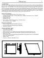
DIGIDRIVER
DIGITILE144
DIGIBAR160
DIGISTRIP40
DIGITUBE
MANUALE UTENTE
USER MANUAL
IT - EN
Music & Lights S.r.l. si riserva ogni diritto di elaborazione in qualsiasi forma delle presenti istruzioni per l’uso.
La riproduzione - anche parziale - per propri scopi commerciali è vietata.
Al fine di migliorare la qualità dei prodotti, la Music&Lights S.r.l. si riserva la facoltà di modificare, in
qualunque momento e senza preavviso, le specifiche menzionate nel presente manuale di istruzioni.
Tutte le revisioni e gli aggiornamenti sono disponibili nella sezione 'Manuali' sul sito www.musiclights.it
REV.003-06/15
DIGI series
INDICE
Sicurezza
Avvertenze generali
Attenzioni e precauzioni per l’installazione
Informazioni generali
4
4
5
1 Descrizione e specifiche tecniche
1. 1 DIGIDRIVER
1. 2 DIGITILE144
1. 3 DIGIBAR160
1. 4 DIGISTRIP40
1. 5 DIGITUBE
1. 6 Elementi di comando e collegamenti
6
7
8
9
10
11
2 Installazione
2. 1 Montaggio DIGIDRIVER
2. 2 Distanza massima di cablaggio
12
12
3 Funzioni e impostazioni
3. 1 Funzionamento
3. 2 Impostazione base
3. 3 Struttura menu DIGIDRIVER
13
14
15
4 Manutenzione
4. 1 Manutenzione e pulizia del sistema
4. 2 Sostituzione fusibile
16
16
Certificato di garanzia
Contenuto dell'imballo:
3
• DIGIDRIVER/DIGITILE144/
DIGIBAR160/DIGISTRIP40/
DIGITUBE
• Manuale utente
DIGI series
4
ATTENZIONE! Prima di effettuare qualsiasi operazione con l’unità, leggere con attenzione
questo manuale e conservarlo accuratamente per riferimenti futuri. Contiene informazioni
importanti riguardo l’installazione, l’uso e la manutenzione dell’unità.
SICUREZZA
Avvertenze generali
• I prodotti a cui questo manuale si riferisce sono conformi alle Direttive della Comunità Europea e pertanto recano la sigla .
• Il dispositivo funziona con pericolosa tensione di rete 230V~. Non intervenire mai al suo interno al di
fuori delle operazioni descritte nel presente manuale; esiste il pericolo di una scarica elettrica.
• È obbligatorio effettuare il collegamento ad un impianto di alimentazione dotato di un’efficiente messa
a terra (apparecchio di Classe I secondo norma EN 60598-1). Si raccomanda, inoltre, di proteggere le
linee di alimentazione delle unità dai contatti indiretti e/o cortocircuiti verso massa tramite l’uso di
interruttori differenziali opportunamente dimensionati.
• Le operazioni di collegamento alla rete di distribuzione dell’energia elettrica devono essere effettuate
da un installatore elettrico qualificato. Verificare che frequenza e tensione della rete corrispondono alla
frequenza ed alla tensione per cui l’unità è predisposta, indicate sulla targhetta dei dati elettrici.
• L’unità non per uso domestico, solo per uso professionale.
• Evitare di utilizzare l’unità:
- in luoghi soggetti a vibrazioni, o a possibili urti;
- in luoghi soggetti ad eccessiva umidità;
- in luoghi a temperatura superiore ai 45°C oppure ai -40°C.
• Evitare che nell’unità penetrino liquidi infiammabili, acqua o oggetti metallici.
• Non smontare e non apportare modifiche all’unità.
• Tutti gli interventi devono essere sempre e solo effettuati da personale tecnico qualificato. Rivolgersi al
più vicino centro di assistenza tecnica autorizzato.
• Se si desidera eliminare il dispositivo definitivamente, consegnarlo
per lo smaltimento ad un’istituzione locale per il riciclaggio.
Attenzioni e precauzioni per l’installazione
• Se il dispositivo dovesse trovarsi ad operare in condizioni differenti da quelle descritte nel presente
manuale, potrebbero verificarsi dei danni; in tal caso la garanzia verrebbe a decadere. Inoltre, ogni altra
operazione potrebbe provocare cortocircuiti, incendi, scosse elettriche, rotture etc.
• Ogni persona coinvolta con l’installazione e la manutenzione di questo prodotto deve essere qualificata e seguire le istruzioni di questo manuale.
• Prima di iniziare qualsiasi operazione di manutenzione o pulizia sull’unità togliere la tensione dalla rete
di alimentazione.
• Nell’eseguire qualsiasi intervento attenersi scrupolosamente a tutte le normative (in materia di sicurezza) vigenti nel paese di utilizzo.
• Installare l’unità in un luogo ben ventilato.
• Mantenere i materiali infiammabili ad una distanza di sicurezza dall’unità.
• Non guardare direttamente il fascio luminoso. Tenete presente che i veloci cambi di luce possono provocare attacchi d’epilessia presso persone fotosensibili o epilettiche.
• Per la pulizia del prodotto non usare solventi tipo acetone o alcool per non danneggiare la finitura
esterna.
DIGI series
5
INFORMAZIONI GENERALI
Spedizioni e reclami
Le merci sono vendute “franco nostra sede” e viaggiano sempre a rischio e pericolo del distributore/cliente. Eventuali avarie e danni dovranno essere contestati al vettore. Ogni reclamo per imballi manomessi
dovrà essere inoltrato entro 8 giorni dal ricevimento della merce.
Garanzie e resi
Il prodotto è coperto da garanzia in base alle vigenti normative. Sul sito www.musiclights.it è possibile
consultare il testo integrale delle “Condizioni Generali di Garanzia”. Si prega, dopo l’acquisto, di procedere
alla registrazione del prodotto sul sito www.musiclights.it. In alternativa il prodotto può essere registrato
compilando e inviando il modulo riportato alla fine del manuale. A tutti gli effetti la validità della garanzia
è avallata unicamente dalla presentazione del certificato di garanzia. Music & Lights constata tramite verifica sui resi la difettosità dichiarata, correlata all’appropriato utilizzo, e l’effettiva validità della garanzia;
provvede quindi alla riparazione dei prodotti, declinando tuttavia ogni obbligo di risarcimento per danni
diretti o indiretti eventualmente derivanti dalla difettosità.
DIGI series
6
- 1 - DESCRIZIONE E SPECIFICHE TECNICHE
1.1 DIGIDRIVER
DIGIDRIVER è il driver che fornisce alimentazione ed elaborazione a tutti i dispositivi della serie DIGI
(DIGITUBE, DIGIBAR, DIGISTRIP e DIGITILE). Può gestire fino a 24 DIGISTRIP, 16 DIGITUBE, 6 DIGIBAR e
6 DIGITILE; dispone di 6 universi DMX e 350W di potenza in uscita, tutto in un’unità rack. DIGIDRIVER è
compatibile con protocolli Art-Net e Kling-Net; convoglia segnale e alimentazione in un unico cavo a 4
poli, offrendo una maggiore stabilità in caso di connessioni a catena con più unità. L’interfaccia utente
consiste in un display black OLED con il quale è possibile gestire le impostazioni, selezionare il protocollo
di funzionamento, l’indirizzo di rete e i modelli di prova.
300
37
107
Specifiche tecniche
1000
• Protocolli di controllo: Art-Net, Kling-Net
• Elettronica a completo controllo digitale con panello di controllo frontale e display OLED
• Funzione di autotest automatico anche in assenza di una console
• Uscita di controllo: connettore XLR 4 poli
• Connessione dati: 2 connettori Ethernet (RJ45) per sorgente dati e link driver secondario
• Numero di universi gestiti: 6 universi
• Canali per ogni universo: 480
1000
• Alimentazione: AC 100-240V, 50/60Hz, connettore Neutrik PowerCon
• Assorbimento massimo: 350W (per gestire 24 DIGISTRIP/16 DIGITUBE/6 DIGITILE/6 DIGIBAR)
• Corpo in acciaio
• Grado di protezione: IP20
• Peso: 2,5 kg
118
• Dimensioni (LxAxP): 483x54x150300
mm
28
1155
150
54
483
Disegno tecnico
Fig.1
DIGI series
7
1.2 DIGITILE144
DIGITILE è un pannello video LED, ideale per il mercato del rental; è dotato di pixel pitch a 25 mm e di una
vasta gamma di accessori ottici con i quali è possibile ottenere aspetti differenti (cover nera e bianco latte
incluse, trasparente su richiesta). Ogni DIGITILE è dotato di 12x12 144 LED RGB/FC, di controllo pixel2pixel
e di un angolo di visione pari a 120°. La meccanica di DIGITILE è stata studiata per garantire una grande
flessibilità per il montaggio su truss attraverso supporti scorrevoli presenti sulla parte posteriore e sul
lato, per collegamenti verticali con più unità. L’unità di controllo DIGIDRIVER esterna è compatibile con
protocolli ArtNet e KlingNet; convoglia segnale e alimentazione in un unico cavo a 4 poli, offrendo una
maggiore stabilità in caso di connessioni a catena con più unità (supporta fino a 6 DIGITILE).
Sorgente luminosa e ottica
• 12x12 (144 in totale) LED SMD5050 RGB/FC ad alta resa luminosa
• Flusso luminoso: cover nera = 725 NIT, cover bianco latte = 2900 NIT, cover trasparente = 3290 NIT
• Controllo Pixel2pixel
• Angolo di visione: 120°
• Pixel pitch: 25 mm
• Sistema di sintesi colore: miscelazione RGB/FullColor (>16 milioni di colori)
• Durata media diodi LED: >50.000 ore
Funzionamento ed elettronica
• Alimentazione e segnale tramite DIGIDRIVER (opzionale)
• Controllo attraverso protocollo Art-Net o Kling-Net
• Canali Art-Net: 432
37
107
Corpo e alimentazione
117
1000
• Robusto profilo in alluminio
• Grado di protezione: IP20
• Staffa scorrevole per truss rigging e hardware verticale per collegamento tra più unità
• Filtro opaco nero (montato), bianco latte (incluso) e trasparente (opzionale)
• Alimentazione: DC36V
• Cablaggio IN/OUT alimentazione e segnale attraverso connessioni XLR4p (massimo 6 unità collegate
ad un singolo DIGIDRIVER)
• Assorbimento medio: 52,5W
117
1000
• Peso: 2,6 kg
• Dimensioni (LxAxP): 300x300x118 mm
118
300
300
Disegno tecnico
Fig.2
1155
8
DIGI series
1.3 DIGIBAR160
DIGIBAR è un dispositivo video LED lineare, ideale per il mercato del rental; è dotato di pixel pitch a 25mm
e di una vasta gamma di accessori ottici con i quali è possibile ottenere aspetti differenti (cover nera e
bianco latte incluse, trasparente su richiesta). Ogni DIGIBAR, lunga 1 metro, è dotata di 4x40 160 LED RGB/
FC, di controllo pixel2pixel e di un angolo di visione pari a 120°. La meccanica di DIGIBAR è stata studiata
per garantire una grande flessibilità per il montaggio su truss attraverso supporti scorrevoli presenti sulla
parte posteriore e sul lato, per collegamenti verticali con più unità. L’unità di controllo DIGIDRIVER esterna
è compatibile con protocolli Art-Net e Kling-Net; convoglia segnale e alimentazione in un unico cavo a
4 poli, offrendo una maggiore stabilità in caso di connessioni a catena con più unità (supporta fino a 6
DIGIBAR).
Sorgente luminosa e ottica
• 4x40 (160 in totale) LED SMD5050 RGB/FC ad alta resa luminosa
• Flusso luminoso: cover nera = 540,20 NIT, cover bianco latte = 2160,80 NIT, cover trasparente = 2586,20
NIT
• Controllo Pixel2pixel
• Angolo di visione: 120°
• Pixel pitch: 25 mm
• Sistema di sintesi colore: miscelazione RGB/FullColor (>16 milioni di colori)
• Durata media diodi LED: >50.000 ore
Funzionamento ed elettronica
• Alimentazione e segnale tramite DIGIDRIVER (opzionale)
• Controllo attraverso protocollo Art-Net o Kling-Net
• Canali Art-Net: 480
Corpo e alimentazione
• Robusto profilo in alluminio
• Grado di protezione: IP20
• Staffa scorrevole per truss rigging e hardware verticale per collegamento tra più unità
• Filtro opaco nero (montato), bianco latte (incluso) e trasparente (opzionale)
• Alimentazione: DC36V
• Cablaggio IN/OUT alimentazione e segnale attraverso connessioni XLR4p (massimo 6 unità collegate
ad un singolo DIGIDRIVER)
• Assorbimento medio: 59,1W
• Peso: 3,7 kg
• Dimensioni (LxAxP): 1000x107x117 mm
117
107
1000
Disegno tecnico
Fig.3
DIGI series
9
1.4 DIGISTRIP40
DIGISTRIP è un dispositivo video LED lineare, ideale per il mercato del rental; è dotato di pixel pitch a 25
mm e di una vasta gamma di accessori ottici con i quali è possibile ottenere aspetti differenti (cover nera
e bianco latte incluse, trasparente su richiesta). Ogni DIGISTRIP, lunga 1 metro, è dotata di 40 LED RGB/FC,
di controllo pixel2pixel e di un angolo di visione pari a 120°. La meccanica di DIGISTRIP è stata studiata
per garantire una grande flessibilità per il montaggio su truss attraverso supporti scorrevoli presenti sulla
parte posteriore e sul lato, per collegamenti verticali con più unità. L’unità di controllo DIGIDRIVER esterna
è compatibile con protocolli Art-Net e Kling-Net; convoglia segnale e alimentazione in un unico cavo a
4 poli, offrendo una maggiore stabilità in caso di connessioni a catena con più unità (supporta fino a 24
DIGISTRIP).
Sorgente luminosa e ottica
• 40 LED SMD5050 RGB/FC ad alta resa luminosa
• Flusso luminoso: cover nera = 206,95 NIT, cover bianco latte = 827,80 NIT, cover trasparente = 1174 NIT
• Controllo Pixel2pixel
• Angolo di visione: 120°
• Pixel pitch: 25 mm
• Sistema di sintesi colore: miscelazione RGB/FullColor (>16 milioni di colori)
• Durata media diodi LED: >50.000 ore
Funzionamento ed elettronica
• Alimentazione e segnale tramite DIGIDRIVER (opzionale)
• Controllo attraverso protocollo Art-Net o Kling-Net
• Canali Art-Net: 120
Corpo e alimentazione
• Robusto profilo in alluminio
• Grado di protezione: IP20
• Staffa scorrevole per truss rigging e hardware verticale per collegamento tra più unità
• Filtro opaco nero (montato), bianco latte (incluso) e trasparente (opzionale)
• Alimentazione: DC36V
• Cablaggio IN/OUT alimentazione e segnale attraverso connessioni XLR4p (massimo 24 unità collegate
ad un singolo DIGIDRIVER)
• Assorbimento medio: 26,7W
• Peso: 2,2 kg
• Dimensioni (LxAxP): 1000x37x117 mm
117
1000
117
37
107
1000
Disegno tecnico
300
118
Fig.4
DIGI series
10
1.5 DIGITUBE
DIGITUBE è un’evoluzione nel campo degli effetti pixel. Con la sua forma tubolare e la capacità di poter
proiettare a 360°, DIGITUBE aggiunge la terza dimensione nella creazione di visual show. Ogni tubo, lungo
1 metro, è dotato di 2 righe da 40 LED RGB/FC e di controllo pixel2pixel. L’unità di controllo DIGIDRIVER
esterna è compatibile con protocolli Art-Net e Kling-Net; convoglia segnale e alimentazione in un unico
cavo a 4 poli, offrendo una maggiore stabilità in caso di connessioni a catena con più unità (supporta fino
a 16 tubi). Grazie al suo design modulare, DIGITUBE può essere montato e configurato con la massima
flessibilità, in sospensione sotto il soffitto, per creare effetti 3D sui tre assi XYZ.
Sorgente luminosa e ottica
• 80 LED SMD5050 RGB/FC (per tubo)
• Controllo Pixel2pixel
• Angolo di visione: 360°
• Pixel pitch: 25 mm
• Sistema di sintesi colore: miscelazione RGB/FullColor (>16 milioni di colori)
• Durata media diodi LED: >50.000 ore
117
107
Funzionamento ed elettronica
• Alimentazione e segnale tramite DIGIDRIVER1000
(opzionale)
• Controllo attraverso protocollo Art-Net o Kling-Net
• Canali Art-Net: 120
37
Corpo e alimentazione
• Tubo acrilico, PCB nera
• Grado di protezione: IP20
• Alimentazione: DC36V
117
• Cablaggio IN/OUT alimentazione e segnale 1000
attraverso connessioni XLR4p (massimo 16 unità collegate
ad un singolo DIGIDRIVER)
• Assorbimento medio: 40W
• Peso: 0,33 kg (per tubo)
• Dimensioni (LxA): 1155x28 mm
118
300
300
28
1155
Disegno tecnico
54
483
150
Fig.5
DIGI series
11
1.6 ELEMENTI DI COMANDO E COLLEGAMENTI
DIGIDRIVER
1
2
DiGi DRIVER
3
4 5
6
7
8
Fig.6
1. FORI DI FISSAGGIO per il montaggio rack
2. PANNELLO DI CONTROLLO con display e 4
pulsanti per accesso e gestione delle diverse
funzioni
3. POWER IN ( PowerCON IN): per il collegamento
ad una presa di rete (100-240V~/50-60Hz)
tramite il cavo rete in dotazione.
4. PORTAFUSIBILE: sostituire un fusibile difettoso
solo con uno dello stesso tipo
5. GND POINT usato per la messa a terra del
dispositivo
6. CONNETTORE DI SEGNALE OUT FEMMINA
7. CONNETTORE RJ45 Art-net IN/OUT (IP
ADDRESS 2)
8. CONNETTORE RJ45 Art-net IN/OUT (IP
ADDRESS 1)
12
DIGI series
- 2 - INSTALLAZIONE
2.1 MONTAGGIO DIGIDRIVER
L‘ unità di gestione e alimentazione DIGIDRIVER deve essere collocata in modo stabile su una superficie
piana non infiammabile, oppure può essere montata in un rack da 19” per mezzo delle viti che devono
essere inserite negli appositi fori presenti sul corpo del dispositivo, come mostrato in figura 7.
Fig.7
2.2 DISTANZA MASSIMA DI CABLAGGIO
Distanza massima di cablaggio tra DIGIDRIVER e primo dispositivo connesso:
• DIGIDRIVER - DIGIBAR160 = 20 m
• DIGIDRIVER - DIGITILE144 = 30 m
• DIGIDRIVER - DIGISTRIP40 = 10 m
• DIGIDRIVER - DIGITUBE = 20 m
Distanza massima di cablaggio tra due dispositivi:
• 2 DIGIBAR160 = 1 m
• 2 DIGITILE144 = 1 m
• 2 DIGISTRIP40 = 1 m
Distanza massima tra DIGIDRIVER e ultimo dispositivo connesso:
• DIGIDRIVER - DIGIBAR160 = 25 m
• DIGIDRIVER - DIGITILE144 = 35 m
• DIGIDRIVER - DIGISTRIP40 = 33 m
DIGI series
13
- 3 - FUNZIONI E IMPOSTAZIONI
3.1 FUNZIONAMENTO
Eseguire il collegamento delle unità secondo lo schema esemplificativo indicato in figura 8. Per accendere
il DIGIDRIVER inserire la spina del cavo di alimentazione in una presa di rete (100-240V~/50-60Hz).
Input segnale:
Ethernet (RJ45)
DIGIDRIVER (1)
DIGIDRIVER (2)
Canali Art-Net: 480
Universi gestiti: 6
DIGIDRIVER (3)
Output:
Driver succ.
Net: 0
Subnet: 0
Universo #1:
Univ. Art-Net = 0
(Univ. DMX = 1)
Net: 0
Subnet: 0
Universo #1:
Univ. Art-Net = 6
(Univ. DMX = 7)
Net: 0
Subnet: 1
Universo #1:
Univ. Art-Net = 0
(Univ. DMX = 17)
Net: 0
Subnet: 0
Universo #2:
Univ. Art-Net = 1
(Univ. DMX = 2)
Net: 0
Subnet: 0
Universo #2:
Univ. Art-Net = 7
(Univ. DMX = 8)
Net: 0
Subnet: 1
Universo #2:
Univ. Art-Net = 1
(Univ. DMX = 18)
Net: 0
Subnet: 0
Universo #3:
Univ. Art-Net = 2
(Univ. DMX = 3)
Net: 0
Subnet: 0
Universo #3:
Univ. Art-Net = 8
(Univ. DMX = 9)
Net: 0
Subnet: 1
Universo #3:
Univ. Art-Net = 2
(Univ. DMX = 19)
Net: 0
Subnet: 0
Universo #4:
Univ. Art-Net = 3
(Univ. DMX = 4)
Net: 0
Subnet: 0
Universo #4:
Univ. Art-Net = 9
(Univ. DMX = 10)
Net: 0
Subnet: 1
Universo #4:
Univ. Art-Net = 3
(Univ. DMX = 20)
Net: 0
Subnet: 0
Universo #5:
Univ. Art-Net = 4
(Univ. DMX = 5)
Net: 0
Subnet: 0
Universo #5:
Univ. Art-Net = 10
(Univ. DMX = 11)
Net: 0
Subnet: 1
Universo #5:
Univ. Art-Net = 4
(Univ. DMX = 21)
Net: 0
Subnet: 0
Universo #6:
Univ. Art-Net = 5
(Univ. DMX = 6)
Net: 0
Subnet: 0
Universo #6:
Univ. Art-Net = 11
(Univ. DMX = 12)
Net: 0
Subnet: 1
Universo #6:
Univ. Art-Net = 5
(Univ. DMX = 22)
DIGITILE144 (x6)
Canali Art-Net: 432 (1 fixture per universo)
DIGITILE144 (x6)
DIGITILE144 (x6)
Fig.8 - Esempio diagramma di connessione
DIGI series
14
3.2 IMPOSTAZIONE BASE
Il DIGIDRIVER dispone di un display OLED e 4 pulsanti per accesso alle funzioni del pannello di controllo
(fig.9).
MENU
Per scorrere il menu
principale o tornare ad
una opzione del menu
precedente
MENU
UP
ENTER
DOWN
UP
Per scorrere attraverso le
diverse funzioni in ordine
discendente o aumentare il
valore della funzione stessa
DOWN
ENTER
Per scorrere attraverso le
diverse funzioni in ordine
ascendente o diminuire il
valore della funzione stessa
Per entrare nel menu selezionato o
confermare il valore attuale della
funzione o l'opzione all'interno di
un menu
Fig.9 - Funzione dei tasti
DIGI series
15
3.3 STRUTTURA MENU DIGIDRIVER
1
Main Level
Programming Levels
Default
Protocol
ð
Art-Net
Kling-Net
Art-Net
2
Auto Address
ð
No - Yes
3
Subnet
ð
0 - 15
4
Universe#1
ð
0 - 15
5
Universe#2
ð
0 - 15
6
Universe#3
ð
0 - 15
7
Universe#4
ð
0 - 15
8
Universe#5
ð
0 - 15
9
Universe#6
ð
0 - 15
10 Pixel Layout
ð
40x24
12x72
11 IP Address #1
ð
2.255.255.1
12 IP Address #2
ð
2.255.255.2
13 Device ID
ð
101760422
14 Test Output
ð
Red
Green
Blue
White
Fade
Scroll
15 Factory Reset
No - Yes
Description
No
Auto LED Address
0
Sets the subnet address
0
Sets the universe #1 address
1
Sets the universe #2 address
2
Sets the universe #3 address
3
Sets the universe #4 address
4
Sets the universe #5 address
5
Sets the universe #6 address
40x24
40x24 (6 x DIGIBAR160)
12x72 (6 x DIGITILE144)
2.255.255.1
Network card No 1
2.255.255.2
Network card No 2
16
DIGI series
- 4 - MANUTENZIONE
4.1 MANUTENZIONE E PULIZIA DEL SISTEMA
• Durante gli interventi, assicurarsi che l’area sotto il luogo di installazione sia libera da personale non
qualificato.
• Tutte le viti utilizzate per l’installazione dell’unità e le sue parti devono essere assicurate saldamente e
non devono essere corrose.
• Alloggiamenti, elementi di fissaggio e di installazione (soffitto, truss, sospensioni) devono essere totalmente esenti da qualsiasi deformazione.
• I cavi di alimentazione devono essere in condizione impeccabile e devono essere sostituiti immediatamente nel momento in cui anche un piccolo problema viene rilevato.
Per mantenere prestazioni ottimali e ridurre al minimo l’usura, è necessario pulire questo prodotto frequentemente. Uso e l’ambiente sono fattori che contribuiscono a determinare la frequenza di pulizia.
Come regola generale, il dispositivo deve essere pulito almeno due volte al mese. L’accumulo di polvere
riduce la luminosità e può causare il surriscaldamento. L’utilizzo e l’ambiente sono fattori che contribuiscono a determinare la frequenza di pulizia.
Per la pulizia del prodotto, seguire le istruzioni riportate di seguito:
• Scollegare il dispositivo dall’alimentazione elettrica.
• Attendere finché l’unità non si sia raffreddata.
• Utilizzare un compressore d’aria o una spazzola morbida per rimuovere la polvere accumulata sulla
superficie esterna.
• Per la pulizia usare un panno morbido, pulito e un detergente per vetri come si trovano in commercio.
• Delicatamente lucidare le superfici fino a che non siano prive di lanugine.
NOTA - Non aprire il prodotto per la pulizia o la manutenzione.
4.2 SOSTITUZIONE FUSIBILE
1. Assicurarsi di scollegare il cavo di alimentazione dell’unità prima di sostituire un fusibile bruciato con
uno dello stesso tipo e valore.
2. Con un cacciavite, rimuovere il portafusibile dalla sua sede e il fusibile bruciato dal suo supporto; sostituire il fusibile con uno identico per tipologia e valore.
3. Inserire il portafusibile al suo posto e ricollegare l’alimentazione.
Fig.10
All rights reserved by Music & Lights S.r.l. No part of this instruction manual may be
reproduced in any form or by any means for any commercial use.
In order to improve the quality of products, Music&Lights S.r.l. reserves the right to modify the
characteristics stated in this instruction manual at any time and without prior notice.
All revisions and updates are available in the ‘manuals’ section on site www.musiclights.it
DIGI series
TABLE OF CONTENTS
Safety
General instructions
Warnings and installation precautions
General information
2
2
3
1 Description and Technical specifications
1. 1 DIGIDRIVER
1. 2 DIGITILE144
1. 3 DIGIBAR160
1. 4 DIGISTRIP40
1. 5 DIGITUBE
1. 6 Operating elements and connections
4
5
6
7
8
9
2 Installation
2. 1 Mounting DIGIDRIVER
2. 2 Maximum cable distance
10
10
3 Functions and settings
3. 1 Operation
3. 2 Basic setup
3. 3 DIGIDRIVER menu structure
11
12
13
4 Maintenance
4. 1 Maintenance and cleaning the unit
4. 2 Fuse replacement
14
14
Warranty
Packing content
1
• DIGIDRIVER/DIGITILE144/
DIGIBAR160/DIGISTRIP40/
DIGITUBE
• User manual
DIGI series
2
WARNING! Before carrying out any operations with the unit, carefully read this instruction
manual and keep it with cure for future reference. It contains important information about
the installation, usage and maintenance of the unit.
SAFETY
General instruction
• The products referred to in this manual conform to the European Community Directives and are therefore marked with .
• The unit is supplied with hazardous network voltage (230V~). Leave servicing to skilled personnel only.
Never make any modifications on the unit not described in this instruction manual, otherwise you will
risk an electric shock.
• Connection of the power adapter must be made to a power supply system fitted with efficient earthing (Class I appliance according to standard EN 60598-1). It is, moreover, recommended to protect the
supply lines of the units from indirect contact and/or shorting to earth by using appropriately sized
residual current devices.
• The connection to the main network of electric distribution must be carried out by a qualified electrical installer. Check that the voltage correspond to those for which the unit is designed as given on the
electrical data label.
• This unit is not for home use, only professional applications.
• Never use the fixture under the following conditions:
- in places subject to vibrations or bumps;
- in places subject to excessive humidity;
- in places with a temperature of over 45 °C or -40°C.
• Make certain that no inflammable liquids, water or metal objects enter the fixture.
• Do not dismantle or modify the fixture.
• All work must always be carried out by qualified technical personnel. Contact the nearest sales point for
an inspection or contact the manufacturer directly.
• If the unit is to be put out of operation definitively, take it to a local recycling
plant for a disposal which is not harmful to the environment.
Warnings and installation precautions
• If this device will be operated in any way different to the one described in this manual, it may suffer
damage and the guarantee becomes void. Furthermore, any other operation may lead to dangers like
short circuit, burns, electric shock, etc.
• Every person involved with installation and maintenance of this device have to be qualified and follow
the instructions of this manual.
• Before starting any maintenance work or cleaning the projector, cut off power from the main supply.
• Always additionally secure the projector with the safety rope. When carrying out any work, always comply scrupulously with all the regulations (particularly regarding safety) currently in force in the country
in which the fixture’s being used.
• Install the fixture in a well ventilated place.
• Keep any inflammable material at a safe distance from the fixture.
• Never look directly at the light beam. Please note that fast changes in lighting, e. g. flashing light, may
trigger epileptic seizures in photosensitive persons or persons with epilepsy.
• When cleaning product, please do not use solvents such as acetone or alcohol, since they may damage
the of the unit outer finish and the printings on the panels.
DIGI series
3
GENERAL INFORMATION
Shipments and claims
The goods are sold “ex works” and always travel at the risk and danger of the distributor. Eventual damage will have to be claimed to the freight forwarder. Any claim for broken packs will have to be forwarded
within 8 days from the reception of the goods.
Warranty and returns
The guarantee covers the fixture in compliance with existing regulations. You can find the full version of
the “General Guarantee Conditions” on our web site www.musiclights.it. Please remember to register the
piece of equipment soon after you purchase it, logging on www.musiclights.it. The product can be also
registered filling in and sending the form available on your guarantee certificate. For all purposes, the validity of the guarantee is endorsed solely on presentation of the guarantee certificate. Music & Lights will
verify the validity of the claim through examination of the defect in relation to proper use and the actual
validity of the guarantee. Music & Lights will eventually provide replacement or repair of the products declining, however, any obligation of compensation for direct or indirect damage resulting from faultiness.
DIGI series
4
- 1 - DESCRIPTION AND TECHNICAL SPECIFICATIONS
1.1 DIGIDRIVER
DIGIDRIVER is a driver which provides power and processing to all the fixtures of the DIGI series (tube,
strip, bar, tile). It controls up to 24 DIGISTRIP, 16 DIGITUBE, 6 DIGIBAR, 6 DIGITILE, offering 6 DMX universes and 350W of power in out, in a one rack unit. DIGIDRIVER is compatible with both Art-Net and
Kling-Net protocol and runs signal and power over a 4 pole XLR cable that allow wiring of units in a chain.
The user interface consists in a black OLED display for settings, protocol selection, Network address and
test patterns.
37
107
Technical Specifications
• Control protocols: Art-Net, Kling-Net
1000
• Electronics in full digital control with front panel and OLED display
• Automatic self-test function even in the absence of a console
• Control output: 4-pin XLR connector
• Data Connection: two Ethernet connectors (RJ45) for data source and secondary driver link
• Universes: 6 universes
• Channels for universe: 480
• Power supply: AC 100-240V, 50/60Hz, Neutrik PowerCon
1000
• Maximum consumption: 350W (to handle 24 DIGISTRIP/16 DIGITUBE/6
DIGITILE/6 DIGIBAR)
• Steel body
• Internal Protection: IP20
• Weight: 2,5 kg
• Dimensions (WxHxD): 483x54x150 mm
118
300
300
28
1155
150
54
483
Technical drawing
Fig.1
DIGI series
5
1.2 DIGITILE144
DIGITILE is a LED video panel for the rental market wih 25 mm pixel pitch and an extensive range of optical
accessories for a wide variety of looks (black and white milk included, transparent on demand). Each panel
features 12x12 144 LED RGB/FC LEDs with individual pixel control, 120° viewing angle. The mechanics of
DIGITILE have been studied to grant a great mounting flexibility through a sliding hardwares on the back
for truss application and on the side for multiple vertical linking. The external control unit DIGIDRIVER is
compatible with ArtNet and KlingNet protocol, and runs both signal and power over a 4 poles cable that
provides greater stability and connection in daisy chain (up to 6 DIGITILE).
Light source and optics
• 12x12 (144 total) SMD5050 RGB/FC high-efficiency LEDs
• Luminous flux: black cover = 725 NIT, milky cover = 2900 NIT, transparent cover = 3290 NIT
• Pixel2pixel control
• Viewing angle: 120°
• Pixel pitch: 25 mm
• Color synthesis: RGB/FullColor mixing (>16 million colors)
• LEDs average life span: >50’000h
Electronics and features
• Power and signal through DIGIDRIVER (optional)
• Art-Net and Kling-Net control protocol supported
• Channels Art-Net: 432
117
107
Structure and Power supply
• Sturdy aluminum profile
1000
• Internal Protection: IP20
• Sliding bracket for truss rigging and vertical hardware for connection of more units
• Black matte filter (mounted), white milk filter (included), transparent filter (optional)
• Power unit: DC36V
• IN/OUT power wiring and signal through connections XLR4p (max 6 units on a DIGIDRIVER)
• Power consumption: 52,5W
• Weight: 2,6 kg
1000
• Dimensions (WxHxD): 300x300x118 mm
37
117
118
300
300
Technical drawing
1155
Fig.2
6
DIGI series
1.3 DIGIBAR160
DIGIBAR is a linear LED video fixture for the rental market wih 25mm pixel pitch and an extensive range
of optical accessories for a wide variety of looks (black and white milk included, transparent on demand).
Each bar features 4x40 160 LED RGB/FC LEDs with individual pixel control, 1 meter long, 120° viewing
angle. The mechanics of DIGIBAR have been studied to grant a great mounting flexibility through a sliding
hardwares on the back for truss application and on the side for multiple vertical linking. The external control unit DIGIDRIVER is compatible with Art-Net and Kling-Net protocol, and runs both signal and power
over a 4 poles cable that provides greater stability and connection in daisy chain (up to 6 DIGIBAR).
Light source and optics
• 4x40 (160 total) SMD5050 RGB/FC high-efficiency LEDs
• Luminous flux: black cover = 540,20 NIT, milky cover = 2160,80 NIT, transparent cover = 2586,20 NIT
• Pixel2pixel control
• Viewing angle: 120°
• Pixel pitch: 25 mm
• Color synthesis: RGB/FullColor mixing (>16 million colors)
• LEDs average life span: >50’000h
Electronics and features
• Power and signal through DIGIDRIVER (optional)
• Art-Net and Kling-Net control protocol supported
• Channels Art-Net: 480
Structure and Power supply
• Sturdy aluminum profile
• Internal Protection: IP20
• Sliding bracket for truss rigging and vertical hardware for connection of more units
• Black matte filter (mounted), white milk filter (included), transparent filter (optional)
• Power unit: DC36V
• IN/OUT power wiring and signal through connections XLR4p (max 6 units on a DIGIDRIVER)
• Power consumption: 59,1W
• Weight: 3,7 kg
• Dimensions (WxHxD): 1000x107x117 mm
117
107
1000
Technical drawing
Fig.3
1000
117
DIGI series
7
1.4 DIGISTRIP40
DIGISTRIP is a linear LED video fixture for the rental market wih 25 mm pixel pitch and an extensive range
of optical accessories for a wide variety of looks (black and white milk included, transparent on demand).
Each strip features 40 LED RGB/FC LEDs with individual pixel control, 1 meter long, 120° viewing angle. The
mechanics of DIGISTRIP have been studied to grant a great mounting flexibility through a sliding hardwares on the back for truss application and on the side for multiple vertical linking. The external control
unit DIGIDRIVER is compatible with Art-Net and Kling-Net protocol, and runs both signal and power over a
4 poles cable that provides greater stability and connection in daisy chain (up to 24 DIGISTRIP).
Light source and optics
• 40 SMD5050 RGB/FC high-efficiency LEDs
• Luminous flux: black cover = 206,95 NIT, milky cover = 827,80 NIT, transparent cover = 1174 NIT
• Pixel2pixel control
• Viewing angle: 120°
• Pixel pitch: 25 mm
• Color synthesis: RGB/FullColor mixing (>16 million colors)
• LEDs average life span: >50’000h
Electronics and features
• Power and signal through DIGIDRIVER (optional)
• Art-Net and Kling-Net control protocol supported
• Channels Art-Net: 120
Structure and Power supply
• Sturdy aluminum profile
• Internal Protection: IP20
• Sliding bracket for truss rigging and vertical hardware for connection of more units
• Black matte filter (mounted), white milk filter (included), transparent filter (optional)
• Power unit: DC36V
• IN/OUT power wiring and signal through connections XLR4p (max 24 units on a DIGIDRIVER)
• Power consumption: 26,7W
• Weight: 2,2 kg
• Dimensions (WxHxD): 1000x37x117 mm
117
1000
117
37
107
1000
Technical drawing
300
118
Fig.4
DIGI series
8
1.5 DIGITUBE
DIGITUBE is an evolution in the range of pixel effects, adding the 3rd dimensions in the creation of visual
shows through its tubular shapes and capacity to project on 360°. Each tube is equipped with 2 lines of 40
RGB/FC LEDs with individual pixel control, 1 meter long. The external control unit DIGIDRIVER is compatible with Art-Net and Kling-Net protocol, and runs both signal and power over a 4 poles cable that provides greater stability and connection in daisy chain (up to 16 tubes). Its modular design allows DIGITUBE
to be mounted and configured with maximum flexibility, such as suspended below ceiling to create 3D
effects on XYZ axes.
Light source and optics
• 80 SMD5050 RGB/FC LEDs (each tube)
• Pixel2pixel control
• Viewing angle: 360°
• Pixel pitch: 25 mm
• Color synthesis: RGB/FullColor mixing (>16 million colors)
• LEDs average life span: >50’000h
Electronics and features
1000
• Power and signal through DIGIDRIVER (optional)
• Art-Net and Kling-Net control protocol supported
• Art-Net channels: 120
107
117
37
Structure and Power supply
• Acrylic tube, black PCB
• Internal Protection: IP20
• Power unit: DC36V
117
1000
• IN/OUT power wiring and signal through connections XLR4p (max 16 units on a DIGIDRIVER)
• Power consumption: 40W
• Weight: 0,33 kg (each tube)
• Dimensions (WxH): 1155x28 mm
118
300
300
28
1155
Technical drawing
483
150
54
Fig.5
DIGI series
9
1.6 OPERATING ELEMENTS AND CONNECTIONS
DIGIDRIVER
1
2
DiGi DRIVER
3
4 5
6
7
8
Fig.6
1. MOUNTING HOLES for fixing the rack
2. CONTROL PANEL with display and 4 buttons
used to access the control panel functions
and manage them.
3. POWER IN (PowerCON IN) mains plug for
connection to a socket (100-240V~/50/60Hz)
via the supplied mains cable.
4. FUSE: Replace a blown fuse with one of the
same type
5. GND POINT used for the grounding of the
device
6. SIGNAL OUT FEMALE CONNECTOR
7. CONNECTOR RJ45 Art-Net IN/OUT (IP
ADDRESS 2)
8. CONNECTOR RJ45 Art-Net IN/OUT (IP
ADDRESS 1)
10
DIGI series
- 2 - INSTALLATION
2.1 MOUNTING DIGIDRIVER
The management and power unit DIGIDRIVER should be placed on a non-flammable flat surface in any
orientation or fixed by four screws in a 19” rack. There are four mounting holes on the housing as shown
in figure 7.
Fig.7
2.2 MAXIMUM CABLE DISTANCE
Max cable distance between DIGIDRIVER - first fixture connected:
• DIGIDRIVER - DIGIBAR160 = 20 m
• DIGIDRIVER - DIGITILE144 = 30 m
• DIGIDRIVER - DIGISTRIP40 = 10 m
• DIGIDRIVER - DIGITUBE = 20 m
Max cable distance between two fixtures:
• 2 DIGIBAR160 = 1 m
• 2 DIGITILE144 = 1 m
• 2 DIGISTRIP40 = 1 m
Max distance between DIGIDRIVER - last fixture connected:
• DIGIDRIVER - DIGIBAR160 = 25 m
• DIGIDRIVER - DIGITILE144 = 35 m
• DIGIDRIVER - DIGISTRIP40 = 33 m
DIGI series
11
- 3 - FUNCTIONS AND SETTINGS
3.1 OPERATION
Connect the unit according to the connection example shown in Figure 8. Plug the power cord into a wall
socket (100-240V~/50-60Hz) to turn on the DIGIDRIVER.
Signal input:
Ethernet (RJ45)
DIGIDRIVER (1)
Art-Net channels: 480
Universes: 6
DIGIDRIVER (2)
DIGIDRIVER (3)
Output:
Next driver
Net: 0
Subnet: 0
Universe #1:
Art-Net univ. = 0
(DMX univ. = 1)
Net: 0
Subnet: 0
Universe #1:
Art-Net univ. = 6
(DMX univ. = 7)
Net: 0
Subnet: 1
Universe #1:
Art-Net univ. = 0
(DMX univ. = 17)
Net: 0
Subnet: 0
Universe #2:
Art-Net univ. = 1
(DMX univ. = 2)
Net: 0
Subnet: 0
Universe #2:
Art-Net univ. = 7
(DMX univ. = 8)
Net: 0
Subnet: 1
Universe #2:
Art-Net univ. = 1
(DMX univ. = 18)
Net: 0
Subnet: 0
Universe #3:
Art-Net univ. = 2
(DMX univ. = 3)
Net: 0
Subnet: 0
Universe #3:
Art-Net univ. = 8
(DMX univ. = 9)
Net: 0
Subnet: 1
Universe #3:
Art-Net univ. = 2
(DMX univ. = 19)
Net: 0
Subnet: 0
Universe #4:
Art-Net univ. = 3
(DMX univ. = 4)
Net: 0
Subnet: 0
Universe #4:
Art-Net univ. = 9
(DMX univ. = 10)
Net: 0
Subnet: 1
Universe #4:
Art-Net univ. = 3
(DMX univ. = 20)
Net: 0
Subnet: 0
Universe #5:
Art-Net univ. = 4
(DMX univ. = 5)
Net: 0
Subnet: 0
Universe #5:
Art-Net univ. = 10
(DMX univ. = 11)
Net: 0
Subnet: 1
Universe #5:
Art-Net univ. = 4
(DMX univ. = 21)
Net: 0
Subnet: 0
Universe #6:
Art-Net univ. = 5
(DMX univ. = 6)
Net: 0
Subnet: 0
Universe #6:
Art-Net univ. = 11
(DMX univ. = 12)
Net: 0
Subnet: 1
Universe #6:
Art-Net univ. = 5
(DMX univ. = 22)
DIGITILE144 (x6)
Art-Net channels: 432 (1 fixture for universe)
DIGITILE144 (x6)
DIGITILE144 (x6)
Fig.8 - Example wiring diagram
DIGI series
12
3.2 BASIC SETUP
The DIGIDRIVER has an OLED display and 4 buttons for access to the functions of the control panel (fig.9).
MENU
MENU
UP
ENTER
DOWN
UP
Used to scroll down the
Scrolls up the list of options or
menu options or to return a selects a higher value
previous menu option
DOWN
Scrolls down the list of
options or selects a lower
value
ENTER
Activates a menu option or a
selected value
Fig.9 - Functions of the buttons
DIGI series
13
3.3 DIGIDRIVER MENU STRUCTURE
1
Main Level
Programming Levels
Default
Protocol
ð
Art-Net
Kling-Net
Art-Net
2
Auto Address
ð
No - Yes
3
Subnet
ð
0 - 15
4
Universe#1
ð
0 - 15
5
Universe#2
ð
0 - 15
6
Universe#3
ð
0 - 15
7
Universe#4
ð
0 - 15
8
Universe#5
ð
0 - 15
9
Universe#6
ð
0 - 15
10 Pixel Layout
ð
40x24
12x72
11 IP Address #1
ð
2.255.255.1
12 IP Address #2
ð
2.255.255.2
13 Device ID
ð
101760422
14 Test Output
ð
Red
Green
Blue
White
Fade
Scroll
15 Factory Reset
No - Yes
Description
No
Auto LED Address
0
Sets the subnet address
0
Sets the universe #1 address
1
Sets the universe #2 address
2
Sets the universe #3 address
3
Sets the universe #4 address
4
Sets the universe #5 address
5
Sets the universe #6 address
40x24
40x24 (6 x DIGIBAR160)
12x72 (6 x DIGITILE144)
2.255.255.1
Network card No 1
2.255.255.2
Network card No 2
14
DIGI series
- 4 - MAINTENANCE
4.1 MAINTENANCE AND CLEANING THE UNIT
• Make sure the area below the installation place is free from unwanted persons during setup.
• All screws used for installing the device and any of its parts should be tightly fastened and should not
be corroded.
• Housings, fixations and installation spots (ceiling, trusses, suspensions) should be totally free from any
deformation.
• The main cables must be in impeccable condition and should be replaced immediately even when a
small problem is detected.
To maintain optimum performance and minimize wear, you should clean this product frequently. Usage
and environment are contributing factors in determining the cleaning frequency.
As a rule, clean this product at least twice a month. Dust build-up reduces light output performance and
can cause overheating. This can lead to reduced light source life and increased mechanical wear.
Cleaning the unit:
• Unplug the product.
• Wait until the product is at room temperature.
• Use a vacuum (or dry compressed air) and a soft brush to remove dust collected on the external vents
and accessible internal components.
• Clean all external surfaces with a mild solution of non-ammonia glass cleaner or isopropyl alcohol.
• Apply a solution directly to a soft, lint-free cotton cloth or a lens cleaning tissue.
NOTE - Do not open this product for cleaning or servicing.
4.2 FUSE REPLACEMENT
1. Disconnect this product from the power outlet.
2. Remove the safety cap by a screwdriver.
3. Replace the blown fuse with a fuse of the exact same type and rating.
4. Install the safety cap, and reconnect power.
Fig.10
• Si prega, dopo l’acquisto, di
procedere alla registrazione del
prodotto sul sito www.musiclights.it.
In alternativa il prodotto può essere
registrato compilando e inviando il
modulo riportato sul retro.
• Sono esclusi i guasti causati da
imperizia e da uso non appropriato
dell’apparecchio.
• La garanzia non ha più alcun effetto
qualora l’apparecchio sia stato
manomesso.
• La garanzia non prevede la
sostituzione dell’apparecchio.
• Sono escluse dalla garanzia le parti
esterne, le lampade, le manopole, gli
interruttori e le parti asportabili.
• Le spese di trasporto e i rischi
conseguenti sono a carico del
possessore dell’apparecchio.
• A tutti gli effetti la validità della
garanzia è avallata unicamente
dalla presentazione del certificato di
garanzia.
Estratto dalle
Condizioni Generali di Garanzia
Il prodotto è coperto da garanzia
in base alle vigenti normative.
Sul sito www.musiclights.it è
possibile consultare il testo
integrale delle “Condizioni
Generali di Garanzia”.
• Please remember to register the
piece of equipment soon after you
purchase it, logging on
www.musiclights.it. The product
can be also registered filling in and
sending the form available on your
guarantee certificate.
• Defects caused by inexperience
and incorrect handling of the
equipment are excluded.
• The guarantee will no longer be
effective if the equipment has
been tampered.
• The guarantee makes no provision
for the replacement of the
equipment.
• External parts, lamps, handles,
switches and removable parts are
not included in the guarantee.
• Transport costs and subsequent
risks are responsibility of the
owner of the equipment.
• For all purposes, the validity of
the guarantee is endorsed solely
on presentation of the guarantee
certificate.
Abstract
General Guarantee Conditions
The guarantee covers the unit
in compliance with existing
regulations. You can find the
full version of the “General
Guarantee Conditions” on our
web site www.musiclights.it.
CERTIFICATO DI GARANZIA
GUARANTEE CERTIFICATE
"
Place Stamp Here
Affrancare
Spett.le
Music&Lights S.r.l.
Via Appia Km 136.200
04020 Itri (LT) Italy
"
"
SURNAME / COGNOME
Purchased by / Acquistato da
SERIAL N° / SERIE N°
MODEL / MODELLO
SURNAME / COGNOME
Purchased by / Acquistato da
SERIAL N° / SERIE N°
MODEL / MODELLO
CITY / CITTà
ADDRESS / VIA
NAME / NOME
N.
NAME / NOME
ADDRESS / VIA
CITY / CITTA’
Dealer’s stamp
and signature
Timbro e firma
del Rivenditore
Dealer’s stamp
and signature
ZIP CODE / C.A.P.
Timbro e firma
del Rivenditore
Purchasing date
Data acquisto
PROV.
Purchasing date
Data acquisto
FORM TO BE FILLED IN AND KEPT / CEDOLA DA COMPILARE E CONSERVARE
ZIP CODE / C.A.P.
FORM TO BE FILLED IN AND MAILED / CEDOLA DA COMPILARE E SPEDIRE
N.
PROV.
©2015 Music & Lights S.r.l.
PROLIGHTS is a brand of Music & Lights S.r.l .company.
Via Appia, km 136,200 - 04020 Itri (LT) - ITALY
Phone +39 0771 72190 - Fax +39 0771 721955
www.musiclights.it - email: [email protected]
ISO 9001:2008 Certified Company
PROLIGHTS è un brand di proprietà della Music & Lights S.r.l.
MUSIC & LIGHTS S.r.l.