1
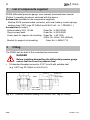
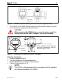
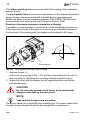
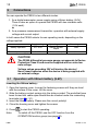
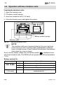
Operating manual PE300 A0189−3.1 en , PE300 Contents 3 Page Safety instructions . . . . . . . . . . . . . . . . . . . . . . . . . . . . . . . . . . . . . . . . . . . . . . . 4 2 Fitting . . . . . . . . . . . . . . . . . . . . . . . . . . . . . . . . . . . . . . . . . . . . . . . . . . . . . . . . 8 3 Connections . . . . . . . . . . . . . . . . . . . . . . . . . . . . . . . . . . . . . . . . . . . . . . . . 12 3.1 Operation with lithium battery (3.6V) . . . . . . . . . . . . . . . . . . . . . . . . 12 3.2 Operation with two miniature cells . . . . . . . . . . . . . . . . . . . . . . . . . . 14 3.3 Operation with external supply voltage . . . . . . . . . . . . . . . . . . . . . . 15 3.4 Operation with relay board . . . . . . . . . . . . . . . . . . . . . . . . . . . . . . . . 18 3.5 Relay contacts circuit logic . . . . . . . . . . . . . . . . . . . . . . . . . . . . . . . . 18 4 Commissioning . . . . . . . . . . . . . . . . . . . . . . . . . . . . . . . . . . . . . . . . . . . . . 19 5 Multi-function display . . . . . . . . . . . . . . . . . . . . . . . . . . . . . . . . . . . . . . . 20 5.1 Trend indicator . . . . . . . . . . . . . . . . . . . . . . . . . . . . . . . . . . . . . . . . . . . 20 5.2 Digital measured value display . . . . . . . . . . . . . . . . . . . . . . . . . . . . . 20 5.3 Bar graph . . . . . . . . . . . . . . . . . . . . . . . . . . . . . . . . . . . . . . . . . . . . . . . 21 5.4 Menu block . . . . . . . . . . . . . . . . . . . . . . . . . . . . . . . . . . . . . . . . . . . . . . 21 5.5 Text box (units/function field) . . . . . . . . . . . . . . . . . . . . . . . . . . . . . . 21 5.6 Symbol bar . . . . . . . . . . . . . . . . . . . . . . . . . . . . . . . . . . . . . . . . . . . . . . 22 5.6.1 Battery symbol . . . . . . . . . . . . . . . . . . . . . . . . . . . . . . . . . . . . . 22 5.6.2 Input lock . . . . . . . . . . . . . . . . . . . . . . . . . . . . . . . . . . . . . . . . . . 22 5.6.3 Limit value/hysteresis warning . . . . . . . . . . . . . . . . . . . . . . . . 22 5.6.4 Analogue output warning . . . . . . . . . . . . . . . . . . . . . . . . . . . . 22 5.6.5 MIN/MAX . . . . . . . . . . . . . . . . . . . . . . . . . . . . . . . . . . . . . . . . . . 22 6 Button functions . . . . . . . . . . . . . . . . . . . . . . . . . . . . . . . . . . . . . . . . . . . . 23 6.1 Operating . . . . . . . . . . . . . . . . . . . . . . . . . . . . . . . . . . . . . . . . . . . . . . . 24 6.2 Overview of operating functions . . . . . . . . . . . . . . . . . . . . . . . . . . . . 25 6.3 Functions . . . . . . . . . . . . . . . . . . . . . . . . . . . . . . . . . . . . . . . . . . . . . . . 25 6.3.1 OPERATION group . . . . . . . . . . . . . . . . . . . . . . . . . . . . . . . . . 25 6.3.2 CONFIG group . . . . . . . . . . . . . . . . . . . . . . . . . . . . . . . . . . . . . 26 6.3.3 SERVICE group . . . . . . . . . . . . . . . . . . . . . . . . . . . . . . . . . . . . 29 6.3.4 SPECIAL group . . . . . . . . . . . . . . . . . . . . . . . . . . . . . . . . . . . . 30 6.4 Typical settings . . . . . . . . . . . . . . . . . . . . . . . . . . . . . . . . . . . . . . . . . . 35 7 Overview of operating functions . . . . . . . . . . . . . . . . . . . . . . . . . . . . . 40 8 Technical Data . . . . . . . . . . . . . . . . . . . . . . . . . . . . . . . . . . . . . . . . . . . . . . 42 9 Dimensions . . . . . . . . . . . . . . . . . . . . . . . . . . . . . . . . . . . . . . . . . . . . . . . . 45 10 Adjustment ranges and factory settings for PE300 . . . . . . . . . . . . . 46 11 Options for PE300 . . . . . . . . . . . . . . . . . . . . . . . . . . . . . . . . . . . . . . . . . . . 50 12 Copy of Declaration of Conformity . . . . . . . . . . . . . . . . . . . . . . . . . . . 52 13 Keyword index . . . . . . . . . . . . . . . . . . . . . . . . . . . . . . . . . . . . . . . . . . . . . . 54 A0189−3.1 en HBM 4 , PE300 Safety instructions Use in accordance with the regulations The PE300 digital differential pressure gauge is to be used exclusively for pressure measurement tasks and directly related control tasks. Use for any additional purpose shall be deemed to be not in accordance with the regulations. To ensure safe operation the differential pressure gauge must be used only in accordance with the information in the User Manual. It is also essential to observe the appropriate legal and safety regulations for the application concerned during use. The same applies to the use of accessories. The differential pressure gauge is not a safety device even when used in accordance with the regulations. Perfectly safe operation of the differential pressure gauge requires proper transport, technically correct storage, installation and assembly as well as careful operation and maintenance. General dangers of failing to follow the safety instructions The PE300 digital differential pressure gauge is a state-of-the-art device and is safe to operate. The differential pressure gauge may give rise to further dangers if it is inappropriately installed and operated by untrained personnel. Any person instructed to carry out installation, commissioning, maintenance or repair of the differential pressure gauge must have read and understood the User Manual and in particular the technical safety instructions. HBM A0189−3.1 en 5 , PE300 Remaining dangers The scope of supply and list of components supplied with the differential pressure gauge cover only part of the scope of measurement technology. In addition, equipment planners, installers and operators should plan, implement and respond to the safety engineering considerations of measurement technology in such a way as to minimise remaining dangers. Existing regulations on the subject must be observed. Reference must be made to remaining dangers connected with measurement technology. If there is any risk of remaining dangers when working with the PE300, it is pointed out in this introduction by means of the following symbols: DANGER Symbol: Meaning: Maximum danger level Warns of an imminently dangerous situation in which failure to comply with safety requirements will result in death or serious physical injury. WARNING Symbol: Meaning: Potentially dangerous situation Warns of a potentially dangerous situation in which failure to comply with safety requirements can result in death or serious physical injury. CAUTION Symbol: Meaning: Potentially dangerous situation Warns of a potentially dangerous situation in which failure to comply with safety requirements could result in damage to property or some form of physical injury. A0189−3.1 en HBM 6 , PE300 Symbols indicating application notes and useful information: NOTE Symbol: Means that important information about the product or its handling is being given. Symbol: Meaning: CE mark The CE mark enables the manufacturer to guarantee that the product complies with the requirements of the relevant EC directives (see Declaration of Conformity at the end of this document). Working safely − particularly if protected by passwords − Modifications to settings in and assembly and service work may be carried out only by trained and authorised personnel. Error messages must not be ignored. The reason for the error must be removed before further use. Conditions on site Protect the device from moisture or atmospheric influences such as rain, snow, etc. Maintenance and cleaning The PE300 digital differential pressure gauge is maintenance-free. Please note the following points when cleaning the housing: Clean the housing with a soft, slightly damp (not wet!) cloth. On no account use solvents, since these may damage the display. When cleaning, ensure that no liquid gets into the device. HBM A0189−3.1 en 7 , PE300 Conversions and modifications The differential pressure gauge must not be modified from the design or safety engineering point of view except with our express agreement. Any modification shall exclude all liability on our part for any damage resulting therefrom. In particular, any repairs, soldering work on motherboards or replacement of components is prohibited. Repairs may be carried out only by HBM. Qualified personnel This instrument is only to be installed and used by qualified personnel strictly in accordance with the technical data and with the safety rules and regulations which follow. It is also essential to observe the appropriate legal and safety regulations for the application concerned during use. The same applies to the use of accessories. Qualified personnel means persons entrusted with the installation, assembly, commissioning and operation of the product who possess the appropriate qualifications for their function. Accident prevention Even though the specified pressure in the destructive range is a multiple of the final value of the measuring range, the relevant accident prevention regulations of the trade safety associations must be taken into consideration. Thus, for example, a burst protector is to be provided on the transducer where conditions cannot be perfectly defined. Recalibration and repair When you send the transducer for calibration or repair to HBM, please specify the pressure medium used. Traces of the medium can always remain in the measuring bore. We need this information to act adequately and, if required, select the appropriate cleaning agent. If no medium has been specified, we must possibly refuse to perform calibration or repair. A0189−3.1 en HBM 8 1 , PE300 List of components supplied PE300 differential pressure gauge, user manual; shortened user manual (Digibar II operating functions) enclosed with the device. Accessories (included in the components supplied): Skintop PG16 screwed cable connector, with seal, battery contact springs, sealing rings (USIT rings 22.7x30x2 and 8.5x13.4x1; for 1-PE300A1...) Accessories (to order): Lithium battery 3.6V 13.5Ah Order No. 3−3319.0009 Plug-in power pack Order No. 3−3318.0002 Power pack for support rail mounting Order No. 1−NT101A, (230V, 50...60Hz /15V=650mA) Bracket for support rail mounting Order No. 2−9289.1713 2 Fitting The PE300 can be built in like a mechanical manometer. DANGER ∅ 30.4 +0.2 sharp-edged 1,5 +0,2 SW27 ISO228−G1/2 ≥ 17 • Before installing/dismantling the differential pressure gauge ensure that the circuit is pressure-free! Fit standard threaded connector G1/2” form B with suitable seal (e.g. USIT ring 22.7x30x2 or 8.5x13.4x1). USIT RING U22.7x 30x2 Fig. 2.1: HBM Pressure connector sealing (G1/2 form B, USIT ring 22.7x30x2) A0189−3.1 en 9 , PE300 1200 ISO228−G1/2 SW27 16 18 24 ∅ 13.8 +0.2 Fig. 2.2: ∅ USIT RING U8.5x13.4x1 0,6 +0,2 sharp-edged 7 +0,2 Pressure connector sealing (G1/2 form B, USIT ring 8.5x13.4x1) The PE300 on the SW27 hexagon above the threaded connector should be screwed into a prepared connection piece. CAUTION • When screwing the PE300 into a connection piece, exert the turning force on the SW27 hexagon, not on the housing. max 130 69 51 15 37 ∅10 ∅ for M4, self-tapping Water-repellent, porous plastic for pressure compensation, external diameter approx. 5mm Rubber vent plug SW27 hexagon 72 Fig. 2.3: Screwing in a PE300 on a SW27 hexagon Aligning the display: 1. Loosen hexagonal nut A . 2. Turn the housing to the desired direction (set the display to the required reading angle). 3. Tighten the hexagonal nut A . NOTE The PE300 is designed and built in accordance with the standard for safety manometers (DIN 16006). A0189−3.1 en HBM 10 , PE300 The rubber vent plug relieves pressure within the housing if the measuring element bursts. The small plastic tube for pressure compensation on the differential pressure gauge element can be extended with a flexible pipe to keep aggressive ambient air away from the measuring element of the PE300. The filter plug prevents fluids from entering the hole (Protection System IP65). Direction of pressure connector (orientation of display) If installation conditions make it necessary to modify the display position (e.g. if there are many bends in the pipes or in the event of overhead installation), the front part of the housing with the display can be rotated in 90° steps. 2 1 + 90o − 90o − 180o 2 Fig. 2.4: Screening box 1 Rotating the front part of the housing 1. Remove screws (1) In the case of mounting in the " 90° position, interchange the screws (1) and vent plug (2). Withdraw the vent plug outward towards the front. 2. Rotate the cover with the display into the required position and tighten both screws again. CAUTION Do not touch the printed circuit board, since electrostatic charges could destroy the electronics. NOTE Take care not to trap or jam any cables. The sensor cable must stay within the screening box. The power cable is fed through the gap between the plastic housing and the screening box. HBM A0189−3.1 en , PE300 11 Alternative fitting suggestions If the PE300 is mounted on pressure circuits that are unable to support the device, the housing is provided with integral fastening points that suit the purpose. − Support rail Accessory: Order No. 2−9289.1713 Fig. 2.5: − C support rail Fig. 2.6: − Mounting on support rail Mounting on C support rail Pipework Fig. 2.7: Pipe mounting The support rails and fittings for mounting on pipework are not included in the HBM delivery schedule. A0189−3.1 en HBM 12 , PE300 3 Connections You can operate the PE300 in two different modes: 1. As a digital manometer: power supply using a lithium battery (3.6V). There is also an option to operate the PE300 with two miniature cells (1.5V each). or 2. As a pressure measurement transmitter: operation with external supply voltage and current output. In both cases the PE300 selects its own operating mode, depending on the voltage applied: Supply voltage Operating mode Measuring rate Battery operation 2.6...3.8V without current output 1/sec External power supply 8...30V with current output 4/sec CAUTION The PE350 differential pressure gauge corresponds to Device Protection Class III and must be supplied with an extra-low safe voltage. Voltage values exceeding 30V will destroy the device! Never insert batteries when the device is being supplied with an external voltage. 3.1 Operation with lithium battery (3.6V) Inserting the lithium battery: 1. Open the housing cover: Loosen the fastening screws until they are level with the surface of the cover. Lift the cover. 2. Slide the battery contact springs into the slots provided. The ends that have been formed into cable eyes should then be inserted under the connecting terminals (see Fig. 3.1). 3. Insert the lithium battery. Please use the correct polarity! 4. Close the housing cover and tighten the screws. 5. Press Note: HBM to start the PE300 operating. To switch off the PE300, use the OFF function from the OPERATION function group (see page 26). A0189−3.1 en 13 , PE300 − + The contact springs are flexible, so there is no need to withdraw the screws fully. Fig. 3.1 Inserting the battery contact springs − + + Battery contact springs Lithium battery Fig. 3.2 Inserting the lithium battery Characteristics of the lithium battery: Rated voltage 3.6 V Rated capacity 13.5Ah Order no. 3−3309.0009 Once the lithium battery has been inserted the PE300 starts a display test. The instrument then switches itself off. To switch the instrument on again: press button . Note: Even with a new lithium battery it is possible that the battery symbol may take some time to go out. A0189−3.1 en HBM 14 , PE300 3.2 Operation with two miniature cells Inserting the miniature cells: 1. Open the housing cover 2. Fit battery contact springs 3. Insert two miniature cells (1.5V each) 4. Close the housing cover and tighten the screws. − − + + + Battery contact springs Miniature cells Fig. 3.3 Inserting miniature cells NOTE The miniature cells are not pressed down by the cover and may come loose from their mounting under unfavourable conditions. Insert a suitable piece of foam material that will press the batteries down when the cover is closed. is displayed even Due to the low supply voltage (3V) the battery symbol with fresh miniature cells. The PE300 will not operate with NiCd accumulators (1.2V). Battery service life: Power supply (V) Lithium battery 3 6V 13 3.6V, 13.5Ah 5Ah Miniature cells (1.5V each) HBM Service life ON 1 year (measuring rate 1 measurement/s) ECO 2 years (measuring rate 6 measurements/min) OFF 3 years approx. 4 weeks (measuring rate 1 measurement/s) A0189−3.1 en 15 , PE300 3.3 Operation with external supply voltage Connecting the external power supply: 1. Open the housing cover 2. Unscrew the PG blind screw fitting (on the left or right side) 3. Screw in the cable gland and fit the cable 4. Screw the cable ends to the appropriate terminals, but do not insert battery contact springs 5. Close the housing cover and tighten the screws. Ensure a close fit between the PG blind screw fitting and the cover. -UB -UB +UB 4...20mA +UB +UB Housing Digibar Power supply 8...30V Extra-low safe voltage Connection for 4-20mA output current (2 wire); relay operation not possible Fig. 3.4 -UB +UB +Iout +Iout 0V +UB Housing Digibar Fig. 3.5 A0189−3.1 en Power supply 8...30V, Extra-low safe voltage Connection for 0-20mA output current (3 wire); relay operation possible HBM 16 , PE300 Relay operation is also possible in 4-20mA three-wire operating mode. After connecting a supply voltage the PE300 starts a display test. The measured value then appears in the display. NOTE If the supply voltage does not rise to over 8V within approx. 2 sec, the PE300 behaves as it would under battery operation, i.e. it switches itself off. To switch the instrument on again: press button . If the supply voltage has risen to at least 8V in the meantime, the PE300 operates as it would under an external supply voltage (see page 15). Load resistance Ω 1100 800 Working area 350 RL + 200 8 12 15 24 30 U B – 8V 0, 020A U B + 8...30V Supply voltage V Fig. 3.6 HBM Operating area current output A0189−3.1 en 17 , PE300 Connector pin assignment: Fig. 3.7: External wiring of the connector HAN7D/8U Pin HAN connector with relay board HAN connector without relay board 1 −UB (black) −UB (black) 2 +UB (red) +UB (red) 3 IOUT (blue) IOUT (blue) 4 Relay 1 common 5 Limit 1 6 Not used 7 Relay 2 common 8 Limit 2 9 Pin not present Fig. 3.8: External wiring of the DIN connector Pin DIN connector 1 −UB (black) 2 +UB (red) 3 IOUT (yellow) 4 Ground (white) A0189−3.1 en HBM 18 , PE300 3.4 Operation with relay board + I OUT −UB +UB If you are operating a PE300 with a relay board (option 3, code IOR; see table on page 50), please connect it in accordance with the following connection chart. Please note that operation with a relay board is only possible in three-wire connection and with an external supply voltage (no battery operation). Relay 1 Connecting the cable: press the spring terminal and insert the cable Fig. 3.9 5 4 9 3 1 2 Relay 2 8 7 6 Switch S2 Switch S1 Connecting the relay board 3.5 Relay contacts circuit logic The switchable limit-relay circuit logic means that you can use switches S1 and S2 to set up different connection states in the relay. This allows safety power-downs to be carried out or alarm messages to be generated (for example in the event of loss of the power supply circuit). Factory settings: Switch S1 Modified switching status: Relay 1 inactive Relay 1 active 5 4 9 Print p > LIM1 Switch S2 5 4 9 Print p < LIM1 Relay 2 inactive Relay 2 active 8 7 6 Print p < LIM2 Switch S1 8 7 6 Print p > LIM2 Relay 1 active Relay 1 inactive 5 4 9 Print p > LIM1 Switch S2 Relay 2 active 5 4 9 Print p < LIM1 Relay 2 inactive 8 7 6 8 7 6 Print p < LIM2 Print p > LIM2 Fig. 3.10 Relay connection states HBM A0189−3.1 en , PE300 4 19 Commissioning • Install the Digibar II as described on page 8 • Connect the Digibar II (see chapter 3) Operating mode MEASURE: In MEASURE operating mode (power supply >8V), measuring mode begins as soon as the external supply voltage is applied. In measuring mode, the measured value display, bar graph and display trend arrows, as well as the Min/Max buffer, current output and limit value switches, respond to every change of pressure. Pressure values are displayed in the unit of measure Bar. Fig. 4.1 A0189−3.1 en Display on first switching on HBM 20 5 , PE300 Multi-function display Trend indicator Measured value/parameter field Bar graph Menu block Text box (units/function field) Symbol bar Fig. 4.2 LCD 5.1 Trend indicator The trend arrows show rising or falling pressure. They change over when the pressure changes direction by at least 0.1%. 5.2 Digital measured value display A measured value is presented in a five-digit, seven-segment display. When a value is displayed, leading zeros are not suppressed (e.g. 008.00). Negative values are indicated by a minus sign. There are 4 possible positions for the decimal point. If the value exceeds or undershoots nominal measuring range by more than 10%, the displayed number flashes and stops changing. HBM A0189−3.1 en , PE300 21 5.3 Bar graph The bar graph indicates the current pressure within both defined limit values as an analogue band (zoom function). If the upper limit value (LV2) is exceeded, the extreme righthand segment flashes. If the lower limit value (LV1) is undershot, the extreme lefthand segment flashes. 5.4 Menu block When the operator dialogue is opened, the menu block shows the currently selected function group. In measuring mode, no function groups are displayed. Further details of the various function groups start on page 25. 5.5 Text box (units/function field) E.g.: The name of the current function (e.g. ON/OFF) is displayed during operator dialogue. The selected physical unit of measure is displayed here in plain text during measuring mode. A0189−3.1 en HBM 22 , PE300 5.6 Symbol bar The symbol bar contains 6 symbols that indicate special operating states of : the 5.6.1 Battery symbol The supply voltage is below 3.2V. The lithium battery should be changed soon. 5.6.2 Input lock The LOCK function is used to lock out inputs. You cannot change any parameters. In order to amend parameters, the lock must be removed (see page 34). 5.6.3 Limit value/hysteresis warning The sum of the limit value and hysteresis is greater than the spread of the measuring range, i.e. the limit value or the hysteresis value of the limit value switches (option) cannot be reached. 5.6.4 Analogue output warning The pressure values that have been assigned to the starting or final values of the output current (4mA, 20mA) are outside the measuring range. During any pressure rise within nominal measuring range, it will no longer be possible to reach the starting or final values of the output current. 5.6.5 MIN/MAX During operator dialogue, these symbols indicate that the previous minimum value/peak value has been cleared and replaced by the current minimum value/peak value. The symbol goes out when you quit the function. HBM A0189−3.1 en 23 , PE300 6 Button functions The front panel includes the following buttons The button: − Opens the operator dialogue − Confirms your choice of a function group (e.g. OPERATION) − Confirms your choice of a function (e.g. STEP) − Confirms (saves) a setting Functions of the buttons − − − : Selecting a function group from the menu block. Selecting a function from a group that has been opened. You may select the name of the next or previous function. Changing a displayed setting. Pressing the button for a moment changes the setting in steps of one numerical value at a time. Pressing the button for longer scrolls the value in steps of 10 at a time. If you hold the button down, scrolling speeds up and you can run through the entire range of settings very quickly. If the PE300 has the SPECIAL software option, the TARE function can be switched on (TARE ”ON”). The buttons then have the following function in measuring mode: The current display value is transferred to the tare buffer and the display is reset to zero. The net (i.e. tared) display is replaced by the gross (i.e. untared) display. The indication GROSS is displayed in the text box. Pressing the button again switches you back to the net display with the physical indication in the text box. A0189−3.1 en HBM 24 , PE300 6.1 Operating All operating procedures on the PE300 are carried out with the three control buttons. All settings and parameters are recalled or changed by functions. The procedure for choosing a function and recalling or changing settings is the same in every case: Press button Reaction from the Function group OPERATION is displayed in the menu block • Open dialogue: • Select function group: or • Open function group: The first function in • Select preferred function: the group is displayed in the text box (e.g.) LIM1 or • Activate function: • Select/change value: • Confirm Function group is displayed in menu block (e.g.) CONFIG or Chosen function is displayed in text box (e.g.) STEP Activated function STEP flashes; the current step is in the measured value field Chosen step numerical (e.g. 20 digits) is displayed in measured value field Activated function stops flashing, pressure value is displayed in value field or to select another The setting is confirmed. You can now use function, or return to measuring mode by selecting and confirming EXIT. If no button is pressed for about 30 seconds, the PE300 switches back to measuring mode. If it switches back before a new setting has been confirmed, this new setting does not take effect. You can use this security feature to cancel incorrect input that you have entered by mistake. HBM A0189−3.1 en 25 , PE300 6.2 Overview of operating functions OPERATION CONFIG SERVICE SPECIAL* MAX LIM 1 TEST KEY MIN LIM 2 mA OUT UNIT ON/OFF HYST 1 SWIT 1 FACTOR EXIT HYST 2 SWIT 2 POINT =0/4mA EXIT %CAL S =20mA ZERO STEP LMLIM 1 CAL Z LMLIM 2 EXIT TARE EXIT SAVE RECALL CODE LOCK EXIT * only with Option 7, Code S 6.3 Functions Descriptions of functions always use an active (i.e. flashing) function as their starting point. All descriptions explain the meaning of the setting and the range of adjustment. In all cases, exit from the function with the button. 6.3.1 OPERATION group Function MAX The indicator displays the contents of the peak-value store. If the maximum value is exceeded, its current status is indicated at once in the display. or Pressing clears the peak-value store, i.e. the current value is adopted. The symbol MAX is displayed as confirmation. Switching the PE300 off and on again clears the peak-value store. A0189−3.1 en HBM 26 , PE300 Function MIN Displays and clears the minimum value store. Behaves the same way as function MAX. Function ON/OFF This function is only needed for battery operation. or Press to select operating mode ON, OFF or ECO. If operating mode OFF is chosen, the PE300 carries out a display test and switches off. Pressing reactivates the device. Mode Measuring rate Battery service life ON 1 measurement in 1 sec approx. 1 year ECO 1 measurement in 10 sec approx. 2 years OFF − approx. 5 years When operating with an external supply voltage, the OFF setting causes a restart. Function EXIT Returns to measuring mode. 6.3.2 CONFIG group Function LIM 1 (Limit value 1, lower limit value) The lower limit value is displayed (in the current unit). If this value is undershot, the lefthand segment of the bar graph flashes. If the PE300 is fitted with a relay board (Option 3, Order code I0R), relay LV1 switches on. or Press to alter the limit value. The lowest value is −10% of nominal measuring range; the highest value must be less than the value of LIM 2. Factory setting: 0 HBM A0189−3.1 en 27 , PE300 Function LIM 2 (Limit value 2, upper limit value) The upper limit value is displayed (in the current unit). If this value is exceeded, the right-hand segment of the bar graph flashes. If the PE300 is fitted with a relay board (Option 3, Order code I0R), relay LV2 switches on. or to alter the limit value. The highest value is 110% of Press nominal measuring range; the lowest value must be greater than the value of LIM 1. Factory setting: 100% of nominal measuring range Note: The two limit values form the starting and end point of the bar graph indicator. The bar graph displays the range of pressures between the two limit values (zoom function, see page 21). Function HYST 1 (Hysteresis value for limit value 1) Value HYST 1 defines the deactivation point for relay LV1. The deactivation point for LV1 exceeds the value of LIM 1 by value HYST 1. Range of adjustment: 0 to 120% of nominal measuring range. Factory setting: 5% of nominal measuring range. Note: For devices without a relay board (Option 3) this function has no effect. Function HYST 2 (Hysteresis value for limit value 2) Value HYST 2 defines the deactivation point for relay LV2. The deactivation point for LV2 is lower than the value of LIM 2 by value HYST 2. Range of adjustment: 0 to 120% of nominal measuring range. Factory setting: 5% of nominal measuring range. Note: For devices without a relay board (Option 3) this function has no effect. A0189−3.1 en HBM 28 , PE300 active LIM 2=8bar HYST 2 = 0.4 bar 7.6bar 2.2bar LIM1= 2bar inactive inactive active HYST 1 = 0.2 bar Relay 1 active Relay 2 active Fig. 6.1: Settings for limit values and hysteresis Function =0/4mA Displays the initial value corresponding to a current of 0mA or 4mA in the current unit of measure. Factory setting: 0 Note: During battery operation this function is not available. Function =20mA Displays the final value corresponding to a current of 20mA in the current unit of measure. Factory setting: 100% of nominal measuring range Note: During battery operation this function is not available. NOTE The following applies to the functions =0/4mA and =20mA: The characteristic curve for the current output can be set up as required. The symbol is displayed if pressure values for the starting or end point are outside the measuring range. These two values must be separated by more than 20% of nominal measuring range if the highest recommended spread of the measuring range, i.e. 1:5, is not to be exceeded (see example on page 38). HBM A0189−3.1 en , PE300 29 Function STEP Displays the smallest numerical step-width of the digital indicator. Press or to select steps of 1, 2, 5, 10, 20, 50, 100, 200, 500, or 1000. Factory setting: 0.1% of nominal measuring range Function CAL Z For balancing the zero point. This function is only used for readjustment (for example if a non-zero value is displayed when the PE300 is free of pressure). Range of adjustment: "5% of nominal measuring range. NOTE Before you enter a value in CAL Z, the parameter STEP should be set at 1 so that the correction value can be read off with maximum resolution. Function EXIT Returns to measuring mode. 6.3.3 SERVICE group Function TEST Hold this button down: an I/D number and the date of manufacture will be displayed in the text box. Example: 01002 950504 (I/D number 1002 of 4.5.1995) Hold this button down: the display test is activated. All segments light up. Function mA OUT The currently applicable output current in mA is displayed. The downstream measuring system will be fed with a 4mA or 20mA current (e.g. in order to test a plotter). NOTE Note: A0189−3.1 en Press to close this function. To allow enough time to test the connected devices, the timeout for automatic return to measuring mode is extended from half a minute to 5 minutes. During battery operation this function is not available. HBM 30 , PE300 Function SWIT1/SWIT2 The status of the limit value switch is displayed (ON or OFF). For testing or to close and open the limit value switch. connected devices, use Note: During battery operation this function is not available. For devices without a relay board (Option 3) this function has no effect. When the function is terminated the limit value switch returns to its original status. Function EXIT Returns to measuring mode. 6.3.4 SPECIAL group The SPECIAL function group is only available on devices that were ordered with Option 7, Order code S. Access to this function is through a confidential code number as a protection against unauthorised use. Function KEY This function is automatically active when the SPECIAL function group is chosen. It is the key to this function group. Press or to set up the password (between 00000 and 09999) and . An incorrect entry returns you immediately to measuring confirm it with mode. If you input the correct password, you can access any function in the SPECIAL group. Factory setting: 00001 Function UNIT The current measured value is displayed in the unit of measure Bar. Press or to select the following units: BAR, mBAR, KPA, MPA, PSI, mH2O, KN, N, MN, LBF, KLBF, KG, G, T, LB, ,KLB, Nm, KNm, mm, µm, m, IN, no display (− − − − − ) HBM A0189−3.1 en 31 , PE300 Pressure unit selected, e.g. mbar: The current measured value is automatically converted and displayed in the chosen pressure unit. If the selected unit does not match the nominal measuring range, • 00000 is displayed, as soon as the decimal point travels out of the display range (to the left). Example: 0.0 00500 • 99999 is displayed, as soon as the decimal point travels out of the display range (to the right). Example: 10000 0.0 The functions FACTOR and POINT are not displayed. Any unit chosen (except a pressure unit) The current measured value is not converted. The display shows − − − − −. If you choose such a unit of measure, the PE300 automatically switches to the FACTOR function. Function FACTOR This function can only be accessed from the UNIT function. If you choose any unit (other than a pressure unit), a factor must be entered in order for the current value to be converted into the required unit. FACTOR = Display value / final scale value. The range of adjustment for the factor is limited so that the new final value does not exceed the maximum display range (99999). Factor adjustment range: Nominal measuring range FACTOR 10 or 100 0.0909...9.0908 20 or 200 0.0454...4.5454 50 or 500 0.0181...1.8181 Example: A PE300 with nominal measuring range 500Bar is to display 985KLB. FACTOR = 985/500= 1.970 Due to the limits on the range of adjustment (at 500 bar, maximum 1.8181) a factor of 0.1970 is set up. The display then shows 098.50KLB. The correct decimal point (1.970) will be set up in the next function POINT. A0189−3.1 en HBM 32 , PE300 Function POINT This function can only be accessed from the FACTOR function. Use this function to define the decimal point. In the above example, the decimal point must be moved one position to the right: The display now shows: 0985.0KLB Function %CAL S Adjusts the final scale value. This function is only used for readjustment. The display shows the correction value as a percentage of the range. Range of adjustment: "5% of nominal measuring range. Factory setting: 0 Example: Nominal measuring range: Display at 500Bar: Input (correction): 500Bar 508Bar −1.6% NOTE Before you enter a value in %CAL S, the parameter STEP should be set at 1 so that the correction value can be read off with maximum resolution. Function ZERO The function permanently shifts the zero point on the instrument. The display and current output are reduced in accordance with the specified pressure value. Range of adjustment: −10%...110% of nominal measuring range. CAUTION When zero point on the instrument has been moved, the display can show zero even though there is still pressure at the connection. Note: HBM Since the zero point on the instrument shifts the scale range and the characteristic curve of the current output, the limit values or end point of the characteristic curve for current may lie outside the range. The appropriate warning symbols are then activated in the display. A0189−3.1 en , PE300 33 Function LMLIM1 / LMLIM2 The functions limit the range of adjustment of the two limit settings. The lower limit value LIM1 can only be set up between LMLIM1 and LIM2; the upper limit value LIM2 can only be between LIM1 and LMLIM2. Range of adjustment: −10%...110% of nominal measuring range. Function TARE The status of the TARE function is displayed (ON or OFF). If the TARE function is ON, the arrow keys have a special significance in measuring mode: The current display value is transferred to the tare buffer and the display is reset to zero. The NET display is replaced by the GROSS display. The indication GROSS is displayed in the text box. Pressing the button again switches you back to the net display with the physical indication in the text box. Switching the PE300 off and on again resets the tare buffer to zero (taring is cleared). Note: Since taring shifts the scale range and the characteristic curve of the current output, the limit values or end point of the characteristic curve for current may lie outside the range. The appropriate warning symbols are then activated in the display. Factory setting: OFF Function SAVE With SAVE, all settings carried out in the operator dialogue can be saved as a new basic setting. Save settings: Choose ON Do not save settings: Choose OFF (exit function) Factory setting: OFF Function RECALL Recalls the parameters stored with SAVE and restarts. If no settings of your own have been stored with SAVE, RECALL sets up the factory settings. Recall settings: Choose ON Quit function without changing: Choose OFF Factory setting: OFF A0189−3.1 en HBM 34 , PE300 Function CODE or to change the code Displays the 4-figure code number. Press number. This new code number will then be used in the KEY function to access the SPECIAL group. Range of adjustment: 00000 ... 09999 Factory setting: 00001 Note: It would be as well to make a note of the code number. If you should lose this number, the PE300 will have to be sent to HBM. Function LOCK The status of the input lock is displayed (ON or OFF). If the input lock is active (ON), all operating steps can be carried out and reviewed, but nothing can be amended. The symbol is displayed. Factory setting: OFF Function EXIT Returns to measuring mode. HBM A0189−3.1 en 35 , PE300 6.4 Typical settings 1. Switching the PE300 off and on, choosing battery economy mode If the PE300 is being operated with a battery, it can be turned off or changed over to the battery economy operating mode ECO. In ECO operating mode the displayed value is refreshed every 10 seconds. If the PE300 is being operated with an external supply voltage, these functions can be selected just the same, but will not be carried out. Note: If no button is pressed for about 30 seconds, the PE300 switches back to measuring mode. If it switches back before a new setting has been confirmed, this new setting does not take effect. You can use this security feature to cancel incorrect input that you have entered by mistake. Switching the PE300 off and on, ECO mode: • • Press this key. You are now in the operator dialogue, and OPERATION is displayed Press this key and open the OPERATION function group • Press • to select ON/OFF Press this key. ON/OFF flashes • Press • Press to select ON or OFF or ECO to confirm The corresponding function stops flashing and the pressure value is displayed or again. Now use to select another function (e.g. MAX), or select EXIT to return to measuring mode. If you have confirmed OFF, the PE300 switches itself off after a short display test. Switching the PE300 on again: • Press this key. The PE300 switches on again and goes to measuring mode A0189−3.1 en HBM 36 , PE300 2. Setting up limit value and hysteresis When monitoring pressures, it is often necessary to comply with certain desired values or limit values. You can set the levels for limit-value monitoring by specifying activation and deactivation thresholds. You also select the hysteresis. The hysteresis for the lower limit value works in the direction of ”rising pressure”; the hysteresis for the upper limit value works in the direction of ”falling pressure”. The following example illustrates the settings: Device: 1−PE300A1/20B Measurement task: Undershooting a pressure of 12.75Bar is to be displayed by a flashing lower bar graph symbol (LIM1). Overshooting 18.32Bar is to be displayed by a flashing upper bar graph symbol (LIM2). The hysteresis for the upper limit value is to be 17.3Bar. Bar graph indicator: Rising pressure 12.75 18.32 Falling pressure Setting up LIM1, LIM2 and HYST2: • Press this key. You are now in the operator dialogue • Press • • to select CONFIG Press this key; LIM1 is displayed in the text box Press this key; LIM1 flashes in the text box, and the measured value parameter field shows the current lower limit value • Press + to set up 12.75 • Press to confirm; the name of the function stops flashing and the measured value parameter field displays the current pressure value HBM A0189−3.1 en 37 , PE300 • Press • to select LIM2 Press this key; LIM2 flashes in the text box, and the measured value parameter field shows the current lower limit value • Press to set up 18.32 • Press to confirm • Press to select HYST 2 • Press this key; HYST2 flashes in the text box, and the measured value parameter field shows the current hysteresis value for the upper limit value • Press • Press • Press to set up 17.3 to confirm to select EXIT • Press to confirm; the name of the function stops flashing and the measured value parameter field displays the current pressure value. The PE300 returns to measuring mode. A0189−3.1 en HBM 38 , PE300 3. Setting up current output The PE300 is set up so that the nominal measuring range corresponds to an output current of 4...20mA (these devices are also optionally available with current output 0...20mA). For setting up the range, particular pressure values are assigned to the initial current output value (4mA, or optionally 0mA) and the final current output value (20mA). The initial and final current output values can be set up independently of one another. The range of adjustment is 1:10000 (e.g. 8.0000=4mA; 8.0001 = 20mA). In the case of a measuring range with a spread exceeding 1:5 to 1:10, we recommend that you choose a device with the next smallest range. Example: Final scale value 100bar, 20bar to be measured (spread of the measuring range 1:5). The result of the measurement will be only negligibly affected. 5bar to be measured (spread of the measuring range 1:20). In this case the measurement result, particularly due to the effects of temperature, will be too greatly affected; the selected measuring range has too large a spread. Setting up the initial value (=4mA) and final value (=20mA) for current output • Press this key. You are now in the operator dialogue • Press • to select CONFIG Press this key; LIM1 is displayed in the text box • Press to select =0/4mA, and the measured value parameter field shows the current pressure value for 4mA • Press this key; =0/4mA flashes in the text box • Press • Press HBM to set up 1.700 bar to confirm A0189−3.1 en 39 , PE300 • Press • to select =20mA (final value for current output)) Press this key; =20mA flashes in the text box, and the measured value parameter field shows the current pressure value for 20mA • Press to set up 8.800 bar • Press to confirm; the name of the function stops flashing and the measured value parameter field displays the current pressure value. • Press to select EXIT The PE300 returns to measuring mode. Effect: A0189−3.1 en At a pressure of 1.7bar the PE300 delivers a current of 4mA; at a pressure of 8.8bar the current output is 20mA. HBM 40 , PE300 7 Overview of operating functions Digibar II operating functions Measure OPERATION MAX MIN ON/OFF Clear ON EXIT ECO OFF CONFIG SERVICE LIM 1 LIM 2 HYST 1 HYST 2 TEST Set up value Display test MA OUT = 0/4MA I/D number 4MA 20MA Set up value SWITCH1 SWITCH2 EXIT = 20MA STEP CAL Z Confirm input: Press button HBM EXIT Set up value ON OFF 1 2 5 10 20 50 100 200 500 1000 A0189−3.1 en 41 , PE300 Digibar II operating functions Measure Continued If TARE ”ON” selected under SPECIAL: TARE GROSS/NET Only for devices with Option 7 (code S ) Tare displayed value Display gross value SPECIAL KEY Enter number code UNIT %CAL S ZERO LIMLM1 Set up value LIMLM2 TARE SAVE RECALL OFF ON OFF ON Confirm input: Press button A0189−3.1 en CODE Define number code (KEY) LOCK EXIT OFF ON BAR mBAR KPA MPA PSI mH2O KN N MN LBF KLBF KG G T LB KLB Nm KNm mm µm m IN −−−−−− FACTOR POINT HBM 42 8 , PE300 Technical Data Device product family Type Class of accuracy Class of accuracy with enhanced accuracy option for K-PE300... Mechanical input characteristics Nominal measuring range bar (gauge pressure) 0bar... Fundamental resonance frequency kHz of membrane Attenuation ratio of membrane 1 Operating range % Overload cutoff % Test pressure % Destructive range % With dynamic loading permitted pressure % permitted oscillation bandwidth % (in accordance with DIN 50100) Material for parts in contact % with the measurement medium Dead volume mm3 Control volume mm3 Output characteristics Display resolution of the digital indicator (max.) d (adjustable step width) Output span mA Indication range mA Range (2-wire) (3-wire) Relationship between current output and measured quantity (measurement span) feasible Output range, tolerances − Display Current output with 500 Ohm burden mA Influence of the 0...1000 Ω burden µA with “0...20mA” device Factory settings Two-wire/three-wire relay Three-wire relay Zero signal balancing range Zero display point drift HBM Digibar II 1−PE300A1/...; K-PE300.... 0.3 0.15 0.2 10 20 50 100 200 500 1000 2000 12 16 23 45 65 85 >100 <0.02 −10...+110 200 200 >200 150 150 >150 100 100 70 50 25 Stainless steel : 1.4542; 1.4301 1000 1.5 1300 1.0 99999 4...20 or 0...20 approx. 3.6...21.6 approx. 0...21.6 freely adjustable 1:5 "0.2% 16 or 20 "0.2% max. "60 (rel. to value at 500Ohm) 0bar = 4mA 0bar = 0mA % % "5 −10...+110 A0189−3.1 en 43 , PE300 Technical Data (Continued) Temperature coefficient of zero signal by reference to rated measurement span per 10K for ”enhanced accuracy” option per 10K Temperature coefficient of output span by reference to actual value per 10K to actual value per 10K (for ”enhanced accuracy” option) Characteristic curve deviation Starting point setting for ”enhanced accuracy” option (K−PE300...) Zero signal tolerance Output span tolerance for ”enhanced accuracy” option Hysteresis Repeat standard deviation Highest measurement frequency on current output Display rate, transmitter operation Display rate, battery operation Display rate, battery operation (ECO) Response time ”MIN/MAX” value store and bar graph Transmitter operation Battery operation Battery operation (ECO) Limit values Number of limit value switches Range of adjustment, limit values Range of adjustment, hysteresis Limit relay (relay board option, K−PE300...) Relay response time Relay release time Contact type Maximum turn-on voltage Maximum current A0189−3.1 en % typ. <"0.3 (max. 0.5) % typ. "0.1 (max. 0.2) % +0.2 "0.1 % "0.1 % % % % % <0.2 <"0.3 typ. "0.1 (max. "0.15) < "0.5 < "0.3 typ. " 0.15 (max. " 0.2) % % Hz typ. "0.05; max. "0.1 <"0.05 approx. 1.3 1/s 1/s 1/min 4 1 6 s s s 0.5 (max.) typ. 0.25 1 (max.) 10 (max.) % % 2 −10...+110 0...120 s s 0.25 0.25 Changeover contact no potential and active/passive status switchable 230Veff 2A HBM 44 , PE300 Technical Data (Continued) supply energy Power supply, nominal range for transmitter operation Max. current consumption (initial current flow) nominal voltage, battery mode Supply voltage range, Battery operation Recommended battery type Alternative battery operation Battery life (continuous operation) Battery life (continuous operation, ECO) Battery service life, with 2x1.5V miniature cells (alkaline), continuous Ambient conditions Rated temperature range Function LCD Operating temperature range Storage temperature range Max. mean temperature with cooling by ambient temperature <60°C) Reference temperature Impact resistance (type approval in accordance with DIN IEC 68) Impact acceleration Vibration acceleration (frequency 10Hz ... 100Hz) Vibration acceleration, function of relay EMC Immunity from interference Noise emission Measuring deviation Protection system in accordance with DIN 40 050, IEC 529 V mA V 8...30 30 (without relay) 3,6 V 2,6...3,8 Lithium battery 3,6V, 13,5Ah Size D 2x miniatures 1.5V; Size AA >1 year >2 years >4 weeks °C [°F] [°F] °C [°F] °C [°F] °C °C °C [°F] [°F] HBM 110 [230] 23 [73.4] m/s2 <650 m/s2 <150 <40 % EN50082-2 EN50011, EN50022 class B v0.5 IP65 Material for parts in contact with the environment Installation position Weight −20...+70 [−4...158] −10...+60 [+14...140] −25...+70 [−13...158] −40...+70 [−40...158] g aluminum polyester coated; polyamide 6.6; stainless steel 1.4301; steel, galvanised; brass, nickel-plated; perbunan; silicone rubber as required 700 A0189−3.1 en 45 , PE300 9 Dimensions approx. 140 8−Octagon 94 Lithium battery (not in list of components supplied), may be operated with 2 miniature cells in emergency Standard Skintop PG16 cable gland, enclosed, for lefthand or right-hand mounting Standard pressure connector G 1/2 Form B external For more pressure connectors: see page 50 A0189−3.1 en HBM 46 10 , PE300 Adjustment ranges and factory settings for PE300 Percentage data in relation to numerical values in the unit of pressure. OPERATION MAX: Clear peak value and adopt current measured value; no factory setting MIN: Clear minimum value and adopt current measured value; no factory setting ON/OFF: ON, ECO, OFF (after OFF: reactivate with M); factory setting: ON Under certain conditions of rising excitation voltage, a ”wake-up call” with M necessary. CONFIG LIM 1: generally: −10% ... +110% in practice: −10% ... LIM2 For devices with the SPECIAL control panel: LMLIM1 ... LIM2 Factory setting: initial value (0) LIM 2: generally: −10% ... +110% in practice: LIM 1 ... +110% For devices with the SPECIAL control panel: LIM1 ... LMLIM 2 Factory setting: final value (100%) HYST 1: Direction fully defined, HYST 1 ”link” extends from LIM 1 towards LIM 2; 0 ... 120% Factory settings: 5% HYST 2: Direction fully defined, HYST 2 ”link” extends from LIM 2 towards LIM 1; 0 ... 120% Factory settings: 5% 0/4 MA: Initial value of current output 4mA or 0mA according to order. Adjustment range: whole numerical range Factory setting: final value = 100% HBM A0189−3.1 en 47 , PE300 20mA: Adjustment range: whole numerical range Factory setting: final value = 100% STEP: 1, 2, 5, 10, 20, 50, 100, 200, 500, 1000 Factory setting: =1% of final value CAL Z: −5 ... +5% Factory setting: 0 SERVICE TEST: − Error code, if error present − Up button: date of manufacture − Down button: display test; all segments are displayed MA OUT: Depending on the initial value of the current output (i.e. depending on the device option ordered), then regardless of the current measured value the downstream measuring system will be fed with a current of 0 or 4mA, or 20mA. SWITCH: ON or OFF. When ON, the limit value relays operate regardless of the current measured value. If the device includes the ”SPECIAL” control panel: KEY: Depending on the setting in CODE Factory setting: 00001 UNIT: BAR, mBAR, KPA, MPA, PSI, mH2O Pressure units with automatic conversion. Other units without automatic conversion: KN, N, MN, LBF, KLBF, KG, G, T, LB, KLB, NM, KNM, mm, µm, m, IN A0189−3.1 en HBM 48 , PE300 If another physical quantity needs to be displayed when pressure is being measured: FACTOR: Suitable setting range, as appropriate to the nominal measuring range, so that the decimal point is not moved. Initial value: 1.000 POINT: Moves the decimal point in the measured value. The measured value has been converted with FACTOR. Initial value as specified for BAR % CAL S: −5 ... +5 (in this case unit %) Factory setting: 0 ZERO: −10 ... +110% (not in %, but unit as selected) Factory setting: 0 LMLIM 1: −10% ... +110% Factory settings: −10% LMLIM 2: −10 ... +110% Factory settings: 110% TARE: ON or OFF Factory setting: OFF SAVE: ON or OFF Factory settings: OFF ON saves a record of the set-up data for this list. Caution: After a SAVE with changed settings, the factory settings stored under RECALL are overwritten. HBM A0189−3.1 en 49 , PE300 RECALL: ON or OFF Factory settings: OFF ON: In the delivered state, the current device settings record will be replaced by the factory settings record as in this list. CODE: Default for KEY. 00000 ... 09999 Caution: Always make a note of the value that is set up. You will need to input this value under KEY. Factory setting: 00001 LOCK: ON or OFF Factory setting: OFF A0189−3.1 en HBM 50 11 , PE300 Options for PE300 1 − PE 300 A1/...B K − PE 300 K − PE 300 A2 Code 010B 020B 050B 100B 200B 500B 01KB 02KB : Standard, calibrated in bar, with pressure connector G1/2” : Variants manufactured to customer’s requirements : Variants manufactured to customer’s requirements, calibrated in psi Option 1 Meas. range Code bar psi 0..10.000 0..20.000 0..50.000 0..100.00 0..200.00 0..500.00 0..1000.0 0..2000.0 0..150.00 0..300.00 0..750.00 0..1500.0 0..3000.0 0..7500.0 0..15000 0..30.00 15 13 16 17 21 Option 2 Pressure connector G1/2 Form B M20 x 1.5 G1/2 Form D NPT 1/4 − 18 G3/4 Code External thread External thread External thread External thread External thread Option 3 Electrical configuration I4N I0N I0R 4...20mA, 2-wire or battery operation 0...20mA, 3-wire or battery operation 3-wire with relay, battery operation not available 0...20mA, adjustable as required Factory settings: 0bar = 4mA; 100% = 20mA Code C D H Option 4 Electrical connection Cable gland Conn. in acc. with DIN 43650*, battery op. not available Connector HAN 7D/8U*, battery operation not available Code Option 5 Explosion-proofing NO DL Without oil−resistant (diesel, diesel substitute, etc.) Code Option 6 Accuracy 1 2 0,3 % 0,15%1) Code N S Option 7 Control options Normal Special Code L 1−PE300A1/ 0 2 0 B Typical order no.: K−PE300− 0 1 0 B Order no.: Option 8 Pressure connector Totally standard * Connector mounted on left 1) 1 3 I 0 R H N O 1 S at 10bar: 0.2% L Devices with are available for immediate despatch from stores in the standard version. They are the standard version as specified the title page. Fore this version specify only the short order code (see title page). HBM A0189−3.1 en 51 , PE300 Order code on the device cover You can identify the specification of your device from the holes punched beside the appropriate code on the device cover. Example: Code: K−PE300: 15 I4N C S Variants manufactured to customer’s requirements G1/2 Form B 4...20mA, 2-wire or battery operation Cable gland With SPECIAL function group An overview of the complete order code can be found in the table on the previous page. A0189−3.1 en HBM 52 12 HBM , PE300 Copy of Declaration of Conformity A0189−3.1 en , PE300 A0189−3.1 en 53 HBM 54 13 , PE300 Keyword index B Bar graph, 20 , 21 , 27 G GROSS, 33 Batteriekontaktfeder, 13 Battery contact springs, 12 , 15 Battery economy mode, 35 Battery service life, 14 Battery symbol, 22 Button functions, 23 C CAL Z, 29 CODE, 34 Code, 51 CONFIG, 26 H HYST, 37 HYST 1, 27 Hysteresis, 22 , 27 , 36 I Input lock, 22 K KEY, 30 Connections, 12 Current output, 28 , 32 , 38 final value, 22 initial value, 22 final value, 38 D Decimal point, 32 L LIM 1, 26 LIM 2, 27 LIM1, 36 Limit value, 21 , 22 , 26 , 27 , 36 Digital manometer, 12 Lithium battery, 8 , 12 , 13 , 14 inserting, 12 Dimensions, 45 LMLIM1, 33 Display position, 10 LOCK, 34 E M ECO, 14 , 35 MAX, 25 EXIT, 26 Measuring mode, 24 F Measuring rate, 26 Menu block, 20 , 21 , 23 , 24 FACTOR, 31 MIN, 26 Front of housing, 10 MIN /MAX, 22 Function, 23 , 24 Miniature cells, 14 Function group, 23 , 24 , 30 Multi−function display, 20 HBM A0189−3.1 en 55 , PE300 N S NET, 33 SAVE, 33 Numerical step−width, 29 Scrolling, 23 O SERVICE, 29 SPECIAL, 30 ON/OFF, 26 STEP, 29 Operating, 24 Operating functions, 25 , 40 Support rail mounting, 8 , 11 C support rail, 11 Operating mode, 12 SWIT1/SWIT2, 30 OPERATION, 25 Symbol bar, 20 , 22 Operator dialogue, 22 , 23 Option, 30 Options, 46 , 50 Order code, 30 , 51 Output current, 29 , 38 P Pipe mounting, 11 POINT, 32 Power supply, 12 , 15 Pressure measurement transmitter, 12 T TARE, 33 Tare buffer, 23 TEST, 29 Text box, 20 , 21 Threaded connector, 8 Trend indicator, 20 U UNIT, 30 R RECALL, 33 Relay board, 18 , 27 A0189−3.1 en Z ZERO, 32 HBM Modifications reserved. All details describe our products in general form only.They are not to be understood as express warranty and do not constitute any liability whatsoever. Hottinger Baldwin Messtechnik GmbH A0189−3.1 en Postfach 10 01 51, D-64201 Darmstadt Im Tiefen See 45, D-64293 Darmstadt Tel.: +49/61 51/ 8 03-0; Fax: +49/61 51/ 8039100 E−mail: [email protected] www.hbm.com