1
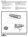
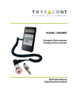
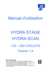
Manuale utente - User manual Bedienungsanleitung - Manuel pour l'utilisateur vedette 12 M CR vedette 12 M HR cod: VD 12 M CR - VD 12 M HR Vedette 12 M CR/HR ATTENZIONE: Prima di usare questi apparecchi, leggere attentamente le istruzioni che seguono. Spotlight srl non potrà essere ritenuta responsabile di danni derivanti dalla non osservanza di dette istruzioni. SAFETY WARNING: ACHTUNG: ATTENTION: Avant d’utiliser le projecteur, lisez attentivement les instructions suivantes. Spotlight srl ne pourra être tenu responsable pour les dommages resultants de la non-observation de ces instructions-ci. Before using this product, read the present instructions carefully. Spotlight srl will not be responsible for damage resulting from instructions not being followed. Vor Inbetriebnahme zuerst die folgenden Anweisungen sorgfältig lesen. Bei nicht Beachtung übernimmt Spotlight srl keinerlei Haftung. 2 Vedette 12 M CR/HR DESCRIZIONE DEL FARO INSTALLAZIONE Riferendoci alle immagini II faro viene normalmente usato montato su un cavalletto. ① Corpo lanterna ② Sportello superiore ③ Staffa per montaggio su cavalletto ④ Pomello per regolazione calotta ⑤ Manopole per regolazione lenti ⑥ Manopole per regolazione ghigliottine ⑦ Manopola per rotazione set ghigliottine ⑧ Leva per controllo diaframma ⑨ Viti per regolazione centraggio lampada ⑩ Cavo di collegamento al ballast ⑪Contaore ⑫ Ballast ATTENZIONE! NON INSTALLARE IL FARO SU SUPERFICI NORMALMENTE INFIAMMABILI E MANTENERE LA DISTANZA MINIMA INDICATA SULLA TARGHETTA. Estrarre il faro dall’imballaggio e montarlo su di un cavalletto, quindi montare il cambiacolori se previsto. Aprire ora lo sportello superiore ② per accedere allo zoccolo portalampada. Far avanzare completamente la calotta a specchio tramite il pomello ④ onde permettere il montaggio della lampada. Montare la lampada prevista, tenendo presente che questa può essere danneggiata dal contatto della pelle o con altri elementi unti e/o sporchi di grasso. Riportare la calotta in posizione e chiudere lo sportello superiore. Collegare il faro (tramite il cavo già montato) all’idoneo alimentatore e collegare quest’ultimo alla rete di alimentazione rispettando le normative di sicurezza GENERALITÀ Faro Seguipersone per lampade a ioduri metallici tipo bispina (Single Ended). Alimentazione a 220 V-50 Hz tramite apposito ballast. Possibilità di montaggio anteriore di cambia colori. Il faro in vostro possesso risponde alle Direttive CEE applicate: 73/23 e 89/336 in quanto conforme alle norme EN 60598-1 ed EN 60598-2-17. CAMBIO DELLA LAMPADA ATTENZIONE! SCOLLEGARE SEMPRE IL FARO PRIMA DI APRIRLO O SMONTARLO. La targhetta che è localizzata sulla fiancata del faro, contiene le seguenti informazioni: • modello • massima tensione di alimentazione in V • massima potenza della lampada in W • indice di protezione IP • massima temperatura ambiente ammissibile in °C • massima temperatura del corpo del faro in °C • distanza minima da ogni superficie infiammabile • informazioni per riconoscere la posizione 0°del faro: quando la punta della freccia è rivolta verso l’alto • angolo massimo di inclinazione verso l’alto e verso il basso. Questi limiti, imposti dal costruttore della lampada, non devono essere superati pena una riduzione della vita utile della lampada o il deterioramento del faro. Ricordarsi che questi fari funzionano con lampade a ioduri metallici che emettono raggi UV e che possono scoppiare a caldo. Attendere quindi che la lampada sia fredda prima di sostituirla. Utilizzare solo lampade del modello e della potenza descritta. Sul faro è presente anche un contaore ⑪ a cui bisogna far riferimento per controllare il tempo di effettivo funzionamento di ciascuna lampada. Occorre, infatti, sostituire la lampada, anche se funzionante, quando ha raggiunto la vita massi ma prevista dal costruttore. CENTRATURA DELLA LAMPADA Effettuare la regolazione a lampada calda, cioé almeno 4/5 minuti dopo l’accensione. E’ possibile centrare la lampada agendo sulle viti di regolazione ⑨. La regolazione va effettuata controllando l’uniformità dello spot luminoso agendo con il pomello ④ e regolando nel contempo la posizione della lampada nello specchio. 3 Vedette 12 M CR/HR MESSA IN SERVIZIO sblocca il disco precedentemente inserito. PRIMA Dl RICHIUDERE IL CAMBIACOLORI ACCERTARSI CHE IL FARO SIA SPENTO. Accertarsi sempre che la tensione di rete sia quella indicata dalla targhetta fissata sul faro o sul rispettivo ballast prima di accendere l’apparecchio, e di aver rispettato il codice colore se avete montato o sostituito la spina di alimentazione (blu = neutro - giallo/verde = messa a terra) . Nel caso sia presente anche il cambiacolori, accertarsi che questo sia stato aperto. Per accendere il faro, inserire l’interruttore genera le magnetotermico di sicurezza sull’alimentatore e premere l’apposito pulsante d’innesco per una durata massima di circa 2 secondi. MANUTENZIONE Per una maggiore resa ottica si consiglia una periodica pulizia dalla lente e della calotta a specchio. Ricordarsi sempre di scollegare il faro dall’alimentazione elettrica e di lasciar raffreddare la lampada prima di effettuare qualsiasi intervento di pulizia o manutenzione. Per ragioni di sicurezza verificare (almeno una volta all’anno) il buon isolamento di tutte le parti elettriche e l’integrità delle parti meccaniche. ATTENZIONE! SPEGNERE SUBITO IL FARO NEL CASO VI FOSSE UNA LENTE ROTTA O MANCANTE. IN CASO Dl MANCATA ACCENSIONE, NON INSISTERE, MA SPEGNERE L’INTERRUTTORE GENERALE E RIPETERE TUTTA LA PROCEDURA DOPO CIRCA 10 SECONDI. ATTENZIONE ! DURANTE LA FASE D’INNESCO DELLA LAMPADA, NEL FARO È PRESENTE ALTA TENSIONE. RICICLAGGIO È normale e non pericoloso che l’accensione di un faro nuovo causi una leggera uscita di fumo dalle feritoie di aereazione; ciò è dovuto all’essicazione di probabili residui di olio di lavorazione e/o verniciatura e non è assolutamente pericoloso. Si consiglia di effettuare la prima accensione con una durata max. di 15 minuti al fine di permettere l’essicazione delle vernici e di favorire la durata dei componenti. Il prodotto deve essere riciclato o smaltito secondo la direttiva 2002/96/CE PUNTAMENTO L’apertura o chiusura del fascio luminoso (zoom e messa a fuoco) è ottenibile tramite lo spostamento coordinato delle due manopole ⑤ poste sulla fiancata destra del faro che comandano lo spostamento dei carrelli portalenti. La larghezza dello spot luminoso è ulteriormente controllabile tramite la leva ⑧ che controlla l’apertura/ chiusura del diaframma (con possibilità anche di chiusura totale). Con le manopole ⑥ si può effettuare il taglio di parte dello spot luminoso, mentre con la manopola ⑦ si può ottenere la rotazione di tutto il sistema portaghigliottine. Nel caso sia presente anche il cambiacolori, si può inserire il disco porta-gelatina del colore prescelto agendo sulla levetta del rispettivo colore. Tenere presente che l’inserimento di un ulteriore disco 4 Vedette 12 M CR/HR DESCRIPTION OF THE LUMINAIRE Remove the luminaire from the package and mount it on the support, then mount the colour changer, if foreseen. Now open the top door ② to access the lamp-holder base. With the aid of knob ④, make the mirror head advance completely in order to install the lamp. Mount the relevant lamp, bearing in mind that this can be damaged by contact with skin or with other greasy and/or oily substances. Return the mirror head to its previous position and shut the top door. Connect the Followspot (by means of the cord already mounted) to the ballast and connect the latter to the mains supply in compliance with the safety standards in force. Refer to pictures ①Luminaire body ②Top door ③Stand mounting yoke ④Knob for adjusting mirror head ⑤Lever for adjusting lens ⑥Lever for shutters adjusting ⑦Lever handle for shutter-set rotation ⑧Diaphragm control lever ⑨ Lamp position adjustment screws ⑩Ballast connection cable ⑪Time meter ⑫Ballast CHANGING THE LAMP WARNING! ALWAYS DISCONNECT THE LUMINAIRE BEFORE OPENING OR DISMANTLING. GENERAL Followspot fitted with single-ended metal halide lamp. 220V-50 Hz power supply by means of relevant ballast. It can be mounted with colour changer on the front. The luminaire you have bought conforms to EEC Directives 73/23 and 89/336 as it complies with standards EN 60598-1 and EN 60598-2-17. The label located on the side of the luminaire contains the following information: • model • maximum supply voltage in (V) • maximum power of the luminaire (W) • the index of IP protection • maximum admitted temperature of the environment (°C) • maximum temperature of the luminaire body in °C • minimum distance from any inflammable surface • information to find the 0° position of the luminaire: when the tip of the arrow points upwards • maximum angle of inclination upwards and downwards. These limits, imposed by the lamp manufacturer, should not be exceeded as they would reduce the luminaire’s useful life or lead to its deterioration. Remember that these Followspots operate with metal halide lamps that emit UV radiation, and which can explode when hot. Therefore, it is strongly advisable to wait for the lamp to cool before replacing it. Only use lamps of the power and model described. The luminaire is also provided with a time meter ⑪ which must be used to check the actual running time of each lamp. In fact, once the maximum lamp life estimated by the lamp manufacturer is reached, the lamp must be replaced even if it is still working. CONTINUING TO USE THE LAMP AFTER EXPIRY OF ITS NOMINAL LIFE GREATLY INCREASES THE RISK OF IT TO EXPLODE. LAMP CALIBRATION Calibrate the lamp when it is hot, that is at least 4/5 minutes after ignition. Lamp calibration can be carried out by using the adjusting screws ⑨. The lamp must be calibrated by checking that the luminous spot is uniform, but using knob ④ and simultaneously adjusting the lamp position in the mirror. OPERATION INSTALLATION Always check that the mains voltage corresponds to the one indicated on the label affixed on the luminaire or on the relevant ballast before switching on the luminaire, and that the colour code has been conformed to if you have mounted or replaced the power supply plug. The luminaire is usually mounted on a stand. WARNING! DO NOT INSTALL THE LUMINAIRE ON FLAMMABLE SURFACES, AND MAINTAIN THE MINIMUM DISTANCE INDICATED ON THE LABEL. 5 Vedette 12 M CR/HR RECYCLING (blue = neutral; yellow/green = earthing). If a colour changer is fitted, be sure that this is open. To ignite the luminaire, switch on the general safety circuit breaker of the ballast and press the relevant ON button for no longer than 2 seconds. IF THE LUMINAIRE IS NOT IGNITED, DO NOT INSIST. SWITCH OFF THE GENERAL SWITCH AND REPEAT THE WHOLE PROCEDURE AFTER ABOUT 10 SECONDS. The product must be recycled or disposed of, according to Directive 2002/96/CE. WARNING! HIGH VOLTAGE IS PRESENT IN THE LUMINAIRE DURING THE LAMP IGNITION PHASE. When a new luminaire is switched on, a slight emission of smoke from the ventilation openings is absolutely normal and not dangerous. We recommend the first ignition to last no longer than 15 minutes max. so as to allow the paint to dry and to favour extended component life. FOCUS AND REGULATION The widening or narrowing of the luminous beam (zoom and focus) is carried out by co-ordinated shifting of the two levers ⑤ on the right side of the luminaire which control motions of the lenses’ guides. The width of the luminous beam can be controlled further by means of lever ⑧, which controls shutter opening/closure (allowing for total blacking out). By means of levers ⑥ part of the luminous beam can be blacked out, while the entire shutter-blade holding unit can be rotated by means of lever ⑦. If the colour changer is mounted, the gelatine-frame of the selected colour can also be inserted by operating on the relevant colour lever. Remember that the introduction of another filter unlocks the filter previously inserted. MAKE SURE THE LUMINAIRE IS SWITCHED OFF BEFORE RECLOSING THE COLOUR CHANGER MAINTENANCE For utmost optical performance, the lens and mirror head must be regularly cleaned. Always remember to disconnect the luminaire from the mains and allow the lamp to cool before proceeding to any cleaning or servicing. For safety reasons check (at least once yearly) that all the electrical parts are well insulated and that the mechanical parts are intact. WARNING! SWITCH OFF THE LUMINAIRE IMMEDIATELY IF A LENS IS BROKEN OR MISSING. 6 Vedette 12 M CR/HR BESCHREIBUNG DES STRAHLERS Den Strahler aus der Packung nehmen und auf ein Stativ montieren. Anschließend die Farbwchselvorrichtung anbringen, wenn diese vorgesehen ist. Nun die obere Offnung ② öffnen, um die Lampenfassung erreichen zu können. Der Reflektor mit Hilfe des Knopfes ④ ganz nach vorn schieben, damit die Lampe eingesetzt werden kann. Dann die Lampe einstecken, wobei daran gedacht werden muß, daß diese durch die Berührung mit der Haut oder andere schmutzige oder fette Elemente beschädigt werden kann. Den Reflektor wieder zurückschieben und die obere Öffnung ② schließen. Den Strahler mittels des bereits montierten Kabels mit dem dafür vorgesehenen Ballast verbinden und dieses an das Stromnetz anschließen. Beachten Sie bitte die entsprechenden Sicherheitsvorschriften. Bezug: siehe Abbildungen. ①Scheinwerfergehäuse ②Öffnung Leuchtmittelwechsel ③Bügel für Montage auf Stativ ④Drehknopf Leuchtmittelwechsel - Reflektor Regulierung ⑤Schellverriegler Zoomlinsen Fokussierung ⑥Blendenschieber 4x ⑦Drehbare Blendenschieber Ebene - Blockierung ⑧Iris Einstellung ⑨Schrauben zur Einstellung der Lampenzentrierung ⑩Verbindungskabel zum Ballast ⑪Stundenzähler ⑫Ballast ALLGEMEINES LAMPENWECHSEL Beweglicher Richtungsstrahler für Jodidmetalldampflampen, Zweisteckertyp (Single Ended). Versorgung 220 V-50 Hz durch Ballast. Es besteht die Möglichkeit, auf der Vorderseite eine Farbwechselvorrichtung zu montieren. Ihr Strahler entspricht den Anforderungen der Richtlinien 73/23/ CEE und 89/336/CEE, da er konform zu den Normen EN 60598 - 1 und EN 60598-2-17 ist. Das Kennschild auf der Strahlerrückseite enthält die folgenden Informationen: • Modell • Maximale Zufuhrspannung in V • Maximalleistung der Lampe in W • IP-Schutzindex • Maximal gestattete Raumtemperatur in °C • Maximale Strahlerkörpertemperatur in °C • Mindestabstand von brennbaren Oberflächen • Informationen zur Erkennung der 0°-Stellung des Strahlers: wenn die Pfeilspitze nach oben zeigt • Maximaler Neigungswinkel nach unten und oben. Diese Grenzen, die vom Lampenhersteller vorgegeben werden, dürfen nicht überschritten werden; andernfalls verkürzt sich die Lebensdauer der Lampe, oder der Strahler wird beschädigt. Ziehen Sie aus Sicherheitsgründen stets den Netzstecker, bevor Sie den Apparat öffnen und die Lampe wechseln. Denken Sie bitte daran, daß dieser Strahler Jodidmetalldampflampen enthält, die UVStrahlen abgeben und in warmem Zustand explodieren können. Es ist also notwendig, die vollkommene Abkühlung der Lampe abzuwarten, bevor diese gewechselt wird.Es dürfen nur die Lampen des hier beschriebenen Modells und der angegebenen Leistung benutzt werden. Auf dem Strahler befindet sich auch ein Stundenzähler ⑪, auf den man sich beziehen muß, um die effektive Nutzzeit jeder Lampe zu kontrollieren. Es ist in der Tat notwendig, die Lampe auch dann zu wechseln, wenn sie noch funktionsfähig ist, aber die vom Hersteller angegebene Maximalbetriebszeit erreicht hat. DIE ÜBER DIESE BETRIEBSZEIT HINAUSGEHENDE BENUTZUNG ERHÖHT DIE EXPLOSIONSGEFAHR DER LAMPE ERHEBLICH. LAMPENZENTRIERUNG Die Einstellung muß bei warmer Lampe ausgeführt werden, d.h. mindestens 4/5 Minuten nach dessen Zündung. Die Zentrierung geschieht durch die dafür vorgesehenen Schrauben ⑨. Bei der Einstellung muß auf eine einheitliche Verbreitung des Lichtstrahls geachtet werden, indem man den Knauf ④ betätigt und gleichzeitig die Position der Lampe im Spiegel reguliert. INSTALLATION Der Strahler wird normalerweise auf ein Stativ montiert angewandt. ACHTUNG! DER STRAHLER DARF NICHT AUF BRENNBAREN OBERFLACHEN INSTALLIERT WERDEN. 7 Vedette 12 M CR/HR INBETRIEBNAHME indem man den Hebel der gewünschten Farbe betätigt. Achten Sie darauf, daß die Einführung einer weiteren Scheibe die vorher benutzte Scheibe entsperrt. BEVOR DIE FARBWECHSELVORRICHTUNG WIEDER GESCHLOSSEN WIRD, MUSS SICHERGESTELLT SEIN, DASS DER STRAHLER AUSGESCHALTET IST. Vor Einschaltung des Gerätes muß immer darauf geachtet werden, daß die auf dem Kennschild angegebene Spannung mit der des Stromnetzes übereinstimmt und daß die Farbkodierung korrekt ist, wenn der Verbindungsstecker gewechselt wurde (blau=neutral, gelb/grün=Erdung). Das Kennschild befindet sich auf dem Strahler oder dem entsprechenden Ballast. Falls auch eine Farbwechselvorrichtung vorhanden sein sollte, muß man sich davon überzeugen, daß diese vorher geöffnet wurde. Um den Strahler einzuschalten drücken Sie den Automat auf dem Speisegerät und betätigen Sie dann ca. 2 Sekunden lang den Zündungsknopf. FALLS KEINE ZÜNDUNG STATTFINDEN SOLLTE, BESTEHEN SIE NICHT WEITER DARAUF; STELLEN SIE DEN HAUPTSCHALTER AUS UND WIEDERHOLEN SIE NACH CA. 10 SEKUNDEN DEN GANZEN VORGANG NOCH EINMAL. WARTUNG Für eine maximale optische Leistung sollten die Linse und die Spiegelkalotte regelmäßig gesäubert werden. Denken Sie stets daran, vor jedem Sauberungsoder Wartungseingriff den Netzstecker zu ziehen und die Lampe vollkommen abkühlen zu lassen. Aus Sicherheitsgründen sollte die Isolierung aller elektrischen Teile und die Integrität sämtlicher mechanischer Elemente mindestens einmal im Jahr geprüft werden. SEHR WICHTIG! BEI FEHLEN ODER BRUCH EINER LINSE DEN STRAHLER SOFORT AUSSCHALTEN!. VORSICHT! WÄHREND DER ZÜNDUNG BESTEHT IM STRAHLER HOCHSPANNUNG! ENTSORGUNG Das Produkt muss entsprechend den Richtlinien 2002/96/CE wiederverwendet oder entsorgt werden. Es ist vollkommen normal und ungefährlich, wenn bei Zündung einer neuen Lampe etwas Rauch aus den Belüftungsschlitzen tritt. Das beruht auf der Trocknung von kleinen Öl- und/oder Lackierungsrückständen, die sich bei der Verarbeitung bilden können, aber absolut ungefährlich sind. Es wird empfohlen, die erste Zündung einer neuen Lampe auf höchstens 15 Minuten zu beschränken, damit die eventuellen Rückstände austrocknen können und die Lebensdauer der Komponenten dadurch erhöht wird. AUSRICHTUNG Die Weitung oder Einengung des Lichtstrahls (Zoom oder Scharfeinstellung) kann durch koordiniertes Verschieben der beiden Knäufe ⑤ erreicht werden, die auf der rechten Seite des Strahlers angebracht sind und die Verschiebung der Linseneinheit steuern. Die Breite des Lichtstrahls kann außerdem durch den Hebel ⑧ geschehen, der dieOffnung / Schließung der Blende steuert (und diese auch vollkommen schließen kann). Mit dem Knauf ⑥ kann man eine teilweise Abdeckung des Lichtstrahls erzeugen, während der Knauf ⑦ zur Drehung des gesamten Schutzschirmsystems dient. Falls eine Farbwechselvorrichtung existiert, kann die gewählte Farbgelatinenscheibe eingeführt werden, 8 Vedette 12 M CR/HR DESCRIPTION DU PROJECTEUR INSTALLATION D’après les dessins Le projecteur est normalement utilisé monté sur un chevalet. ATTENTION! NE PAS POSER LE PROJECTEUR SUR DES SURFACES NORMALEMENT INFLAMMABLES ET MAINTENIR LA DISTANCE MINIMUM INDIQUEE SUR L’ETIQUETTE. Sortir le projecteur de l’emballage et le monter sur un chevalet. Monter ensuite le changeur de couleurs si celui-ci est prévu. Ouvrir le clapet supérieur ② pour accéder au culot de la douille. Faire avancer complètement la calotte à miroir avec le pommeau ④ pour permettre le montage de la lampe. Monter la lampe prévue, en tenant compte que celle-ci peut être endommagée au contact de la peau ou d’autres éléments gras et/ou recouverts de graisse. Ramener la calotte en position et fermer le clapet supérieur. Relier le projecteur (avec le câble déjà monté) à l’alimentateur adapté et relier ce dernier au réseau d’alimentation en respectant les réglementations de sécurité. ① Corps lanterne ② Clapet supérieur ③ Etrier pour montage sur chevalet ④ Pommeau pour réglage calotte ⑤Poignées pour réglage lentilles ⑥Poignées pour réglage couteaux ⑦Poignées pour réglage bloc couteaux ⑧ Levier pour contrôle diaphragme ⑨ Vis pour réglage centrage lampes ⑩ Câble de liaison au ballast ⑪ Compte-heures ⑫ Ballast GENERALITES Projecteur directif pour lampes à iodures métalliques du type à deux fiches (Single Ended). Alimentation à 220 V-50 Hz avec ballast approprié. Possibilité de montage antérieur de changeur de couleurs. Le projecteur en votre possession répond aux Directives CEE appliquées 73/23 et 89/336 ellesmêmes conformes aux normes EN 60598-1 et EN 60598-2-17. L’étiquette figurant sur le côté du projecteur contient les informations suivantes: CHANGEMENT DE LA LAMPE ATTENTION! DEBRANCHER TOUJOURS LE PROJECTEUR AVANT DE L’OUVRIR OU DE LE DEMONTER. Se rappeler que ces projecteurs fonctionnent avec des lampes à iodures métalliques qui émettent des rayons UV et qui peuvent exploser à la chaleur. Attendre que la lampe soit froide avant de la remplacer. N’utiliser que des lampes du modèle et de la puissance décrits. Il y a aussi sur le projecteur un compte-heures ⑪ auquel il faut faire référence pour contrôler le temps de fonctionnement effectif de chaque lampe. Il faut en effet remplacer la lampe, même si elle fonctionne, quand elle a atteint la durée maximum prévue par le constructeur. LE FONCTIONNEMENT AU-DELA DE LA DUREE NOMINALE AUGMENTE BEAUCOUP LES RISQUES D’EXPLOSION DE LA LAMPE. • • • • • • • • modèle tension maximum d’alimentation en V puissance maximum de la lampe en W indice de protection IP température ambiante maximale admissible en °C température maximale du corps du projecteur en °C distance minimum de toute surface inflammable informations permettant de reconnaître la position 0° du projecteur: quand la pointe de la flèche est tournée vers le haut • angle maximum d’inclinaison vers le haut et vers le bas. Ces limites, imposées par le constructeur de la lampe, ne doivent pas être dépassées sous peine de réduire la durée de vie de la lampe ou de détériorer le projecteur. CENTRAGE DE LA LAMPE Effectuer le réglage quand la lampe est chaude, c’està-dire au moins 4/5 minutes après l’allumage. Il est possible de centrer la lampe en actionnant les vis de réglage ⑨. Le réglage doit être effectué en contrôlant 9 Vedette 12 M CR/HR l’uniformité du spot lumineux en actionnant le pommeau ④ et en réglant en même temps la position de la lampe dans le miroir on peut insérer le disque porte-gélatines de la couleur choisie en actionnant le levier de la couleur respective. Ne pas oublier que l’introduction d’un autre disque débloque le disque introduit précédemment. AVANT DE REFERMER LE CHANGEUR DE COULEURS, S’ASSURER QUE LE PROJECTEUR EST ETEINT. MISE EN SERVICE S’assurer toujours que la tension de réseau est celle qui est indiquée sur l’étiquette fixée sur le projecteur ou sur le ballast respectif avant d’allumer l’appareil, et d’avoir respecté le code de couleur si vous avez monté ou remplacé la fiche d’alimentation. (bleu = neutre - jaune/vert = mise à la terre). S’il y a aussi le changeur de couleurs, s’assurer que celui-ci a été ouvert. Pour allumer le projecteur, introduire l’interrupteur général magnothermique de sécurité sur l’alimentateur et appuyer sur le bouton de déclenchement pendant 2 secondes maximum environ. EN CAS DE NON-ALLUMAGE, NE PAS INSISTER, MAIS ETEINDRE L’INTERRUPTEUR GENERAL ET REPETER TOUTE LA PROCEDURE APRES 10 SECONDES ENVIRON. ATTENTION! PENDANT LA PHASE DE DECLENCHEMENT DE LA LAMPE, IL Y A DE LA HAUTE TENSION DANS LE PROJECTEUR. Il est normal et non dangereux que l’allumage d’un nouveau projecteur cause une légère perte de fumée des fentes d’aération: ceci est dû à la dessiccation de probables résidus d’huile d’usinage et/ou vernissage et ce n’est absolument pas dangereux. On conseille d’effectuer le premier allumage avec une durée maximum de 15 minutes afin de permettre la dessiccation des vernis et de favoriser la durée des composants. ENTRETIEN Pour un rendement optimal maximum du projecteur, on conseille de nettoyer périodiquement la lentille et la calotte à miroir. Se rappeler toujours de débrancher la projecteur de l’alimentation électrique et de laisser refroidir la lampe avant d’effectuer toute intervention de nettoyage ou d’entretien. Pour des raisons de sécurité, vérifier (au moins une fois par an) le bon isolement de toutes les parties électriques et l’intégralité des parties mécaniques. ATTENTION! ETEINDRE IMMEDIATEMENT LE PROJECTEUR S’IL Y A UNE LENTILLE CASSEE OU MANQUANTE. RECYCLAGE Le produit doit etre recyclé, ou éliminé suivant les directives 2002/96/CE POINTAGE L’ouverture ou la fermeture du faisceau lumineux (zoom et mise à point) peut s’obtenir avec le déplacement coordonné des deux poignées ⑤ placés sur le côté droit du projecteur qui commandent le déplacement des chariots porte-lentilles. La largeur du spot lumineux peut encore être contrôlée à l’aide du levier ⑧ qui contrôle l’ouverture/fermeture du diaphragme (avec possibilité de fermeture totale). Avec les poignées ⑥, on peut effectuer la coupure d’une partie du spot lumineux, tandis qu’avec le poignées ⑦, on peut obtenir la rotation de tout le système porte-couteaux. S’il y a aussi le changeur de couleurs, 10 Vedette 12 M CR/HR Dimensioni e peso - Dimensions and weight - Masse und Gewicht - Dimensions et poids 1124 309 200 428 200 VD 12 M CR Kg. 17,3 - VD 12 M HR Kg. 18,9 256 204 200 BALLAST Kg. 14,8 Lampade - Lamps - Leuchtmitteltypen - Lampes Codice int. - Int’l code Kodex - Code W VD 12 M CR MSR 1200 1200 VD 12 M HR MSR 1200 HR 1200 11 lm K t(h) G 22 110000 5600 800 G 38 110000 5600 800 Vedette 12 M CR/HR certified quality management system ISO 9001 : 2008 Spotlight s.r.l. Via Sardegna 3 20098 S. Giuliano Milanese Milano - Italy Tel. +39.02.98830.1 Fax +39.02.98830.22 E-mai: [email protected] www.spotlight.it