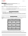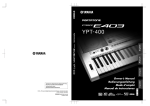
1
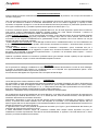
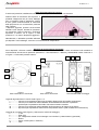
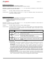
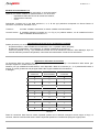
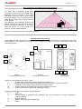
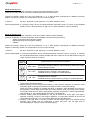
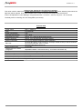
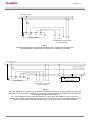
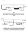
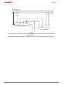
made in E.U.
JUNIOR
MANAGER
MANUALE UTENTE
USER’S HANDBOOK
• italiano
• english
NEON LINE Technical service: mail [email protected]
B.LM001 rev. 0
NEON LINE Technical service: mail [email protected]
B.LM001 rev. 0
ISTRUZIONI JUNIOR MANAGER
italiano
Descrizione e funzionamento
Svolge la duplice funzione di mantenimento di luce costante e di rilevatore di presenza, con lo scopo di minimizzare il
consumo energetico.
Una volta impostato il livello di luce desiderato, il Junior Manager rileva la luce esterna e regola la luce delle lampade
in modo da mantenere costante la luminosità dell'ambiente. Se la luce esterna raggiunge (o supera) il livello
impostato, le lampade si spengono. In caso di elevate riflessioni luminose (ad esempio in presenza di pavimenti molto
scuri oppure soffitti bianchi), è possibile impostare diversi gradi di correzione (da 1 a 4).
Il sensore di presenza produce l’innalzamento graduale della luce, fino al livello impostato, quando rileva movimento
nella stanza; produce l’abbassamento altrettanto graduale quando non viene rilevato movimento. Il sensore di
presenza può funzionare in tre diverse modalità, una alternativa all’altra:
Æ Nella modalità “automatica”, se non viene rilevato movimento, Junior Manager riduce la luminosità delle lampade
dopo un periodo di attesa (lagging time) impostabile e le spegne dopo altri 10 minuti. Quando viene rilevato un
movimento, le luci vengono immediatamente e gradualmente accese, ammesso che la luce esterna non sia già
superiore al livello di luminosità impostato.
Æ Nella modalità “semi-automatica”, Junior Manager funziona come in modalità automatica, con l’unica differenza che
le luci NON si riaccendono, neppure quando viene rilevato nuovamente movimento. L’accensione deve avvenire in
modo manuale.
Æ Nella modalità “disattivo”, il sensore di presenza è disattivato: il dispositivo, quindi, funzionerà solo per il
mantenimento della luce costante. Si suggerisce, in questo caso, di inserire nel sistema un interruttore luminoso, così
da evitare che le lampade si accendano inopportunamente – in periodi in cui dovrebbero essere spente – a motivo
dell’abbassamento della luce esterna.
Optional: è possibile utilizzare un interruttore / pulsante esterno (per esempio montato a parete) sia per impostare il
livello di luce costante, sia per il controllo manuale delle lampade connesse.
Avvertenze
Per le operazioni di cablaggio, installazione e manutenzione, sconnettere l’alimentazione a monte di Junior Manager.
Il pericolo di potenziale choc elettrico va considerato anche se le lampade sono apparentemente spente. Junior
Manager deve essere installato da personale qualificato.
Il funzionamento dell’apparecchio è garantito solo nel rispetto dei dati di targa.
Installazione
Junior Manager deve essere installato a soffitto.
Per minimizzare il rischio di danneggiamento durante l’installazione, la staffa di fissaggio ed il blocco funzionale sono
separati. Fissare la staffa di sostegno al soffitto con apposite viti, quindi collegare l’alimentazione ed il carico (vedere
schemi di cablaggio contenuti nelle Figure 4, 5, 6, 7, 8 del presente manuale). Infine, posizionare il blocco funzionale –
dopo aver definito la modalità di funzionamento (vedere relativo paragrafo).
Attenzione: l’installatore deve provvedere alla protezione della linea, tramite fusibile.
Per la definizione del punto di installazione del Junior Manager, si consideri che le lenti del sensore di presenza sono
dimensionate per soffitti di altezza tra 2,5 e 3,0 m. In stanze più alte, l’area monitorata aumenta, ma la precisione di
rilevazione del sensore di movimento diminuisce.
Posizionare il dispositivo in modo che le lenti del sensore puntino sull’area da monitorare (per esempio, il posto di
lavoro). Il sensore deve essere installato vicino alle lampade da controllare e non direttamente esposto alla luce
esterna oppure alla luce di altre lampade: la luminosità dell’ambiente viene infatti rilevata indirettamente tramite la luce
riflessa sul pavimento (o sul tavolo di lavoro).
E’ opportuno fare in modo che il pulsante di regolazione luminosità (3 in Figura 1) punti direttamente alla finestra, per
ottimizzare la rilevazione del sensore luminoso.
Il valore dell’intensità luminosa “target” da mantenere costante deve sempre essere impostato nel punto di
installazione. Durante l’impostazione del livello di luminosità desiderato, è opportuno che nella stanza non vi siano
persone, per evitare di falsare la misurazione.
NEON LINE Technical service: mail [email protected]
B.LM001 rev. 0
Area di monitoraggio del sensore
Il sensore di presenza, installato ad un'altezza di 3 m, copre un'area di circa 7 m di diametro.
Qualora l'area da monitorare sia superiore, è
possibile collegare tra loro più Junior Manager
(per un massimo di altri 5 dispositivi): ognuno
di essi gestirà autonomamente la luminosità
della propria area, ma la rilevazione presenza
sarà unificata.
I dispositivi aggiuntivi possono anche essere
utilizzati come semplici rilevatori di presenza,
per aumentare l’area monitorata: è sufficiente
impostare il trimmer 4a in Figura 2 nella
posizione “F” su ciascun dispositivo aggiuntivo.
Naturalmente, è altrettanto possibile utilizzare
più dispositivi Junior Manager, ciascuno con funzionamento indipendente.
Modalità di funzionamento disponibili
Sono disponibili 3 diverse modalità di funzionamento: la differenza tra di esse risiede unicamente sulla modalità di
funzionamento del sensore di presenza (automatica – semi-automatica – disattivo), selezionabile tramite il trimmer 2
in Figura 1 e l’eventuale pulsante esterno.
5
6
7
4b
4a
1
3
2
8
Figura 1
Vista frontale blocco funzionale
Figura 2
Retro blocco funzionale
9
10
Figura 3
Vista frontale staffa di fissaggio
Legenda degli elementi di controllo nelle Figure 1 e 2:
1 .................trimmer per la regolazione del tempo di ritardo (lagging time) prima dello spegnimento
2 .................trimmer per la selezione della modalità di funzionamento del sensore di presenza
3 .................pulsante per l’impostazione del livello di luce da mantenere costante
4a ...............trimmer per la selezione della modalità di funzionamento e del fattore di correzione
4b ...............dip-switch per impostazioni delle funzioni del pulsante esterno (vedi modalità di funzionamento)
Legenda dei connettori nella Figura 3 (vedere anche schemi di cablaggio):
5 .................1-10V
6 .................Earth (0V)
7 .................per collegamento ad altri Junior Manager o a interruttori / pulsanti esterni (opzionale)
8 .................Neutro
9 .................Switch contact (fase, in tensione)
10 ...............Fase
NEON LINE Technical service: mail [email protected]
B.LM001 rev. 0
Modalità di funzionamento n.1
Possibilità di selezione tra modalità “automatica” e “disattivo”.
Optional: il sensore di presenza può essere disattivato da un interruttore esterno.
Posizionare il trimmer 4a in una delle posizioni 0, 1, 2, 3. Ad ogni posizione corrisponde un diverso fattore di
correzione: la posizione “standard” è la numero 2.
Trimmer 2:
a sinistra: modalità “automatica”; a destra: modalità “disattivo”
Controllo remoto: E’ possibile collegare (connettori 6 e 7 in Fig. 3) un interruttore esterno. Alla posizione ON,
corrisponde la modalità “disattivo”.
Modalità di funzionamento n.2
Possibilità di selezione tra modalità “automatica” e una funzione senza rilevazione presenza.
Optional: può essere installato un pulsante esterno, con le funzioni:
- impostazione del livello di luce da mantenere costante;
- dimmerazione manuale;
- ON/OFF.
Posizionare il trimmer 4a in una delle posizioni 4, 5, 6, 7. Ad ogni posizione corrisponde un diverso fattore di
correzione: la posizione “standard” è la numero 6.
Trimmer 2:
a sinistra: modalità “automatica”; a destra: modalità “disattivo”
Controllo remoto: E’ possibile collegare (connettori 6 e 7 in Fig. 3) un pulsante esterno, con le funzioni sotto elencate.
Si consideri poi che è possibile disattivare alcune funzionalità, agendo sul dip-switch 4b (vedi
Figura 2), nei seguenti termini:
Posizione
dip-switch 4b
Funzioni attive sul pulsante esterno
OFF – OFF:
Tutte le funzioni sono attive: ON/OFF; dimmerazione; memoria
del livello di luce costante
ON – OFF:
Funzioni attive: ON/OFF; dimmerazione
Funzioni disattive: memoria del livello di luce costante
ON – ON:
Funzioni attive: ON/OFF
Funzioni disattive: dimmerazione, memoria del livello di luce
costante
Tabella 1
Utilizzo pulsante:
Æ Dimmerazione. Tenere premuto il pulsante (> 400 ms) per variare l’intensità luminosa. Arrivati al
minimo oppure al massimo, premere nuovamente il pulsante per invertire il senso di
dimmerazione.
Se la funzione “memoria del livello di luce costante” è disattiva, il dispositivo non mantiene la
luce costante, ma viene unicamente gestito in modo manuale. Questo stato, comunque, dura
fino a quando il sistema viene spento manualmente o per assenza di rilevazione di movimento.
Accendendo nuovamente il sistema, esso manterrà la luminosità precedentemente impostata.
Æ ON/OFF. Premere il pulsante (< 400 ms) per accendere o spegnere le luci. Se la luce viene
spenta mentre il sensore di presenza rileva un movimento, essa rimane spenta e può essere
riaccesa solo manualmente oppure nel caso venga rilevato movimento dopo il tempo di ritardo
(delay time) impostato.
Æ Impostazione del livello di luce da mantenere costante. Impostare il livello desiderato tramite
dimmerazione (come già descritto), quindi premere due volte il pulsante per memorizzare tale
livello. La memorizzazione è confermata da un lampeggio delle lampade collegate.
NEON LINE Technical service: mail [email protected]
B.LM001 rev. 0
Modalità di funzionamento n.3
Possibilità di selezione tra modalità “automatica” e “semi-automatica”.
Optional: può essere installato un pulsante esterno, con le funzioni:
- impostazione del livello di luce da mantenere costante;
- dimmerazione manuale;
- on/off.
Posizionare il trimmer 4a in una delle posizioni 8, 9, A, B. Ad ogni posizione corrisponde un diverso fattore di
correzione: la posizione “standard” è la A.
Trimmer 2:
a sinistra: modalità “automatica”; a destra: modalità “semi-automatica”.
Controllo remoto: E’ possibile collegare (connettori 6 e 7 in Fig. 3) un pulsante esterno, con le medesime funzioni
della “modalità di funzionamento n.2”.
Impostazione del livello di luce da mantenere costante
Questo parametro può essere impostato:
- da pulsante esterno, nelle modalità di funzionamento n.2 e n.3 (vedere relativi paragrafi);
- direttamente sul dispositivo Junior Manager, in qualsiasi modalità di funzionamento.
Premere il pulsante 3 in Fig. 1 per selezionare il livello di luce da mantenere costante. Junior Manager, dopo 10
secondi dall’ultima pressione del pulsante, memorizza automaticamente il livello di luce selezionato.
Regolazione del fattore di correzione
La rilevazione della luce esterna può essere in qualche modo falsata dal tipo di arredamento della stanza (per
esempio: tappeti neri, soffitti bianchi, ecc.).
Pertanto, per ogni modalità di funzionamento, sono disponibili 4 fattori di correzione (0, I, II, III) selezionabili tramite il
trimmer 4a (come già descritto nei paragrafi relativi alle singole modalità di funzionamento.
In dettaglio:
Posizione
trimmer 4a
Modalità di
funzionamento
Fattore di
correzione
0
1
0
1
1
I
2
1
II
3
1
III
4
2
0
5
2
I
6
2
II
7
2
III
8
3
0
9
3
I
A
3
II
B
3
III
Tabella 2
Fattori di correzione bassi devono essere impostati quando le luci artificiali rimangono accese troppo a lungo; al
contrario, fattori di correzione alti devono essere impostati quando le luci artificiali si spengono troppo presto.
NEON LINE Technical service: mail [email protected]
B.LM001 rev. 0
Impostazione del tempo di attesa (lagging time) per l’abbassamento delle luci
Questo parametro, relativo al SOLO sensore di rilevazione presenza, viene impostato sul dispositivo Junior Manager
tramite il trimmer 1 in Fig. 1 e definisce il periodo (calcolato dall’ultima rilevazione di movimento) dopo il quale le luci
saranno abbassate. Il valore impostabile può variare da 1 a 30 minuti. Trascorso questo lasso di tempo, Junior
Manager spegnerà le luci dopo altri 10 minuti, non modificabili.
Il tempo di ritardo (delay time) per lo spegnimento derivante dal controllo di luce costante è di 10 minuti, non
modificabili.
Dati tecnici
Alimentazione
Fusibile
Potenza assorbita
Temperatura di
funzionamento
Livello luminoso regolabile
Angolo di rilevazione
Altezza di installazione
Carico massimo
Tempo di spegnimento
Tempo di attesa per
abbassamento luci in
assenza di movimento
Collegamenti in parallelo
Grado di protezione
Morsetti
Dimensioni (LxHxP)
Peso
230 V ~ 50/60 Hz
6 A (esterno)
2W
0°C ÷ 50°C
Circa 15 ÷ 1500 lux (sul dispositivo)
Circa 100° (sensore luminoso e rilevazione movimento)
2,5 ÷ 3,0 m (altezza ottimale per la rilevazione movimento)
50 lampade B-Lighting singole (o 25 doppie) della linea Contract
oppure 50 convertitori E-Neon con ingresso 1-10V
oppure 50 Dimmerbox Neon Line (15A)
10 minuti
impostabile da 1 a 30 min. (+ 10 min. per lo spegnimento)
Max 6 Junior Manager
IP20
Morsetti a vite per fili singoli o fili litz 0.3mm2 ÷ 1.5mm2
58.5 x 70.5 x 42 mm
approx. 150g
NEON LINE Technical service: mail [email protected]
B.LM001 rev. 0
JUNIOR MANAGER INSTRUCTIONS
English
Description
Junior Manager is suitable for constant-light control and presence detection in one unit. Its most important aim is to
minimize the energy costs.
Utilising a photosensor, the daylight is only supplemented by the amount of artificial light required to reach the preadjusted target of intensity. It means that when daylight reaches or exceeds the target intensity, the artificial light
switches off. In case of high reflections (i.e. black carpets, white ceiling, etc.), different correction degrees (4 steps) are
available.
The motion sensor adjusts the artificial light in a sliding manner to the target level when someone enters the room and
dims it again, in the same way, when the room has been left. After a delay time, the light is switched off. The motion
sensor works with three different motion detections, alternate to each other:
Æ “Automatic” mode: if no motion is detected, Junior Manager slowly reduces the light level after a set lagging time
and switches it off after 10 minutes. If a motion is recognized again, the lighting is immediately switched on, provided
the stored constant light level is not exceeded by the daylight level.
Æ “Semi-automatic” mode: similar to the automatic mode. After the lighting has been switched off, it would however
not automatically switch on after a motion recognized. It has to be switched on manually with a remote pushbutton.
Æ “No motion detection” mode: Junior Manager operates just as a constant-light control. The lighting would not switch
off, even after no motion is detected. It adjusts smoothlt to the daylight portion. An illuminated switch should be
incorporated in the circuit in order to avoid it being switched on again unintentionally when daylight diminishes.
Optional: a remote pushbutton allows the setting of nominal values as well as the manual control of the connected
lamps.
Warnings
Always disconnect the main supply before wiring, installation and maintenance operations: do not assume that the
uniti is off when lamps are not lighted. Junior Manager must be installed by qualified personnel only.
The device’s working is guaranteed only when plate data are respected.
Assembly instructions
Junior Manager is apt for the surface mounting on ceilings.
The mounting plate of the surface mounted device is fixed to the ceiling using screws and then wired to the mains and
to lamps or convertors or Dimmerbox (see wiring diagrams in Pictures 4, 5, 6, 7, 8). Then the functional part is simply
plugged on it, after having selected the different available functions (see following instructions). The mounting plate
and functional part are strictly separate. This decreases the danger of damage to the functional part during assembly.
Important! The installer must provide to the line’s protection using an appropriate fuse.
In defining the exact point of installation, consider that the optics of the motion sensor are designed for a ceiling height
of 2,5 m to 3,0 m. In higher rooms, the controlled area increases, but the density detection of the sensor diminishes.
Wherever possible, Junior Manager should be installed so that it points directly at the area to be covered (e.g.
working place). The sensor has to be installed near the controlled lamps and should not be exposed to direct exterior
daylight (e.g. close to a window) or to the light of separately controlled luminaries: the room brightness must be
detected indirectly by the light reflected from a table surface or from the floor.
It is best to wire Junior Manager in such a way that the intensity adjustment pushbutton (3 in Picture 1) points to the
direction of the window. This will correclty align the detection area of the photosensor with the room.
The actual light intensity value for the setting of the light level to be kept constant should always be picked up indirectly
by Junior Manager at the point of reference. During this operation, no person should be present directly under the
sensor, in order to avoid a falsification of the measured brightness value.
NEON LINE Technical service: mail [email protected]
B.LM001 rev. 0
Area of detection and extension of motion detection
The motion detection surveys an area of approx. 7 m in diameter, if the height of the room is 3 m.
If a larger area is supposed to be jointly
surveyed, the motion control of several Junior
Managers may be connected to each other
(max other 5 devices): each of them controls
its individual range in the constant light control
mode, but the motion control in done jointly for
the whole area.
The additional Junior Managers however can
also be used just as motion sensors in order to
extend the range of detection. In this case,
select the function “F” on the trimmer 4a in
Picture 2, for each additional device.
Of course, several devices may be individually employed.
Available operation functions
Three different modes of function are available: in each function the device works as a constant-light control with
motion detection. The difference is the function of the “change-over switch” (2 in Picture 1) and the function of the
remote adjustments.
5
6
7
4b
4a
1
3
2
8
Picture 1
Functional part: front view
Picture 2
Functional part: back view
9
10
Picture 3
Mounting plate
Legend of control elements in Pictures 1 and 2:
1 .................potentiometer for the setting of the lagging time until switch off
2 .................change-over switch for the selection between the 3 function mode of the motion sensor
3 .................pushbutton for the setting of the light level to be kept constant
4a ...............selector switch for the required function and the reflection correction
4b ...............switch for the setting of the remote pushbutton functions
Legend of terminals in Picture 3 (see also wiring diagrams):
5 .................1-10V
6 .................Earth (0V)
7 .................for the coupling of additional Junior Managers and for the connection of remote pushbuttons /
switches (optional)
8 .................Neutral conductor
9 .................Switch contact (phase, not voltage free)
10 ...............Phase
NEON LINE Technical service: mail [email protected]
B.LM001 rev. 0
Mode of function no. 1
Possibility to select between “automatic” mode and “no motion detection” mode.
Optional: the motion detection can also be deactivated with an external switch.
Position the selector switch 4a in one of the positions 0, 1, 2, 3. Each position corresponds to a different correction
degree: in particular, position n.2 corresponds to a room in the mid-range.
Trimmer 2:
left stop: “automatic” mode; right stop: “no motion detection” mode
Remote adjustments: A customary switch can be connected (between terminals 6 and 7 in Picture 3) and installed
inside the room. When the switch is “ON”, the “no motion detection” mode is activated.
Mode of function no.2
Possibility to select between “automatic” mode and a function without motion detection.
Optional: additionally, a remote pushbutton can be installed. It has the following functions:
- Setting of the light level to be kept constant;
- Manual dimming control (brighter / darker);
- ON/OFF.
Position the selector switch 4a in one of the positions 4, 5, 6, 7. Each position corresponds to a different correction
degree: in particular, position n.6 corresponds to a room in the mid-range.
Trimmer 2:
left stop: “automatic” mode; right stop: “no motion detection” mode
Remote adjustments: A customary pushbutton can be connected (between terminals 6 and 7 in Picture 3). It allows
the operations listed below. Please consider that some functions can be deactivated, using the
switch 4b (see Picture 2), as follows:
Position
switch 4b
Enabled functions of the remote pushbutton
OFF – OFF:
All functions enabled: ON/OFF; manual dimming; setting of the light
level to be kept constant
ON – OFF:
Enabled functions: ON/OFF; manual dimming
Disabled functions: storage of constant light level
ON – ON:
Enabled functions: ON/OFF
Disabled functions: manual dimming, storage of constant light level
Table 1
Usage of the remote pushbutton:
Æ Manual dimming. Continuously press the button (> 400 ms) to the maximum or minimum. Press
the button again to change the direction from Bright to Dark or from Dark to Bright.
When the function “storage of constant light level” is disabled, Junior Manager is no longer in
the automatic constant light control mode. This state, however, lasts only as long as the system
is manually switched off or after it automatically switches off because no motion was detected.
After switching on, the originally stored light level is activated again.
Æ ON/OFF. Shortly press the pushbutton (< 400 ms) to switch on or off the light. If the light is
switched off during a motion in the range of detection, it continuously remains off and can be
reactivated only manually or by a new motion detection after the delay time.
Æ Storage of the light level to be kept constant. Set the desired light level through manual
dimming, then double click the pushbutton to store that level. The set light level is
acknowledged by a “blinking” of the connected lighting.
NEON LINE Technical service: mail [email protected]
B.LM001 rev. 0
Mode of function no.3
Possibilità to select between “automatic” mode and “semi-automatic” mode.
Optional: additionally, a remote pushbutton can be installed. It has the following functions:
- Setting of the light level to be kept constant;
- Manual dimming control (brighter / darker);
- ON/OFF.
Position the selector switch 4a in one of the positions 8, 9, A, B. Each position corresponds to a different correction
degree: in particular, position n.A corresponds to a room in the mid-range.
Trimmer 2:
left stop: “automatic” mode; right stop: “semi-automatic” mode
Remote adjustments: A customary pushbutton can be connected (between terminals 6 and 7 in Picture 3). It allows
the same operations of “mode of function no.2”.
Setting of the light level to be kept constant
This value can be set:
- through a remote pushbutton, in function mode no. 2 or no.3 (see related chapters);
- on Junior Manager, in whatever function mode.
Press the pushbutton no. 3 in Picture 1 to select the desired light level to be kept constant. 10 seconds after the
last setting of the pushbutton, the adjusted brightness automatically is measured and the set light level is stored.
Setting of the correction degree
The detection of the external light can be somehow altered, due to the room furnishing (e.g.: black carpets, white
ceilings, etc.).
That’s why, for each mode of function, 4 correction degrees (0, I, II, III) are available. As already described in chapters
related to the modes of function, the correction degrees are to be chosen through selector switch 4a.
In detail:
Position
switch 4a
Mode of function
Corrector degree
0
1
0
1
1
I
2
1
II
3
1
III
4
2
0
5
2
I
6
2
II
7
2
III
8
3
0
9
3
I
A
3
II
B
3
III
Table 2
If too much artificial light is reduced through increasing daylight, a higher correction degree has to be adjusted.
On the contrary, if too much artificial light remains, a lower correction degree has to be adjusted.
NEON LINE Technical service: mail [email protected]
B.LM001 rev. 0
Setting of the lagging time for light level reduction
This value is ONLY related to the motion detection sensor: it is the time (from the last motion detection) after which the
light level will be reduced. Then, after the delay time of other 10 minutes, the lamps will be switched off.
It has to be adjusted on Junior Manager, using potentiometer 1 in Picture 1, and can vary from 1 to 30 minutes.
The delay time for switching off is not changeable (10 minutes).
Technical data
Power supply
Fuse
Power consumption
Operating temperature
Selectable light value
Angle of detection
Height of assembly
Max load
Switch off delay time
Lagging time if no motion
recognized
Parallel connections
Protection degree
Terminals
Dimensions (WxHxD)
Weight
230 V ~ 50/60 Hz
6 A (external)
2W
0°C ÷ 50°C
approx. 15 ÷ 1500 lux (direct at the control)
approx. 100° (photosensor and motion sensor)
2,5 ÷ 3,0 m (optimum height for motion detection)
50 lamps B-Lighting, single version (or 25 lamps, double version) of the set Contract
50 convertors E-Neon, input 1-10 Vdc
50 Dimmerbox Neon Line (15 A)
10 minutes
adjustable between 1 and 30 minutes (+ 10 minutes until switch off)
Max 6 Junior Manager
IP20
Screw-type terminals for single-wires or litz wires 0.3mm2 ÷ 1.5mm2
58.5 x 70.5 x 42 mm
approx. 150g
NEON LINE Technical service: mail [email protected]
B.LM001 rev. 0
SCHEMI DI CABLAGGIO – WIRING DIAGRAMS
Mains 230V ~ 50Hz
L
N
PE
F1
(6A)
L
+
(0V) (1-10V)
N
B
+
(0V) (1-10V)
JUNIOR MANAGER
L
N
PE
to DIMMERBOX / CONVERTORS /
B-LIGHTING LAMPS
Fig. 4
Junior Manager impiegato come singolo dispositivo per il controllo di una singola area
Junior Manager as a single device for controlling and switching of one area
Mains 230V ~ 50Hz
L
N
PE
ad altri Junior Manager
to other Junior Managers
F1
(6A)
L
0V
B
L
N
+
(0V) (1-10V)
JUNIOR MANAGER
L
B
N
+
(0V) (1-10V)
L
N
PE
+
(0V) (1-10V)
B
JUNIOR MANAGER
to DIMMERBOX / CONVERTORS /
B-LIGHTING LAMPS
Fig. 5
Più Junior Manager con controllo di luce costante e rilevazione presenza in comune. Quando un’unità rileva
movimento, le luci si spengono in tutta l’area. Il controllo di luce costante viene eseguito solamente dal primo
Junior Manager (a sinistra nello schema).
No.1 Junior Manager for the control and switching of a large area, with additional control units for the
extension of the range of motion detection. As soon as one unit detects a motion, the lighting switches in all
the area. Constant light control is performed only by unit no.1 (the one on the left in the diagram).
NEON LINE Technical service: mail [email protected]
B.LM001 rev. 0
Mains 230V ~ 50Hz
L
N
PE
F1
(6A)
F2
(6A)
ad altri Junior Manager
to other Junior Managers
0V
B
L
+
(0V) (1-10V)
N
L
B
JUNIOR MANAGER
+
(0V) (1-10V)
N
+
(0V) (1-10V)
L
N
PE
B
+
(0V) (1-10V)
JUNIOR MANAGER
to DIMMERBOX / CONVERTORS /
B-LIGHTING LAMPS
L
N
PE
to DIMMERBOX / CONVERTORS /
B-LIGHTING LAMPS
Fig. 6
Più Junior Manager con rilevazione presenza in comune. Quando un’unità rileva movimento, le luci si
spengono in tutta l’area. Il controllo di luce costante viene eseguito da ciascun Junior Manager in modo
indipendente.
Several Junior Managers with joint motion detection. As soon as one unit detects a motion, the lighting
switches in all the area. Constant light control however is performed by any of the Junior Managers
individually.
Mains 230V ~ 50Hz
L
N
PE
ad altri Junior Manager
to other Junior Managers
F1
(6A)
L
0V
B
L
N
+
(0V) (1-10V)
JUNIOR MANAGER
L
B
+
(0V) (1-10V)
N
+
(0V) (1-10V)
L
N
PE
B
JUNIOR MANAGER
to DIMMERBOX / CONVERTORS /
B-LIGHTING LAMPS
Fig. 7
Più Junior Manager con controllo di luce costante e rilevazione presenza in comune. Quando un’unità rileva
movimento, le luci si spengono in tutta l’area. Il controllo di luce costante viene eseguito solamente dal primo
Junior Manager (a sinistra nello schema). Il sistema è dotato di pulsante esterno (vedi modalità di
funzionamento 2 e 3).
No.1 Junior Manager for the control and switching of a large area, with additional control units for the
extension of the range of motion detection. As soon as one unit detects a motion, the lighting switches in all
the area. Constant light control is performed only by Junior Manager no.1 (the one on the left in the
diagram). The system is equipped with an external push-button (see mode of function no.2 and 3).
NEON LINE Technical service: mail [email protected]
B.LM001 rev. 0
Mains 230V ~ 50Hz
L
N
PE
F1
(6A)
L
N
+
(0V) (1-10V)
JUNIOR MANAGER
B
+
(0V) (1-10V)
L
N
PE
to DIMMERBOX / CONVERTORS /
B-LIGHTING LAMPS
Fig. 8
Junior Manager con interruttore esterno per la disattivazione del rilevamento presenza (modalità di
funzionamento n.1).
Junior Manager with remote switch for the deactivation of the motion detection (mode of function no.1).
NEON LINE Technical service: mail [email protected]
B.LM001 rev. 0
NEON LINE Technical service: mail [email protected]