1
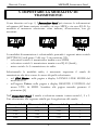
viscount
Annunciator Panel
Manuale d'Uso - IT
User Manual - EN
Ver. 1.0
viscount Annunciator Panel
Manuale Utente
INDICE
1. Note importanti .................................................................................. 2
1.1 Cura del prodotto ......................................................................................... 2
1.2 Note riguardanti il manuale ......................................................................... 2
2. Introduzione ....................................................................................... 4
3. Comandi e connessioni ...................................................................... 5
4. Normale funzionamento .................................................................... 7
5. Impostare la modalita’ di trasmissione ............................................. 8
6. Aggiornamento del firmware ............................................................. 9
1
viscount Annunciator Panel
Manuale Utente
1. NOTE IMPORTANTI
1.1 CURA DEL PRODOTTO
Non applicate eccessiva forza alle strutture ed ai comandi del dispositivo
(interruttori, connettori, ecc…).
Non collocare, quando possibile, il dispositivo in prossimità di unità che
producano forti interferenze come apparecchi radio – TV, monitor,
ecc...
Evitate di posizionare il dispositivo in prossimità di fonti di calore, in
luoghi umidi o polverosi o nelle vicinanze di forti campi magnetici.
Evitate di esporre il dispositivo all’irradiazione solare diretta.
Non introdurre per nessuna ragione oggetti estranei o liquidi di qualsiasi
genere all’interno il dispositivo.
Per la pulizia usate solo un pennello morbido od aria compressa, non
usate mai detergenti, solventi od alcool.
Collegate il cavo di alimentazione ad una presa di corrente provvista di
contatto di terra.
Accertatevi che la tensione di rete corrisponda a quella indicata sulla
targhetta matricola dell’apparato.
In caso di lunghi periodi di inutilizzo scollegate la spina della presa di
corrente.
1.2 NOTE RIGUARDANTI IL MANUALE
Conservate con cura questo manuale.
Il presente manuale costituisce parte integrante il dispositivo. Le
descrizioni e le illustrazioni contenute nella presente pubblicazione si
intendono non impegnative.
Ferme restando le caratteristiche essenziali dello strumento, il costruttore
si riserva il diritto di apportare eventuali modifiche di parti, dettagli ed
accessori che riterrà opportune per il miglioramento del prodotto o per
esigenze di carattere costruttivo o commerciale, in qualunque momento
2
viscount Annunciator Panel
Manuale Utente
e senza impegnarsi ad aggiornare tempestivamente questa pubblicazione.
Tutti i diritti sono riservati, è vietata la riproduzione di qualsiasi parte di
questo manuale, in qualsiasi forma, senza l’esplicito permesso scritto del
costruttore.
Tutti i marchi citati all’interno del manuale sono di proprietà delle
rispettive case produttrici.
Leggete attentamente tutte le informazioni descritte. Eviterete inutili
perdite di tempo ed otterrete le migliori prestazioni dal dispositivo.
Le sigle od i numeri riportati tra parentesi quadre ([ ]) stanno ad indicare i
nomi di interruttori, led e connettori presenti nel dispositivo. Per
esempio la scritta [RADIO SIGNAL] indica il led RADIO SIGNAL.
Le illustrazioni e le videate del display sono puramente a scopo
informativo e possono differire da quelle che vengono realmente
visualizzate.
3
viscount Annunciator Panel
Manuale Utente
2. INTRODUZIONE
COSA E’ L’Annunciator Panel:
L’Annunciator Panel è un display a 3 cifre, utilizzabile con gli organi della
serie Unico e/o con il lettore di brani musicali Choir Master, atto alla
visualizzazione di numeri che indicano quale brano verrà eseguito.
COME VENGONO VISUALIZZATI I NUMERI:
Il numero viene fornito dal nome del brano caricato, più precisamente dai
primi 3 caratteri del nome del file seguiti dal carattere “underscore” (per es.
001_Kyrie,eleison.mid). Tenete pertanto presente che con file i cui nomi che
non iniziano con questa sintassi non è possibile visualizzare il numero
sull’Annunciator Panel.
Tramite il Choir Master è inoltre possibile visualizzare un numero a piacere
tenendo premuto il pulsante [A.PANEL] e componendo la cifra utilizzando i
pulsanti numerici della sezione SONG STRUCTURE.
COME SI COLLEGA L’Annunciator Panel:
L’Annunciator Panel può ricevere le informazioni via radio o via cavo. Il
collegamento via radio non necessita di alcuna connessione, ma in caso di
utilizzo con gli organi Unico occorre installare all’interno dell’organo
l’apposito ricevitore fornito con il radiocomando Remote Radio Controller
(a tal fine consultare il manuale d’uso del radiocomando).
Il collegamento via cavo è fattibile utilizzando la connessione MIDI oppure
tramite cavo con connettore RJ-45 diretto EIA/TIA-568B (se la distanza
dell’Annunciator Panel è superiore ai 15 metri i cavi RJ-45 sono di più facile
reperibilità rispetto a quelli MIDI). I collegamenti possibili sono i seguenti:
- se il brano viene riprodotto da un organo Unico: da [MIDI OUT]
dell’organo a [MIDI IN] dell’Annunciator Panel utilizzando un cavo
MIDI.
- se il brano viene riprodotto dal Choir Master : da [A.PANEL] del Choir
Master a [CHOIR MASTER] dell’Annunciator Panel utilizzando un cavo
RJ-45.
- se il brano viene riprodotto dal Choir Master ma non si ha a disposizione
un cavo con connettore RJ-45: da [MIDI THRU] dell’organo Unico o
dello strumento con il quale si stanno suonando i brani letti dal Choir
Master a [MIDI IN] dell’Annunciator Panel utilizzando un cavo MIDI.
4
viscount Annunciator Panel
Manuale Utente
3. COMANDI E CONNESSIONI
1. Led [RADIO SIGNAL]: indica che l’Annunciator Panel sta ricevendo
un segnale radio.
2. Led [DATA RECEIVED]: indica che il segnale radio è stato ricevuto
ed interpretato.
La presenza di questi due led è utile per capire se l’Annunciator Panel sta
ricevendo il segnale radio trasmesso dal Choir Master o dall’organo
Unico e se questo viene interpretato.
5
viscount Annunciator Panel
Manuale Utente
Se entrambi i led non si accendono ciò sta a significare che l’Annunciator
Panel non sta ricevendo alcun segnale radio. In caso di utilizzo con un
organo Unico verificare la corretta installazione del ricevitore radio al
suo interno. In caso di utilizzo con il Choir Master verificare che sia
selezionata la modalità di trasmissione radio nella pagina a display
A.PANEL LINK MODE del menu SETUP. Se tutto ciò risulta corretto
contattare l’assistenza tecnica all’indirizzo e-mail [email protected] in
quanto ci potrebbero essere problemi agli apparati radio.
Se è il solo led rosso ad accendersi ad impulsi regolari ciò sta a significare
che l’Annunciator Panel sta ricevendo un segnale radio ma non riesce ad
interpretarlo, molto probabilmente a causa del canale radio errato.
Verificare che il canale impostato tramite i micro-switch [SETTINGS]
(vedi punto 9) e visualizzato dopo aver acceso l’Annunciator Panel sia lo
stesso di quello impostato:
o nel Choir Master : nella pagina a display A.PANEL LINK MODE del
menu SETUP
o nell’organo Unico: nella pagina a display REMOTE CONTROL del
menu UTIL. & MIDI. Accedere alla pagina tenendo premuto il
pistoncino [S].
Se è il solo led rosso ad accendersi frequentemente, se non a rimanere
continuamente acceso, ciò sta a significare che l’Annunciator Panel si
trovare in un’area con forti segnali e/o disturbi radio. In questo caso
provare ad installarlo in un altra posizione e/o ruotare l’antenna.
3. Connettore [MIDI IN]: connettore DIN a 5 poli per la ricezione dei
dati MIDI. I collegamenti effettuabili sono descritti nel cap. 2.
4. Connettore [CHOIR MASTER]: connettore RJ-45 per la ricezione
dei dati da utilizzarsi con cavo diretto EIA/TIA-568B. I collegamenti
effettuabili sono descritti nel cap. 2.
5. Connettore [AC INPUT]: inserire qui il cavo di alimentazione fornito
con il dispositivo.
6. Interruttore [POWER ON]: interruttore di accensione e spegnimento.
7. Connettore [:]: inserire ed avvitare qui l’antenna fornita in dotazione
con il dispositivo.
8. Staffa per il fissaggio a muro con fori da 8 mm.
6
viscount Annunciator Panel
Manuale Utente
9. Micro-switch [SETTINGS]: micro-switch per la selezione della
modalità di trasmissione dei dati, il canale radio ed il numero
identificativo del dispositivo. Per maggiori informazioni consultare il
cap. 5.
N.B.:
- Il nome di ogni comando e connessione è serigrafato nel lato
posteriore dell’Annunciator Panel.
- Sebbene si utilizzino comuni cavi Ethernet, la connessione via cavo
RJ-45 non è di tipo Ethernet, ma è di tipo seriale RS-485. Quindi non
è possibile collegare l’Annunciator Panel a dispositivi Ethernet.
4. NORMALE FUNZIONAMENTO
Subito dopo l’accensione il display visualizza la release del firmware
attualmente installato indicata con la lettera “r”. Se è selezionata la modalità
di trasmissione radio vengono inoltre forniti il canale ed il numero
identificativo del dispositivo impostati con i micro-switch [SETTINGS]
(vedi cap. 5), indicati rispettivamente da una lettera “c” ed una “d”.
Questa una sequenza di esempio delle videate di accensione:
dopo le quali il dispositivo è pronto per ricevere le informazioni sul numero
del brano caricato.
Se viene caricato un brano il cui nome non inizia con tre numeri (vedi anche
cap. 2) il display visualizza tre trattini:
Se non viene ricevuto alcun segnale radio entro 5 secondi (se, per esempio,
l’organo Unico o il Choir Master sono stati spenti), il dispositivo viene
automaticamente spento.
7
viscount Annunciator Panel
Manuale Utente
5. IMPOSTARE LA MODALITA’ DI
TRASMISSIONE
Come descritto nel cap. 2, l’Annunciator Panel può ricevere le informazioni
sul numero del brano caricato via radio, via cavo MIDI o via cavo RJ-45. La
modalità al momento selezionata viene indicata, all’accensione, con gli
acronimi:
La modalità di trasmissione è selezionabile ponendo i seguenti micro-switch
[SETTINGS] (vedi punto 9 del cap. 3) in posizione ON:
- solo micro-switch 4: trasmissione tramite cavo MIDI;
- solo micro-switch 5: trasmissione tramite cavo RJ-45 (Serial);
- micro-switch 4 e 5: trasmissione via radio.
Selezionando la modalità radio, è necessario impostare il canale di
trasmissione che deve essere lo stesso di quello selezionato:
o nel Choir Master : nella pagina a display A.PANEL LINK MODE del
menu SETUP
o nell’organo Unico: nella pagina a display REMOTE CONTROL del
menu UTIL. & MIDI. Accedere alla pagina tenendo premuto il
pistoncino [S].
Nell’Annunciator Panel il canale si seleziona tramite i micro-switch 1, 2 e 3.
Fate riferimento alla seguente tabella per la regolazione del canale:
Micro-switch 1
ON
OFF
ON
OFF
Micro-switch 2
ON
ON
OFF
OFF
Micro-switch 3
ON
ON
ON
ON
8
Canale
0
1
2
3
viscount Annunciator Panel
Micro-switch 1
ON
OFF
ON
OFF
Manuale Utente
Micro-switch 2
ON
ON
OFF
OFF
Micro-switch 3
OFF
OFF
OFF
OFF
Canale
4
5
6
7
Sempre in modalità radio, qualora siano presenti più Annunciator Panel , per
essere sicuri che tutti i dispositivi ricevano correttamente le informazioni sul
numero del brano caricato, è necessario assegnare ad ognuno un diverso
numero identificativo del dispositivo. Questo si assegna tramite i microswitch 6, 7 e 8. Fate riferimento alla seguente tabella per l’assegnazione del
numero identificativo di dispositivo:
Micro-switch 6
ON
OFF
ON
OFF
ON
OFF
ON
OFF
Micro-switch 7
ON
ON
OFF
OFF
ON
ON
OFF
OFF
Micro-switch 8
ON
ON
ON
ON
OFF
OFF
OFF
OFF
N.° dispositivo
0
1
2
3
4
5
6
7
6. AGGIORNAMENTO DEL FIRMWARE
Qualora si reputi necessario aggiornare il firmware dell’Annunciator Panel ,
Viscount fornirà un file nominato vvv_pnlupl.mid, dove vvv sta ad indicare
la versione del nuovo firmware. Per caricarlo è dapprima necessario
collegare il connettore [MIDI IN] dell’Annunciator Panel al MIDI OUT del
dispositivo che riproduce il file .mid, che può anche essere lo stesso Choir
Master o organo Unico del quale si visualizzano i numeri dei brani.
Fatto ciò, è sufficiente riprodurre il file in questione (nel caso di organo
Unico tramite il sequencer interno), alla ricezione dei dati il display
dell’Annunciator Panel visualizza le diciture “btU” (Boot Upload) e ”UPL”
(Upload) con i tre punti che si accendono alternativamente. Al termine della
procedura viene visualizzata la dicitura “End” dopodichè il dispositivo
effettua una autoriaccensione.
9
Smaltimento dei rifiuti elettrici ed elettronici (applicabile nell’Unione Europea e negli altri paesi
europei con servizio di raccolta differenziata)
Ai sensi dell’art. 13 del Decreto legislativo 25 luglio 2005, n. 151 “Attuazione delle Direttive
2002/95/CE, 2002/96/CE e 2003/108/CE”
II simbolo presente sul prodotto o sulla sua confezione indica che il prodotto non verrà trattato come
rifiuto domestico. Sarà invece consegnato al centro di raccolta autorizzato per il riciclo dei rifi uti
elettrici ed elettronici. Assicurandovi che il prodotto venga smaltito in modo adeguato, eviterete un
potenziale impatto negativo sull’ambiente e la salute umana, che potrebbe essere causato da una
gestione non conforme dello smaltimento del prodotto. Il riciclaggio dei materiali contribuirà alla
conservazione delle risorse naturali. Per ricevere ulteriori informazioni più dettagliate Vi invitiamo a
contattare l’uffi cio preposto nella Vostra città, il servizio per lo smaltimento dei rifi uti o il negozio in
cui avete acquistato il prodotto.
Lo smaltimento del prodotto da parte dell’utente comporta l’applicazione delle sanzioni amministrative
previste dalla normativa di legge.
Questo prodotto è conforme ai requisiti delle direttive EMCD 2004/108/EC e LVD 2006/95/EC.
User Manual
Annunciator Panel
INDEX
1. Important notes ................................................................................ 14
1.1 Looking after the product ......................................................................... 14
1.2 Notes about the manual............................................................................. 14
2. Introduction ..................................................................................... 16
3. Comandi e connessioni .................................................................... 17
4. Normal functioning ......................................................................... 19
5. Setting the transmission mode ........................................................ 20
6. Firmware update .............................................................................. 21
13
User Manual
viscount Annunciator Panel
1. IMPORTANT NOTES
1.1 LOOKING AFTER THE PRODUCT
Do not apply excessive force to the device’s structures or the controls
(switches, connectors etc.).
When possible, do not place the device close to units which generate
strong interference, such as radios, TVs, computer videos, etc.
Do not place the device close to heat sources, in damp or dusty places or
in the vicinity of strong magnetic fields.
Do not expose the device to direct sunlight.
Never insert foreign bodies inside the device or pour liquids of any kind
into it.
For cleaning, use only a soft brush or compressed air; never use
detergents, solvents or alcohol.
Connect the net cable to an earthed socket.
Check that the voltage corresponds to the voltage shown on the serial
number plate of the device.
If the product is to be out of use for lengthy periods, disconnect the
plug from the power socket.
1.2 NOTES ABOUT THE MANUAL
Take good care of this manual.
This manual is an integral part of the instrument. The descriptions and
illustrations in this publication are not binding.
While the device’s essential characteristics remain the same, the
manufacturer reserves the right to make any modifications to parts,
details or accessories considered appropriate to improve the product or
for requirements of a constructional or commercial nature, at any time
and without undertaking to update this publication immediately.
14
User Manual
Annunciator Panel
All rights reserved; the reproduction of any part of this manual, in any
form, without the manufacturer’s specific written permission is
forbidden.
All the trademarks referred to in this manual are the property of the
respective manufacturers.
Read all the information carefully in order to obtain the best
performances from your product and waste no time..
The codes or numbers in square brackets ([]) indicate the names of the
buttons, sliders, trimmers and connectors on the device. For example,
[RADIO SIGNAL] refers to the RADIO SIGNAL led.
The illustrations and display pages are purely guideline and may differ
from those actually shown on the display.
15
User Manual
viscount Annunciator Panel
2. INTRODUCTION
WHAT IS THE Annunciator Panel:
The Annunciator Panel is a three-digit display, compatible with Unico organs
and the music player Choir Master Its purpose is to show a number
indicating the song to be performed next.
NUMBER VISUALISATION
The number appearing on screen derives from the name of the loaded song:
the first three digits of the name, followed by the "underscore" symbol. (e.g.
001_Kyrie,eleison.mid). Keep in mind that the Annunciator Panel can only
work if the name of the loaded song follows this syntax.
The Annunciator Panel can also show any other digit sequence. To assign a
sequence manually, press the [A.PANEL] button on your Choir Master and
in the meanwhile enter the digits using the SONG STRUCTURE buttons.
CONNECTING THE Annunciator Panel:
The Annunciator Panel can be connected via radio waves or cable. The radio
connection is wireless. In order to use the radio connection with Unico
organs, it is necessary to install in the organ itself a receiver, provided with a
Remote Radio Controller (see the remote control user manual).
To connect the Annunciator Panel via cable, use either a MIDI connection
or an RJ-45 cable, direct EIA/TIA-568B. For distances of 15 metres or
more, RJ-45 cable are a better option since they are easier to find than MIDI
cable of the same length. Possible connections are:
- If the song is played on an Unico organ: from [MIDI OUT] of the
organ to [MIDI IN] of the Annunciator Panel, through a MIDI cable.
- If the song is played by the Choir Master : from [A.PANEL] on the Choir
Master to [CHOIR MASTER] on the Annunciator Panel, through a RJ45 cable.
- If the song is played on the Choir Master but there is not RJ-45 cable
available: from [MIDI THRU] on the Unico organ (or other instrument
through which the Choir Master is playing) to the [MIDI IN] of the
Annunciator Panel, through MIDI cable.
16
User Manual
Annunciator Panel
3. CONNECTIONS AND CONTROLS
1. [RADIO SIGNAL] led: indicates that the Annunciator Panel
is
receiving a radio signal.
2. [DATA RECEIVED] led: indicates that the radio signal has been
received and understood.
These two leds help understand if the Annunciator Panel is receiving
signal from the Choir Master or from the Unico organ, and whether the
signal has been successfully understood.
17
User Manual
viscount Annunciator Panel
If neither led is on, it means that the Annunciator Panel is not receiving
any signal. When connecting the Annunciator Panel to a Unico organ,
check that the receiver within the organ has been installed correctly.
When connecting with Choir Master, check that the radio transmission
mode has been selected in the A.PANEL LINK MODE page under the
SETUP menu. If the problem persists, it might be due to malfunctioning
radio devices. Should this happen, please contact the technical support at
the email address [email protected].
If the red led only blinks at regular interval, it means that the Annunciator
Panel receives the signal but is not able to understand it. In this case a
radio channel error is likely. Should this happen, check that the radio
channel set through the [SETTINGS] micro-switch (see chap. 9) and
visualized after switching on the Annunciator Panel corresponds to the
channel set:
o on the Choir Master , on the A.PANEL LINK MODE page under
the SETUP menu.
o on the Unico organ, on the REMOTE CONTROL video page
under the UTIL. & MIDI menu. To access this page press and hold
the [S] piston.
If the red led only blinks frequently but does not remain on, this means
that the Annunciator Panel is surrounded by heavy radio disturbance. Try
installing the device in a different location and/or rotating the antenna.
3. [MIDI IN] connector: 5 pins DIN connector, receives MIDI data.
Available connections are described in chap. 2.
4. [CHOIR MASTER] connector: RJ-45 connector. Use with direct
cable EIA/TUA-568B. Available connections are describe in chap. 2.
5. [AC INPUT] connector: insert here the power cable (included).
6. [POWER ON] switch: on/off switch.
7. [ : ] connector: insert and screw in here the antenna provided with the
device.
8. Wall hanging support with 8mm holes.
9. [SETTINGS] micro-switches: select data transmission mode, radio
channel and the identification number of the device. For further
information, see chap. 5.
18
User Manual
Annunciator Panel
N.B.:
- Names for each control and connection are printed on the back of the
Annunciator Panel.
- Although performed through Ethernet cable, the RJ-45 connection is not
an Ethernet connection, but a serial RS-485 type. Therefore, the Annunciator
Panel cannot be connected to any Ethernet device.
4. NORMAL FUNCTIONING
As soon as the display is switched on, it shows the firmware release currently
installed, indicated by an "r". If using the radio transmission mode, the
device also shows the radio channel and identity number of the device, set
through the [SETTINGS] micro switches (see chap. 5), "c" stands for
channel and "d" for identity number.
This is an example of the video pages:
then the device is ready to receive the song codes.
When loading a song whose filename does not begin with three digits (see
also chap. 2) the display shows three dashes:
If the device does not detect any radio signal within 5 seconds (if, for
example, the Unico organ or the Choir Master are switched off) it will
automatically shut down.
19
User Manual
viscount Annunciator Panel
5. SETTING THE TRANSMISSION MODE
As described in chap. 2, The Annunciator Panel can be connected via radio
waves, MIDI cable or RJ-45 cable. The currently selected transmission mode
is shown when the display is switched on. Acronyms are:
The transmission mode can be selected by pulling the following
[SETTINGS] micro switches in ON position (see point 9 chap. 3):
- only micro-switch 4: MIDI cable transmission;
- only micro-switch 5: RJ-45 (serial) cable transmission;
- micro-switches 4 and 5: radio transmission.
Selecting radio mode, it is necessary to set also the radio channel, that must
correspond to the one set:
o on the Choir Master, on the A.PANEL LINK MODE page under the
SETUP menu.
o on the Unico organ, in the REMOTE CONTROL video page under
the UTIL. & MIDI menu. To access this page press and hold the [S]
piston.
Select the radio channel of the Annunciator Panel through its micro-switches
1, 2 and 3. To adjust the channel, use the following chart:
Micro-switch 1
ON
OFF
ON
OFF
ON
OFF
Micro-switch 2
ON
ON
OFF
OFF
ON
ON
Micro-switch 3
ON
ON
ON
ON
OFF
OFF
20
Channel
0
1
2
3
4
5
viscount Annunciator Panel
Micro-switch 1
ON
OFF
User Manual
Micro-switch 2
OFF
OFF
Micro-switch 3
OFF
OFF
Channel
6
7
While in radio mode, if using more than one Annunciator Panel, each device
should be assigned a different identity number. To do so, use the microswitches 6, 7 and 8. To assign an identity number, use the following chart:
Micro-switch 6
ON
OFF
ON
OFF
ON
OFF
ON
OFF
Micro-switch 7
ON
ON
OFF
OFF
ON
ON
OFF
OFF
Micro-switch 8
ON
ON
ON
ON
OFF
OFF
OFF
OFF
Device n.°
0
1
2
3
4
5
6
7
6. FIRMWARE UPDATE
When necessary, Viscount will release firmware updates. The update will be
delivered in a file named vvv_pnlupl.mid, where vvv stands for the number
of the new firmware release. To load this file, first connect the [MIDI IN]
connector of the Annunciator Panel to the MIDI OUT port of the MIDI
player you are using, be it the Choir Master or a Unico organ.
Now play the file (if you are using a Unico organ, do so via the internal
sequencer). While receiving data, the Annunciator Panel shows the acronyms
"btU" (Boot Upload) and "UPL" (Upload), with three progressing dots. At
the end of the process, the word "End" appears on screen. Then, the device
reboots.
21
Disposal of old Electrical & Electronic Equipment (Applìcable throughout the European Union
and other European countries with separate collection programs)
Dir. 2002/95/CE, 2002/96/CE e 2003/108/CE
This syrnbol, found on your product or on its packaging, indicates that this product should not be
treated as household waste when you wish to dispose of it. Instead, it should be handed overt to an
applicable collection point for the recycling of electrical and electronic equipment. By ensuring this
product is disposed of correctly, you will help prevent potential negative consequences to the
environment
and human health, which could otherwise be caused by inappropriate disposal of this product. The
recycling of materials will help to conserve natural resources. For more detailed information about the
recycling of this product, please contact your local city offi ce, waste disposal service or the retail store
where you purchased this product.
This product complies with the requirements of EMCD 2004/108/EC and LVD 2006/95/EC.
FCC RULES
NOTE: This equipment has been tested and found to comply with the limits for a Class B digital Device, persuant to Part 15 if the FCC
Rules. These limits are designed to provide reasonable protection against harmful interference in a residential installation. This
equipment generates, uses and can radiate radio frequency energy and, if not installed and used in accordance with the instruction,
may cause harmful interference to radio comunications. However, there is no guarantee that the interference will not occur in a
particular installation. If this equipment does cause harmful interference to radio or television reception, which can be determinated by
turning the equipment off and on, the user is encuraged to try to correct the interference by one or more of the following measures:
-
Reorient or relocate the receiving antenna.
Increase the separation between the equipment and receiver.
Connect the equipment into an outlet on a circuit different from that to which the receiver is connected.
Consult the dealer or an experienced Radio/Tv technician for help.
The user is cautioned that any changes or modification not expressly approved by the party responsable for compliance could void the
user’s authority opearate the equipment.
INFORMATIONS FCC
NOTE : Cet instrument a été controlé et il est garanti pour etre en conformité avec les spécifications techniques établies pour les
dispositifs numériques de la « Classe B » selon les normes de protection contre les interférences avec d’autres dispositifs électroniques
environnants. Cet appareil produit et utilise des fréquences radio. S’il n’est pas installé et utilisé selon les instructions contenues dans le
mode d’emploi, il peut générer des interférences. L’observation des normes FCC ne garanti pas qu’il y aura aucune interférence. Si cet
appareil est la cause d’ interférences avec une réception Radio ou TV, il est possible
de le vérifier en éteignant puis en allumant l’instrument : Vous pouvez alors résoudre le problème en suivant les procédures suivantes :
-
déplacer ou orienter l’antenne de l’appareil avec lequel se manifeste l’interférence.
déplacer cet instrument ou l’appareil avec lequel se produit l’interférence
connecter cet instrument à une prise de courant différente afin de mettre les deux appareils sur deux circuits différents.
consulter le revendeur ou un technicien radio/tv pour d’autres renseignements.
D’éventuelles modifications non approuvées par le constructeur peuvent annuler votre garantie de l’appareil.
viscount
Viscount International S.p.A.
Via Belvedere Fogliense 154 – 47836 Mondaino (RN), ITALY
Tel: +39-0541-981700 Fax: +39-0541-981052
Website: www.viscount.it
Distribuito in Italia da
TITAN MUSIC S.A.
Strada Genghe di Atto, 80
47892 Acquaviva - Repubblica di San Marino
Tel. 0549-999164
fax 0549-999490