1
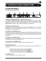
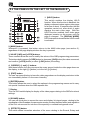
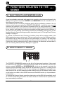
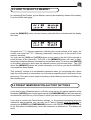
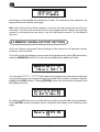
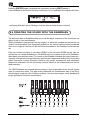
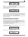
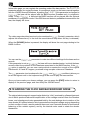
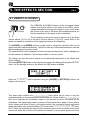
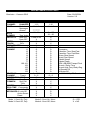
DB-5 Operating Manual- DB5 CAUTION RISK OF ELECTRIC SHOCK DO NOT OPEN WARNING! TO REDUCE THE DANGER OF ELECTRIC SHOCK: DO NOT REMOVE COVER (OR BACK) DO NOT EXPOSE THIS APPLIANCE TO RAIN OR MOISTURE NO USER SERVICEABLE PARTS INSIDE REFER SERVICING TO QUALIFIED SERVICE PERSONNEL This simbol is intended to alert the user to the presence of important operating and maintenance (servicing) instructions in the literature accompanying the appliance. This simbol is intended to alert the user to the presence of uninsulated “dangerous voltage“ within the product’s enclouser that may be of sufficient magnitude to constitute a risk of electronic shock to persons. “INSTRUCTIONS PERTAINING TO A RISK OF FIRE, ELECTRIC SHOCK, OR INJURY TO PERSONS“ IMPORTANT SAFETY INSTRUCTIONS WARNING: When using electric products, basic precautions should always be fallowed, including the following: 1) Read all instructions before using the product. 2) To reduce risk of injury, close supervision is necessary when product is used near children. 3) Do not use this product near water – for example, near a batnub, washbowl, kitchen sink, in a wet basement, or near a swimming pool, or the like. 4) This product, either alone or in combination with an amplifier and headphones or speakers, may be capable of producing sound levels that could cause permanent hearing loss. Do not operate for a long period of time in high volume level or at a level that is unconfortable. If you experience any hearing loss or ringing in the ears, you should consult an audiologist. 5) This products should be located away from heat sources such as radiators, heat register, or other products that produce heat. 6) The power supply cord of the instrument should be unplugged from the outlet when left unused for a long period of time. 7) Care should be taken so that objects do not fall and liquids are not spilled into the enclosure of the instrument. 8) The products should be serviced by qualified personnel when: a. The power supply cord or the plug has been demaged; or b. Objects have fallen, or liquid has been spilled into the product; or c. The products has been exposed to rain; or d. The products does not appear to operate normally or exibist a marked change in performance; or e. The products has been dropped, or the enclosure demaged. 9) Do not attemp to service the product beyond that described in the user-maintenance instructions. All other servicing should be referred to qualified personnel. CONTENTS OB5 1. Important Notes ....................................................................................................... 45 1.1 Notes on the OB5 .................................................................................................... 45 1.2 Notes about manual ................................................................................................ 46 2. Controls and connectors ........................................................................................ 47 2.1 The top panel .......................................................................................................... 47 2.2 The panel on the left of the manual......................................................................... 48 2.3 The rear panel ......................................................................................................... 50 3. Connecting and switching on the OB5 .................................................................51 3.1 Connection example................................................................................................ 51 3.2 Switch on the OB5................................................................................................... 52 3.3 The instrument is ready to play ............................................................................... 52 3.4 Switching off ............................................................................................................ 53 4. Functions relating to the sound .............................................................................54 4.1 What Presets and Memories are.............................................................................54 4.2 How to select a Preset ............................................................................................ 54 4.3 How to select a Memory .......................................................................................... 55 4.4 Presets memorisation - Factory Settings ................................................................ 55 4.5 Memory memorisation - Factory Settings ................................................................ 56 4.6 Creating the sound with the Drawbars .................................................................... 58 4.7 Adding character to the sound ................................................................................ 59 4.8 Adding percussion................................................................................................... 59 4.9 Setting operation of the bass .................................................................................. 61 4.10 Adding Click and background noise ...................................................................... 62 5. The effect section ................................................................................................... 64 5.1 Vibrato & Chorus .....................................................................................................64 5.2 Reverb ..................................................................................................................... 65 5.3 Rotary ...................................................................................................................... 66 5.4 Overdrive.................................................................................................................67 6. Using a remote rotary tone cabinet ....................................................................... 68 43 7. Utility ........................................................................................................................ 70 7.1 MIDI ......................................................................................................................... 70 7.2 Setting the MIDI functions ....................................................................................... 71 7.3 Instrument tuning .................................................................................................... 73 7.4 Adjusting the display contrast ................................................................................. 74 7.5 Assigning specific function to the pedal .................................................................. 74 8. Using the MIDI ......................................................................................................... 77 8.1 Parameters controllable by means Control Change ............................................... 77 8.2 Parameters controllable by means System Exclusive ............................................. 79 9. Technical Specifications ........................................................................................ 81 44 1. IMPORTANT NOTES OB5 1.1 NOTES ON THE OB5 LOOKING AFTER THE PRODUCT • Do not apply excessive force to the structures and controls (knobs, switches, etc.). • Protect the instrument from heavy stresses during both transport and use. The instrument should only be transported in its original packaging or an equivalent. • Do not place the OB5 close to heat sources, in damp or dusty places, or close to strong magnetic fields. • When possible, do not place the instrument close to units which produce strong interference, such as radios, TVs, monitors, etc. • Never put foreign objects or liquids of any kind inside the device, for any reason. • For cleaning, use only a soft cloth or compressed air; never use detergents, solvents or alcohol. • Do not expose the instrument to direct sunlight. • Never hit or apply excessive force to the display. • The instrument contains a buffer battery which maintains the data present in the RAM memory. The lifetime of this battery is normally 3 years; for replacement, contact a specialist service centre and take care to transfer all programming data to a MIDI unit capable of memorising Exclusive System messages. CONNECTING TO THE ELECTRICAL MAINS • To avoid the risk of electric shock, do not make connections with wet hands. • Connect the power supply lead to a mains jack complete with earth contact. CONNECTING TO OTHER INSTRUMENTS • Always use good quality screened cables. When disconnecting cables from connectors, always take hold of them by the connector and not by the cable itself; when coiling, take care not to form knots or to twist cables. • Before making connections, check that the other units (especially amplification and speaker systems) you are about to connect are switched off. This will avoid noisy or 45 hazardous signal peaks. 1.2 NOTES ABOUT THE MANUAL • Take good care of this manual. • Read all the information provided in this manual carefully. You will avoid wasting time and will obtain the best performance from your instrument. • Codes or numbers in square brackets ([]) indicate the names of buttons, sliders or trimmers on the instrument panel. For example, the word [REVERB] indicates the REVERB trimmer. • Illustrations and display video pages are purely guideline and may be different from those which actually appear on the LCD. 46 2. CONTROLS AND CONNECTORS OB5 2.1 THE TOP PANEL 1. PRESET DRAWBARS UPPER – LOWER & BASS section. This section contains the buttons for selection of the six PRESETS relating to the timbre of the UPPER, LOWER and BASS manuals (the BASS is the section of the lower manual assigned to the bass, or to the optional pedalboard if this is connected to the rear PEDALBOARD connector), and for manual operation of the Drawbars. 2. VIBRATO & CHORUS section. This section includes a knob for selection of the six types of VIBRATO (V1 – V2 – V3) and CHORUS (C1 – C2 – C3) effects and the two switches for assigning the selected effect to the UPPER and LOWER manuals. 3. Drawbars for the UPPER section. The harmonic bars or Drawbars can be used to set the basic features of the timbre in use. Each Drawbar sets the volume of the harmonic in relation to the fundamental (8’), indicated above the respective bar. In this Drawbars section, the sound of the UPPER manual can be adjusted. 4. Drawbars for the BASS section. In this section, the two drawbars provided can be used to adjust the sound of the pedalboard of the BASS section of the LOWER manual. 5. Drawbars for the LOWER section. This Drawbar section contains the drawbars for the LOWER manual. 6. PERCUSSION section. These buttons allow the user to add percussion to the timbre in use on the UPPER manual, as follows: - to add second harmonic percussion using the [2nd] key to add third harmonic percussion using the [3rd] key to vary the volume of the percussion using the [SOFT] key to vary the percussion decay time using the [DECAY] key 7. [POWER] switch. You will use this switch to turn the OB5 on and off. 47 2.2 THE PANELS ON THE LEFT OF THE MANUALS 1. [HOLD] button. This switch enables the display HOLD function. When this function is disabled, the display continues to show a given video page for a time of about 10 seconds after the last operation carried out, after which it again displays the main video page. With the HOLD function enabled, each video page displayed remains on the screen until the page is changed. The [DISPLAY MODE] LED illuminates to show that the HOLD mode is activated. 2. [MAIN] button. Whenever it is pressed, this button returns to the MAIN video page (see section 3), regardless of the page displayed when the key is pressed. 3. VALUE [-/NO] and [+/YES] buttons. These controls allow the user to modify the values of the OB5 programming parameters. The buttons both increase ([+/YES] button) or decrease ([-/NO] button) the value concerned, and confirm ([+/YES] button) or abort ([-/NO] button) the setting. 4. CURSOR [ï] and [ð] buttons. With these buttons, the user can move the cursor around inside the video page shown on the display, to the right ([ð] button) or to the left ([ï] button). 5. [EXIT] button. The user can press this key to leave the video page shown on the display and return to the one immediately before it in the menu hierarchy 6. [ENTER] button. This button allows the user to select the options in the programming menus and to carry out special functions when the OB5 requests this. 7. Display. This is a 2x16 backlit display for display of the video pages relating to the OB5’s functions/ settings. 8. [SOUND] button. You can use this button to access the menu and display its internal pages, relating to the equalisation of the Drawbars, the percussion modes, the way the Bass works, and regulation of the Click volume and the volume of the specially re-created background noise. 9. [EFFECTS] button. This switch allows immediate selection of the menu relating to the Reverb, Rotary and 48 Vibrato effects, and display of the pages it contains. 10. [UTILITY] button. Pressing this button gives access to the menu of system utilities such as setting of the MIDI functions, instrument tuning, assignment of functions to the footswitch pedals and adjustment of the display contrast. As for the other menus, this button can be used to display the pages within the Utility section. 11. [MEMORY] button. Pressing this button once activates the latest memory selected (the LED on the button will illuminate to indicate that it is being loaded). Subsequent Memory selections must be confirmed using [ENTER], since they are first booked (the LED will start to flash). Keeping the [MEMORY] button pressed for at least two seconds gives access to the memory saving or Factory Reset function, in which case the MEMORY LED remains constantly on. 12. [REVERB] trimmer. This trimmer regulates the quantity of the selected reverb effect. With the trimmer turned fully to the left, the effect in question is deactivated. 13. [OVERDRIVE] trimmer. This trimmer can be used to regulate the amount of distortion. With the trimmer turned fully to the left, the Overdrive effect will be eliminated. 14. [PEDAL VOLUME] trimmer. This trimmer regulates the volume of the BASS section. 15. [LOWER VOLUME] trimmer. This control regulates the volume of the LOWER manual. 16. [ROTARY ON/OFF] button. This button turns the Rotary effect ON or OFF, and also switches on and off the motor of the optional rotary tone cabinet connected to the rear [ROTARY TONE CABINET] connector. 17. [ROTARY SLOW/FAST] button. This button can be used to vary the rotation speed (SLOW – FAST) of the Rotary effect, and of the motor of the optional rotary tone cabinet connected to the rear of the instrument. 49 2.3 THE REAR PANEL 1. [PEDALBOARD] connector. This connector allows connection of the optional pedalboard. 2. PEDAL [FOOTSW. I], [FOOTSW. II] and [EXPR.] jacks. Two normally open footswitch pedals, to which a function can be assigned using the system Utilities, can be connected to the [FOOTSW. I] and [FOOTSW. II] jacks, while the [EXPR.] jack can be used to connect an expression pedal for control of the organ’s overall volume. 3. MIDI [IN], [OUT] and [THRU] jacks. These are five-pin DIN jacks for the exchange of MIDI data with remote MIDI units. The MIDI [IN] connector allows receipt of the MIDI data delivered by a remote unit, the MIDI [OUT] port allows sending of the MIDI data generated by the OB5, while the MIDI [THRU] jack picks up the MIDI data received by the MIDI [IN] jack so that the data reaching the OB5 can be transmitted as output. 4. SEND [L(MONO)] and [R] jacks. You can use these jacks to send the signal generated by the OB5, in stereo format, to a remote unit such as an effects processor, so that it can be processed with external effects. If the receving device is monophonic, use the SEND [L(MONO)] jack only. 5. RETURN [L(MONO)] and [R] jacks. These jacks can be used to receive the signal processed by a remote unit such as an effects processor, to which you have sent the original OB5 signal by means of the SEND L/R jacks. If the incoming signal is monophonic, use the RETURN [L(MONO)] jack only. 6. OUTPUT [L(MONO)] and [R] jacks. These are general instrument outputs which send the audio signal in stereophonic form. Connect an amplification system or a mixing bank to these jacks. If you have a monophonic amplification system, use the [L(MONO)] jack only. 7. [HEADPHONES] jack. A headphones set can be connected here. 8. [ROTARY TONE CABINET] connector. As an alternative to the OB5’s internal Rotary effect, or a remote effects processor connected to the SEND and RETURN jacks, you can use a real rotary tone cabinet which can be connected to the 11 pin [ROTARY TONE CABINET] connecting. 50 1. Before making any connection, make sure that the OB5 and the rest of the equipment are switched off. 2. Then connect the OB5 to the electricity supply socket by means of the power supply lead supplied with the instrument. 3.2 SWITCHING ON THE OB5 1. Before switching on the OB5, make sure that the organ volume is at the minimum setting. 2. Press the [POWER] switch on the front panel of the instrument. 3. Switch on the amplification system and the rest of the instruments connected to the OB5. 4. Set the volume of the amplification system to your requirements. 3.3 THE INSTRUMENT IS READY TO PLAY At this point the OB5 is ready to be played. Adjust the volume of the organ after setting the amplification system at the desired level. At switch-on the display will have shown: Operating System Version 2.0 indicating the version of the operating system. After a few seconds, the MAIN video page will be displayed: This video page, which can be displayed at any moment by pressing the [MAIN] button, contains the Vol field, indicating the volume generated by the organ (which can also be controlled by means of an expression pedal connected to the rear [EXPR.] jack) and, on the line below, the levels of the low frequencies(Low field) and the high frequencies (High field). The field alongside the general volume reading is used to display the memory which has been recalled. If no memory is active, the display will show a series of asterisks (as above). N.B.: We have been talking about Memory (Mem. on the display). It must be remembered that the memories which can be selected from the display are different from the Presets which can be recalled using the buttons on the front panel. The method for recalling these two types of memories is also different. All this will be fully described in the “Function relating to the sound” section on page 54. 52 When carrying out operations by means of the display, you can use the HOLD function, allowing you to “freeze” the video page displayed at that time until another page is selected, so that the display will not return to showing MAIN after a time of 7-8 sec., as already described in the “Panels on the left of the manuals - [Hold] button” section on page 48. 3.4 SWITCHING OFF When you decide to stop playing and switch off the instrument, follow these simple rules: 1. Turn down the volume of the OB5 and of your amplification system to the minimum setting. 2. Switch off the amplification system. 3. Switch off the OB5. N.B.: Whenever it is switched on, the OB5 will set with the settings present before the last time it was switched off. Previous programming settings made but not saved (as a Memory or Preset) will be irrevocably lost. 53 4. FUNCTIONS RELATING TO THE SOUND OB5 4.1 WHAT PRESETS AND MEMORIES ARE As we have already mentioned, with regard to the controls on the instrument’s panels, the OB5 has two types of memories: PRESETS and MEMORIES. We will now take a look at the differences between them. The Presets are the 14 memory locations which can be recalled by means of the 14 buttons on the front panel called the PRESETS DRAWBARS, in which the user can only memorise the positions of the harmonic Drawbars set to his own preferences or for the piece he wishes to play. On purchase the instrument is supplied with Presets programmed by our studios, and is able to provide the most widely varying types of sound. However, if you save your own Presets, these settings will be lost immediately, although they can be recalled using the Factory Setting procedure described in point 4.4 “Saving-Preset Factory Settings” on page 57. In contrast, the Memories are 50 memory locations where all the settings made in the OB5 programming menus can be saved. The user can therefore save the Drawbar positions, the specific type of effect to be used for the performance in question, the instrument transposition, whether or not the background noise or Click is to be active, etc. As for the Presets, the Factory Settings function is also provided for the Memories, as described in point 4.5 “Saving- Memory Factory Settings” on page 58. 4.2 HOW TO SELECT A PRESET The PRESETS DRAWBARS section on the left of the front panel contains 14 keys used to recall one of the 14 Presets memorised inside the OB5. As well as these, there are two buttons marked [UPPER] and [LOWER&BASS], which can be pressed to activate the Drawbar manual operating mode, which will be discussed in point 4.6 “Creating sound with the Drawbars” on page 60. The 14 keys relating to the Presets are arranged in two rows; those on the top row recall the sounds relating to the UPPER Manual, while those on the bottom row relate to the LOWER manual and the BASS section (or the pedalboard, if connected). To activate the Preset of choice, press the relative key and the OB5 will immediately recall its contents, illuminating the LED of the relative Preset to confirm that the operation has been successfully concluded. 54 4.3 HOW TO SELECT A MEMORY In contrast with the Presets, a given Memory can only be recalled by means of the display. From the MAIN video page: press the [MEMORY] button; the last memory selected will be activated and the display will show: Alongside the Vol (Volume) parameter, indicating the overall volume of the organ, the screen now shows the Mem. (Memory) parameter, informing you of the number of the memory activated. You may use the [-/NO] and [+/YES] buttons on the panel on the left of the manuals to scroll through all the memories. The LED of the [MEMORY] button will start to flash, informing you that the Memory is booked but not yet made active. To do this, press [ENTER] on the panel referred to above and the selected memory will become active. The LED above the [MEMORY] switch will remain constantly on to inform you that the MEMORY concerned has been loaded. This “booking” function is of considerable importance when you are playing with a given type of sound and wish to use another set of sounds at a specific point in the piece you are performing. This can be done easily by booking a given Memory and then activating it at the required point. 4.4 PRESET MEMORISATION-FACTORY SETTINGS If you wish to save a Drawbar setup in a Preset, press the key for manual operation of the Drawbars ([UPPER] button for the upper manual or [LOWER&BASS] for the lower manual) simultaneously with the key of the Preset in which you wish to memorise the new setup. If you wish to restore the Preset factory settings, i.e. the settings memorised when the instrument was purchased, you can carry out a Factory Settings (of all the Presets) by pressing the [UPPER] e [LOWER&BASS] buttons in the PRESET DRAWBARS section of the front panel simultaneously, when the instrument is switched on. The display will show: 55 informing you that the OB5 is initialising the Presets. On conclusion of the operation, the display will show the MAIN video page. N.B.: When a Preset Factory Settings operation is carried out, the setups saved by the user will be lost irretrievably. To avoid this, save the chosen Presets in specific Memories, and if a Memory Factory Settings operation is to be performed (see next section), carry out a Bulk Dump (see section 7.2) of the Memories concerned. 4.5 MEMORY SAVING-FACTORY SETTINGS As for the Presets, saving and Factory Setting can be carried out on individual memory locations, or all memories. If you wish to save the settings you have made during programming of the OB5 parameters, press the [MEMORY] button for at least two seconds and the display will show: You can use the Memory WRITE field to save your programming in the memory indicated, or in another memory by scrolling through the number of the memory locations using the [-/NO] and [+/YES] buttons. Pressing [ENTER] starts the memorisation procedure and the display will show: by which the OB5 asks you to confirm that you wish to proceed with the memorisation. Press [ENTER] and the procedure will be completed with display of the following video page: 56 If you wish to abort the Memory saving operation, press [EXIT] from the previous video page. If you wish to restore the original contents of one or all the memories, locate the cursor on the [Memory INIT] field and press the [ENTER] button. The display will change to: The Memory INIT field displays the memory location on which the Factory Settings operation will be carried out if the [ENTER] button is pressed. You can use the [-/NO] and [+/YES] switches to scroll through all 50 Memories. After [ENTER] is pressed the display will show: by which the OB5 asks you to confirm the initialisation procedure. Press the [EXIT] button to abort the procedure, or [ENTER] to carry out the Factory Settings operation on the Memory in question, in which case the display will show: to confirm that the operation has taken place. If you wish to carry out a Factory Settings procedure on all the memories, in the video page select the [INIT ALL] field and press the [ENTER] button. The display will request confirmation to proceed with total initialisation of the Memories: 57 Pressing [ENTER] again completes the procedure; pressing [EXIT] aborts it. If the initialisation procedure has been confirmed, on its completion the display will show: confirming that the Factory Settings of all the Memories have been restored. 4.6 CREATING THE SOUND WITH THE DRAWBARS The harmonic bars or Drawbars allow you to set the basic character of the sound you are going to use in your performance. When a Drawbar is pushed right into the organ (i.e. when the numbers on the bar are not visible) it is deactivated; as it is gradually pulled out, the various volume levels (numbered from one to eight on the bar) of the harmonic associated to the Drawbar concerned are set. Each set of harmonic bars (in our case UPPER on the left and LOWER on the right, as well as the two central Drawbars for the BASS section) consists of four white Drawbars, three black ones and two brown. The colour of the Drawbar indicates the type of harmonic, naturally referred to the tempered scale: white for the fundamental and second, fourth and eighth harmonics (octave intervals); black for the twelfth, seventeenth and nineteenth harmonics, and brown for the sub-octave (octave below) of the fundamental and for the third harmonic. The OB5 Drawbars are marked with the length in feet of the pipes of the church organs used to create the notes. The pipe which produced the fundamental was 8 feet long; shortening its length by half (4 feet) provided a note an octave higher, while doubling its length provided a sound an octave lower. 58 The Drawbars can also be pressed in or pulled out while you are playing, giving real time control of the timbre and creation of the most widely varying sounds. To play with the real Drawbar positions (i.e. not with the Preset settings) press the [UPPER] and/or [LOWER&BASS] buttons of the PRESET DRAWBARS section. The [UPPER] allows you to play with the Drawbars associated to the upper manual, while [LOWER&BASS] will enable the Drawbars relating to the lower manual in addition to the BASS section or pedalboard (when connected). 4.7 ADDING CHARACTER TO THE SOUND The OB5 allows you to use 4 types of settings relating to the sound defined by the Drawbars. This lets you further personalise the timbric character of the sound you are going to produce. When you press the [SOUND] button on the panel on the left of the manuals, the display will show the menu of the same name: The [SCALING] field is already selected, so when the [ENTER] or [SOUND] button is pressed, the display will show: In this video page, you can use the Select parameter and the VALUE buttons to select the various equalisation curves. Press [EXIT] and the display will show the SOUND menu again. 4.8 ADDING PERCUSSION Percussion, a typical electromagnetic organ effect, supplies the replica of a harmonic added to those set using the Drawbars, with rapid start and exponential fading. Percussion can only be added on the UPPER manual when playing without legato, i.e. pressing only one key at a time to obtain percussion on all the notes being played. So if you were to play with legato, the percussion effect would only be provided on the first note. What’s more, in the original instrument the sound produced by the 1’ Drawbar used to be eliminated when the percussion was activated, and the OB5 also reproduces this feature. 59 For activating the percussion, there are two buttons in the PERCUSSION section of the front panel called [2nd] and [3rd]. The [2nd] button activates the second harmonic percussion (the octave of the 8’ Drawbar), while the [3rd] adds the third harmonic percussion (the octave and fifth of the 8’ Drawbar, i.e. the twelfth). N.B.: The [2nd] and [3rd] buttons are mutually exclusive, so the two types of percussion cannot be used simultaneously. It is also possible to regulate the volume of the percussion by means of the [SOFT] switch When the key LED is off, the percussion volume will be normal; when [SOFT] is pressed the LED comes on and the percussion volume will decrease. You can use the [DECAY] button to set the time the percussion takes to fade, choosing between two alternatives. When the key LED is off, the decay time will be standard, while if [DECAY] is pressed, the LED comes on and the decay time will be shorter, making the percussion effect “shorter”. It is also possible to make all the settings with regard to the keyboard range to which the percussion is to apply, and the volume of the Drawbars with the percussion active. When the [SOUND] on the OB5 left panel is pressed, the display will show: so locate the cursor on the [PERC] field and press the [ENTER] or [SOUND] buttons; the display will show the following video page: 60 With the Perc. Level parameter you can adjust the level attenuation of the percussion, while Perc. Length sets the decay time rescaling. Obviusly these parameters are strictly correlated with the fuctions enabled by the buttons [SOFT] and [DECAY] located on the upper panel. The TopKey parameter indicates the highest note in the keyboard range on which the percussion is to apply, while DrawbVolAtt (Drawbars Volume Attenuation) allows you to reduce (Yes) the volume of the sound produced by the Drawbars. If this parameter is set as No there will be no variation in the volume of the Drawbars. On completion of the operation, you can press the [EXIT] button to return to display of the SOUND menu video page. 4.9 SETTING OPERATION OF THE BASS The OB5 allows you to play the bass sounds either using a section of the LOWER manual, or using an optional pedalboard connected to the [PEDALBOARD] jack on the rear. When the LOWER manual is used to play the bass sounds, it will also be possible to set the keyboard range to which this section is to be assigned. The two Drawbars (16’ and 8’) used to create the bass sounds (BASS section) are between those of the UPPER and LOWER sections The display allows you to set the various operating parameters of the bass section. From our old friend the SOUND menu: select the [BASS] field and the display will show: 61 In this video page, you can regulate the operating mode of the bass section. The BassMode parameter allows you to play the bass, in monophonic mode, on the lower manual together with the LOWER manual Drawbars, by setting it as Layer. If this parameter is changed to Replace the bass will be played with the BASS section Drawbars only, in polyphonic mode. Finally, if Pedal is selected the BASS section will be played with the optional pedalboard, in polyphonic mode. If the OB5 does not detect a pedalboard connected to the rear, the display will show: The video page described previously also contains the Sust (Sustain) parameter, which adjusts the release time (i.e. the time the sound takes to stop when the key is released). When the [SOUND] button is pressed, the display will show the next page relating to the BASS function: You can use the BassType parameter to make two different settings for the bass section sounds. If this parameter is set as Drawbrs the bass will use a standard setup, in which the bass sounds reflect the positions of the Drawbars associated to the BASS section. If the A3/ B3 option is selected, you can use a setup which re-creates the sounds of the original Hammond A-3 and B-3 organs, produced using complex mixtures of Drawbars The Top parameter (can be showed in the Layer and Replace conditions) allows you to set the highest note in the keyboard range to be used to play the bass section. Once you have made your chosen settings, you can press the [EXIT] button to return to display of the previous page, and then finally the SOUND menu. 4.10 ADDING THE CLICK AND BACKGROUND NOISE The original electromagnetic organs had a distinctive “click” produced by a flawed electronic circuit which produced abnormal amplification of the voltage received from the Drawbar buses, and a background noise generated both by the note leakage due to rotation of the tone wheels (91 toothed wheels, which generated an electrical voltage varying depending on their number of teeth, used to produce the sound, and 5 smooth wheels for mechanical balancing of the rotation system), and by the internal motor used to rotate the wheels themselves. 62 The OB5 is able to provide a detailed reproduction of these features of the original organs; at the time, efforts were made to eliminate them, but today they are part of the typical sound of an electromagnetic organ. When the [SOUND] button is pressed the display will show: Now use the same key or the [ENTER] button to select the [Ck&Noise] field; the display will change to: In this video page, you can use the AttackClick parameter to regulate the volume of the “click” when the keyboard key is pressed, and when it is released by means of the ReleaseClick parameter. When the [SOUND] button is pressed again, the display will show the next page: where you can use the Click type parameter to select two different types of Click, a more open one if the parameter is set as Bright and a more closed one if Dark is selected. When the usual procedure is used to select the next video page, the display will show: where the LeakageNoise parameter can be used to regulate the level of noise due to note leakage, while the Motor Noise parameter allows adjustment of the noise level due to the organ’s internal motor. 63 5. THE EFFECTS SECTION OB5 5.1 VIBRATO & CHORUS The VIBRATO & CHORUS section of the front panel allows Vibrato and Chorus effects to be added to the OB5’s sound. Vibrato modulates the tuning of the signal in cyclic mode, while the Chorus is the sum of the direct and modulated sound (so that the amplitude of the signal is also modulated). The six-position knob can be used to select one of the three Vibrato effects (V1-V2-V3) or the three Chorus effects (C1-C2-C3), which differ in the depth and speed of modulation of the signal provided by the Drawbars. The [UPPER] and [LOWER] buttons can be used to assign the selected effect to the upper and lower manual respectively. The LED on the key concerned illuminates to indicate that the assignment has been made The selected effect can be assigned to both manuals simultaneously, while if assignment to both manuals is disabled, it will not be possible to hear any effect. The display can also be used to adjust two fundamental parameters of the Vibrato and Chorus effects. When the [EFFECTS] button on the left panel is pressed, the display will show the EFFECT menu, for the settings relating to the effects the OB5 makes available: When the [VIBRATO] field is selected using the [ENTER] or [EFFECTS] buttons, the display will change to: This video page contains the VibratoSpeed field, which can be used to vary the modulation speed, or the speed with which the sound will “vibrate” and the VibratoDepth field, set to regulate the modulation depth, or the amount by which the sound will be modulated. The adjustments made by means of these parameters apply to all six effects (three Vibrato and three Chorus), and operate within the modulation speed and depth range affected by each individual effect. This means that if VibratoSpeed:100 is set, the V1 effect will modulate the sound at the maximum speed of the modulant of the effect concerned, while the V2 effect will modulate the sound not at the same speed, but at the 64 highest speed in the range available to the modulant of effect V2. 5.2 REVERB Reverb originates from the sum of the various acoustic reflections produced by a sound in a natural environment. When we clap our hands inside a large reflective building like a church, for example, we will hear a strong resonance which gradually fades. The OB5 Reverb effect emulates this way in which sound resonates inside an enclosed environment. You can use the [REVERB] trimmer on the left panel to adjust the quantity of the reverb effect desired, while the internal parameters which can be shown on the display will allow you to set the type of reverb and the main parameters of the effect. When the [EFFECTS] button is pressed, the display will show the main page of the EFFECT menu: Use the procedure already described to select the show: [REV.] field and the display will In this video page, the REVERB. parameter can be used to set the type of reverb, choosing from: • • • • Hall: reverb of a very large room Room: reverb of a medium-sized room Church: typical reverb of a church Spring: reverb produced by a spring system. In addition to the reverb type selection, the page contains the Time parameter, used to set the reverb fade time, and the HF parameter, used to set the cut-off frequency of a low-pass filter capable of eliminating all the frequencies higher than that set using the parameter concerned. The last REVERB parameter setting activates a Delay effect, featured in the following video page: 65 The parameter sets the time interval between one repetition and the next, while Reg (Regeneration) sets the amount of signal which will be reprocessed with the Delay algorithm, and thus the time after which the repetitions die away. Time 5.3 ROTARY The OB5’s ROTARY algorithm simulates the archetypal effect produced by a rotary tone cabinet connected to the organ. This system became popular with the advent of the electromagnetic organ and consisted of two sections, one for the treble tones and another for the bass tones, which were able to rotate at different speeds. The internal algorithm of the OB5 provides a faithful reproduction of the relative sounds. N.B.: connecting a remote rotary tone cabinet to the rear [ROTARY TONE CABINET] jack automatically disables the internal ROTARY EFFECT. You can use the [ROTARY ON/OFF] switch on the panel on the left of the manuals to activate or deactivate the Rotary effect, while the [ROTARY SLOW/FAST] allows you to select the rotation speed (fast/slow) of the simulated rotary tone cabinet. The display parameters, on the other hand, enable you to select the type of tone cabinet and to adjust the two rotation speeds and the transitions, i.e. the times for switching from high to low speed and vice-versa. After displaying the main page of the EFFECT menu by pressing the [EFFECTS] or [ENTER] buttons, select the [Rotary] field and the display will show: The Rotary parameter can be used to set up the link between the effect of the Rotary and Reverb effects. Refer to the diagram with regard to the two linkage modes: 66 The original electromagnetic organs were equipped with an internal spring reverb system, so the signal amplified by the rotary tone cabinet was already complete with reverb. By means of the parameter described above, the OB-5 allows emulation of this feature (if the parameter is set as Rev~Rot), or selection of a setup in which the signal obtains its reverb from the environment, after it has been emitted by the rotary tone cabinet (if the parameter is set as Rot~Rev). When the [EFFECTS] button is pressed to move on to the next page, the display will show: In this video page the OB5 gives you the option of adjusting the two operating speeds of the rotary tone cabinet, i.e. the low speed using the Slow parameter and the high speed by means of the Fast parameter. In addition, you can set the transitions between the two speeds; the S~F (Slow speed to Fast speed) parameter regulates the time for the passage from low to high speed (Rise Time), while F~S (Fast speed to Slow speed) regulates the time for passage from the high to low speed (Fall Time). 5.4 OVERDRIVE This effect simulates the signal distortion which occurred when the valve amplifier connected to an electromagnetic organ reached saturation. This distortion was very common in the ‘70s thanks to the first rock-bands and it is still used by those wishing to perform rock songs with electromagnetic organ sounds. The [OVERDRIVE] trimmer on the panel on the left of the manuals allows you to regulate the amount of distortion desired. 67 6. USING A REMOTE ROTARY TONE CABINET OB5 The OB5 allows you to connect a real rotary tone cabinet to the 11-pin rear jack [ROTARY TONE CABINET], as an alternative to the internal ROTARY effect. Thanks to its rotary speakers, this type of cabinet produces a very complex combination of vibrato and tremolo, which changes with every harmonic and every note of the scale. When a remote rotary tone cabinet is used, the internal Rotary effect will be disabled automatically. Before connecting the tone cabinet connector to the [ROTARY TONE CABINET] jack, make sure that the pin layout of the connector is correct, to avoid malfunctions and breakdowns. The jack on the OB-5 is wired as follows: PIN 1: ROTARY OUT PIN 2: N.C. PIN 3: N.C. PIN 4: GND AUDIO PIN 5: GND PIN 6: POWER ON/OFF CONTROL PIN 7: FAST CONTROL PIN 8: SLOW CONTROL PIN 9: N.C. PIN 10: N.C. PIN 11: +24V IN 68 N.B.: PIN 11 senses connection of a connector to the ROTARY TONE CABINET jack. If the voltage is not inside a range from 18 to 30 V DC, the tone cabinet might not work correctly. Moreover, sudden current surges might cause malfunctions or breakdowns of the OB5 or of the tone cabinet. You can use the [ROTARY ON/OFF] switch on the panel on the left of the manuals to switch the cabinet motor on or off, while the [ROTARY SLOW/FAST] is used to select the rotation speed (fast/slow) of the tone cabinet motor. 7. UTILITY OB5 The OB5 offers a number of utility functions, such as tuning of the instrument, the display contrast, MIDI and the assignment of functions to the foot-switches which can be connected to the rear panels to optimise use of the organ. When the [UTILITY] button is pressed, the display will show the main page containing all the utility functions: Now let’s take a detailed look at these functions. 7.1 MIDI The MIDI (Musical Instrument Digital Interface) allows instruments of different makes and types to communicate with each other by means of this clearly specified protocol of codes. This makes it possible to create systems of MIDI instruments which offer much better versatility and control than can be achieved with separate instruments. To make this communication possible, all MIDI instruments are equipped with two or three 5 pin DIN connectors marked: - MIDI IN: By means of this jack, the device receives the MIDI data emitted by other units. - MIDI OUT: By means of this jack the device sends the MIDI data it has generated to other units. - MIDI THRU: This jack, used to connect several units in series, emits the MIDI data exactly as they are received by the respective MIDI IN port. For example, most instruments equipped with MIDI interface transmit MIDI messages which specify which note has been played and with what dynamics by means of the MIDI OUT connector. If this connector is connected to the MIDI IN of another MIDI instrument, such as a synthesiser or an expander, the connected instrument will give a precise response to the notes played on the transmitter instrument. This allows you actually to play two instruments at the same time, and obtain special multi-instrument sounds. 69 The same type of transfer of information is used to record MIDI sequences. A sequencer can be used to record the MIDI data transmitted by the OB5 or any other instrument. When these recorded data are sent to the OB5, it will automatically play back the recorded performance. CAUTION! Always use top quality cables for the MIDI connections from and to the OB5. We also advise the use of cables no more than 5 metres long. MIDI Channels The MIDI is able to transmit a multitude of digital data by means of a single cable and thus a single connector, thanks to the MIDI channels. There are 16 MIDI channels, so MIDI messages are processed when the channels of the receiver and transmitter instruments are the same. The OB5 is able to receive and transmit information on 3 MIDI channels simultaneously: one for the upper manual, one for the lower manual and one for the BASS section. The data relating to the instrument’s general information (the Vibrato Speed parameter, for example) are sent on the channel associated to the upper manual. Main MIDI messages transmitted and received by the OB5. The MIDI includes various types of messages used to communicate various types of data. The MIDI messages can be subdivided into messages handled separately on each channel, and messages dedicated to the entire system. The channel messages include: • Note On: this message is transmitted when a note is played, i.e. when a keyboard key is pressed. Each Note On message includes the following codes: Note On: when a key has been pressed; Note Number: the key and thus the relative note which has been played; Velocity: dynamic of the note (the force with which the key had been pressed). Note messages are expressed as a number from 0 to 127, with Middle C represented by the number 60. Since its dynamic value is fixed, the OB5 always sets the Velocity value as 64. • Note Off: this message is transmitted when the key pressed previously is released. When it is received, the sound of the note of that key is deactivated. Each Note Off message includes the following codes: Note Off: a key has been released; Note Number: which key has been released; Velocity: dynamic (amount of force) with which it has been released. N.B.: A Note On message with Velocity=0 is considered equivalent to a Note Off message. • Program Change: this message is used to select programs, given that many instruments have a large number of memories, each corresponding to a given program or timbre. Once you know the correspondence between the number assigned to the memory and the number of the Program Change, you will be able to select the type of sound you desire. By sending Program Changes 0 to 6, you will be able to select the seven Presets on the OB5, relating to the two manuals (and thus sent on the channels associated to the two manuals). 70 • Control Change: these are control messages (often associated to sliders or pedals) used to add expression to the performance, by allowing definition (and real-time control) of the timbre parameters, such as the volume (CC n.7) or the amount of reverb (CC n.66), etc. As already mentioned, the system messages are independent of the subdivision of the channels, and once processed, they take effect on the entire system. There are various types of system messages, including the exclusive system messages (SYS-EX), meaning those instructions which can only be interpreted by a device identical to the one which generated them. These messages include the BULK DUMP data, i.e. the instrument programming instructions. These instructions contain the programming parameters normally saved in a memory location. They are used to transfer these parameters from one device to another of the same type, or to save them on a remote memorisation unit, such as a computer or sequencer, which allows them to be restored if they are accidentally lost or deleted. Another function of the exclusive system messages is identification of the transmitter instrument if the receiver device requests this. 7.2 SETTING MIDI FUNCTIONS As we have seen, after the [UTILITY] button is pressed the display will show: now select the [MIDI] field using the [UTILITY] or [ENTER] buttons; the display will show the first page of the MIDI section: In this page, channels (from 1 to 16) can be enabled for transmission of MIDI messages as output on the MIDI OUT port. The display shows the three sections to which the channel in question can be assigned: - Upper: for events on the upper manual : for events on the lower manual Lower Bass: for events on the BASS section of the lower manual or on the optional pedalboard. If the parameter is set with the ** symbol, the channel will be disabled and it will therefore be impossible to send the MIDI messages. Pressing [UTILITY] again displays the second page of the MIDI menu: 71 which relates to the reception channels for the message arriving on the MIDI IN port. Since this video page is identical to the previous one (setting of the channels for the transmission of MIDI messages), refer to the information above for the parameters found in this video page. When the [UTILITY] button is pressed to move on to the next video page, the display will show: In this page, the user can enable or disable the filters for transmission of MIDI messages. When a filter is enabled (ON) the message concerned is not sent, while if the parameter is set as OFF, the message will not be filtered and will be sent. The filters can be enabled for: - CC: filter for the Control Changes transmitted PG: filter for the Program Changes transmitted SysEx: filter for the exclusive system messages transmitted The next page will display the filters for the MIDI messages received: The procedures and settings are identical to those for the previous page (filters for messages being transmitted). The fifth page (accessed using the [UTILITY] button, as usual) allows a Program Change to be sent as output on the MIDI OUT port: You can use the Send PG (Send Program Change) parameter to set the number of the Program Change, from 0 to 127, which you wish to transmit. The message will then be sent when [ENTER] is pressed. This function is useful when you wish to change a program or a patch in an instrument connected to the OB5 by MIDI. Sending this message allows the program to be changed on the receiver instrument without having to make any physical changes to its settings. 72 Pressing [UTILITY] again allows you to display the next MIDI function programming page: This video page allows you to set the Bulk Dump function. As we have seen in the introductory notes about the MIDI, the Bulk Dump makes it possible to send all the OB5’s internal programming to a sequencer or computer (for example, in order to save the contents of the memories, and avoid the risk of losing data). Selecting the [All] field and pressing [ENTER] sends all the internal programming of the OB5 contained in the 50 Memories, while selecting the next field [01 to 18] (the values are purely random, in this case 01 and 18 in the example shown on the video page) allows specification of the memory range on which the Bulk Dump is to be carried out. In all cases, once [ENTER] has been pressed, the display will show: informing you that the OB5 is sending the programming data by means of the Bulk Dump function. If the procedure has been concluded successfully, the display will show: 7.3 INSTRUMENT TUNING The OB5 allows you to tune the instrument to your own needs or to meet those of the piece you are going to perform, by hundredths of a semitone or by semitones. From the usual Utility video page, select the [TUNING] field; the display will show: where the Fine Tuning parameter allows you to tune the organ by hundredths of a semitone, while the Semitones may be used to tune the OB5 by semitones (in a maximum range of +/- one octave). 73 If for example you have set the tuning as indicated in the display shown above, the result will be as follows: This is what is played: ...this is what is heard. N.B.: when the SEMITONES parameter is altered, the result will not be audible until any keyboard key or keys pressed during the operation are released. 7.4 ADJUSTING THE DISPLAY CONTRAST From the main Utility page, select the [LCD] field by means of the [UTILITY] or [ENTER] buttons; the display will show the following video page: where the LCD Contrast parameter allows you to adjust the contrast of the display as appropriate to the visual angle assumed or the level of light in the room where you are. 7.5 ASSIGNING SPECIFIC FUNCTIONS TO THE PEDALS The connectors on the rear panel allow footswitch type pedals ([FOOTSW.1] and [FOOTSW.2] PEDAL jacks) and expression pedals ([EXPR.] PEDAL jack) to be connected to the OB5. You can use the expression pedal to control the general volume of the organ, while the footswitch type pedals are able to perform functions which can be assigned by means of the Utilities. From the main Utility video page, select the [FOOT SW.] field and press [UTILITY] or [ENTER]: Selecting the [PEDAL ASSIGN] field allows you to select assignment of a specific function to the footswitch pedals, while the [PED. SEQ. ADV.] (Pedal Sequence Advance) field can be used to program a sequence of Presets or Memories to be assigned to the pedals. 74 Let us take a detailed look at how a function is assigned. Select the [PEDAL ASSIGN] field and press [UTILITY]; the display will show: The video page contains two fields, Pedal1 and Pedal2, representing the footswitch pedals connected to the [FOOTSW.1] and [FOOTSW.2] pedal jacks respectively. The functions which can be assigned are the following: • Rotary On: • RotaryS/F Activation of the Rotary effect (internal or remote) and switch-on of the motor of a rotary tone cabinet, if connected. (Rotary Speed Slow/Fast): Regulation of the speed of the Rotary effect or of the motor of a rotary tone cabinet, if connected. • Upper Adv (Upper Presets Advance): Advance by one of the Presets of the Upper manual in the order set by means of the Footswitch/Pedal Sequence Advance/Presets Utility. • (Lower Presets Advance): Advance by one of the Presets of the Lower manual in the order set by means of the Footswitch/Pedal Sequence Advance/Presets Utility. • Memory Adv (Memory Advance): Advance by one of the Memories in the order set by means of the Footswitch/Pedal Sequence Advance/Presets Utility. • Next Mam.: Lower Adv using this parameter the pedal will recall the memory booked by way of the Mem field of the display. Now we will look at how to set a given sequence of Presets or Memories to be assigned to the footswitch pedals. From the following video page: Select the [PED. SEQ. ADV.] field; the display will show: where you can choose whether to set a sequence of Presets or of Memories. Now let us see how a sequence of Presets is built up. When the [PRESET] field is selected the display will change to: 75 The video page consists of two fields, Upper which identifies the sequence of Presets relating to the upper manual, and Low&Bass which displays the sequence of Presets for the lower manual and the BASS section (or the optional pedalboard). The CURSOR keys [ï] and [ð] can be used to select one of the seven steps in the sequence you wish to program, while the VALUE keys [-/NO] and [+/YES] allow you to scroll through the seven Presets and set the one you require in the step you are editing. Remember that during your performances the sequence will be advanced starting from the current Preset, i.e. the Preset selected when the footswitch is pressed. If no Preset is selected (meaning that you are playing in Drawbars manual mode), the first Preset to be recalled when the pedal is pressed will be the first one in the set sequence. And now let us see how to program the Memory sequence. From the video page described previously: select the [MEMORY] field, and the following video page will be displayed: You can press [UTILITY] to scroll through all five pages, displaying the sequence of the MEMORIES. You can use the CURSOR keys [ï] e [ð] to select all the steps in the sequence, while the VALUE switches [-/NO] and [+/YES] allow you to enter the number of the Memory required in the step in question. If you wish to program a sequence of less than 50 Memories, when you scroll through all the memory numbers, the last selection available is the <> symbol, which indicates the end of the sequence. 76 8. USING THE MIDI OB5 8.1 PARAMETERS CONTROLLABLE BY MEANS OF CONTROL CHANGES 1) Volume (CC 07): regulation of the general volume of the organ and of the LOWER manual volume. Control Change #07 can be used to control the general volume of the organ or of the individual sections, by means of another instrument connected by MIDI (such as a Sequencer, Master Keyboard, etc...). The Control Change acts in a proportional manner, i.e. high MIDI parameter values produce larger amounts of volume. Sending the message on the three channels associated to the three sections (Upper and Lower manuals and Bass section) allows you to control the organ’s overall volume, while if you wish to control this parameter for each individual section, send this Control Change only on the channel associated to the section required. 2) Expression (CC 11): regulation of the expression effect. Control Change #11H can be used to obtain the same effect as that produced by the expression pedal on the optional pedalboard. The higher the value of the CC in question, the higher the volume level. 3) Rotary Slow Speed (CC 14): Rotary Slow Speed value. Control Change #14 can be used to regulate the slow speed of the Rotary effect (or any remote rotary tone cabinet connected). The higher the value of the Control Change in question, the higher the speed (always for the Slow speed). 4) Rotary Fast Speed (CC 15): Rotary Fast Speed value. Control Change #14 can be used to regulate the slow speed of the Rotary effect (or any remote rotary tone cabinet connected). The higher the value of the Control Change in question, the higher the speed (always for the Fast speed). 5) Rotary Slow/Fast Speed (CC 12): time for transition from Slow to Fast speed. Control Change #12 can be used to regulate the time the Rotary effect takes to change from the Slow to the Fast rotation speed. The higher the value of the Control Change (from 0 to 127), the longer the transition time. 6) Rotary Fast/Slow Speed (CC 13): time for transition from Slow to Fast speed. Control Change #13 can be used to regulate the time the Rotary effect takes to change from the Fast to the Slow rotation speed. The higher the value of the Control Change (from 0 to 127), the longer the transition time. 7) Reverb Time (CC 102): Reverb effect fade time. Control Change #102 can be used to regulate the time which the Reverb effect takes to die away. The higher the value of the Control Change, the longer the fade time. 8) Reverb High Freq. – Delay Reg (CC 103): attenuation of the reverb high frequencies – number of Delay repetitions. 77 Depending on whether the active effect is a reverb or the Delay, Control Change #103 controls the value of the cut-off frequency of a low-pass filter capable of attenuating all frequencies above the one set (for the reverbs) or the number of repetitions (for the Delay). The higher the value of the Control Change concerned, the higher the cut-off frequency (for the reverbs) or the greater the number of repetitions (for the Delay). 9) Vibrato Speed (CC 76): modulation speed of the Vibrato and Chorus effects. You can use Control Change #76 to regulate the modulation frequency of the Vibrato and Chorus effects (depending on which is selected, by MIDI by means of exclusive system). The higher the Control Change value, the greater the modulation speed. 10) Vibrato Depth (CC 77): modulation depth of the Vibrato and Chorus effects. You can use Control Change #77 to regulate the modulation depth of the Vibrato and Chorus effects (depending on which is selected, by MIDI by means of exclusive system). The higher the Control Change value, the greater the modulation depth. 11) Transposition (CC 101): transposition of the instrument (by semitones). The instrument can be transposed by semitones using Control Change #101. Higher values of this Control Change raise the tuning, while lower values lower it. 12)Pitch (CC 102): fine transposition of the instrument (by hundredths of a semitone). The tuning of the instrument can be modified by hundredths of a semitone using Control Change #102. Higher values of this Control Change raise the tuning, while lower values lower it. 13)ALL SOUND OFF (CC 120 with value 0): automatic release of the notes which are playing. When Control Change #120 is sent with value 0 on the MIDI channel assigned to the section concerned, the instrument will release all the notes which are playing. Any Dampers enabled will be reset. 14)ALL NOTES OFF (CC 123 with value 0): automatic release of the notes which are playing. As for Control Change #120, when CC #123 is sent with value 0, the notes in the section concerned will be released. The only difference is that the All Notes Off 78 8.2 PARAMETERS CONTROLLABLE BY MEANS OF EXCLUSIVE SYSTEM Exclusive system messages received by the OB-5 must have the following format: String: Byte n.: F0 31 3n dd vv cc xx yy F7 1 2 3 4 5 6 7 8 9 where: 1- Excl. Status:Indicates the beginning of transmission of an exclusive system string 2- Manufacter ID: Defines the manufacturer (31=Viscount) 3- Device ID: The first nibble indicates the type of instrument (3=Drawbar organ) The second nibble indicates the transmission channel 4- Model ID: Defines the model (01=OB32, 02=OB5) 5- Command ID: Indicates the type of command to be carried out in accordance with the codes: 00 = jump to next byte 01 = operations concerning the panel hardware (keys, trimmers, etc.) 02 = operations concerning sounds 03 = operations concerning effects 04 = sounds bulk dump 05 = effects bulk dump 06 = bulk dump of both sections 07 = bulk dump of MIDI data 08 = bulk dump of the samples 09 = total data bulk dump 0A = reset device 0B = exclusive PGs 6- Parameter: Sets the parameter to be modified 7- 1st Value byte: Indicates the value to be associated to the command sent. 8- 2nd Value byte: Extension of the 1st Value byte if the range of values cannot be defined using just one byte. 79 Parametro Stringa SysEx Parametro Stringa SysEx Volume Drawbar 16' F0 31 3n 02 01 36 xx yy F7 Percussion Off F0 31 30 02 01 16 F7 Volume Drawbar 5' 5/3 F0 31 3n 02 01 37 xx yy F7 Reverb n.1 (Hall) F0 31 30 02 01 04 01 F7 Volume Dtrawbar 8' F0 31 3n 02 01 38 xx yy F7 Reverb n.2 (Room) F0 31 30 02 01 04 02 F7 Volume Drawbar 4' F0 31 3n 02 01 39 xx yy F7 Reverb n.3 (Church) F0 31 30 02 01 04 03 F7 Volume Drawbar 2' 2/3 F0 31 30 02 01 3A xx yy F7 Reverb n.4 (Spring) F0 31 30 02 01 04 04 F7 Volume Drawbar 1' 3/5 F0 31 3n 02 01 3B xx yy F7 Reverb n.5 (Delay) F0 31 30 02 01 04 05 F7 Volume Drawbar 1' 1/3 F0 31 3n 02 01 3C xx yy F7 Reverb Level F0 31 30 02 01 02 xx yy F7 Volume Drawbar 1' F0 31 3n 02 01 3D xx yy F7 Vibrato V1 F0 31 30 02 01 05 01 F7 Overdrive F0 31 30 02 01 01 xx yy F7 Vibrato V2 F0 31 30 02 01 05 02 F7 Rotary On F0 31 30 02 01 0E 01 F7 Vibrato V3 F0 31 30 02 01 05 03 F7 Rotary Off F0 31 30 02 01 0E 00 F7 Chorus C1 F0 31 30 02 01 05 04 F7 Rotary Fast F0 31 30 02 01 0F 01 F7 Chorus C2 F0 31 30 02 01 05 05 F7 Rotary Slow F0 31 30 02 01 0F 00 F7 Chorus C3 F0 31 30 02 01 05 06 F7 Percussion Soft F0 31 30 02 01 12 01 F7 Vibrato to upper Off F0 31 30 02 01 06 00 F7 Percussion Norm F0 31 30 02 01 12 00 F7 Vibrato to upper On F0 31 30 02 01 06 01 F7 Percussion Fast F0 31 30 02 01 13 01 F7 Vibrato to lower Off F0 31 30 02 01 07 00 F7 Percussion Slow F0 31 30 02 01 13 00 F7 Vibrato to lower On F0 31 30 02 01 07 00 F7 Percussion 2bd F0 31 30 02 01 14 F7 Tone control Low F0 31 30 02 01 09 xx F7 Percussion 3rd F0 31 30 02 01 15 F7 Tone control High F0 31 30 02 01 0B xx F7 N.B.: The 2nd nibble (4 bit) of the 3rd byte relating to the Drawbars exclusive system codes identifies the section to which the drawbars belong. Channel 1 (3rd byte = 30) corresponds to the UPPER manual, channel 2 (3rd byte = 31) corresponds to the LOWER manual and channel 3 (3rd byte = 2) to the BASS section. 80 9. TECHNICAL SPECIFICATIONS OB5 Keyboards: 2 x 61 keys Sound generator: E-IS2 synthesis technique Parts: Upper, Lower, Bass Maximum polyphony: 120 notes, reducible to 21 notes in case of maximum use of the system resources. Effects: 3 x Vibrato, 3 x Chorus, 4 x Reverb, Delay, Rotary, Overdrive Internal memory: 14 Drawbars Presets, 50 Memories Display: 16 characters x 2 lines, backlit Controls: Presets Drawbars Upper – 1 – 2 – 3 – 4 – 5 – 6 – 7 Lower – 1 – 2 – 3 – 4 – 5 – 6 – 7 Vibrato & Chorus Upper – Lower – Effect selector Drawbars for Upper manual 16’ – 5 1/3’ – 8’ – 4’ – 2 2/3’ – 2’ – 1 3/5’ – 1 1/3’ – 1’ Drawbars for Lower manual 16’ – 5 1/3’ – 8’ – 4’ – 2 2/3’ – 2’ – 1 3/5’ – 1 1/3’ – 1’ Drawbars for Bass section 16’ – 8’ Percussion 2nd – 3rd – Soft – Decay Power Display Mode Hold – Main Value -/No – +/Yes Cursor ï–ð Exit – Enter – Sound – Effects – Memory – Utility Reverb – Overdrive – Pedal Volume – Lower Volume Rotary Off/On – Slow/Fast Connectors: Pedalboard Pedal Footsw. II – Footsw. II – Expr. MIDI In – Out – Thru Return L(Mono) – R 81 Send L–R Output L(Mono) – R Headphones Rotary Tone Cabinet Ac In Power supply: 117 V AC, 220 V AC Finish: Walnut Dimensions: 1160 (W) x 509 (D) x 197 (H) mm (not including stand) Accessories: User manual Power supply lead 82 MIDI IMPLEMENTATION CHART Oberheim – Viscount OB-5 Date: 22/03/2001 Version: 2.0 FUNCTION ... TRANSMITTED 1-16 BASIC DEFAULT 1-16 CHANNEL CHANGED Mode 3 MODE Default Messages ********** Altered 36 - 96 NOTE NUMBER True Voice Fixed on 64 VELOCITY Note ON X Note OFF X AFTER Key’s X TOUCH Ch’s X PITCH BENDER O CONTROL 7 O CHANGE 11 O 12 O 13 O 14 O 15 O 76 O 77 O 100-101 O 102 O 103 O 120 X 123 0 – 127 PROGRAM 0–6 CHANGE True # O SYSTEM EXCLUSIVE X SYSTEM Song Pos X COMMON Song Sel X Tune X SYSTEM Clock X REAL TIME Commands X AUX Local On-Off X MESSAGES All note Off O Active Sense X Reset Mode 1: Omni On, Poly Mode 3: Omni Off, Poly RECOGNIZED 1-16 1-16 Mode 3 0 – 127 36 – 96 O X X X X O O O O O O O O O O O O O REMARKS Volume Expression Transition Time Slow/Fast Transition Time Fast/Slow Rotary Slow Speed Rotary Fast Speed Vibrato Speed Vibrato Depth RPN LSB-MSB Transp./Pitch Reverb / Delay Time Reverb High Freq./Delay Reg. All Sounds Off All Notes Off 0 – 127 in Utility PG Send 0–6 O X X X X X X O O X Mode 2: Omni On, Mono Mode 4: Omni Off, Mono O = YES X = NO CAUTION! This product contains a lithium battery. There is danger of explosion if battery is incorretly replaced. Replace only with a Maxell CR2032. Replace only with the correct polarity. Discard used battery according to manufacter’s instruction’s. ADVARSEL! Lithiumbatteri – Eksplosjonsfare. Vade utksifting benyttes kun batteri som anbefalt av apparatfabrikanten. Brukt batteri returneres apparatleverandøren. ADVARSEL! Lithiumbatteri - Eksplosjonsfare ved fejlagtig håndtering. Udskiftning må kun ske med batteri av samme fabrikat og type. Levér det brugte batteri tilbage til leverandøren. VAROITUS! Paristo voi räfähtää, jos se on virheellisesti asennettu. Vaihda paristo ainoastaan laitevalmistajan suosittelemaan tyyppin. Hävitä käytetty paristovalmistajan ohjeiden mukaisesti. WARNING! Explosionsfar vid felaktigt batteribyte. Anväd samma batterityp eller en ekvivalent typ som rekommendars av apparatillverkaren. Kassera använt batteri enlight fabrikantens istructions. The information contained in this manual is subject to change at any time without notification. Some information contained in this manual may also be inaccurate due to undocumented changes in the product or operating system since this version of the manual was completed. The information contained in this version of the owner’s manual supercedes all previous version. NOTE: This equipment has been tested and found to comply with the limits for a Class B digital Device, persuant to Part 15 if the FCC Rules. These limits are designed to provide reasonable protection against harmful interference in a residential installation. This equipment generates, uses and can radiate radio frequency energy and, if not installed and used in accordance with the instruction, may cause harmful interference to radio comunications. However, there is no guarantee that the interference will not occur in a particular installation. If this equipment does cause harmful interference to radio or television reception, which can be determinated by turning the equipment off and on, the user is encuraged to try to correct the interference by one or more of the following measures: - Reorient or relocate the receiving antenna. Increase the separation between the equipment and receiver. Connect the equipment into an outlet on a circuit different from that to which the receiver is connected. Consult the dealer or an experienced Radio/Tv technician for help. The user is cautioned that any changes or modification not expressly approved by the party responsable for compliance could void the user’s authority opearate the equipment. Sales Division: Via Belvedere Fogliense 8, I-47836 Mondaino (RN) Italy tel.+39-0541-981700 - fax +39-0541-869605 e-mail: [email protected] - Internet: www.viscount-organs.com - www.viscount.it Distribution for Italy: TITAN MUSIC S.A. Strada Genghe di Atto, 80 - 47031 Acquaviva – Repubblica di San Marino tel.0549-999164 - fax 0549-999490 e-mail: [email protected] - Internet: www.viscount-organs.com - www.viscount.it