1
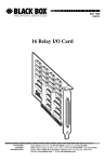
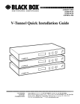
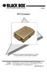
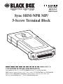
APRIL 2000
ME737A-F
ME737A-M
Sync SHM-NPR MP/
5-Screw Terminal Block
CUSTOMER SUPPORT INFORMATION
Order toll-free in the U.S.: Call 877-877-BBOX (outside U.S. call 724-746-5500)
FREE technical support 24 hours a day, 7 days a week: Call 724-746-5500 or fax 724-746-0746
Mailing address: Black Box Corporation, 1000 Park Drive, Lawrence, PA 15055-1018
Web site: www.blackbox.com • E-mail: [email protected]
SYNC SHM-NPR MP/5-SCREW TERMINAL BLOCK
FEDERAL COMMUNICATIONS COMMISSION
AND
INDUSTRY CANADA
RADIO FREQUENCY INTERFERENCE STATEMENTS
This equipment generates, uses, and can radiate radio frequency energy and if
not installed and used properly, that is, in strict accordance with the
manufacturer’s instructions, may cause interference to radio communication. It
has been tested and found to comply with the limits for a Class A computing
device in accordance with the specifications in Subpart J of Part 15 of FCC rules,
which are designed to provide reasonable protection against such interference
when the equipment is operated in a commercial environment. Operation of
this equipment in a residential area is likely to cause interference, in which case
the user at his own expense will be required to take whatever measures may be
necessary to correct the interference.
Changes or modifications not expressly approved by the party responsible for
compliance could void the user’s authority to operate the equipment.
This digital apparatus does not exceed the Class A limits for radio noise emission from
digital apparatus set out in the Radio Interference Regulation of Industry Canada.
Le présent appareil numérique n’émet pas de bruits radioélectriques dépassant les limites
applicables aux appareils numériques de classe A prescrites dans le Règlement sur le
brouillage radioélectrique publié par Industrie Canada.
1
SYNC SHM-NPR MP/5-SCREW TERMINAL BLOCK
NORMAS OFICIALES MEXICANAS (NOM)
ELECTRICAL SAFETY STATEMENT
INSTRUCCIONES DE SEGURIDAD
1. Todas las instrucciones de seguridad y operación deberán ser leídas antes
de que el aparato eléctrico sea operado.
2. Las instrucciones de seguridad y operación deberán ser guardadas para
referencia futura.
3. Todas las advertencias en el aparato eléctrico y en sus instrucciones de
operación deben ser respetadas.
4. Todas las instrucciones de operación y uso deben ser seguidas.
5. El aparato eléctrico no deberá ser usado cerca del agua—por ejemplo,
cerca de la tina de baño, lavabo, sótano mojado o cerca de una alberca,
etc..
6. El aparato eléctrico debe ser usado únicamente con carritos o pedestales
que sean recomendados por el fabricante.
7. El aparato eléctrico debe ser montado a la pared o al techo sólo como sea
recomendado por el fabricante.
8. Servicio—El usuario no debe intentar dar servicio al equipo eléctrico más
allá a lo descrito en las instrucciones de operación. Todo otro servicio
deberá ser referido a personal de servicio calificado.
9. El aparato eléctrico debe ser situado de tal manera que su posición no
interfiera su uso. La colocación del aparato eléctrico sobre una cama,
sofá, alfombra o superficie similar puede bloquea la ventilación, no se
debe colocar en libreros o gabinetes que impidan el flujo de aire por los
orificios de ventilación.
2
SYNC SHM-NPR MP/5-SCREW TERMINAL BLOCK
10. El equipo eléctrico deber ser situado fuera del alcance de fuentes de calor
como radiadores, registros de calor, estufas u otros aparatos (incluyendo
amplificadores) que producen calor.
11. El aparato eléctrico deberá ser connectado a una fuente de poder sólo del
tipo descrito en el instructivo de operación, o como se indique en el
aparato.
12. Precaución debe ser tomada de tal manera que la tierra fisica y la
polarización del equipo no sea eliminada.
13. Los cables de la fuente de poder deben ser guiados de tal manera que no
sean pisados ni pellizcados por objetos colocados sobre o contra ellos,
poniendo particular atención a los contactos y receptáculos donde salen
del aparato.
14. El equipo eléctrico debe ser limpiado únicamente de acuerdo a las
recomendaciones del fabricante.
15. En caso de existir, una antena externa deberá ser localizada lejos de las
lineas de energia.
16. El cable de corriente deberá ser desconectado del cuando el equipo no
sea usado por un largo periodo de tiempo.
17. Cuidado debe ser tomado de tal manera que objectos liquidos no sean
derramados sobre la cubierta u orificios de ventilación.
18. Servicio por personal calificado deberá ser provisto cuando:
A:
El cable de poder o el contacto ha sido dañado; u
B:
Objectos han caído o líquido ha sido derramado dentro del
aparato; o
C:
El aparato ha sido expuesto a la lluvia; o
D:
El aparato parece no operar normalmente o muestra un cambio en
su desempeño; o
E:
El aparato ha sido tirado o su cubierta ha sido dañada.
3
SYNC SHM-NPR MP/5-SCREW TERMINAL BLOCK
TRADEMARKS USED IN THIS MANUAL
Any trademarks mentioned in this manual are
acknowledged to be the property of the trademark
owners.
4
SYNC SHM-NPR MP/5-SCREW TERMINAL BLOCK
Contents
1. Specifications . . . . . . . . . . . . . . . . . . . . . . . . . . . 6
2. Introduction. . . . . . . . . . . . . . . . . . . . . . . . . . . . 8
2.1 Description. . . . . . . . . . . . . . . . . . . . . . . . . . 8
2.2 Features . . . . . . . . . . . . . . . . . . . . . . . . . . . . 9
2.3 Applications . . . . . . . . . . . . . . . . . . . . . . . . . 10
3. Installation . . . . . . . . . . . . . . . . . . . . . . . . . . . . . 11
5
SYNC SHM-NPR MP/5-SCREW TERMINAL BLOCK
1. Specifications
Maximum Distance—8.5 mi. (13.6 km)
Operation—4-wire half- or full-duplex
Protocol—Synchronous
Speed—1200, 2400, 4800, 9600, 19,200 bps
Transmit Timing—Internal or external clock
Transmission Level—6 dBm
Table 1-1. Transmission Controls
Transmission Controls
SHM-NPR Status
RTS/CTS delay (Circuits 105/106)
DSR (Circuit 107)
DCD (Circuit 109)
DCD (Circuit 109), Multipoint
20 millisecs
Constantly ON
Constantly ON
Carrier controlled
Terminal Interface—RS-232 (DCE)
Telephone Line Interface—5-screw (4-wire and ground)
connector block with cable strain relief inside plastic
cover
6
SYNC SHM-NPR MP/5-SCREW TERMINAL BLOCK
Connectors—(1) DB25 male or female, (1) 5-screw
terminal block
Temperature Tolerance—32 to 140°F (0 to 60°C)
Maximum Altitude—Up to 10,000 ft. (3048 m)
Humidity—Up to 95%, noncondensing
Power—Uses ultra-low power from the RS-232 data and
control signals (Pin 4 or 20 [6 VDC]); AC/DC
overvoltage protection circuits connected via isolation
transformers rated at 1500 VRMS
Size—0.9"H x 2.1"W x 4.3"D (2.3 x 5.3 x 10.9 cm)
Weight—3.3 oz. (93.6 g)
7
SYNC SHM-NPR MP/5-SCREW TERMINAL BLOCK
2. Introduction
2.1 Description
The Sync SHM-NPR MP/5-Screw Terminal Block uses
ultra-low power from the standard EIA RS-232-C/CCITT
V.24 data and control signals.
The SHM-NPR will operate even if only Transmit Data
(Circuit 105) is connected (without the terminal
sending Request to Send [Circuit 105] or Data Terminal
Ready [Circuit 108.2] signals). Both positive and
negative signals are generated in compliance with EIA
RS-232-C/CCITT V.24 standards regardless of constantly
high or constantly low Transmit Data (Circuit 103). An
internal or external clock provides transmit timing.
The low transmit level of -6 dBm minimizes crosstalk
onto adjacent circuits within the same cable. The SHMNPR uses differential diphase modulation to provide
immunity to background noise, eliminate line
distortion, and permit efficient transmission and
reception of serial data. Data is transmitted and received
at a balanced impedance, ensuring excellent immunity
to circuit noise. Additionally, the SHM-NPR is coupled
to the telephone line through isolation transformers
8
SYNC SHM-NPR MP/5-SCREW TERMINAL BLOCK
which, in conjunction with electronic circuitry, protect
against AC or DC overvoltages. The transformers are
rated at over 1,500 V RMS, so the SHM-NPR is suitable
for connection to local circuits provided by most
national telephone administrations (PTTs).
2.2 Features
• Compact and lightweight.
• Easy to install.
• Synchronous transmission from 1.2 to 19.2 kbps.
• Simple strap settings.
• No AC power required.
• Transformer isolated.
• Enclosed line termination unit.
• Strain relief for line cable.
• Internal or external clocking.
• Full- or half-duplex, point-to-point or multipoint.
9
SYNC SHM-NPR MP/5-SCREW TERMINAL BLOCK
• Plugs directly into RS-232C/V.24 terminal
connector.
• Transmission range up to 11 miles (17.7 km).
2.3 Applications
The Sync SHM-NPR is used for local data distribution,
connecting full-duplex synchronous terminals to
computers. Stretching beyond the usual limit of 50 ft.
(15.2 m), a pair of Sync SHM-NPRs will ensure integrity
of data transmission using unconditioned 4-wire
telephone lines for distances up to 11 miles (17.7 km),
depending on gauge and data rates (see Table 1-1).
Since they’re compact and require no AC power, the
SHM-NPRs are ideal for economical data distribution
within large industrial sites, office complexes, and
campus environments.
4-Wire
Telephone Line
SYNC
TERMINAL
SYNC
COMPUTER
Sync Computer
Sync Terminal
Sync SHM-NPR MP
Figure 2-1. Typical Application.
10
SYNC SHM-NPR MP/5-SCREW TERMINAL BLOCK
3. Installation
Follow the steps listed below to install the Sync
SHM-NPR MP.
1. Open the modem cover by removing the four
screws that fasten the two halves of the cover
together
2. Connect the four-wire telephone line to the screw
terminal block, transmit pair to XMT and receive
pair to RCV. A ground is provided where needed
to connect the cable shield.
3. Review Table 3-1 since the modem may already be
factory-strapped to suit your application.
4. Strap the modem according to Table 3-1 for data
rate, internal or external clock, and carrier “on” or
“controlled.” Refer to Figure 3-1 for strap location.
11
SYNC SHM-NPR MP/5-SCREW TERMINAL BLOCK
Table 3-1. Strap Selection
Strap Identity
Function
Possible Positions
Normal Factory
Setting
Rate
Selects data
transmit rate
1200 bps
2400 bps
4800 bps
9600 bps
19200 bps
Clock
Selects timing
source
External
Internal
Carrier
Selects
point-to-point
(ON) or multipoint
(CONTROL)
ON
Control
9,600 bps
External
Control
5. Close the unit and fasten the four screws.
6. Connect the modem directly to the 25-pin
connector of the terminal or computer port, and
fasten with the two screws (one on each side of the
modem connector).
12
SYNC SHM-NPR MP/5-SCREW TERMINAL BLOCK
XMT G RCV
RATE
CK
INT •
C•
EXT •
CD
• ON
• C
• CONT
19.2
9.6
4.8
2.4
1.2
••
••
••
••
••
Figure 3-1. Location of Straps.
13
© Copyright 2000. Black Box Corporation. All rights reserved.
1000 Park Drive • Lawrence, PA 15055-1018 • 724-746-5500 • Fax 724-746-0746